EP1573261B9 - Method for producing elements from phase change material - Google Patents
Method for producing elements from phase change material Download PDFInfo
- Publication number
- EP1573261B9 EP1573261B9 EP03795952A EP03795952A EP1573261B9 EP 1573261 B9 EP1573261 B9 EP 1573261B9 EP 03795952 A EP03795952 A EP 03795952A EP 03795952 A EP03795952 A EP 03795952A EP 1573261 B9 EP1573261 B9 EP 1573261B9
- Authority
- EP
- European Patent Office
- Prior art keywords
- pcm
- tube
- tube sections
- filled
- process according
- Prior art date
- Legal status (The legal status is an assumption and is not a legal conclusion. Google has not performed a legal analysis and makes no representation as to the accuracy of the status listed.)
- Expired - Lifetime
Links
- 238000004519 manufacturing process Methods 0.000 title claims abstract description 16
- 239000012782 phase change material Substances 0.000 title abstract 2
- 239000000463 material Substances 0.000 claims abstract description 20
- 238000000034 method Methods 0.000 claims description 23
- 239000004033 plastic Substances 0.000 claims description 23
- 229920003023 plastic Polymers 0.000 claims description 23
- 239000007788 liquid Substances 0.000 claims description 18
- 230000008569 process Effects 0.000 claims description 17
- 238000010276 construction Methods 0.000 claims description 14
- 239000008187 granular material Substances 0.000 claims description 13
- 238000003825 pressing Methods 0.000 claims description 7
- 150000003839 salts Chemical class 0.000 claims description 7
- LQERIDTXQFOHKA-UHFFFAOYSA-N nonadecane Chemical compound CCCCCCCCCCCCCCCCCCC LQERIDTXQFOHKA-UHFFFAOYSA-N 0.000 claims description 6
- 238000007789 sealing Methods 0.000 claims description 6
- 239000012188 paraffin wax Substances 0.000 claims description 5
- 239000011265 semifinished product Substances 0.000 claims description 5
- 238000001816 cooling Methods 0.000 claims description 4
- QHFQAJHNDKBRBO-UHFFFAOYSA-L calcium chloride hexahydrate Chemical compound O.O.O.O.O.O.[Cl-].[Cl-].[Ca+2] QHFQAJHNDKBRBO-UHFFFAOYSA-L 0.000 claims description 3
- IEMMJPTUSSWOND-UHFFFAOYSA-N lithium;nitrate;trihydrate Chemical compound [Li+].O.O.O.[O-][N+]([O-])=O IEMMJPTUSSWOND-UHFFFAOYSA-N 0.000 claims description 3
- 239000000203 mixture Substances 0.000 claims description 3
- 239000004745 nonwoven fabric Substances 0.000 claims 10
- 239000011888 foil Substances 0.000 claims 3
- CBFCDTFDPHXCNY-UHFFFAOYSA-N icosane Chemical compound CCCCCCCCCCCCCCCCCCCC CBFCDTFDPHXCNY-UHFFFAOYSA-N 0.000 claims 2
- 230000001427 coherent effect Effects 0.000 claims 1
- 238000005338 heat storage Methods 0.000 abstract description 8
- 239000010410 layer Substances 0.000 description 15
- 239000004952 Polyamide Substances 0.000 description 8
- 239000011324 bead Substances 0.000 description 8
- 238000009413 insulation Methods 0.000 description 8
- 239000012071 phase Substances 0.000 description 8
- 229920002647 polyamide Polymers 0.000 description 8
- 229910052751 metal Inorganic materials 0.000 description 7
- 239000002184 metal Substances 0.000 description 7
- 239000007787 solid Substances 0.000 description 7
- 230000007704 transition Effects 0.000 description 7
- 238000003466 welding Methods 0.000 description 7
- 239000004743 Polypropylene Substances 0.000 description 4
- -1 polyethylene Polymers 0.000 description 4
- 229920001155 polypropylene Polymers 0.000 description 4
- 238000004804 winding Methods 0.000 description 4
- 230000006978 adaptation Effects 0.000 description 3
- 230000004888 barrier function Effects 0.000 description 3
- 238000010924 continuous production Methods 0.000 description 3
- 239000002826 coolant Substances 0.000 description 3
- 238000005520 cutting process Methods 0.000 description 3
- 238000010438 heat treatment Methods 0.000 description 3
- 238000007373 indentation Methods 0.000 description 3
- 238000012545 processing Methods 0.000 description 3
- 230000009467 reduction Effects 0.000 description 3
- 239000004698 Polyethylene Substances 0.000 description 2
- 229910000831 Steel Inorganic materials 0.000 description 2
- 238000010521 absorption reaction Methods 0.000 description 2
- 230000008901 benefit Effects 0.000 description 2
- 230000015572 biosynthetic process Effects 0.000 description 2
- 239000000969 carrier Substances 0.000 description 2
- 238000013461 design Methods 0.000 description 2
- 230000000694 effects Effects 0.000 description 2
- 229920001903 high density polyethylene Polymers 0.000 description 2
- 239000004700 high-density polyethylene Substances 0.000 description 2
- 238000009434 installation Methods 0.000 description 2
- 239000011810 insulating material Substances 0.000 description 2
- 230000010354 integration Effects 0.000 description 2
- 239000000155 melt Substances 0.000 description 2
- RZJRJXONCZWCBN-UHFFFAOYSA-N octadecane Chemical compound CCCCCCCCCCCCCCCCCC RZJRJXONCZWCBN-UHFFFAOYSA-N 0.000 description 2
- 239000002245 particle Substances 0.000 description 2
- 229920000573 polyethylene Polymers 0.000 description 2
- 239000000047 product Substances 0.000 description 2
- 238000005507 spraying Methods 0.000 description 2
- 239000010959 steel Substances 0.000 description 2
- 238000003860 storage Methods 0.000 description 2
- 241000264877 Hippospongia communis Species 0.000 description 1
- 230000009471 action Effects 0.000 description 1
- 239000000853 adhesive Substances 0.000 description 1
- 238000004026 adhesive bonding Methods 0.000 description 1
- 239000012876 carrier material Substances 0.000 description 1
- 238000005253 cladding Methods 0.000 description 1
- 230000003111 delayed effect Effects 0.000 description 1
- 238000011161 development Methods 0.000 description 1
- 230000018109 developmental process Effects 0.000 description 1
- 238000005265 energy consumption Methods 0.000 description 1
- 239000004744 fabric Substances 0.000 description 1
- 239000000945 filler Substances 0.000 description 1
- 229920002457 flexible plastic Polymers 0.000 description 1
- 230000001771 impaired effect Effects 0.000 description 1
- 238000003780 insertion Methods 0.000 description 1
- 230000037431 insertion Effects 0.000 description 1
- 239000007791 liquid phase Substances 0.000 description 1
- 239000012528 membrane Substances 0.000 description 1
- 235000011837 pasties Nutrition 0.000 description 1
- 239000008188 pellet Substances 0.000 description 1
- 230000000149 penetrating effect Effects 0.000 description 1
- 230000035515 penetration Effects 0.000 description 1
- 239000002985 plastic film Substances 0.000 description 1
- 229920006255 plastic film Polymers 0.000 description 1
- 239000000843 powder Substances 0.000 description 1
- 239000011241 protective layer Substances 0.000 description 1
- 239000000126 substance Substances 0.000 description 1
- 239000000758 substrate Substances 0.000 description 1
- 230000009466 transformation Effects 0.000 description 1
- 238000009827 uniform distribution Methods 0.000 description 1
- 239000001993 wax Substances 0.000 description 1
Images

Classifications
-
- C—CHEMISTRY; METALLURGY
- C09—DYES; PAINTS; POLISHES; NATURAL RESINS; ADHESIVES; COMPOSITIONS NOT OTHERWISE PROVIDED FOR; APPLICATIONS OF MATERIALS NOT OTHERWISE PROVIDED FOR
- C09K—MATERIALS FOR MISCELLANEOUS APPLICATIONS, NOT PROVIDED FOR ELSEWHERE
- C09K5/00—Heat-transfer, heat-exchange or heat-storage materials, e.g. refrigerants; Materials for the production of heat or cold by chemical reactions other than by combustion
- C09K5/02—Materials undergoing a change of physical state when used
- C09K5/06—Materials undergoing a change of physical state when used the change of state being from liquid to solid or vice versa
- C09K5/063—Materials absorbing or liberating heat during crystallisation; Heat storage materials
-
- F—MECHANICAL ENGINEERING; LIGHTING; HEATING; WEAPONS; BLASTING
- F28—HEAT EXCHANGE IN GENERAL
- F28D—HEAT-EXCHANGE APPARATUS, NOT PROVIDED FOR IN ANOTHER SUBCLASS, IN WHICH THE HEAT-EXCHANGE MEDIA DO NOT COME INTO DIRECT CONTACT
- F28D20/00—Heat storage plants or apparatus in general; Regenerative heat-exchange apparatus not covered by groups F28D17/00 or F28D19/00
- F28D20/02—Heat storage plants or apparatus in general; Regenerative heat-exchange apparatus not covered by groups F28D17/00 or F28D19/00 using latent heat
-
- Y—GENERAL TAGGING OF NEW TECHNOLOGICAL DEVELOPMENTS; GENERAL TAGGING OF CROSS-SECTIONAL TECHNOLOGIES SPANNING OVER SEVERAL SECTIONS OF THE IPC; TECHNICAL SUBJECTS COVERED BY FORMER USPC CROSS-REFERENCE ART COLLECTIONS [XRACs] AND DIGESTS
- Y02—TECHNOLOGIES OR APPLICATIONS FOR MITIGATION OR ADAPTATION AGAINST CLIMATE CHANGE
- Y02E—REDUCTION OF GREENHOUSE GAS [GHG] EMISSIONS, RELATED TO ENERGY GENERATION, TRANSMISSION OR DISTRIBUTION
- Y02E60/00—Enabling technologies; Technologies with a potential or indirect contribution to GHG emissions mitigation
- Y02E60/14—Thermal energy storage
-
- Y—GENERAL TAGGING OF NEW TECHNOLOGICAL DEVELOPMENTS; GENERAL TAGGING OF CROSS-SECTIONAL TECHNOLOGIES SPANNING OVER SEVERAL SECTIONS OF THE IPC; TECHNICAL SUBJECTS COVERED BY FORMER USPC CROSS-REFERENCE ART COLLECTIONS [XRACs] AND DIGESTS
- Y10—TECHNICAL SUBJECTS COVERED BY FORMER USPC
- Y10T—TECHNICAL SUBJECTS COVERED BY FORMER US CLASSIFICATION
- Y10T428/00—Stock material or miscellaneous articles
- Y10T428/13—Hollow or container type article [e.g., tube, vase, etc.]
- Y10T428/1334—Nonself-supporting tubular film or bag [e.g., pouch, envelope, packet, etc.]
Definitions
- the invention relates to a method for producing elements from or with latent heat-storing material - hereinafter referred to by the abbreviation "PCM" - which are provided with a hose , and also elements made of or with PCM.
- PCM latent heat-storing material
- element PCM in any form, type, consistency, color, particle size, namely body such as plates, profiles, tubes, blocks, balls, grains, pillows, powders, etc.
- PCM materials are used for the regulation of the temperature conditions in the rooms.
- PCM materials are bonded or bonded to substrates by various processes, for example by impregnating webs in PCM baths or by spraying liquid PCM onto insulating materials or by introducing coated PCM pellets into components with a foam-like structure.
- the PCM carriers are basically introduced only as an intermediate layer between two insulating layers for thermal insulation of rooms.
- Out US 4,259,401 are PCM element known, whereby the PCM material can be given in hoses given.
- the object of this prior art is to provide a method which can be used to produce as economically as possible elements made of or with PCM, which are suitable for a wide range of applications and permit simple processing.
- PCM can be supplied in liquid form or as granules or as a strand piecewise or endlessly.
- the PCM-filled hose can be flexible or dimensionally stable.
- the hose expediently consists of diffusion-tight plastic, so that no PCM can escape from the casing and conversely no particles can penetrate from the outside into the interior of the hose.
- paraffin-based PCM comes as plastic z.
- polyamide (PA) in particular for producing a flexible hose into consideration.
- polyethylene (HDPE) or polypropylene (PP) or polyamide (PA) may be used as the plastic material for a flexible hose.
- the cross-sectional shape of the hose corresponds to the intended use. The same applies to the cross-sectional size, which may include a few square millimeters or - depending on the desired storage capacity per unit length - considerably larger areas.
- the tube is extruded in the manufacturing line and PCM is introduced into the freshly extruded tube.
- the hose after leaving the extruder die and before entering a cooling zone with PCM - preferably in liquid form - are filled.
- PCM as a strand in a solid state with a predetermined cross-section, for example. With a flat-oval cross-section, and to lead the strand for producing a wrapper by a bath or produce the wrapper by spraying liquid plastic.
- the filling of liquid PCM in a hose which exits continuously from an extruder die and already has sufficient for filling liquid PCM dimensional stability.
- PCM is preferably supplied centrally through the extruder nozzle into the forming tube, advantageously with a vertical working direction.
- the tube after filling with PCM namely with PCM granules or preferably with PCM in the liquid state, divided into tube sections of suitable length or stored on a support such as a coil for further processing elsewhere.
- the length of the tube sections also depends on their intended use and may be a few millimeters or even several meters.
- the selected PCM material is securely wrapped, and the PCM-filled tube sections can be fed to further processing.
- the PCM-filled plastic hose can be constricted at predetermined locations to form the hose sections, and the constrictions can be welded.
- This process step leads to strings consisting of tube sections, which, as will be described, can be further processed for the production of insulating and / or heat storage elements.
- the PCM-filled tube sections at the bottlenecks can also be separated from each other, wherein expediently the constrictions are severed, in such a way that the ends of the tube sections remain welded.
- the PCM-filled hose can be guided through a press and the constrictions and welds can be brought about by means of tempered pressing tools.
- the tube can be constricted cyclically with reciprocating pressing tools at the predetermined locations and welded.
- the tube can be transported through for necking and welding between two opposite caterpillars occupied with pressure and welding tools.
- the hose is transported between two wheels which are filled with pressure and welding tools on the circumference.
- it is particularly suitable for continuous production and economical process for the production of hose sections of almost any size, as regards the hose lengths and their cross-sectional size and also cross-sectional shape.
- granules of PCM-filled cushions can be produced from tube sections cut from the strand. With the granules predetermined cavities in walls of buildings to form latent heat storage can be filled as well as containers or chambers in construction or insulating.
- individual or strand-related, PCM-filled tube sections can also be on a support z.
- the tube sections can be arranged parallel to each other on the web or on the film.
- Flexible carriers with PCM-filled tube sections can be easily stored, transported, handled and cut to the appropriate length, especially as products for construction purposes by winding. For other requirements form-stable films are preferable as a carrier of the tube sections.
- Such a semi-finished product can be economically, for example.
- Manufacture so that an endless web and an endless strand of PCM-filled tube sections in the nip of a pair of rollers and joined together and coated on the side facing away from the fleece with the film from an extruder die become.
- the production of the endless strand of PCM-filled tube sections immediately precedes the production of such an endless web with PCM-filled tube sections, so that the production of this multilayer web material can take place in a manufacturing plant.
- the film may be drawn across the tube sections to the web and secured to the web between adjacent tube sections.
- each tube section receives a protective layer through the film at the locations not covered by the nonwoven, with which each tube section is simultaneously secured in the desired position on the nonwoven web.
- an endless fleece and individually supplied from a magazine tube sections can be merged in the nip of a pair of rollers and the tube sections are there coated with the film from an extruder die and fixed by gluing the film to the web between the tube sections.
- Industrial buildings such as production halls and warehouses, etc. are today built to a considerable extent as lightweight constructions. They consist of steel structures, which are then insulated and clad in the wall and roof area as needed.
- the roof of lightweight constructions usually consists of plastic-coated trapezoidal sheet metal profiles, which rest on the supporting steel structure and are bolted to it.
- the profiled sheets are connected to each other with rivets.
- the trapezoidal sheets are rigid and walkable after installation.
- Above the trapezoidal sheets are as a further roof structure usually a vapor barrier, e.g. from a self-adhesive thick film, a thermal insulation with a layer thickness of about 160 mm and finally a flat roof seal made of two layers of bituminous membrane or a layer of a suitable plastic geomembrane provided.
- bead fillers made of insulating material, which are cut to the shape of the deep bead, can be inserted.
- the sheet can be perforated in the deep groove, and in the deep bead itself an insulation strips can be inserted.
- the invention makes it possible to use the available space in lightweight constructions by the deep corrugations of the layer or the trapezoidal sheet metal space for receiving a storage mass for the absorption of heat energy.
- massive components with considerable weight which are also considered as heat storage
- the load capacity of the lightweight construction would be overwhelming, elements can be specifically selected with PCM and bring in a simple way in the low corrugations of the profile layer.
- these heat storage would cause a reduction in the temperature below the metal roof, while they give off heat at cool night temperatures, so that they bring about a balanced overall climate in the interior.
- PCM may be comprised of a plurality of encapsulated members, and is preferably disposed in cavities such as chambers, honeycombs, or the like. Depending on the material type, the PCM elements can also be incorporated as granules into cavities as well as into the deep corrugations of trapezoidal sheet metal profiles. However, the elements may also consist of strands that are easily cut to length.
- the effect of the PCM as a balancing element between high and low ambient temperatures is particularly sustainable when the phase transition temperature of the PCM is in the range of 15-40 ° C, especially in the range of 20-35 ° C.
- the temperatures occurring at the place of use of the layer are to be taken into account so that the phase transformation heat of the PCM can be used to equalize the different temperatures.
- the PCM is in the solid or solid state.
- phase transition temperature of this material is 25 ° C
- the transition of the PCM from the solid to the liquid phase occurs when higher ambient temperatures in the range eg 25-30 ° C occur, with the result that the heating of the layer and thus the interior is delayed accordingly.
- the more PCM is used and the higher the heat storage capacity of the material the longer the interior retains a pleasant climate.
- the interior cools considerably more slowly in the evening or at night and achieves a correspondingly lower reduction of the internal temperature, if the elements of PCM under the action of falling below the phase transition temperature of 20 ° C temperatures release phase transition heat for a long time until they eventually go over completely depending on the duration of the rigid phase. As they release phase transition heat, they prevent an abrupt drop in temperatures around the layer and hence in the interior.
- the PCM is sealed in the elements in the cavities, in particular in the indentations or chambers, from the environment by a barrier, in particular enclosed by a sealing, above all, diffusion-tight enclosure.
- the wrapper serves both to protect the PCM, the z. B. otherwise evaporate or may be impaired in its function by penetrating into the envelope other substances, as well as to prevent an immediate penetration of PCM in the lows and from there possibly in the environment.
- the wrapper is flexible and allows changes in shape of the PCM elements in the powdery, granular, liquid or pasty state.
- a flexible enclosure of the elements e.g. As a plastic hose has a number of advantages such as usually low weight, easy transport, easy installation i.
- a PCM is chosen and provided with a suitable cladding, it can be introduced into the crimp in both the molten and the solid state. If lower outside temperatures cause the solid state of the PCM of the elements when introducing the elements into the depression, the PCM melts with a corresponding adaptation to the shape of the deep bead, as soon as the outside temperatures rise and the PCM melts.
- an adaptation to the shape of the craters is achieved with time shift even with elements of PCM in the solid state when introducing the elements, if the envelope is correspondingly flexible.
- An adaptation to the shape of the deep bead is understood essentially to mean that e.g. a roughly circular in cross-section element with wrapping after insertion into the deep bead takes a flattened shape at the bottom of the deep bead.
- the tubular sheath is in the case of longitudinal cavities as deep corrugations be divided into each individually sealed tube sections, which can be arranged individually and / or in a row interconnected in the cavities.
- a sectionally divided tubular casing with PCM in this manner has the advantage that, when leaks occur due to damage, only individual tube elements and not the entire tube length are affected or leaking.
- each required hose length can be easily prepared by cutting off the connection between two hose elements.
- the wrapping of the PCM from a tear-resistant, liquid and diffusion-tight plastic film can be multilayered.
- z. B. a layer, namely z. B. a fabric or a nonwoven assigned the function of mechanical strength, while other layers z. B. take over the sealing functions.
- the PCM should have the highest possible phase transition heat, so that the temperature-compensating effect of the PCM leads to a largely balanced climate in the interior of buildings of the type concerned here.
- the PCM may be made of a wax, e.g. from a paraffin mixture such as EICOSAN, NONADECAN or OKTADEKAN.
- the PCM from a salt, salt hydrate z. B. from calcium chloride hexahydrate or lithium nitrate trihydrate.
- elements according to the invention can not be used only for flat roofs but, with appropriate design of the elements, also for pitched roofs or for walls. So that the elements do not shift under the weight of the PCM, z. B. in the case of walls or pitched roofs or the like structural inserts with transverse webs on the bottom of the cavities or deep corrugations, the slipping or
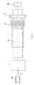
- a station 1 for producing the strand 5 comprises a station 1 for producing the strand 5, a station 2 for the withdrawal of the strand 5 and a station 3 for cutting the same or a station 4 for winding the Stranges 5.
- an extruder 7 is supplied with liquid PCM from a container 8 via a line 9, as shown, centrally.
- the transport and working direction in the extruder 7 is preferably, as shown, vertically.
- heated plastic is fed via a line 11a to an extruder head 11 for the continuous production of an endless tube 12.
- the liquid PCM is introduced into the tube 12 immediately after formation of the tube 12 so as to form the PCM filled strand below the outlet of the extruder die 11.
- the supplied via the line 9 liquid PCM is fed via a centrally guided by the extruder head 11 metering tube or supply pipe 9c, is entered from the downwardly projecting end PCM in the just-formed and still warm tube 12. So that the PCM retains the feed temperature during the passage through the extruder head 11 or, in any case, is heated within permissible limits (depending on the PCM material), a coolant circuit is arranged on and in the extruder head 11.
- This consists in the present example of a line 9a for supplying the coolant to a coaxially extending through the extruder head 11 cooling jacket 9b, from which the coolant is discharged via a line 9d again.
- the arrows show the supply of the plastic to the extruder head 11 and the outlet of the tube 12 from the nozzle opening as well as the exit of the liquid PCM from the lower end of the feed tube 9c.
- the strand 5 passes through a temperature-controlled pressing device 13 (FIG. Fig. 3 ) or 13a ( Fig. 4 ), in the Fig. 1 are indicated by X and Z respectively.
- the still warm strand 5 is here clockwise constricted and welded to the constrictions 14 so that the strand 5 now consists of over the welded constrictions 14 interconnected hose sections 6.
- Fig. 3 (Detail X) are the constrictions 14 by perpendicular to the feed direction 15 of the strand 5 cyclically reciprocating, tempered pressing tools 16, 17 formed.
- the tube sections 6 are sealingly welded at both ends.
- the continuously produced endless strand 5 of PCM-filled tube sections 6 is guided via deflecting rollers 22, 23 through a cooling device 24 and from the station 1 via the station 2 provided with transport devices 25, 26 either to the station 3 or to the station 4.
- station 3 depending on the desired product, a division of the strand 5 into individual tube sections 6 is made by severing the constrictions 14 between the tube sections 6.
- the strand 5 is divided into strand sections, which consist of a plurality of further contiguous hose sections 6.
- the strand 5 can also be supplied instead of the station 3 of the station 4 for winding on a spool core 27 in a winding device 28.
- the strand wraps thus formed are further processed elsewhere.
- PCM-filled hose sections are produced in the form of granules.
- the strand 5 is also divided by making and welding constrictions in hose sections, which are sealingly closed at both ends. If, as in the present case, granules of PCM-filled tube sections to be produced, a correspondingly short length in the range of 3 to 7 mm for the tube sections in the station 5 'is selected, and also the cross-sectional dimensions of the strand 5 are minimized. They are in the range of 3 to 7 mm.
- the PCM-filled Hose sections existing strand 5 then passes through the cutting station 3, where the tube sections are separated from each other with a correspondingly short length and then collected as granules in a container 32.
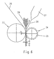
- Fig. 6 are two rollers, namely a feed roller 33 and a negative roller 34 with uniformly circumferentially arranged recesses 35, arranged in the manner shown in the drawing, namely with height offset H.
- An endless web 36 runs continuously as a carrier material to the nip and is here combined with a discharged from an extruder die 37 film 38 for incorporating supplied from a magazine 39 PCM-filled tube sections 6 in tube form.
- the PCM-filled tube sections 6 are held and guided during the merging into the receiving openings 35 of the negative roller 34.
- the tube sections 6 are coated with the film 38 from the extruder die 37, and the film 38 is bonded to the nonwoven 36 between the tube sections 6.
- the tube sections 6 always receive a predetermined position on the web 36 and each other, and the film 38 protects and fixes the PCM-filled tube sections 6.
- the produced sheet or strip-shaped semi-finished product can be wound up to save space and transport and easy to handle and cut to the desired length.
- the length of the tube sections 6 is selectable and depends on the setting of the manufacturing plant, as for example. In Fig. 1 is shown. Larger web widths can be achieved both by appropriately sized hose sections 6 as well as by using a suitably sized roll width, z. B.
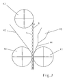
- Fig. 7 be in the gap of two in the from the Drawing evidently arranged groove rollers 40, 41 an endless web 42 and a feed roller 43, which may also be an unwinding, one or more strands 5 of PCM-filled tube sections 6, formed z.
- a facility such as in Fig. 4 represented led into the nip and on the side facing away from the web 42 with a film 44 from an extruder die 45, as shown in the drawing, coated.
- an endless web with integration of PCM-filled tube sections 6 is produced.
- by a corresponding dimensioning of the width of the rolls and the number of parallel juxtaposed Abwickelwalzen for the strands 5, etc. different widths produced, in which a corresponding number of strands or strings 5 PCM-filled tube sections 6 to arrange side by side is.
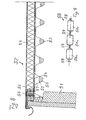
- the in Fig. 8 shown in cross section building part of a lightweight construction has a wall portion 51 on which a flat roof 52 rests with low inclination.
- the flat roof 52 has on its underside a trapezoidal profile 53 made of sheet metal and above this a thermal insulation 55 with a vapor barrier 54 between the trapezoidal profile 53 and the thermal insulation 55 and the upper end a roof sealing sheet 56.
- elements 58 are inserted PCM, which have an approximately circular cross-section and a tubular sheath 59 of a tear-resistant, liquid and diffusion-tight film in this embodiment.
- the elements 58 are preferably subdivided into individual sections 58a which are sealed against each other and interconnected by constrictions 59 of the tubular wrapping material, but which can be easily severed to easily cut the elements 58 to length.
- the elements 58 are conveniently placed in place in the dimples 57 when the trapezoidal profiles 53 are mounted.
- the elements 58 can also be made as rigid rods or tubes made of PCM with a corresponding sheath, which are inserted as a whole into the deep corrugations 57 or comparable cavities.
- the element 58 has a flexible envelope 59, the shape changes of the Elements 58 from PCM adapts.
- the element 58 may also consist of granules.
- the portions 58 a are separated from each other and filled in the valley beads 57.
- the space available in the indentations 57 of the trapezoidal profile 53 for receiving PCM in the form of elements 58 or 58a is used to absorb heat energy.
- the PCM elements 58 and 58a cause, as already described in the beginning of the description, on hot days in summer as a heat storage, a reduction of the temperature in this layer or below the roof, while at cool night temperatures release heat, so that a Balanced climate in the interior of the building is brought about.
- Fig. 7 insert visible hose sections 6. If, as in the present example, deep grooves 57 are not suitable for receiving PCM elements, it is also possible to use webs with tube sections 6 as shown in FIG Fig. 6 emerge, be used.
- plastic for the production of the tube 12 or of the strand 5 or of the tube sections 6 (FIG. Fig. 1-7 ) and also for the PCM elements (58 or 58a ( 8 and 9 )) can z.
- PCM polyamide (PA) paraffin based PCM polyamide
- PP polypropylene
- PA polyamide
Landscapes
- Engineering & Computer Science (AREA)
- Chemical & Material Sciences (AREA)
- Thermal Sciences (AREA)
- Physics & Mathematics (AREA)
- Chemical Kinetics & Catalysis (AREA)
- General Engineering & Computer Science (AREA)
- Mechanical Engineering (AREA)
- Combustion & Propulsion (AREA)
- Materials Engineering (AREA)
- Organic Chemistry (AREA)
- Building Environments (AREA)
- Extrusion Moulding Of Plastics Or The Like (AREA)
- Central Heating Systems (AREA)
- Heat-Pump Type And Storage Water Heaters (AREA)
- Crystals, And After-Treatments Of Crystals (AREA)
Abstract
Description
Die Erfindung betrifft ein Verfahren zum Herstellen von Elementen aus oder mit latentwärmespeicherndem Material - nachfolgend mit der Abkürzung "PCM" bezeichnet -, die mit einem Schlauch versehen werden, und ebenso Elemente aus oder mit PCM.The invention relates to a method for producing elements from or with latent heat-storing material - hereinafter referred to by the abbreviation "PCM" - which are provided with a hose , and also elements made of or with PCM.
Dabei umfaßt der Begriff "Element" PCM in jeder Form, Art, Konsistenz, Farbe, Teilchengröße, nämlich Körper wie Platten, Profile, Rohre, Blöcke, Kugeln, Körner, Kissen, Pulver etc.The term "element" PCM in any form, type, consistency, color, particle size, namely body such as plates, profiles, tubes, blocks, balls, grains, pillows, powders, etc.
Aus der
Diesem Stand der Technik gegenüber besteht die Aufgabe, ein Verfahren vorzusehen, mit dem sich möglichst wirtschaftlich Elemente aus oder mit PCM herstellen lassen, die sich für einen breiten Anwendungsbereich eignen und eine einfache Verarbeitung gestatten.The object of this prior art is to provide a method which can be used to produce as economically as possible elements made of or with PCM, which are suitable for a wide range of applications and permit simple processing.
Ausgehend von einem Verfahren der eingangs genannten Art wird diese Aufgabe erfindungsgemäß dadurch gelöst, daß
- der Schlauch aus einem Kunststoffmaterial extrudiert wird,
- PCM kontinuierlich oder taktweise zugeführt wird,
- PCM in den frisch extrudierten Schlauch eingefüllt bzw. eingeführt wird
- der PCM-gefüllte Schlauch in Schlauchabschnitte unterteilt oder gespeichert z. B. aufgespult wird.
- the tube is extruded from a plastic material,
- PCM is fed continuously or intermittently,
- PCM is filled or introduced into the freshly extruded tube
- the PCM-filled tube is divided into tube sections or stored z. B. is wound up.
Dabei kann PCM flüssig oder als Granulat oder als Strang stückweise oder endlos zugeführt werden. Je nach Verwendungszweck kann der PCM-gefüllte Schlauch flexibel oder formstabil sein.In this case, PCM can be supplied in liquid form or as granules or as a strand piecewise or endlessly. Depending on the intended use, the PCM-filled hose can be flexible or dimensionally stable.
Der Schlauch besteht zweckmäßig aus diffusionsdichtem Kunststoff, damit aus der Umhüllung kein PCM entweichen und umgekehrt keine Partikel von außen in das Innere des Schlauches eindringen können. Bei PCM auf Paraffinbasis kommt als Kunststoff z. B. Polyamid (PA) insbesondere zum Herstellen eines flexiblen Schlauches in Betracht. Für den Fall der Verwendung von PCM auf Salzbasis kann als Kunststoffmaterial für einen flexiblen Schlauch Polyethylen (HDPE) oder Polypropylen (PP) oder auch hierfür Polyamid (PA) verwendet werden. Die Querschnittsform des Schlauches entspricht dem Verwendungszweck. Das gleiche gilt für die Querschnittsgröße, die wenige Quadratmillimeter oder aber - je nach gewünschter Speicherkapazität pro Längeneinheit - erheblich größere Flächen umfassen kann.The hose expediently consists of diffusion-tight plastic, so that no PCM can escape from the casing and conversely no particles can penetrate from the outside into the interior of the hose. When paraffin-based PCM comes as plastic z. As polyamide (PA) in particular for producing a flexible hose into consideration. In the case of using salt-based PCM, as the plastic material for a flexible hose, polyethylene (HDPE) or polypropylene (PP) or polyamide (PA) may be used. The cross-sectional shape of the hose corresponds to the intended use. The same applies to the cross-sectional size, which may include a few square millimeters or - depending on the desired storage capacity per unit length - considerably larger areas.
Zur Herstellung von PCM-Elementen in größerem Maßstab wird der Schlauch in der Herstellungsanlage extrudiert und PCM in den frisch extrudierten Schlauch eingefüllt bzw. einführt wird. Bevorzugt soll der Schlauch nach Verlassen der Extruderdüse und vor dem Eintritt in eine Kühlzone mit PCM - vorzugsweise in flüssiger Form - gefüllt werden. Es ist auch möglich, PCM als Strang in festem Zustand mit vorgegebenem Querschnitt, bspw. mit einem flachovalen Querschnitt, zuzuführen, und den Strang zum Herstellen einer Umhüllung durch ein Bad zu führen oder die Umhüllung durch Aufsprühen von flüssigem Kunststoffherzustellen. Bevorzugt wird jedoch, wie vorstehend angegeben, das Einfüllen von flüssigem PCM in einen Schlauch, der kontinuierlich aus einer Extruderdüse austritt und bereits eine zum Einfüllen von flüssigem PCM ausreichende Formstabilität besitzt. PCM wird dabei vorzugsweise zentral durch die Extruderdüse in den sich bildenden Schlauch hinein zugeführt, zweckmäßig mit vertikaler Arbeitsrichtung.To produce PCM elements on a larger scale, the tube is extruded in the manufacturing line and PCM is introduced into the freshly extruded tube. Preferably, the hose after leaving the extruder die and before entering a cooling zone with PCM - preferably in liquid form - are filled. It is also possible to feed PCM as a strand in a solid state with a predetermined cross-section, for example. With a flat-oval cross-section, and to lead the strand for producing a wrapper by a bath or produce the wrapper by spraying liquid plastic. However, it is preferred, as stated above, the filling of liquid PCM in a hose which exits continuously from an extruder die and already has sufficient for filling liquid PCM dimensional stability. PCM is preferably supplied centrally through the extruder nozzle into the forming tube, advantageously with a vertical working direction.
Je nach Verwendungszweck wird der Schlauch nach dem Befüllen mit PCM, nämlich mit PCM-Granulat oder bevorzugt mit PCM in flüssigem Zustand, in Schlauchabschnitte geeigneter Länge unterteilt oder auf einem Träger wie einer Spule gespeichert zwecks Weiterverarbeitung an anderer Stelle. Die Länge der Schlauchabschnitte hängt ebenfalls von ihrem Verwendungszweck ab und kann wenige Millimeter oder auch mehrere Meter betragen. In jedem Fall ist der gewählte PCM-Werkstoff sicher umhüllt, und die PCM-gefüllten Schlauchabschnitte können der Weiterverarbeitung zugeführt werden.Depending on the intended use, the tube after filling with PCM, namely with PCM granules or preferably with PCM in the liquid state, divided into tube sections of suitable length or stored on a support such as a coil for further processing elsewhere. The length of the tube sections also depends on their intended use and may be a few millimeters or even several meters. In any case, the selected PCM material is securely wrapped, and the PCM-filled tube sections can be fed to further processing.
Der PCM-gefüllte Schlauch aus Kunststoff kann zur Bildung der Schlauchabschnitte an vorgegebenen Stellen eingeschnürt, und die Einschnürungen können verschweißt werden. Dieser Verfahrensschritt führt zu aus Schlauchabschnitten bestehenden Schnüren, die, wie noch beschrieben wird, zur Herstellung von Isolier- und/oder Wärmespeicherelementen weiterverarbeitet werden können. Alternativ hierzu können die PCM-gefüllten Schlauchabschnitte an den Engstellen auch voneinander getrennt werden, wobei zweckmäßig die Einschnürungen durchtrennt werden, und zwar so, daß die Enden der Schlauchabschnitte verschweißt bleiben.The PCM-filled plastic hose can be constricted at predetermined locations to form the hose sections, and the constrictions can be welded. This process step leads to strings consisting of tube sections, which, as will be described, can be further processed for the production of insulating and / or heat storage elements. Alternatively, the PCM-filled tube sections at the bottlenecks can also be separated from each other, wherein expediently the constrictions are severed, in such a way that the ends of the tube sections remain welded.
Für die Bildung der Schlauchabschnitte durch Einschnüren der Schläuche an vorgegebenen Stellen und für das Verschweißen der Einschnürungen sind verschiedene Verfahren anwendbar. Man kann den PCM-gefüllten Schlauch vor allem durch eine Presse führen und die Einschnürungen und Verschweißungen dabei mittels temperierter Preßwerkzeuge herbeiführen. Dabei kann der Schlauch taktweise mit hin- und hergehenden Preßwerkzeugen an den vorgegebenen Stellen eingeschnürt und verschweißt werden. Alternativ kann der Schlauch zum Einschnüren und Verschweißen zwischen zwei gegenläufigen mit Druck- und Schweißwerkzeugen besetzten Raupen hindurchtransportiert werden. Nach einer weiteren Alternative wird der Schlauch zwischen zwei am Umfang mit Druck- und Schweißwerkzeugen besetzten Rädern hindurchtransportiert. In jedem Fall handelt es sich um insbesondere für eine kontinuierliche Herstellung geeignete und wirtschaftliche Verfahren zur Herstellung von Schlauchabschnitten nahezu beliebiger Größen, was die Schlauchlängen und ihre Querschnittsgröße und auch Querschnittsform anbelangt.For the formation of the tube sections by constricting the tubes at predetermined locations and for welding the constrictions different methods are applicable. Above all, the PCM-filled hose can be guided through a press and the constrictions and welds can be brought about by means of tempered pressing tools. In this case, the tube can be constricted cyclically with reciprocating pressing tools at the predetermined locations and welded. Alternatively, the tube can be transported through for necking and welding between two opposite caterpillars occupied with pressure and welding tools. According to a further alternative, the hose is transported between two wheels which are filled with pressure and welding tools on the circumference. In any case, it is particularly suitable for continuous production and economical process for the production of hose sections of almost any size, as regards the hose lengths and their cross-sectional size and also cross-sectional shape.
So läßt sich aus von dem Strang abgetrennten Schlauchabschnitten bspw. ein Granulat aus PCM-gefüllten Kissen herstellen. Mit dem Granulat können vorgegebene Hohlräume in Wänden von Bauwerken zur Bildung von Latentwärmespeichern ebenso gefüllt werden wie Behälter oder Kammern in Bau- oder Isolierplatten.For example, granules of PCM-filled cushions can be produced from tube sections cut from the strand. With the granules predetermined cavities in walls of buildings to form latent heat storage can be filled as well as containers or chambers in construction or insulating.
Einzelne oder als Strang zusammenhängende, PCM-gefüllte Schlauchabschnitte können jedoch auch auf einem Träger z. B. einem Vlies aus Kunststoff oder auf einer Folie aus Kunststoff, die mehr oder weniger flexibel ist, befestigt werden, um so Bau- oder Isolierelemente herzustellen, mit denen die Eigenschaften von PCM als Wärmespeicher nutzbar gemacht werden können.However, individual or strand-related, PCM-filled tube sections can also be on a support z. As a non-woven made of plastic or on a sheet of plastic, which is more or less flexible, be attached so as to produce construction or insulating elements with which the properties of PCM can be used as a heat storage.
Dabei lassen sich die Schlauchabschnitte parallel nebeneinander an dem Vlies oder an der Folie anordnen.In this case, the tube sections can be arranged parallel to each other on the web or on the film.
Flexible Träger mit PCM-gefüllten Schlauchabschnitten lassen sich vor allem als Produkte für Bauzwecke durch Aufwickeln leicht speichern, transportieren, handhaben und auf passende Länge schneiden. Für andere Bedarfsfälle sind formstabile Folien als Träger der Schlauchabschnitte vorzuziehen.Flexible carriers with PCM-filled tube sections can be easily stored, transported, handled and cut to the appropriate length, especially as products for construction purposes by winding. For other requirements form-stable films are preferable as a carrier of the tube sections.
Besonders vorteilhaft ist es, die PCM-gefüllten Schlauchabschnitte zwischen einem Vlies und einem Film in einem Schichtaufbau anzuordnen und zu positionieren. Ein derartiges Halbfertigprodukt läßt sich in industriellem Rahmen wirtschaftlich bspw. so herstellen, daß ein endloses Vlies und ein endloser Strang aus PCM-gefüllten Schlauchabschnitten im Spalt eines Walzenpaares zusammengeführt und dort miteinander verbunden sowie auf der dem Vlies abgewandten Seite mit dem Film aus einer Extruderdüse beschichtet werden. Zweckmäßig geht die Herstellung des endlosen Stranges aus PCM-gefüllten Schlauchabschnitten der Herstellung einer solchen endlosen Bahn mit PCM-gefüllten Schlauchabschnitten unmittelbar voraus, so daß die Herstellung dieses mehrschichtigen Bahnmaterials in einer Herstellungsanlage erfolgen kann. Bei der Herstellung des Bahnmaterials kann der Film jeweils über die Schlauchabschnitte bis zu dem Vlies gezogen und zwischen benachbarten Schlauchabschnitten an dem Vlies befestigt werden. Auf diese Weise erhält jeder Schlauchabschnitt durch den Film an den Stellen, die nicht von dem Vlies bedeckt sind, eine Schutzschicht, mit der jeder Schlauchabschnitt gleichzeitig in der gewünschten Position am Vlies befestigt wird. Hierfür können ein endloses Vlies und einzeln aus einem Magazin zugeführte Schlauchabschnitte im Spalt eines Walzenpaares zusammengeführt und die Schlauchabschnitte dort mit dem Film aus einer Extruderdüse beschichtet und durch Verkleben des Films an dem Vlies zwischen den Schlauchabschnitten fixiert werden.It is particularly advantageous to arrange and position the PCM-filled tube sections between a nonwoven and a film in a layer structure. Such a semi-finished product can be economically, for example. Manufacture so that an endless web and an endless strand of PCM-filled tube sections in the nip of a pair of rollers and joined together and coated on the side facing away from the fleece with the film from an extruder die become. Conveniently, the production of the endless strand of PCM-filled tube sections immediately precedes the production of such an endless web with PCM-filled tube sections, so that the production of this multilayer web material can take place in a manufacturing plant. In the manufacture of the web material, the film may be drawn across the tube sections to the web and secured to the web between adjacent tube sections. In this way, each tube section receives a protective layer through the film at the locations not covered by the nonwoven, with which each tube section is simultaneously secured in the desired position on the nonwoven web. For this purpose, an endless fleece and individually supplied from a magazine tube sections can be merged in the nip of a pair of rollers and the tube sections are there coated with the film from an extruder die and fixed by gluing the film to the web between the tube sections.
Erfindungsgemäße Elemente und Weiterbildungen hierfür sind Anspruch 17-26 zu entnehmen. Die Elemente bilden - je nach Ausführung - Fertig- oder Halbfertigprodukte und sind insbesondere für Bauzwecke bestimmt. Eine typische Anwendung erfindungsgemäßer Elemente wird nachstehend am Beispiel von Leichtbaukonstruktionen erläutert.Inventive elements and developments thereof are given in claim 17-26. The elements form - depending on the design - finished or semi-finished products and are intended especially for construction purposes. A typical application of elements according to the invention is explained below using the example of lightweight constructions.
Industriebauten wie Produktions- und Lagerhallen etc. werden heute zu einem erheblichen Teil als Leichtbaukonstruktionen errichtet. Sie bestehen aus Stahlkonstruktionen, die anschließend im Wand- und Dachbereich je nach Bedarf gedämmt und verkleidet werden.Industrial buildings such as production halls and warehouses, etc. are today built to a considerable extent as lightweight constructions. They consist of steel structures, which are then insulated and clad in the wall and roof area as needed.
Das Dach von Leichtbaukonstruktionen besteht in der Regel aus mit Kunststoff beschichteten Trapezblechprofilen, die auf der tragenden Stahlkonstruktion aufliegen und mit ihr verschraubt werden. Die Profiltafeln werden untereinander mit Nieten verbunden. Die Trapezbleche sind nach dem Verlegen biegesteif und begehbar. Oberhalb der Trapezbleche sind als weiterer Dachaufbau üblicherweise eine Dampfsperre z.B. aus einer selbstklebenden dicken Folie, eine Wärmedämmung mit einer Schichtdicke von ca. 160 mm und schließlich eine Flachdachabdichtung aus zwei Lagen Bitumenbahn oder einer Lage einer geeigneten Kunststoff-Dichtungsbahn vorgesehen.The roof of lightweight constructions usually consists of plastic-coated trapezoidal sheet metal profiles, which rest on the supporting steel structure and are bolted to it. The profiled sheets are connected to each other with rivets. The trapezoidal sheets are rigid and walkable after installation. Above the trapezoidal sheets are as a further roof structure usually a vapor barrier, e.g. from a self-adhesive thick film, a thermal insulation with a layer thickness of about 160 mm and finally a flat roof seal made of two layers of bituminous membrane or a layer of a suitable plastic geomembrane provided.
Zur Verbesserung der Wärmedämmung können sog. Sickenfüller aus Dämmstoff, die auf die Form der Tiefsicke zugeschnitten sind, eingelegt werden. Zur Verbesserung des Schallschutzes von Industrieleichtdächern kann das Blech im Bereich der Tiefsicke gelocht werden, und in die Tiefsicke selbst kann ein Dämmstoffstreifen eingelegt werden.To improve the thermal insulation, so-called bead fillers made of insulating material, which are cut to the shape of the deep bead, can be inserted. To improve the sound insulation of industrial light roofs, the sheet can be perforated in the deep groove, and in the deep bead itself an insulation strips can be inserted.
Das Temperaturverhalten von Leichtbaukonstruktionen ist problematisch, weil sich die Gebäude im Sommer bei hohen Temperaturen rasch aufheizen und im Winter schnell auskühlen.The temperature behavior of lightweight constructions is problematic because the buildings heat up quickly in summer at high temperatures and cool down quickly in winter.
Die Erfindung ermöglicht, den bei Leichtbaukonstruktionen durch die Tiefsicken der Schicht bzw. der Trapezblechprofile zur Verfügung stehenden Raum zur Aufnahme einer Speichermasse für die Aufnahme von Wärmeenergie zu nutzen. Im Gegensatz zu Massivbauteilen mit erheblichem Gewicht, die ebenfalls als Wärmespeicher in Betracht kommen, jedoch die Tragfähigkeit der Leichtbaukonstruktion überfordern würden, lassen sich Elemente mit PCM gezielt auswählen und in einfacher Weise in die Tiefsicken der Profilschicht einbringen. An heißen Tagen im Sommer würden diese Wärmespeicher eine Reduzierung der Temperatur unterhalb des Blechdaches bewirken, während sie bei kühlen Nachttemperaturen Wärme abgeben, so daß sie insgesamt ein ausgeglichenes Klima im Innenraum herbeiführen.The invention makes it possible to use the available space in lightweight constructions by the deep corrugations of the layer or the trapezoidal sheet metal space for receiving a storage mass for the absorption of heat energy. In contrast to massive components with considerable weight, which are also considered as heat storage, However, the load capacity of the lightweight construction would be overwhelming, elements can be specifically selected with PCM and bring in a simple way in the low corrugations of the profile layer. On hot days in summer, these heat storage would cause a reduction in the temperature below the metal roof, while they give off heat at cool night temperatures, so that they bring about a balanced overall climate in the interior.
Die Erfindung wird zur Verdeutlichung überwiegend mit Bezug auf Trapezblechprofile für die Dächer von Leichtbaukonstruktionen erläutert, obwohl die Anwendung der erfindungsgemäßen Elemente hierauf keineswegs beschränkt ist.The invention will be explained for clarity mainly with reference to trapezoidal sheet metal profiles for the roofs of lightweight constructions, although the application of the elements according to the invention thereto is by no means limited.
PCM kann aus einer Vielzahl von Elementen mit Umhüllung bestehen, und es ist vorzugsweise in Hohlräumen wie Kammern, Waben oder dergleichen angeordnet. Je nach Materialart können die PCM-Elemente auch als Granulat in Hohlräume wie in die Tiefsicken von Trapezblechprofilen eingebracht werden. Die Elemente können jedoch auch aus Strängen, die sich leicht ablängen lassen, bestehen.PCM may be comprised of a plurality of encapsulated members, and is preferably disposed in cavities such as chambers, honeycombs, or the like. Depending on the material type, the PCM elements can also be incorporated as granules into cavities as well as into the deep corrugations of trapezoidal sheet metal profiles. However, the elements may also consist of strands that are easily cut to length.
Die Wirkung des PCM als ausgleichendem Element zwischen hohen und niedrigen Umgebungstemperaturen ist besonders nachhaltig, wenn die Phasenumwandlungstemperatur des PCM im Bereich von 15 - 40°C, insbesondere im Bereich von 20 - 35°C liegt. In der Auswahl des PCM sind dabei die am Einsatzort der Schicht auftretenden Temperaturen zu beachten, damit die Phasenumwandlungswärme des PCM zum Ausgleichen der unterschiedlichen Temperaturen benutzt werden kann. In einem angenommenen Anwendungsfall, wenn z.B. kühle Außentemperaturen von ca.10°C auf ein erfindungsgemäß ausgerüstetes Flachdach und damit auch auf die entsprechende Schicht zur Einwirkung kommt, befindet sich das PCM im festen bzw. erstarrten Zustand. Wenn die Phasenumwandlungstemperatur dieses Materials 25°C beträgt, setzt folglich bei Eintreten höherer Umgebungstemperaturen im Bereich von z.B. 25 - 30°C der Übergang des PCM von der festen in die flüssige Phase mit entsprechender Wärmeaufnahme bzw. mit entsprechendem Energieverbrauch mit der Folge ein, daß die Aufheizung der Schicht und damit des Innenraums entsprechend verzögert wird. Je mehr PCM eingesetzt wird und je höher die Wärmespeicherkapazität des Materials ist, desto länger behält der Innenraum ein angenehmes Klima. Umgekehrt kühlt sich der Innenraum abends bzw. in der Nacht wesentlich langsamer ab und erreicht eine entsprechend geringere Reduzierung der Innentemperatur, wenn die Elemente aus PCM unter der Einwirkung von unter die Phasenumwandlungstemperatur von 20°C absinkenden Temperaturen Phasenumwandlungswärme über längere Zeit abgeben, bis sie ggf. je nach Einwirkdauer gänzlich in die starre Phase übergehen. Während sie Phasenumwandlungswärme abgeben, verhindern sie ein abruptes Absinken der Temperaturen im Bereich der Schicht und damit im Innenraum.The effect of the PCM as a balancing element between high and low ambient temperatures is particularly sustainable when the phase transition temperature of the PCM is in the range of 15-40 ° C, especially in the range of 20-35 ° C. In the selection of the PCM, the temperatures occurring at the place of use of the layer are to be taken into account so that the phase transformation heat of the PCM can be used to equalize the different temperatures. In an assumed application, if, for example, cool outside temperatures of about 10 ° C on a flat roof according to the invention and thus also on the corresponding layer comes to act, the PCM is in the solid or solid state. Thus, when the phase transition temperature of this material is 25 ° C, the transition of the PCM from the solid to the liquid phase, with corresponding heat absorption or energy consumption, occurs when higher ambient temperatures in the range eg 25-30 ° C occur, with the result that the heating of the layer and thus the interior is delayed accordingly. The more PCM is used and the higher the heat storage capacity of the material, the longer the interior retains a pleasant climate. Conversely, the interior cools considerably more slowly in the evening or at night and achieves a correspondingly lower reduction of the internal temperature, if the elements of PCM under the action of falling below the phase transition temperature of 20 ° C temperatures release phase transition heat for a long time until they eventually go over completely depending on the duration of the rigid phase. As they release phase transition heat, they prevent an abrupt drop in temperatures around the layer and hence in the interior.
Das PCM ist in den Elementen in den Hohlräumen, insbesondere in den Tiefsicken oder Kammern, gegenüber der Umgebung durch eine Barriere abgedichtet, insbesondere von einer abdichtenden, vor allem auch diffusionsdichten Umhüllung umschlossen. Die Umhüllung dient sowohl zum Schutz des PCM, das z. B. andernfalls verdunsten oder in seiner Funktion durch in die Umhüllung eindringende andere Stoffe beeinträchtigt werden kann, als auch zum Verhindern eines unmittelbaren Eindringens von PCM in die Tiefsicken und von dort möglicherweise in die Umgebung.The PCM is sealed in the elements in the cavities, in particular in the indentations or chambers, from the environment by a barrier, in particular enclosed by a sealing, above all, diffusion-tight enclosure. The wrapper serves both to protect the PCM, the z. B. otherwise evaporate or may be impaired in its function by penetrating into the envelope other substances, as well as to prevent an immediate penetration of PCM in the lows and from there possibly in the environment.
Vorzugsweise ist die Umhüllung flexibel und läßt Formänderungen der Elemente aus PCM im pulverförmigen, körnigen, flüssigen oder pastösen Zustand zu. Eine flexible Umhüllung der Elemente z.B. als Kunststoffschlauch weist eine Reihe von Vorteilen auf wie in der Regel geringes Gewicht, leichter Transport, einfache Montage d.h. leichtes Einbringen der Elemente in die Tiefsicken, leichte Anpassung an die Form der Tiefsicken etc. Wenn beispielsweise ein PCM gewählt und mit einer geeigneten Umhüllung versehen ist, läßt es sich sowohl im geschmolzenen als auch im festen Zustand in die Tiefsicke einbringen. Falls tiefere Außentemperaturen beim Einbringen der Elemente in die Tiefsicken den festen Zustand des PCM der Elemente bewirken, erfolgt ein Schmelzen des PCM mit entsprechender Anpassung an die Form der Tiefsicke, sobald die Außentemperaturen steigen und das PCM schmilzt. Insofern wird mit zeitlicher Verschiebung eine Anpassung an die Form der Tiefsicken auch mit Elementen aus PCM im festen Zustand beim Einbringen der Elemente erreicht, wenn die Umhüllung entsprechend flexibel ist. Unter einer Anpassung an die Form der Tiefsicke wird im wesentlichen verstanden, daß z.B. ein im Querschnitt etwa kreisrundes Element mit Umhüllung nach dem Einbringen in die Tiefsicke eine abgeflachte Form am Boden der Tiefsicke einnimmt.Preferably, the wrapper is flexible and allows changes in shape of the PCM elements in the powdery, granular, liquid or pasty state. A flexible enclosure of the elements e.g. As a plastic hose has a number of advantages such as usually low weight, easy transport, easy installation i. For example, if a PCM is chosen and provided with a suitable cladding, it can be introduced into the crimp in both the molten and the solid state. If lower outside temperatures cause the solid state of the PCM of the elements when introducing the elements into the depression, the PCM melts with a corresponding adaptation to the shape of the deep bead, as soon as the outside temperatures rise and the PCM melts. In this respect, an adaptation to the shape of the craters is achieved with time shift even with elements of PCM in the solid state when introducing the elements, if the envelope is correspondingly flexible. An adaptation to the shape of the deep bead is understood essentially to mean that e.g. a roughly circular in cross-section element with wrapping after insertion into the deep bead takes a flattened shape at the bottom of the deep bead.
Die schlauchförmige Umhüllung soll im Falle längsverlaufender Hohlräume wie Tiefsicken in jeweils einzeln abgedichtete Schlauchabschnitte unterteilt sein, die einzeln und/oder in einer Reihe miteinander verbunden in den Hohlräumen angeordnet sein können. Eine in dieser Weise abschnittsweise unterteilte schlauchförmige Umhüllung mit PCM hat den Vorteil, daß beim Auftreten von Undichtigkeiten durch Beschädigungen nur einzelne Schlauchelemente und nicht die gesamte Schlauchlänge betroffen bzw. undicht sind. Darüber hinaus läßt sich die jeweils erforderliche Schlauchlänge leicht durch Abschneiden der Verbindung zwischen zwei Schlauchelementen herstellen. Außerdem stehen auf diese Weise einzelne Schlauchelemente oder auch kurze Schlauchstücke bestehend aus mehreren Schlauchelementen - auch als Granulat - für eine gleichmäßige Verteilung des PCM in den Hohlräumen bzw. Tiefsicken zur Verfügung.The tubular sheath is in the case of longitudinal cavities as deep corrugations be divided into each individually sealed tube sections, which can be arranged individually and / or in a row interconnected in the cavities. A sectionally divided tubular casing with PCM in this manner has the advantage that, when leaks occur due to damage, only individual tube elements and not the entire tube length are affected or leaking. In addition, each required hose length can be easily prepared by cutting off the connection between two hose elements. In addition, in this way individual hose elements or even short pieces of hose consisting of several hose elements - also available as granules - for a uniform distribution of the PCM in the cavities or depression.
Die Umhüllung des PCM aus einer reißfesten, flüssigkeits- und diffusionsdichten Kunststoff-Folie kann mehrschichtig sein. In diesem Fall wird z. B. einer Schicht, nämlich z. B. einem Gewebe oder einem Vlies die Funktion der mechanischen Festigkeit zugeordnet, während andere Schichten z. B. die Abdichtungsfunktionen übernehmen. Auf die obigen beispielhaften Werkstoffangaben für die Umhüllung bzw. für den Schlauch aus Kunststoff wird ausdrücklich Bezug genommen.The wrapping of the PCM from a tear-resistant, liquid and diffusion-tight plastic film can be multilayered. In this case, z. B. a layer, namely z. B. a fabric or a nonwoven assigned the function of mechanical strength, while other layers z. B. take over the sealing functions. Reference is expressly made to the above exemplary material specifications for the envelope or for the hose made of plastic.
Das PCM soll eine möglichst hohe Phasenumwandlungswärme aufweisen, damit die temperaturausgleichende Wirkung des PCM zu einem weitgehend ausgeglichenen Klima im Innenraum von Gebäuden der hier betroffenen Art führt.The PCM should have the highest possible phase transition heat, so that the temperature-compensating effect of the PCM leads to a largely balanced climate in the interior of buildings of the type concerned here.
Das PCM kann aus einem Wachs z.B. aus einem Paraffingemisch wie EICOSAN, NONADECAN oder OKTADEKAN besteht.The PCM may be made of a wax, e.g. from a paraffin mixture such as EICOSAN, NONADECAN or OKTADEKAN.
Alternativ hierzu kann das PCM aus einem Salz, Salzhydrat z. B. aus Calciumchloridhexahydrat oder Lithiumnitrat-Trihydrat bestehen.Alternatively, the PCM from a salt, salt hydrate z. B. from calcium chloride hexahydrate or lithium nitrate trihydrate.
Erfindungsgemäße Elemente lassen sich jedoch keineswegs nur für Flachdächer sondern bei entsprechender Ausbildung der Elemente auch für Schrägdächer bzw. für Wände verwenden. Damit sich die Elemente unter dem Gewicht des PCM nicht verschieben, lassen sich z. B. im Falle von Wänden oder Schrägdächern oder dergleichen Struktureinlagen mit Querstegen am Boden der Hohlräume bzw. Tiefsicken einsetzen, die ein Verrutschen bzw.However, elements according to the invention can not be used only for flat roofs but, with appropriate design of the elements, also for pitched roofs or for walls. So that the elements do not shift under the weight of the PCM, z. B. in the case of walls or pitched roofs or the like structural inserts with transverse webs on the bottom of the cavities or deep corrugations, the slipping or
Verschieben der Elemente aus bzw. mit PCM verhindern. Man kann die Elemente in den Tiefsicken auch punkt- bzw. bereichsweise festldeben, insbesondere bei vertikaler Lage der Elemente, wenn es zu verhindern gilt, daß die Elemente, insbesondere wenn sie aus einer Reihe einzeln abgedichteter Schlauchelemente bestehen, die in einer Reihe miteinander verbunden sein und sehr kurze Schlauchelemente sein können. In diesem Fall werden sie zweckmäßig als Schnüre bzw. Stränge verarbeitet (vgl. Anspruch 17 und 18).Prevent moving the elements out or with PCM. It is also possible to detect the elements in the indentations, in particular in the vertical position of the elements, if it is to be prevented that the elements, in particular if they consist of a series of individually sealed tubular elements, which are connected in a row and can be very short hose elements. In this case they are expediently processed as cords or strands (cf claims 17 and 18).
Die Erfindung wird nachstehend mit Bezug auf die Zeichnungen näher erläutert. In den Zeichnungen zeigen:
- Fig. 1
- eine schematische Darstellung einer Anlage zum Herstellen eines kontinuierlichen Stranges aus PCM-gefüllten Schlauchabschnitten;
- Fig. 2
- eine schematische Darstellung einer Einzelheit Y der Anlage von
Fig. 1 ; - Fig. 3
- eine schematische Ansicht einer Einzelheit X der Anlage von
Fig. 1 ; - Fig. 4
- eine schematische Ansicht einer Einzelheit Z als Alternative zur Einzelheit X von
Fig. 3 in der Anlage vonFig. 1 ; - Fig. 5
- eine schematische Draufsicht einer Anlage zum Herstellen von PCM-gefüllten Schlauchabschnitten als Granulat;
- Fig. 6
- eine schematische Darstellung eines Teils einer Anlage zum kontinuierlichen Herstellen eines bahn- oder strangförmigen Halbfertigproduktes mit PCM-gefüllten Schlauchabschnitten;
- Fig. 7
- eine schematische Seitenansicht eines Teils einer Anlage zum Herstellen von endlosen Bahnen mit Einbindung PCM-gefüllter Schläuche bzw. PCM-gefüllter Schlauchabschnitte;
- Fig. 8
- eine Querschnittsansicht eines Gebäudeteils als Leichtbaukonstruktion mit einem Flachdach unter Verwendung von Trapezblechprofilen mit Tiefsicken, in denen Elemente aus PCM angeordnet sind;
- Fig. 9
- eine schematische Darstellung eines Stranges aus PCM-Elementen in Seitenansicht.
- Fig. 1
- a schematic representation of a plant for producing a continuous strand of PCM-filled tube sections;
- Fig. 2
- a schematic representation of a detail Y of the plant of
Fig. 1 ; - Fig. 3
- a schematic view of a detail X of the plant of
Fig. 1 ; - Fig. 4
- a schematic view of a detail Z as an alternative to the detail X of
Fig. 3 in the plant ofFig. 1 ; - Fig. 5
- a schematic plan view of a plant for producing PCM-filled tube sections as granules;
- Fig. 6
- a schematic representation of a part of a plant for the continuous production of a web or strand-shaped semi-finished product with PCM-filled tube sections;
- Fig. 7
- a schematic side view of part of a system for producing endless webs with integration of PCM-filled tubes or PCM-filled tube sections;
- Fig. 8
- a cross-sectional view of a building part as a lightweight construction with a flat roof using trapezoidal sheet metal profiles with deep grooves, in which elements are arranged PCM;
- Fig. 9
- a schematic representation of a strand of PCM elements in side view.
In dem in
In der Station 1 wird einem Extruder 7 flüssiges PCM aus einem Behälter 8 über eine Leitung 9, wie dargestellt, zentral zugeführt. Die Transport- und Arbeitsrichtung im Extruder 7 ist vorzugsweise, wie dargestellt, vertikal. Von einer Heizvorrichtung 10 aus wird aufgeheizter Kunststoff über eine Leitung 11a einem Extruderkopf 11 zum kontinuierlichen Herstellen eines endlosen Schlauchs 12 zugeführt. Wie
Das über die Leitung 9 zugeführte flüssige PCM wird über ein zentral durch den Extruderkopf 11 geführtes Dosierrohr oder Zuführrohr 9c zugeführt, aus dessen unten überstehenden Ende PCM in den soeben gebildeten und noch warmen Schlauch 12 eingegeben wird. Damit das PCM bei der Durchführung durch den Extruderkopf 11 die Zuführtemperatur behält oder jedenfalls nur in zulässigen Grenzen - je nach PCM-Werkstoff - aufgeheizt wird, ist ein Kühlmittelkreislauf an und in dem Extruderkopf 11 angeordnet. Dieser besteht im vorliegenden Beispiel aus einer Leitung 9a zum Zuführen des Kühlmittels zu einem sich coaxial durch den Extruderkopf 11 erstreckenden Kühlmantel 9b, aus dem das Kühlmittel über eine Leitung 9d wieder abgeführt wird. Die eingezeichneten Pfeile verdeutlichen die Zufuhr des Kunststoff zum Extruderkopf 11 und den Austritt des Schlauchs 12 aus der Düsenöffnung ebenso wie den Austritt des flüssigen PCM aus dem unteren Ende des Zuführrohrs 9c.The supplied via the
Unmittelbar nach dem Befüllen des Schlauchs 12 mit flüssigem PCM durchläuft der Strang 5 eine temperierte Preßvorrichtung 13 (
In dem Ausführungsbeispiel von
In dem Ausführungsbeispiel von
Der kontinuierlich hergestellte, endlose Strang 5 aus PCM-gefüllten Schlauchabschnitten 6 wird über Umlenkrollen 22, 23 durch eine Kühleinrichtung 24 und von der Station 1 über die mit Transporteinrichtungen 25, 26 versehene Station 2 entweder zur Station 3 oder zur Station 4 geführt. In Station 3 wird je nach gewünschtem Produkt eine Aufteilung des Stranges 5 in einzelne Schlauchabschnitte 6 vorgenommen, indem die Einschnürungen 14 zwischen den Schlauchabschnitten 6 durchtrennt werden. Oder der Strang 5 wird in Strangabschnitte, die aus einer Vielzahl weiterhin zusammenhängender Schlauchabschnitte 6 bestehen, unterteilt. Der Strang 5 kann jedoch auch statt der Station 3 der Station 4 zum Aufwickeln auf einem Spulenkern 27 in einer Aufwickeleinrichtung 28 zugeführt werden. Je nach Verwendungszweck werden die so gebildeten Strangwickel an anderer Stelle weiterverarbeitet.The continuously produced
In dem Ausführungsbeispiel von
In dem Ausführungsbeispiel von
Bei dem weiteren Ausführungsbeispiel in
Der in
In Hohlräume bzw. Tiefsicken 57 des Trapezprofils 53 sind Elemente 58 aus PCM eingelegt, die in diesem Ausführungsbeispiel einen etwa kreisförmigen Querschnitt und eine schlauchförmige Umhüllung 59 aus einer reißfesten, flüssigkeits- und diffusionsdichten Folie aufweisen. Die Elemente 58 sind vorzugsweise in einzelne Abschnitte 58a unterteilt, die gegeneinander abgedichtet und über Einschnürungen 59 des schlauchförmigen Umhüllungsmaterials miteinander verbunden sind, die sich jedoch leicht durchtrennen lassen, um die Elemente 58 auf einfache Weise ablängen zu können. Die Elemente 58 legt man zweckmäßiger Weise vor Ort in die Tiefsicken 57 ein, wenn die Trapezprofile 53 montiert sind. Es ist jedoch auch möglich, die Trapezprofile 53 bereits mit eingelegten Elementen 58 zu montieren. Es wurde schon weiter oben darauf hingewiesen, daß die Elemente 58 auch als starre Stangen oder Rohre aus PCM mit einer entsprechenden Ummantelung hergestellt sein können, die als ganzes in die Tiefsicken 57 bzw. vergleichbare Hohlräume eingelegt werden.In cavities or
Das Element 58 weist eine flexible Umhüllung 59 auf, die sich Formänderungen des Elements 58 aus PCM anpaßt. Das Element 58 kann jedoch ebenso aus Granulat bestehen. In diesem Fall sind die Abschnitte 58a voneinander getrennt und in die Tiefsicken 57 eingefüllt.The
Auf diese Weise wird der in den Tiefsicken 57 des Trapezprofils 53 zur Verfügung stehende Raum zur Aufnahme von PCM in Form von Elementen 58 bzw. 58a für die Aufnahme von Wärmeenergie genutzt. Die PCM-Elemente 58 bzw. 58a bewirken, wie bereits im Anfang der Beschreibung dargestellt wurde, an heißen Tagen im Sommer als Wärmespeicher eine Reduzierung der Temperatur in dieser Schicht bzw. unterhalb des Daches, während sie bei kühlen Nachttemperaturen Wärme abgeben, so daß ein ausgeglichenes Klima im Innenraum des Bauwerkes herbeigeführt wird. In die Tiefsicken 57 lassen sich auch die aus
Als PCM für die Elemente 58 bzw. 58a kommen z. B. sowohl Paraffingemische wie EICOSAN, NONADECAN oder OKTADEKAN als auch Salze z. B. aus Calciumchloridhexahydrat oder Lithiumnitrat-Trihydrat in Betracht.As PCM for the
Als Kunststoff zur Herstellung des Schlauchs 12 bzw. des Stranges 5 bzw. der Schlauchabschnitte 6 (
Claims (26)
- Process for the production of elements made from or comprising latent heat storing material - abbreviated in the following as PCM -, which are provided with a tube,
characterised in that- the tube is extruded from a plastic material,- PCM is fed continuously or intermittently,- PCM is filled or fed in the freshly extruded tube and- the PCM-filled tube is subdivided into tube sections or is stored, for example coiled up. - Process according to claim 1, characterised in that PCM is fed in liquid or granular form or as a strand in sections or in endless form.
- Process according to claim 1 or 2, characterised in that the tube, after leaving the extruder nozzle and prior to entry into a cooling zone, is filled with PCM - preferably in liquid form.
- Process according to claims 1 - 3, characterised in that the PCM-filled tube made of plastics is constricted at predetermined locations in order to form tube sections and that the constrictions are heat sealed.
- Process according to claim 4, characterised in that the PCM-filled tube is passed through a press and that the constrictions and heat sealing are performed by heated pressing tools.
- Method according to claim 5, characterised in that the tube is constricted and heat sealed at the predetermined locations one by one by reciprocating pressing tools.
- Process according to claim 5, characterised in that the tube is transported between two counter-revolving endless belts equipped with pressure and heat sealing tools and constricted and heat sealed at the predetermined locations.
- Process according to claim 5, characterised in that the tube is transported between two wheels equipped on the periphery with pressure and heat sealing tools and is constricted and heat sealed at the predetermined locations.
- Process according to claim 4, characterised in that the PCM-filled tube sections are so severed at the narrow points that the ends of the tube sections remain sealed.
- Process according to any one of claims 1-4, characterised in that a granular material consisting of PCM-filled cushions is manufactured from the strand of separated tube sections.
- Process according to any one of claims 1- 10, characterised in that PCM-filled tube sections individually or interconnected as a strand are affixed to a carrier, for example a plastics non-woven fabric or to a plastics foil, which is flexible or rigid.
- Process according to claim 11, characterised in that the tube sections are arranged parallel side-by-side on the non-woven fabric or on the foil.
- Process according to one of the claims 1- 10, characterised in that the PCM-filled tube sections are arranged and fixed between a non-woven fabric and a film.
- Process according to claim 13, characterised in that an endless non-woven fabric and an endless strand of PCM-filled tube sections are brought together in the nip of a roller pair and are interconnected there as well as coated with the film from an extruder nozzle on the side facing away from the non-woven fabric.
- Process according to claim 13, characterised in that the film is in each case drawn over the tube sections up to the non-woven fabric and fixed on the non-woven fabric between adjacent tube sections.
- Process according to claim 13 or 15, characterised in that a non-woven fabric brings together tube sections individually fed from a hopper in the nip of a roller pair and that the tube sections are coated there with the film from an extruder nozzle and fixed between the tube sections by adhesively bonding the film to the non-woven fabric.
- Element consisting of or comprising latent heat storing material - abbreviated in the following as "PCM" - manufactured, in particular, according to the method according to one or more of claims 1 - 16,
characterised in that- the element is manufactured from an endless PCM-filled plastic tube as a tear-resistant, impervious and diffusion-proof sheathing and- is designed as a section of a strand to be subdivided into sections as a finished or semi-finished product in particular for construction purposes,- whereas the section forms an individually separated and sealed element. - Element according to claim 17, characterised in that the PCM-filled tube is constricted and heat sealed at predetermined intervals in order to form tube sections, forming a coherent strand.
- Element according to claim 18, characterised in that the tube sections form a granular material consisting of PCM-filled cushions.
- Element according to any one of claims 17 - 19, characterised in that PCM-filled tube sections individually or forming a continuous strand are affixed to a carrier, for example a non-woven fabric of plastics or to a plastics foil which is flexible or rigid.
- Element according to any one of claims 17 - 20, characterised in that the phase change temperature of the PCM is adapted to the intended use, being preferably in the range of 15 - 40°C, in particular in the range of 20 - 35°C.
- Element according to any one of claims 17 - 21, characterised in that the sheathing is flexible, in particular, balloon-like or tubular and permits shape variations of the elements consisting of PCM in a pulverised, granular, liquid or paste-like state.
- Element according to any one of claims 17 - 22, characterised in that the sheathing is multi-layered.
- Element according to any one of claims 17 - 23, characterised in that the PCM possesses the highest possible phase change heat of at least 50KJ/kg.
- Element according to any one of claims 17 - 24, characterised in that the PCM consists of a paraffin mixture such as eicosane, nonadecane or oktadecane.
- Element according to any one of claims 17 - 24, characterised in that the PCM consists of a salt, salt hydrate, e.g. of calcium chloride hexahydrate or lithium nitrate-trihydrate.
Applications Claiming Priority (3)
| Application Number | Priority Date | Filing Date | Title |
|---|---|---|---|
| DE10261208 | 2002-12-20 | ||
| DE10261208 | 2002-12-20 | ||
| PCT/EP2003/014758 WO2004057259A1 (en) | 2002-12-20 | 2003-12-22 | Method for producing elements from phase change material |
Publications (3)
| Publication Number | Publication Date |
|---|---|
| EP1573261A1 EP1573261A1 (en) | 2005-09-14 |
| EP1573261B1 EP1573261B1 (en) | 2008-12-17 |
| EP1573261B9 true EP1573261B9 (en) | 2009-08-12 |
Family
ID=32667554
Family Applications (1)
| Application Number | Title | Priority Date | Filing Date |
|---|---|---|---|
| EP03795952A Expired - Lifetime EP1573261B9 (en) | 2002-12-20 | 2003-12-22 | Method for producing elements from phase change material |
Country Status (7)
| Country | Link |
|---|---|
| US (1) | US20060099361A1 (en) |
| EP (1) | EP1573261B9 (en) |
| AT (1) | ATE418056T1 (en) |
| AU (1) | AU2003298230A1 (en) |
| DE (1) | DE50310946D1 (en) |
| ES (1) | ES2319412T3 (en) |
| WO (1) | WO2004057259A1 (en) |
Cited By (3)
| Publication number | Priority date | Publication date | Assignee | Title |
|---|---|---|---|---|
| DE202010013679U1 (en) | 2010-09-28 | 2012-01-13 | Rehau Ag + Co. | Arrangement for latent heat storage |
| DE102011052868A1 (en) | 2011-08-19 | 2013-02-21 | Rehau Ag + Co. | Latent heat storage device for temperature regulation in residential and office spaces, has latent heat storage section which fully surrounds flow channel and double line composed of inner line and outer line |
| DE102011052864A1 (en) | 2011-08-19 | 2013-02-21 | Rehau Ag + Co. | Latent heat storage device |
Families Citing this family (12)
| Publication number | Priority date | Publication date | Assignee | Title |
|---|---|---|---|---|
| CN101081353B (en) * | 2007-06-11 | 2012-08-29 | 华北电力大学 | Water spray type thin plastic film flue gas waste heat recovery and desulfurizing device |
| US20110024433A1 (en) * | 2009-07-30 | 2011-02-03 | E.I. Du Pont De Nemours And Company | Thermal insulation unit |
| DE102011010823A1 (en) * | 2011-02-02 | 2012-08-02 | Pfinder Kg | Heat storage module |
| CA2772874A1 (en) | 2011-04-21 | 2012-10-21 | Certainteed Corporation | System, method and apparatus for thermal energy management in a roof |
| US9957099B2 (en) * | 2012-12-04 | 2018-05-01 | Nanopore, Inc. | Insulated container system for maintaining a controlled payload temperature |
| CA2864703A1 (en) * | 2013-09-24 | 2015-03-24 | Husnu M. Kalkanoglu | System, method and apparatus for thermal energy management in a roof |
| US20180334775A1 (en) * | 2015-11-03 | 2018-11-22 | E I Du Pont De Nemours And Company | Cables made of phase change material |
| US10451335B2 (en) * | 2016-03-07 | 2019-10-22 | Phase Change Energy Solutions, Inc. | Product transport containers |
| BR112018075359A2 (en) * | 2016-06-09 | 2019-03-19 | Du Pont | cable, cable usage, process and cable usage produced by the process |
| FR3052547B1 (en) * | 2016-06-10 | 2019-12-20 | Hutchinson | CENTERING DEVICE IN A VOLUME |
| US20190330508A1 (en) * | 2018-04-30 | 2019-10-31 | E I Du Pont De Nemours And Company | Composition and methods for coaxial devices including a phase change material |
| US20240027082A1 (en) * | 2019-08-27 | 2024-01-25 | Robert Joe Alderman | Retrofit Roof With A Phase Change Material Modulated Climate Space |
Family Cites Families (10)
| Publication number | Priority date | Publication date | Assignee | Title |
|---|---|---|---|---|
| US2977729A (en) * | 1954-12-31 | 1961-04-04 | Frechtmann Jean | Method and apparatus for forming sealed packages |
| US3965642A (en) * | 1974-08-22 | 1976-06-29 | Hills Research & Development, Inc. | Method and apparatus for filling plastic bags with liquid or particulate material |
| US4259401A (en) * | 1976-08-10 | 1981-03-31 | The Southwall Corporation | Methods, apparatus, and compositions for storing heat for the heating and cooling of buildings |
| CH642923A5 (en) * | 1979-11-09 | 1984-05-15 | Tetra Pak Dev | METHOD FOR THE CONTINUOUS PRODUCTION OF PACKAGE CONTAINERS AND DEVICE FOR CARRYING OUT THIS. |
| US4759814A (en) * | 1986-06-03 | 1988-07-26 | Max Katz Bag Company, Inc. | Methods for coating and laminating flexible, tubular-shaped articles; coated flexible tubular-shaped articles and flexible multilayer articles of flat or tubular shape |
| US5360648A (en) * | 1993-06-24 | 1994-11-01 | The Dow Chemical Company | Pouch for packaging flowable materials |
| US5770295A (en) * | 1993-09-09 | 1998-06-23 | Energy Pillow, Inc. | Phase change thermal insulation structure |
| FR2830077B1 (en) * | 2001-09-27 | 2004-04-02 | Sofrigam | THERMAL REGULATOR CONTAINING A PHASE CHANGE MATERIAL |
| US6645598B2 (en) * | 2002-01-04 | 2003-11-11 | Robert J. Alderman | Cell insulation blanket with phase change material, and method of making |
| DE20208898U1 (en) * | 2002-06-10 | 2002-10-02 | emcal Wärmesysteme GmbH, 48282 Emsdetten | Air conditioning blanket with PCM and bag that can be used for this |
-
2003
- 2003-12-22 EP EP03795952A patent/EP1573261B9/en not_active Expired - Lifetime
- 2003-12-22 US US10/540,120 patent/US20060099361A1/en not_active Abandoned
- 2003-12-22 ES ES03795952T patent/ES2319412T3/en not_active Expired - Lifetime
- 2003-12-22 WO PCT/EP2003/014758 patent/WO2004057259A1/en not_active Ceased
- 2003-12-22 DE DE50310946T patent/DE50310946D1/en not_active Expired - Lifetime
- 2003-12-22 AU AU2003298230A patent/AU2003298230A1/en not_active Abandoned
- 2003-12-22 AT AT03795952T patent/ATE418056T1/en active
Cited By (3)
| Publication number | Priority date | Publication date | Assignee | Title |
|---|---|---|---|---|
| DE202010013679U1 (en) | 2010-09-28 | 2012-01-13 | Rehau Ag + Co. | Arrangement for latent heat storage |
| DE102011052868A1 (en) | 2011-08-19 | 2013-02-21 | Rehau Ag + Co. | Latent heat storage device for temperature regulation in residential and office spaces, has latent heat storage section which fully surrounds flow channel and double line composed of inner line and outer line |
| DE102011052864A1 (en) | 2011-08-19 | 2013-02-21 | Rehau Ag + Co. | Latent heat storage device |
Also Published As
| Publication number | Publication date |
|---|---|
| US20060099361A1 (en) | 2006-05-11 |
| DE50310946D1 (en) | 2009-01-29 |
| EP1573261A1 (en) | 2005-09-14 |
| EP1573261B1 (en) | 2008-12-17 |
| AU2003298230A1 (en) | 2004-07-14 |
| WO2004057259A1 (en) | 2004-07-08 |
| ES2319412T3 (en) | 2009-05-07 |
| ATE418056T1 (en) | 2009-01-15 |
Similar Documents
| Publication | Publication Date | Title |
|---|---|---|
| EP1573261B9 (en) | Method for producing elements from phase change material | |
| DE69811685T2 (en) | METHOD FOR PRODUCING A HONEYCOMB STRUCTURE FROM THERMOPLASTIC PLASTIC AND DEVICE FOR CARRYING OUT THE METHOD | |
| EP2477809B1 (en) | Honeycomb structure element | |
| DE69830608T2 (en) | SPIRAL-SHAPED ARTICLES AND METHOD OF MANUFACTURING | |
| CH674534A5 (en) | ||
| RU2565572C9 (en) | Reinforced thin film for flexible packaging | |
| EP2887794A2 (en) | Irrigation hose | |
| DE2341690A1 (en) | METHOD AND DEVICE FOR CONTINUOUS MANUFACTURING OF SHAPED PRODUCTS FROM POLYSTYRENE FOAM | |
| DE3018194A1 (en) | METHOD FOR PRODUCING TUBES, PLATES OR CONTAINERS FROM PLASTIC | |
| EP0009472B1 (en) | Multi-purpose construction element, in particular for heat exchangers and method and apparatus for its production | |
| AT398053B (en) | METHOD AND PIPE CONNECTOR FOR THE CONTINUOUS PRODUCTION OF LAMINATED, THERMALLY INSULATED PIPES | |
| DE102012204345A1 (en) | A belt-shaped fiber-reinforced composite material and a method for producing the same | |
| EP0208913B1 (en) | Method and apparatus for the end face welding of sheaves of thermoplastic parts by applying pressure | |
| CH431933A (en) | Method and device for the production of multilayer hoses from thermoplastics | |
| EP2964996B1 (en) | Thermally insulated corrugated conduit | |
| EP0996596A1 (en) | Processes and devices for producing glass foils and composite bodies produced therefrom | |
| DE3216463A1 (en) | Process for producing a flexible district heating pipe | |
| EP2466185A1 (en) | Plastic connecting pipe, its use and method for producing the same | |
| DE3638797C2 (en) | ||
| DE3044872A1 (en) | Thermally insulated tubing - two concentric tubes separated by honeycomb system extrusions with intersecting points touching alternate tubes | |
| DE4338480A1 (en) | Packing material for trickling filters for treating fluids and process for the production of the same | |
| AT509229B1 (en) | METHOD FOR PRODUCING A COMPOSITE TUBE | |
| WO2009046470A1 (en) | Composite board having expanded microspheres | |
| EP3368423B1 (en) | Method and device for packaging soft bitumen | |
| EP2111962B1 (en) | Method for manufacturing a heat insulating board |
Legal Events
| Date | Code | Title | Description |
|---|---|---|---|
| PUAI | Public reference made under article 153(3) epc to a published international application that has entered the european phase |
Free format text: ORIGINAL CODE: 0009012 |
|
| 17P | Request for examination filed |
Effective date: 20050624 |
|
| AK | Designated contracting states |
Kind code of ref document: A1 Designated state(s): AT BE BG CH CY CZ DE DK EE ES FI FR GB GR HU IE IT LI LU MC NL PT RO SE SI SK TR |
|
| AX | Request for extension of the european patent |
Extension state: AL LT LV MK |
|
| DAX | Request for extension of the european patent (deleted) | ||
| RIN1 | Information on inventor provided before grant (corrected) |
Inventor name: MERTENS, MICHAEL Inventor name: JABLONKA, DIETER Inventor name: SCHEPERS, EBERHARD |
|
| GRAP | Despatch of communication of intention to grant a patent |
Free format text: ORIGINAL CODE: EPIDOSNIGR1 |
|
| GRAS | Grant fee paid |
Free format text: ORIGINAL CODE: EPIDOSNIGR3 |
|
| GRAA | (expected) grant |
Free format text: ORIGINAL CODE: 0009210 |
|
| AK | Designated contracting states |
Kind code of ref document: B1 Designated state(s): AT BE BG CH CY CZ DE DK EE ES FI FR GB GR HU IE IT LI LU MC NL PT RO SE SI SK TR |
|
| REG | Reference to a national code |
Ref country code: GB Ref legal event code: FG4D Free format text: NOT ENGLISH |
|
| REG | Reference to a national code |
Ref country code: CH Ref legal event code: EP |
|
| REG | Reference to a national code |
Ref country code: IE Ref legal event code: FG4D Free format text: LANGUAGE OF EP DOCUMENT: GERMAN |
|
| REF | Corresponds to: |
Ref document number: 50310946 Country of ref document: DE Date of ref document: 20090129 Kind code of ref document: P |
|
| REG | Reference to a national code |
Ref country code: CH Ref legal event code: NV Representative=s name: PATENTANWALT DIPL. ING. WOLFGANG HEISEL |
|
| REG | Reference to a national code |
Ref country code: ES Ref legal event code: FG2A Ref document number: 2319412 Country of ref document: ES Kind code of ref document: T3 |
|
| REG | Reference to a national code |
Ref country code: CH Ref legal event code: PCAR Free format text: PATENTANWALT DIPL.-ING. (UNI.) WOLFGANG HEISEL;HAUPTSTRASSE 14;8280 KREUZLINGEN (CH) |
|
| PG25 | Lapsed in a contracting state [announced via postgrant information from national office to epo] |
Ref country code: FI Free format text: LAPSE BECAUSE OF FAILURE TO SUBMIT A TRANSLATION OF THE DESCRIPTION OR TO PAY THE FEE WITHIN THE PRESCRIBED TIME-LIMIT Effective date: 20081217 Ref country code: SI Free format text: LAPSE BECAUSE OF FAILURE TO SUBMIT A TRANSLATION OF THE DESCRIPTION OR TO PAY THE FEE WITHIN THE PRESCRIBED TIME-LIMIT Effective date: 20081217 |
|
| BERE | Be: lapsed |
Owner name: EWALD DORKEN A.G. Effective date: 20081231 |
|
| REG | Reference to a national code |
Ref country code: IE Ref legal event code: FD4D |
|
| PG25 | Lapsed in a contracting state [announced via postgrant information from national office to epo] |
Ref country code: RO Free format text: LAPSE BECAUSE OF FAILURE TO SUBMIT A TRANSLATION OF THE DESCRIPTION OR TO PAY THE FEE WITHIN THE PRESCRIBED TIME-LIMIT Effective date: 20081217 Ref country code: BG Free format text: LAPSE BECAUSE OF FAILURE TO SUBMIT A TRANSLATION OF THE DESCRIPTION OR TO PAY THE FEE WITHIN THE PRESCRIBED TIME-LIMIT Effective date: 20090317 Ref country code: MC Free format text: LAPSE BECAUSE OF NON-PAYMENT OF DUE FEES Effective date: 20081231 Ref country code: IE Free format text: LAPSE BECAUSE OF FAILURE TO SUBMIT A TRANSLATION OF THE DESCRIPTION OR TO PAY THE FEE WITHIN THE PRESCRIBED TIME-LIMIT Effective date: 20081217 Ref country code: EE Free format text: LAPSE BECAUSE OF FAILURE TO SUBMIT A TRANSLATION OF THE DESCRIPTION OR TO PAY THE FEE WITHIN THE PRESCRIBED TIME-LIMIT Effective date: 20081217 |
|
| PG25 | Lapsed in a contracting state [announced via postgrant information from national office to epo] |
Ref country code: SE Free format text: LAPSE BECAUSE OF FAILURE TO SUBMIT A TRANSLATION OF THE DESCRIPTION OR TO PAY THE FEE WITHIN THE PRESCRIBED TIME-LIMIT Effective date: 20090317 Ref country code: PT Free format text: LAPSE BECAUSE OF FAILURE TO SUBMIT A TRANSLATION OF THE DESCRIPTION OR TO PAY THE FEE WITHIN THE PRESCRIBED TIME-LIMIT Effective date: 20090518 Ref country code: CZ Free format text: LAPSE BECAUSE OF FAILURE TO SUBMIT A TRANSLATION OF THE DESCRIPTION OR TO PAY THE FEE WITHIN THE PRESCRIBED TIME-LIMIT Effective date: 20081217 |
|
| PG25 | Lapsed in a contracting state [announced via postgrant information from national office to epo] |
Ref country code: SK Free format text: LAPSE BECAUSE OF FAILURE TO SUBMIT A TRANSLATION OF THE DESCRIPTION OR TO PAY THE FEE WITHIN THE PRESCRIBED TIME-LIMIT Effective date: 20081217 Ref country code: BE Free format text: LAPSE BECAUSE OF NON-PAYMENT OF DUE FEES Effective date: 20081231 |
|
| PLBE | No opposition filed within time limit |
Free format text: ORIGINAL CODE: 0009261 |
|
| STAA | Information on the status of an ep patent application or granted ep patent |
Free format text: STATUS: NO OPPOSITION FILED WITHIN TIME LIMIT |
|
| PG25 | Lapsed in a contracting state [announced via postgrant information from national office to epo] |
Ref country code: DK Free format text: LAPSE BECAUSE OF FAILURE TO SUBMIT A TRANSLATION OF THE DESCRIPTION OR TO PAY THE FEE WITHIN THE PRESCRIBED TIME-LIMIT Effective date: 20081217 |
|
| 26N | No opposition filed |
Effective date: 20090918 |
|
| PG25 | Lapsed in a contracting state [announced via postgrant information from national office to epo] |
Ref country code: HU Free format text: LAPSE BECAUSE OF FAILURE TO SUBMIT A TRANSLATION OF THE DESCRIPTION OR TO PAY THE FEE WITHIN THE PRESCRIBED TIME-LIMIT Effective date: 20090618 Ref country code: CY Free format text: LAPSE BECAUSE OF FAILURE TO SUBMIT A TRANSLATION OF THE DESCRIPTION OR TO PAY THE FEE WITHIN THE PRESCRIBED TIME-LIMIT Effective date: 20081217 Ref country code: LU Free format text: LAPSE BECAUSE OF NON-PAYMENT OF DUE FEES Effective date: 20081222 |
|
| PG25 | Lapsed in a contracting state [announced via postgrant information from national office to epo] |
Ref country code: TR Free format text: LAPSE BECAUSE OF FAILURE TO SUBMIT A TRANSLATION OF THE DESCRIPTION OR TO PAY THE FEE WITHIN THE PRESCRIBED TIME-LIMIT Effective date: 20081217 |
|
| PG25 | Lapsed in a contracting state [announced via postgrant information from national office to epo] |
Ref country code: GR Free format text: LAPSE BECAUSE OF FAILURE TO SUBMIT A TRANSLATION OF THE DESCRIPTION OR TO PAY THE FEE WITHIN THE PRESCRIBED TIME-LIMIT Effective date: 20090318 |
|
| REG | Reference to a national code |
Ref country code: DE Ref legal event code: R082 Ref document number: 50310946 Country of ref document: DE Representative=s name: VON ROHR PATENTANWAELTE PARTNERSCHAFT MBB, DE |
|
| PG25 | Lapsed in a contracting state [announced via postgrant information from national office to epo] |
Ref country code: IT Free format text: LAPSE BECAUSE OF FAILURE TO SUBMIT A TRANSLATION OF THE DESCRIPTION OR TO PAY THE FEE WITHIN THE PRESCRIBED TIME-LIMIT Effective date: 20081217 |
|
| PGFP | Annual fee paid to national office [announced via postgrant information from national office to epo] |
Ref country code: ES Payment date: 20141218 Year of fee payment: 12 Ref country code: CH Payment date: 20141219 Year of fee payment: 12 Ref country code: GB Payment date: 20141219 Year of fee payment: 12 |
|
| PGFP | Annual fee paid to national office [announced via postgrant information from national office to epo] |
Ref country code: FR Payment date: 20141219 Year of fee payment: 12 Ref country code: NL Payment date: 20141219 Year of fee payment: 12 Ref country code: AT Payment date: 20141222 Year of fee payment: 12 |
|
| PGFP | Annual fee paid to national office [announced via postgrant information from national office to epo] |
Ref country code: DE Payment date: 20141219 Year of fee payment: 12 |
|
| REG | Reference to a national code |
Ref country code: DE Ref legal event code: R119 Ref document number: 50310946 Country of ref document: DE |
|
| REG | Reference to a national code |
Ref country code: CH Ref legal event code: PL |
|
| REG | Reference to a national code |
Ref country code: AT Ref legal event code: MM01 Ref document number: 418056 Country of ref document: AT Kind code of ref document: T Effective date: 20151222 |
|
| GBPC | Gb: european patent ceased through non-payment of renewal fee |
Effective date: 20151222 |
|
| REG | Reference to a national code |
Ref country code: NL Ref legal event code: MM Effective date: 20160101 |
|
| REG | Reference to a national code |
Ref country code: FR Ref legal event code: ST Effective date: 20160831 |
|
| PG25 | Lapsed in a contracting state [announced via postgrant information from national office to epo] |
Ref country code: LI Free format text: LAPSE BECAUSE OF NON-PAYMENT OF DUE FEES Effective date: 20151231 Ref country code: NL Free format text: LAPSE BECAUSE OF NON-PAYMENT OF DUE FEES Effective date: 20160101 Ref country code: CH Free format text: LAPSE BECAUSE OF NON-PAYMENT OF DUE FEES Effective date: 20151231 Ref country code: GB Free format text: LAPSE BECAUSE OF NON-PAYMENT OF DUE FEES Effective date: 20151222 Ref country code: DE Free format text: LAPSE BECAUSE OF NON-PAYMENT OF DUE FEES Effective date: 20160701 |
|
| PG25 | Lapsed in a contracting state [announced via postgrant information from national office to epo] |
Ref country code: FR Free format text: LAPSE BECAUSE OF NON-PAYMENT OF DUE FEES Effective date: 20151231 Ref country code: AT Free format text: LAPSE BECAUSE OF NON-PAYMENT OF DUE FEES Effective date: 20151222 |
|
| REG | Reference to a national code |
Ref country code: ES Ref legal event code: FD2A Effective date: 20170127 |
|
| PG25 | Lapsed in a contracting state [announced via postgrant information from national office to epo] |
Ref country code: ES Free format text: LAPSE BECAUSE OF NON-PAYMENT OF DUE FEES Effective date: 20151223 |