EP1571644A1 - Liquid crystal display device - Google Patents
Liquid crystal display device Download PDFInfo
- Publication number
- EP1571644A1 EP1571644A1 EP03777349A EP03777349A EP1571644A1 EP 1571644 A1 EP1571644 A1 EP 1571644A1 EP 03777349 A EP03777349 A EP 03777349A EP 03777349 A EP03777349 A EP 03777349A EP 1571644 A1 EP1571644 A1 EP 1571644A1
- Authority
- EP
- European Patent Office
- Prior art keywords
- liquid crystal
- crystal display
- backlight
- duration
- display device
- Prior art date
- Legal status (The legal status is an assumption and is not a legal conclusion. Google has not performed a legal analysis and makes no representation as to the accuracy of the status listed.)
- Granted
Links
Images
















Classifications
-
- G—PHYSICS
- G02—OPTICS
- G02F—OPTICAL DEVICES OR ARRANGEMENTS FOR THE CONTROL OF LIGHT BY MODIFICATION OF THE OPTICAL PROPERTIES OF THE MEDIA OF THE ELEMENTS INVOLVED THEREIN; NON-LINEAR OPTICS; FREQUENCY-CHANGING OF LIGHT; OPTICAL LOGIC ELEMENTS; OPTICAL ANALOGUE/DIGITAL CONVERTERS
- G02F1/00—Devices or arrangements for the control of the intensity, colour, phase, polarisation or direction of light arriving from an independent light source, e.g. switching, gating or modulating; Non-linear optics
- G02F1/01—Devices or arrangements for the control of the intensity, colour, phase, polarisation or direction of light arriving from an independent light source, e.g. switching, gating or modulating; Non-linear optics for the control of the intensity, phase, polarisation or colour
- G02F1/13—Devices or arrangements for the control of the intensity, colour, phase, polarisation or direction of light arriving from an independent light source, e.g. switching, gating or modulating; Non-linear optics for the control of the intensity, phase, polarisation or colour based on liquid crystals, e.g. single liquid crystal display cells
- G02F1/133—Constructional arrangements; Operation of liquid crystal cells; Circuit arrangements
-
- G—PHYSICS
- G09—EDUCATION; CRYPTOGRAPHY; DISPLAY; ADVERTISING; SEALS
- G09G—ARRANGEMENTS OR CIRCUITS FOR CONTROL OF INDICATING DEVICES USING STATIC MEANS TO PRESENT VARIABLE INFORMATION
- G09G3/00—Control arrangements or circuits, of interest only in connection with visual indicators other than cathode-ray tubes
- G09G3/20—Control arrangements or circuits, of interest only in connection with visual indicators other than cathode-ray tubes for presentation of an assembly of a number of characters, e.g. a page, by composing the assembly by combination of individual elements arranged in a matrix no fixed position being assigned to or needed to be assigned to the individual characters or partial characters
- G09G3/34—Control arrangements or circuits, of interest only in connection with visual indicators other than cathode-ray tubes for presentation of an assembly of a number of characters, e.g. a page, by composing the assembly by combination of individual elements arranged in a matrix no fixed position being assigned to or needed to be assigned to the individual characters or partial characters by control of light from an independent source
- G09G3/3406—Control of illumination source
- G09G3/342—Control of illumination source using several illumination sources separately controlled corresponding to different display panel areas, e.g. along one dimension such as lines
-
- G—PHYSICS
- G09—EDUCATION; CRYPTOGRAPHY; DISPLAY; ADVERTISING; SEALS
- G09G—ARRANGEMENTS OR CIRCUITS FOR CONTROL OF INDICATING DEVICES USING STATIC MEANS TO PRESENT VARIABLE INFORMATION
- G09G3/00—Control arrangements or circuits, of interest only in connection with visual indicators other than cathode-ray tubes
- G09G3/20—Control arrangements or circuits, of interest only in connection with visual indicators other than cathode-ray tubes for presentation of an assembly of a number of characters, e.g. a page, by composing the assembly by combination of individual elements arranged in a matrix no fixed position being assigned to or needed to be assigned to the individual characters or partial characters
- G09G3/22—Control arrangements or circuits, of interest only in connection with visual indicators other than cathode-ray tubes for presentation of an assembly of a number of characters, e.g. a page, by composing the assembly by combination of individual elements arranged in a matrix no fixed position being assigned to or needed to be assigned to the individual characters or partial characters using controlled light sources
- G09G3/30—Control arrangements or circuits, of interest only in connection with visual indicators other than cathode-ray tubes for presentation of an assembly of a number of characters, e.g. a page, by composing the assembly by combination of individual elements arranged in a matrix no fixed position being assigned to or needed to be assigned to the individual characters or partial characters using controlled light sources using electroluminescent panels
-
- G—PHYSICS
- G09—EDUCATION; CRYPTOGRAPHY; DISPLAY; ADVERTISING; SEALS
- G09G—ARRANGEMENTS OR CIRCUITS FOR CONTROL OF INDICATING DEVICES USING STATIC MEANS TO PRESENT VARIABLE INFORMATION
- G09G2310/00—Command of the display device
- G09G2310/02—Addressing, scanning or driving the display screen or processing steps related thereto
- G09G2310/024—Scrolling of light from the illumination source over the display in combination with the scanning of the display screen
-
- G—PHYSICS
- G09—EDUCATION; CRYPTOGRAPHY; DISPLAY; ADVERTISING; SEALS
- G09G—ARRANGEMENTS OR CIRCUITS FOR CONTROL OF INDICATING DEVICES USING STATIC MEANS TO PRESENT VARIABLE INFORMATION
- G09G2310/00—Command of the display device
- G09G2310/08—Details of timing specific for flat panels, other than clock recovery
-
- G—PHYSICS
- G09—EDUCATION; CRYPTOGRAPHY; DISPLAY; ADVERTISING; SEALS
- G09G—ARRANGEMENTS OR CIRCUITS FOR CONTROL OF INDICATING DEVICES USING STATIC MEANS TO PRESENT VARIABLE INFORMATION
- G09G2320/00—Control of display operating conditions
- G09G2320/02—Improving the quality of display appearance
- G09G2320/0247—Flicker reduction other than flicker reduction circuits used for single beam cathode-ray tubes
-
- G—PHYSICS
- G09—EDUCATION; CRYPTOGRAPHY; DISPLAY; ADVERTISING; SEALS
- G09G—ARRANGEMENTS OR CIRCUITS FOR CONTROL OF INDICATING DEVICES USING STATIC MEANS TO PRESENT VARIABLE INFORMATION
- G09G2320/00—Control of display operating conditions
- G09G2320/02—Improving the quality of display appearance
- G09G2320/0261—Improving the quality of display appearance in the context of movement of objects on the screen or movement of the observer relative to the screen
-
- G—PHYSICS
- G09—EDUCATION; CRYPTOGRAPHY; DISPLAY; ADVERTISING; SEALS
- G09G—ARRANGEMENTS OR CIRCUITS FOR CONTROL OF INDICATING DEVICES USING STATIC MEANS TO PRESENT VARIABLE INFORMATION
- G09G2320/00—Control of display operating conditions
- G09G2320/06—Adjustment of display parameters
- G09G2320/0606—Manual adjustment
-
- G—PHYSICS
- G09—EDUCATION; CRYPTOGRAPHY; DISPLAY; ADVERTISING; SEALS
- G09G—ARRANGEMENTS OR CIRCUITS FOR CONTROL OF INDICATING DEVICES USING STATIC MEANS TO PRESENT VARIABLE INFORMATION
- G09G2320/00—Control of display operating conditions
- G09G2320/06—Adjustment of display parameters
- G09G2320/0613—The adjustment depending on the type of the information to be displayed
- G09G2320/062—Adjustment of illumination source parameters
-
- G—PHYSICS
- G09—EDUCATION; CRYPTOGRAPHY; DISPLAY; ADVERTISING; SEALS
- G09G—ARRANGEMENTS OR CIRCUITS FOR CONTROL OF INDICATING DEVICES USING STATIC MEANS TO PRESENT VARIABLE INFORMATION
- G09G2320/00—Control of display operating conditions
- G09G2320/06—Adjustment of display parameters
- G09G2320/0626—Adjustment of display parameters for control of overall brightness
- G09G2320/064—Adjustment of display parameters for control of overall brightness by time modulation of the brightness of the illumination source
-
- G—PHYSICS
- G09—EDUCATION; CRYPTOGRAPHY; DISPLAY; ADVERTISING; SEALS
- G09G—ARRANGEMENTS OR CIRCUITS FOR CONTROL OF INDICATING DEVICES USING STATIC MEANS TO PRESENT VARIABLE INFORMATION
- G09G2320/00—Control of display operating conditions
- G09G2320/06—Adjustment of display parameters
- G09G2320/0626—Adjustment of display parameters for control of overall brightness
- G09G2320/0646—Modulation of illumination source brightness and image signal correlated to each other
-
- G—PHYSICS
- G09—EDUCATION; CRYPTOGRAPHY; DISPLAY; ADVERTISING; SEALS
- G09G—ARRANGEMENTS OR CIRCUITS FOR CONTROL OF INDICATING DEVICES USING STATIC MEANS TO PRESENT VARIABLE INFORMATION
- G09G2320/00—Control of display operating conditions
- G09G2320/06—Adjustment of display parameters
- G09G2320/0673—Adjustment of display parameters for control of gamma adjustment, e.g. selecting another gamma curve
-
- G—PHYSICS
- G09—EDUCATION; CRYPTOGRAPHY; DISPLAY; ADVERTISING; SEALS
- G09G—ARRANGEMENTS OR CIRCUITS FOR CONTROL OF INDICATING DEVICES USING STATIC MEANS TO PRESENT VARIABLE INFORMATION
- G09G2320/00—Control of display operating conditions
- G09G2320/08—Arrangements within a display terminal for setting, manually or automatically, display parameters of the display terminal
-
- G—PHYSICS
- G09—EDUCATION; CRYPTOGRAPHY; DISPLAY; ADVERTISING; SEALS
- G09G—ARRANGEMENTS OR CIRCUITS FOR CONTROL OF INDICATING DEVICES USING STATIC MEANS TO PRESENT VARIABLE INFORMATION
- G09G2320/00—Control of display operating conditions
- G09G2320/10—Special adaptations of display systems for operation with variable images
-
- G—PHYSICS
- G09—EDUCATION; CRYPTOGRAPHY; DISPLAY; ADVERTISING; SEALS
- G09G—ARRANGEMENTS OR CIRCUITS FOR CONTROL OF INDICATING DEVICES USING STATIC MEANS TO PRESENT VARIABLE INFORMATION
- G09G2360/00—Aspects of the architecture of display systems
- G09G2360/14—Detecting light within display terminals, e.g. using a single or a plurality of photosensors
- G09G2360/144—Detecting light within display terminals, e.g. using a single or a plurality of photosensors the light being ambient light
-
- G—PHYSICS
- G09—EDUCATION; CRYPTOGRAPHY; DISPLAY; ADVERTISING; SEALS
- G09G—ARRANGEMENTS OR CIRCUITS FOR CONTROL OF INDICATING DEVICES USING STATIC MEANS TO PRESENT VARIABLE INFORMATION
- G09G3/00—Control arrangements or circuits, of interest only in connection with visual indicators other than cathode-ray tubes
- G09G3/20—Control arrangements or circuits, of interest only in connection with visual indicators other than cathode-ray tubes for presentation of an assembly of a number of characters, e.g. a page, by composing the assembly by combination of individual elements arranged in a matrix no fixed position being assigned to or needed to be assigned to the individual characters or partial characters
- G09G3/2007—Display of intermediate tones
- G09G3/2014—Display of intermediate tones by modulation of the duration of a single pulse during which the logic level remains constant
-
- G—PHYSICS
- G09—EDUCATION; CRYPTOGRAPHY; DISPLAY; ADVERTISING; SEALS
- G09G—ARRANGEMENTS OR CIRCUITS FOR CONTROL OF INDICATING DEVICES USING STATIC MEANS TO PRESENT VARIABLE INFORMATION
- G09G3/00—Control arrangements or circuits, of interest only in connection with visual indicators other than cathode-ray tubes
- G09G3/20—Control arrangements or circuits, of interest only in connection with visual indicators other than cathode-ray tubes for presentation of an assembly of a number of characters, e.g. a page, by composing the assembly by combination of individual elements arranged in a matrix no fixed position being assigned to or needed to be assigned to the individual characters or partial characters
- G09G3/34—Control arrangements or circuits, of interest only in connection with visual indicators other than cathode-ray tubes for presentation of an assembly of a number of characters, e.g. a page, by composing the assembly by combination of individual elements arranged in a matrix no fixed position being assigned to or needed to be assigned to the individual characters or partial characters by control of light from an independent source
- G09G3/36—Control arrangements or circuits, of interest only in connection with visual indicators other than cathode-ray tubes for presentation of an assembly of a number of characters, e.g. a page, by composing the assembly by combination of individual elements arranged in a matrix no fixed position being assigned to or needed to be assigned to the individual characters or partial characters by control of light from an independent source using liquid crystals
- G09G3/3611—Control of matrices with row and column drivers
Definitions
- the present invention relates to a liquid crystal display for displaying images by illuminating a liquid crystal display panel with a backlight, and particularly relates to a liquid crystal display which prevents blur injury arising when displaying motion pictures, by simulating impulse type display.
- LCDs liquid crystal displays
- CTR cathode lay tube
- CRT displays in which display is effected by illuminating the fluorescent body with scanning electronic beams, are of so-called impulse-type display in which emission of light from each pixel presents a generally impulsive characteristic though a slight afterglow of the fluorescent body may occur.
- LCD displays are driven in a so-called hold-type display mode in which each liquid crystal pixel continues to emit light until data is rewritten by application of an electric field based on the image data of the next frame.
- the impulse response of image display light has a temporal spread, hence the temporal frequency characteristic lowers, which in turn causes degradation of the spatial frequency characteristic, leading to blur in the observed image.
- the above-mentioned Japanese Patent Application Laid-open Hei 9-325715 has proposed a display device improved in blur injury in the observed image, by on-off controlling a shutter disposed over the display surface or a light source lamp (backlight) so that the display light will be presented to the observer during only the rear half period of each field of the display image, to thereby limit the temporal spread of impulse response.
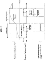
- 111 designates a light source lamp such as a strobe, etc., which can be turned on and off at high speed; 112 a power source for supplying electric power to light source lamp 111; 113 a transmission type display device such as a TFT liquid crystal device, etc., which converts electric image signals into light for image display; 116 a drive circuit for generating drive signals for driving display device 113 in accordance with the image signals and synchronizing signals; and 117 a pulse generating circuit for generating control pulses in synchronism with the vertical synchronization of the input synchronizing signals so as to perform on/off control of power source 112.
- a light source lamp such as a strobe, etc.
- light source lamp 111 is turned off during the period from time t1 to time t2 within one field period T and turned on during the period from time t2 to time t3, by pulsing application of electric power from power source 12 (see Fig. 2).
- the illumination ratio is 25%
- the lamp is turned off during the period from time t1 to time t6 within one field period T and turned on during the period from time t6 to time t3, by pulsing application of electric power from power source 12 (see Fig. 2).
- the illuminating period of light source lamp 111 is controlled by pulse generating circuit 117 and power source 112. Accordingly, total response of image display light for image display is given by the pulse-on waveform from time t2 to time t3 and the pulse-on waveform from time t4 to t5 only, for the case of the illumination ratio of 50%, for instance. Therefore, the temporal spread of total response for display is reduced and the temporal frequency characteristic is also improved to be flatter, so that image quality degradation during displaying motion pictures can be inhibited.
- a full-screen flashing type The technique for suppressing image quality degradation such as blur injury, etc., arising when displaying motion pictures, by illuminating the full screen range with the backlight a predetermined time after data writing of the image signal for one frame to be displayed on the LCD panel is called a full-screen flashing type, which has been also disclosed in, for instance, Japanese Patent Application Laid-open 2001-201763, Japanese Patent Application Laid-open 2002-55657 and others, other than the above-mentioned Japanese Patent Application Laid-open Hei 9-325715.
- scanning type backlighting schemes have been proposed in, for instance, Japanese Patent Application Laid-open Hei 11-202286, Japanese Patent Application Laid-open 2000-321551, Japanese Patent Application Laid-open 2001-296838, in which image quality degradation such as blur injury etc., arising during displaying motion pictures, is suppressed by sequentially activating scan-wise multiple backlight for divided lighting areas that correspond to multiple divided display areas of the LCD panel.
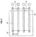
- a multiple number of (four, in this case) direct fluorescent lamps (CCFT) 203 to 206 are arranged parallel to the scan lines, on the backside of a liquid crystal display panel 202, and the lamps 203 to 206 are sequentially activated from top to bottom, in synchronization with the scan signals for liquid crystal display panel 202.
- lamps 203 to 206 correspond to four display areas into which liquid crystal display panel 202 is divided in the horizontal direction.
- Fig. 4 is a chart showing activation timing of the lamps corresponding to Fig. 3.
- the high state presents the lighted state of the lamp.
- the video signal is written into the top one-fourth of the display area of liquid crystal display panel 202, in duration (1) within one frame period, and fluorescent lamp 203 is activated in duration (4) after a delay of durations (2) and (3) for liquid crystal response time.
- the lamps for divided display areas are repeatedly and sequentially activated within one frame period by one after another after writing of the video signal.
- the luminous area corresponding to the backlight is illuminated at a timing when the liquid crystal has been brought to a full optical response, the duration from the time the image is written into the liquid crystal to the time the backlight is activated can be made equal regardless of the position (vertical position) on the display screen.
- this configuration is advantageous in making satisfactory improvement of blur injury in motion pictures regardless of the position on the display screen.
- black insert type liquid crystal displays in which, instead of making intermittent the backlight in one frame period, the video signal and the black signal are alternately written into the liquid crystal display panel in one frame period so that the light emission time of each pixel (image display duration) from the time a certain video signal frame is scanned to the time the next frame is scanned is shortened to realize emulative impulse type display.
- Such black insert type liquid crystal displays include: one in which, as shown in Fig. 6(a), one frame of input image data is sequentially written into the liquid crystal display panel, then the whole screen is written in with black display data so that the display of the whole screen is blackened in a predetermined period; and one in which, as shown in Fig.6(b), part of the screen is displayed with black for a predetermined period so as to shorten the span for displaying the image in one frame period compared to the conventional hold-type display device, by sequentially writing black display data every scan line (Japanese Patent Application Laid-open Hei 9-127917 and Japanese Patent Application Laid-open Hei 11-109921).
- attempts to amend image quality degradation due to blur injury arising when displaying motion pictures in a hold- type display device are made to simulate impulse-type drive display drive as in a CRT or the like, from hold-type drive display drive, by shortening the span of image display, specifically, by implementing intermittent backlight drive within one frame period (e.g., 16.7 msec in the case of 60 Hz progressive scan), or by writing black display data to the liquid crystal display panel after writing of image display data.
- the impulse ratio (the ratio of the image display duration in one frame period) is made lower.
- reduction of the impulse ratio may induce the following problems (1) to (3).
- (1) The extent of the effect of motion blur depends on the image type. For example, in the case of CG (computer graphics), animation and game images, the movie is rendered by a series discrete images (at one moment only within every frame) as shown in Fig. 7(a) though they are supposed to be continuous. That is, there are some cases where no motion blur which will function to interpolate interval between frames is added.
- Smooth motion can be obtained if motion blur is generated and added by an image process.
- a picture without any motion blur i.e. , a content image which originally lacks smoothness in motion is displayed with a low impulse ratio
- a stroboscopic defect i.e., discrete motion of moving objects, occurs, leading to more trouble of image quality degradation.
- Images taken by a storage type camera that is usually used as a television camera have different amounts of motion blur depending on the shutter speeds, because each frame is an accumulation of light while the shutter being open.
- movies and images taken indoors such as in a studio under strong lighting (e.g., news programs, broadcasts of indoor competitions such as swimming races) are taken at high shutter speeds (that is, the opening duration of the shutter is short)
- a moving object is supposed to be added with a small amount of motion blur during shooting, as shown in Fig. 7(b).
- Fig. 7(b) When such an image with a small amount of motion blur is displayed with a low impulse ratio, there is a high possibility of the aforementioned stroboscopic defect occurring.
- an image that is shot dark, outdoors, such as a broadcast of a night game of baseball match or soccer match may be taken at low shutter speeds (that is, the opening duration of the shutter is long).
- a moving object is supposed to be added with a large amount of motion blur during shooting, as shown in Fig. 7(c).
- smooth motion can be reproduced by virtue of motion blur.
- no stroboscopic defect stated above will occur, therefore it is preferred to give priority to display of a sharp and clear motion picture by reducing blur injury.
- the visual characteristics when watching motion pictures is considered to be attributed to ocular movement, time integration of vision and the non-linearity of the visual response to photic stimulation intensity.
- ocular movement the characteristic of the following movement (movement of left and right eyes chasing a moving object approximately similarly), which is the most important characteristic for perceiving motion pictures, varies depending on the speeds of moving objects and the like, and there is a possibility that the aforementioned stroboscopic defect may occur in some image contents when the image is displayed with a low impulse ratio.
- the optimal impulse ratio is different depending on the image contents, image materials and the like. Moreover, sensitivity (dynamic visual acuity) to blur injury, stroboscopic effects and flickering greatly varies between individual users, so that it is impossible to realize improvement of total image quality for individual users.
- the first invention is a liquid crystal display device wherein the image signal to be displayed is written into a liquid crystal display panel while a backlight is activated intermittently within one frame period, comprising: a means for detecting the type of the image content to be displayed; and a means for variably controlling the illumination duration of the backlight based on the detected type of the image content.
- the second invention is characterized in that, in the first invention, the backlight emits a flash of light over the full screen every one frame period in synchronization with the vertical synchronizing signal supplied to the liquid crystal display panel.
- the third invention is characterized in that, in the first invention, the backlight is operated so that multiple luminous sections are activated, one to the next, scan-wise in synchronization with the vertical and horizontal synchronizing signals supplied to the liquid crystal display panel.
- the fourth invention is characterized in that, in the first to third invention, the luminous intensity of the backlight is varied in accordance with the illumination duration of the backlight.
- the fifth invention is characterized in that, in the first to fourth invention, the gray scale levels of the input image signal are varied in accordance with the illumination duration of the backlight.
- the sixth invention is characterized in that, in the first to fourth invention, the gray scale voltages applied to the liquid crystal display panel in response to the input image signal are varied in accordance with the illumination duration of the backlight.
- the seventh invention is characterized in that, in the first to sixth invention, the frame frequency of the input image signal is varied based on the type of the image content.
- the eighth invention is characterized in that, in the first to seventh invention, the type of the image content to be displayed is detected based on the contents information included in the broadcast data.
- the ninth invention is characterized in that, in the first to seventh invention, the type of the image content to be displayed is detected based on the contents information obtained from external media.
- the tenth invention is characterized in that, in the first to seventh invention, the type of the image content to be displayed is detected based on the video source select command information input by the user.
- the eleventh invention is a liquid crystal display device wherein the image signal to be displayed and the black display signal are written into a liquid crystal display panel within one frame period, comprising: a means for detecting the type of the image content to be displayed; and a means for variably controlling the duration in which the black display signal is supplied to the liquid crystal display panel based on the detected type of the image content.
- the twelfth invention is characterized in that, in the eleventh invention, the luminous intensity of the backlight that illuminates the liquid crystal display panel is varied in accordance with the application duration of the black display signal.
- the thirteenth invention is characterized in that, in the eleventh or twelfth invention, the gray scale levels of the input image signal are varied in accordance with the application duration of the black display signal.
- the fourteenth invention is characterized in that, in the eleventh or twelfth invention, the gray scale voltages applied to the liquid crystal display panel in response to the input image signal are varied in accordance with the application duration of the black display signal.
- the fifteenth invention is characterized in that, in the eleventh to fourteenth invention, the type of the image content to be displayed is detected based on the contents information included in the broadcast data.
- the sixteenth invention is characterized in that, in the eleventh to fourteenth invention, the type of the image content to be displayed is detected based on the contents information obtained from external media.
- the seventeenth invention is characterized in that, in the eleventh to fourteenth invention, the type of the image content to be displayed is detected based on the video source select command information input by the user.
- the eighteenth invention is a liquid crystal display device wherein display duration of the image signal and non-display duration are provided in one frame period, comprising: a means for detecting the type of the image content to be displayed; and a means for variably controlling the ratio of the display duration of the image signal in the one frame period, based on the detected type of image content.
- the nineteenth invention is characterized in that, in the eighteenth invention, the gray scale levels of the input image signal are varied in accordance with the illumination duration of the backlight.
- the twentieth invention is characterized in that, in the eighteenth invention, the gray scale voltages applied to the liquid crystal display panel in response to the input image signal are varied in accordance with the illumination duration of the backlight.
- the twenty-first invention is characterized in that, in the eighteenth to twentieth invention, the type of the image content to be displayed is detected based on the contents information included in the broadcast data.
- the twenty-second invention is characterized in that, in the eighteenth to twentieth invention, the type of the image content to be displayed is detected based on the contents information obtained from external media.
- the twenty-third invention is characterized in that, in the eighteenth to twentieth invention, the type of the image content to be displayed is detected based on the video source select command information input by the user.
- the twenty-fourth invention is a liquid crystal display device wherein the image signal to be displayed is written into a liquid crystal display panel while a backlight is activated intermittently within one frame period, comprising: a means for detecting a user's instructional input; and a means for variably controlling the illumination duration of the backlight based on the detected user's instructional input.
- the twenty-fifth invention is characterized in that, in the twenty-fourth invention, the backlight emits a flash of light over the full screen every one frame period in synchronization with the vertical synchronizing signal supplied to the liquid crystal display panel.
- the twenty-sixth invention is characterized in that, in the twenty-fourth invention, the backlight is operated so that multiple luminous sections are activated, one to the next, scan-wise in synchronization with the vertical and horizontal synchronizing signals supplied to the liquid crystal display panel.
- the twenty-seventh invention is characterized in that, in the twenty-fourth to twenty-sixth invention, the luminous intensity of the backlight is varied in accordance with the illumination duration of the backlight.
- the twenty-eighth invention is characterized in that, in the twenty-fourth to twenty-seventh invention, the gray scale levels of the input image signal are varied in accordance with the illumination duration of the backlight.
- the twenty-ninth invention is characterized in that, in the twenty-fourth to twenty-seventh invention, the gray scale voltages applied to the liquid crystal display panel in response to the input image signal are varied in accordance with the illumination duration of the backlight.
- the thirtieth invention is characterized in that, in the twenty-fourth to twenty-ninth invention, the frame frequency of the input image signal is varied based on the user's instruction.
- the thirty-first invention is characterized in that, in the twenty-fourth to thirtieth invention, the illumination duration of the backlight is varied based on the video source select command information input by the user.
- the thirty-second invention is characterized in that, in the twenty-fourth to thirtieth invention, the illumination duration of the backlight is varied based on the video adjustment command information input by the user.
- the thirty-third invention is a liquid crystal display device wherein the image signal to be displayed and the black display signal are written into a liquid crystal display panel within one frame period, comprising: a means for detecting a user's instructional input; and a means for variably controlling the duration in which the black display signal is supplied to the liquid crystal display panel based on the user's instructional input.
- the thirty-fourth invention is characterized in that, in the thirty-third invention, the luminous intensity of the backlight that illuminates the liquid crystal display panel is varied in accordance with the application duration of the black display signal.
- the thirty-fifth invention is characterized in that, in the thirty-third or thirty-fourth invention, the gray scale levels of the input image signal are varied in accordance with the application duration of the black display signal.
- the thirty-sixth invention is characterized in that, in the thirty-third or thirty-fourth invention, the gray scale voltages applied to the liquid crystal display panel in response to the input image signal are varied in accordance with the application duration of the black display signal.
- the thirty-seventh invention is characterized in that, in the thirty-third to thirty-sixth invention, the application duration of the black display signal is varied based on the video source select command information input by the user.
- the thirty-eighth invention is characterized in that, in the thirty-third to thirty-sixth invention, the application duration of the black display signal is varied based on the video adjustment command information input by the user.
- the thirty-ninth invention is a liquid crystal display device wherein display duration of the image signal and non-display duration are provided in one frame period, comprising: a means for detecting a user's instructional input; and a means for variably controlling the ratio of the display duration of the image signal in the one frame period, based on the detected user's instruction.
- the fortieth invention is characterized in that, in the thirty-ninth invention, the gray scale levels of the input image signal are varied in accordance with the ratio of the display duration of the image signal in the one frame period.
- the forty-first invention is characterized in that, in the thirty-ninth invention, the gray scale voltages applied to the liquid crystal display panel in response to the input image signal are varied in accordance with the ratio of the display duration of the image signal in the one frame period.
- the forty-second invention is characterized in that, in the thirty-ninth to forty-first invention, the ratio of the display duration of the image signal in the one frame period is varied based on the video source select command information input by the user.
- the forty-third invention is characterized in that, in the thirty-ninth to forty-first invention, the ratio of the display duration of the image signal in the one frame period is varied based on the video adjustment command information input by the user.
- the backlight illumination duration or the ratio of the image display duration in one frame period is appropriately switched in accordance with the type of the image content to be displayed or in accordance with the user's instruction, whereby it is possible to appropriately control the image quality degradation due to blur injury, stroboscopic effect, flickering and other factors, hence realize total image quality improvement.
- the black display duration or the ratio of the image display duration in one frame period is appropriately switched in accordance with the type of the image content to be displayed or in accordance with the user's instruction, whereby it is possible to appropriately control the image quality degradation due to blur injury, stroboscopic effect, flickering and other factors, hence realize total image quality improvement.
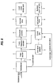
- Fig. 8 is a functional block diagram showing a fundamental schematic configuration of a liquid crystal display of the present embodiment.
- Fig. 9 is an illustrative view for explaining one example of a basic operating mechanism in the liquid crystal display of the present embodiment.
- Fig. 10 is an illustrative view for explaining another example of a basic operating mechanism in the liquid crystal display of the present embodiment.
- the liquid crystal display of the present embodiment includes: as shown in Fig. 8, a demultiplexer 1 for separating images, sound data and control data (contents information, etc.,) from input multiplexed data (transport stream) made up of compression coded images in an MPEG (Moving Picture Expert Group) scheme or the like, sound data and control data and outputting these pieces of data to an image decoder 2, a sound decoder (not shown) and a control CPU 10, respectively; and the image decoder 2 for decoding the separated image data based on MPEG.
- MPEG Motion Picture Expert Group
- the device further includes: a frame frequency converter 3 for converting the frame frequency of the decoded input image signal to a high frequency; a gray scale converter 4 for converting the gray scale levels of the input image signal; an electrode driver 5 for driving the data electrodes and scanning electrodes of a liquid crystal display panel 6 in accordance with the input image signal; and an active-matrix liquid crystal display panel 6.
- the device further includes: a bottom-emitting backlight 7 arranged on the back of the liquid crystal display panel 6; a light source driver 8 for implementing intermittent drive, i.e. , turning on/off the backlight 7 in one vertical display period (one frame period); a synchronizing signal extractor 9 for extracting synchronizing signals from the input image signal decoded through the image decoder 2; and a control CPU 10 which acquires and analyzes contents information from the control data separated through a demultiplexer 1 and outputs a control signal to light source driver 8 so as to control the on/off timing of backlight 7 based on the vertical synchronizing signal extracted through the synchronizing signal extractor 7.
- Control CPU 10 analyzes these so as to detect and determine the type of the content of the image to be displayed, and generates a control signal for varying the backlight illumination duration (image display duration) by referring to a ROM, for example, in which impulse ratio information is stored beforehand for every type of image contents.
- the types of contents indicate the categories such as sport, drama, news, animation, game, etc. If the contents information contained in the aforementioned broadcast data, further includes shooting information descriptive of the shooting conditions such as shutter speed, information as to additional motion blur and the like, other than the EPG (electronic program guide) information descriptive of the program genre, categories and the like, the control CPU 10 is able to detect the content type of the image to be displayed based on this information.
- shooting information descriptive of the shooting conditions such as shutter speed, information as to additional motion blur and the like, other than the EPG (electronic program guide) information descriptive of the program genre, categories and the like
- video source video position
- EPG electronic program guide
- the control CPU 10 also makes control of light source driver 8 so as to vary the luminous brightness of backlight 7 or makes control of gray scale converter 4 so as to vary the gray scale levels of the input image signal as it variably controls the illumination duration of backlight 7 (image display duration).
- the luminous brightness (backlight brightness) of backlight 7 is enhanced while the input image signal levels are converted by gray scale converter 4 so that the input image signal and the display brightness will hold a constant relationship if the illumination duration (illumination ratio) of backlight 7 is reduced.
- Gray scale converter 4 converts the input image signal levels (gray scale levels) in order to effect image display without change of gamma characteristic if the impulse ratio is varied. Specifically, for each impulse ratio, a conversion table (LUT) for converting the input image signal levels (gray scale levels) so that gamma characteristic will not vary has been stored in ROM or the like, and gray scale converter 4 converts the input image signal levels (gray scale levels) with reference to this conversion table. In this way, it is possible to suppress the occurrence of image quality degradation due to change in gamma characteristic.
- LUT conversion table
- the impulse ratio is made lower without change of the luminous brightness of backlight 7, pixels with low brightness values are marred, hence the input image signal levels (gray scale levels) are converted so as to increase the display brightness and enhance the contrast in dark gray scale.
- the impulse ratio is made higher, pixels with high brightness values are marred, hence the input image signal levels (gray scale levels) are converted so as to decrease the display brightness and enhance the contrast in light gray scales.
- control CPU 10 controls frame frequency converter 3, as required, so as to vary the frame frequency of the image signal to be supplied to liquid crystal display panel 6.
- Frame frequency converter 3 for example, having a frame memory, stores one frame of image of the input image signal, into the frame memory, then outputs the image signal of which the frame frequency has been converted into a predetermined value based on the control signal from control CPU 10, to thereby compress the input image signal with respect to the temporal axis.
- bottom-emitting or side-illuminating LED light sources As the backlight 7, other than bottom-emitting fluorescent lamps, bottom-emitting or side-illuminating LED light sources, EL light sources and the like can be used.
- an LED which has a response speed of some tens nsec to some hundreds nsec, is good in response compared to a fluorescent lamp having a response speed of millisecond order, hence is able to achieve more preferable on/off performance for switching.
- the liquid crystal display of the present embodiment is to prevent blur injury arising when displaying motion pictures, using a full-screen flashing type backlight lighting system.
- the whole frame of display has been completely scanned (written with an image), then a drive waveform is applied to backlight 7 after a lapse of a predetermined time, so that backlight 7 is totally lightened at once (made to flash) to illuminate the full screen of the display frame, in the backlight illumination duration indicated by hatching in Fig. 9.
- the backlight illumination duration indicated by hatching in Fig. 9 i.e., the image display duration in one frame period (impulse ratio) is varied based on the type of the image content to be displayed, whereby occurrence of image quality degradation due to blur injury, stroboscopic effect, flickering and other factors is appropriately controlled, thus total image quality improvement is realized.
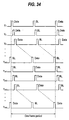
- Figs. 9(a) to (c) show an operational example of switching of the impulse ratio, into three classes, i.e. , 30%, 40% and 50%, respectively, by converting the frame frequency (60Hz) of the input image signal fourfold into 240 Hz through frame frequency converter 3 and variably controlling the backlight illumination duration.
- backlight 7 is activated after a lapse of a period of time (here 45% of one frame period) sufficiently longer than the predetermined liquid crystal response time, then is kept lit for the backlight illumination duration (image display duration) until the image write-scan of the next frame starts.
- the impulse ratio is set to be 30% and it is possible to realize sharp and clear motion picture display by preventing occurrence of blur injuries as well as to render smooth motion of moving objects with a certain amount of motion blur.
- an input image content is, for example, a movie or one that was shot under strong lighting in a studio or the like (e.g., news programs, broadcasts of indoor competitions such as swimming races)(see Fig. 7(b))
- the material was likely taken at high shutter speeds, entailing a small amount of motion blur. Therefore, there is a possibility of image quality defects such as stroboscopic effect, flickering and others occurring if the impulse ratio is set small.
- the impulse ratio is set to be 40% and it is possible to reproduce smooth motion of moving objects by preventing occurrence of blur injuries while suppressing occurrence of image quality defects such as stroboscopic effect, flickering and the like.
- backlight 7 is activated immediately after a lapse of just the predetermined liquid crystal response time (in this case, 25% of one frame period), then is kept lit for the backlight illumination duration (image display duration) until the image write-scan of the next frame starts.
- the impulse ratio is set to be 50% and it is possible to reproduce smooth motion of moving objects by suppressing occurrence of blur injuries while preventing occurrence of image quality defects such as stroboscopic effect, flickering and the like.
- the backlight illumination duration (image display duration) is varied by delaying the time at which the backlight is turned on or by bringing forward the time at which the backlight is turned off, in accordance with the type of the image content to be displayed.
- the frame frequency of the display image signal is fixed (240 Hz).
- control CPU 10 to control frame frequency converter 3 so as to vary the frame frequency of the display image signal while varying the backlight illumination duration, such as in Fig.10.
- the frame frequency of the input image signal is converted fourfold into 240 Hz so that the image write-scanning duration is 25% of one frame period, and after the image write-scan has been completed, backlight 7 is activated after a lapse of the predetermined liquid crystal response time (here 25% of one frame period), then is kept lit for the backlight illumination duration (image display duration) until the image write-scan of the next frame starts.
- the impulse ratio is set to be 50% and it is possible to realize sharp and clear display of motion pictures by preventing occurrence of blur injuries as well as to render smooth motion of moving objects with a certain amount of motion blur.
- an input image content is, for example, a motion picture or one that was shot under strong lighting in a studio or the like (e.g., news programs, broadcasts of indoor competitions such as swimming races)(see Fig. 7(b))
- the material was likely taken at high shutter speeds, entailing a small amount of motion blur. Therefore, there is a possibility of image quality defects such as stroboscopic effect, flickering and others occurring if the impulse ratio is set small.
- the frame frequency of the input image signal is converted eightfold into 480 Hz so as to reduce the image write-scanning duration to 25% of one frame period, and after the image write-scan has been completed, backlight 7 is activated after a lapse of the predetermined liquid crystal response time (here 25% of one frame period), so that the backlight illumination duration (image display duration) is increased.
- the impulse ratio is set to be 62.5% and it is possible to reproduce smooth motion of moving objects by preventing occurrence of blur injuries while suppressing occurrence of image quality defects such as stroboscopic effect, flickering and the like.
- an input image content is one that is free from motion blur such as CG (computer graphics), animation, games and the like (see Fig. 7(a))
- CG computer graphics
- animation animation
- games and the like there is a high possibility of image quality defects such as stroboscopic effect, flickering and others occurring if the impulse ratio is set small.
- the backlight illumination duration (image display duration) in one frame period is varied in accordance with the type of the image content to be displayed, whereby it is possible to appropriately inhibit image quality degradation due to blur injury, stroboscopic effect, flickering and other factors, hence realize total improvement in image quality. Further, it is also possible to further improve the variable flexibility of the impulse ratio in accordance with the size, response characteristic etc., of liquid crystal display panel 6 in combination with the example shown in Fig. 9.
- the above embodiment is configured so that the backlight illumination duration, or the image display duration in one frame period (impulse ratio) can be switched to three classes including the full hold type display mode (impulse ratio : 100%), in accordance with the types of image contents.
- the present invention should not be limited to this. It goes without saying that the present invention can be realized as long as the impulse ratio can be switched between two or more predetermined values, in accordance with the type of the image content. For example, it is possible to construct a simple configuration in which the display is simply switched between the impulse type display mode and the hold type display mode, (i.e., the impulse-type display mode off), in an alternative manner.
- the EPG electronic program guide
- the EPG electronic program guide
- the input image content can be obtained, based on this information it is possible to determine the type of the image content to be displayed.
- the image display device of this kind is configured so that the user is able to select the input video source (video position) through a menu setting frame.
- This information as to the input video source selection designated by the user may also be used to determine the type of the image content to be displayed to thereby variably control the impulse ratio.
- "game” is selected and designated as the selection item of the video source (video position) through the menu setting frame, it is possible to switch and set the impulse ratio to a high value in link with this selection.
- the impulse ratio is variably controlled by determining the type of the image content to be displayed with reference to the user's instructional information concerning video adjustment items.
- the liquid crystal display of the present embodiment is able to appropriately control the image quality degradation due to blur injury, stroboscopic effect, flickering and other factors, hence realize total image quality improvement, by suitably switching the backlight illumination duration or the ratio of the image display duration in one frame period (impulse ratio), in a configuration that simulates impulse-type drive display using full-screen flashing type backlight illumination.
- backlight brightness can be varied in accordance with the illumination duration of backlight 7 in one frame period (impulse ratio) while the gray scale levels of the input image signal are converted through gray scale converter 4, it is possible to always keep the relationship between the input image signal and the display brightness constant regardless of the impulse ratio.
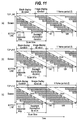
- Fig. 11 is an illustrative view for explaining one example of a basic operating mechanism in the liquid crystal display of the present embodiment
- Fig. 12 is an illustrative view for explaining another example of a basic operating mechanism in the liquid crystal display of the present embodiment.
- the liquid crystal display of the present embodiment is to prevent blur injury arising when displaying motion pictures, with scanning type backlight illumination, and the basic functional block diagram is much the same as the first embodiment described above with reference to Fig. 1.
- the difference is that a multiple number of bottom-emitting fluorescent lamps disposed parallel to the scan lines, or a multiple number of bottom-emitting or side-illuminating LED light sources or EL light sources, or others are used to constitute a backlight 7, and the light source is divided into luminous sections every predetermined number so that these sections are controlled to sequentially illuminate scan-wise in one frame period.
- Control CPU 10 controls the timing of activating scan-wise the luminous sections one to another in the backlight, based on the vertical/horizontal synchronizing signals (scan signals) extracted through synchronizing signal extractor 9 and the contents information contained in the control data that was separated through demultiplexer 1.
- a certain group of horizontal lines (divided display section) has been completed, then the luminous section (made of a group of fluorescent lamps or a group of LEDs) of backlight 3 corresponding to the group of horizontal lines is activated taking into account a lapse of the LC response delay. This process is repeated one to the next in the vertical direction. In this way, it is possible to sequentially shift the backlight illumination duration corresponding to the write-scanning section of the image signal, from one luminous section to the next with the passage of time, as indicated by hatching in Fig. 11.
- the backlight illumination duration of each luminous section indicated by hatching in Fig. 11, or the image display duration in one frame period (impulse ratio), is varied based on the type of the image content to be displayed, whereby image quality degradation arising depending on the type of the image content due to blur injury, stroboscopic effect, flickering and other factors is appropriately controlled, thus total image quality improvement is realized.
- control CPU 10 makes control of light source driver 8 so as to vary the luminous brightness of backlight 7 or makes control of gray scale converter 4 so as to vary the gray scale levels of the input image signal as it variably controls the illumination duration of backlight 7 (image display duration).
- the luminous brightness (backlight brightness) of backlight 7 is enhanced while the input image signal levels are converted by gray scale converter 4 so that the input image signal and the display brightness will hold a constant relationship if the illumination duration (illumination ratio) of backlight 7 is reduced.
- Gray scale converter 4 converts the input image signal levels (gray scale levels) in order to effect image display without change of gamma characteristic if the impulse ratio is varied. Specifically, for each impulse ratio, a conversion table (LUT) for converting the input image signal levels (gray scale levels) so that gamma characteristic will not vary has been stored in ROM or the like, and gray scale converter 4 converts the input image signal levels (gray scale levels) with reference to this conversion table. In this way, it is possible to suppress the occurrence of image quality degradation due to change in gamma characteristic.
- LUT conversion table
- control CPU 10 controls frame frequency converter 3, as required, so as to very the frame frequency of the image signal to be supplied to liquid crystal display panel 6.
- Frame frequency converter 3 having, for example, a frame memory, stores one frame of image of the input image signal, into the frame memory, then outputs the image signal of which the frame frequency has been converted into a predetermined frame frequency based on the control signal from control CPU 10, to thereby compress the input image signal with respect to the temporal axis.
- Figs. 11(a) to (c) show an operational example of switching of the image display duration in one frame period, into three classes, i.e., 3/8 frame period, 1/2 frame period and 5/8 frame period, respectively, by variably controlling the timing at which backlight illumination for each luminous section of backlight 7 is activated, without change of the frame frequency (60Hz) of the input image signal.
- a period of time here, a 1/2 frame period
- the luminous section of backlight 7 corresponding to the group of horizontal lines is activated and kept lit for the backlight illumination duration (image display duration) until the image write-scan of the next frame starts.
- the impulse ratio is set to be 37.5% and it is possible to realize sharp and clear display of motion pictures by preventing occurrence of blur injuries as well as to render smooth motion of moving objects with a certain amount of motion blur.
- an input image content is, for example, a motion picture or one that was shot under strong lighting in a studio or the like (e.g., news programs, broadcasts of indoor competitions such as swimming races)(see Fig. 7(b))
- the material was likely taken at high shutter speeds, entailing a small amount of motion blur. Therefore, there is a possibility of image quality defects such as stroboscopic effect, flickering and others occurring if the impulse ratio is set small.
- the impulse ratio is set to be 50% and it is possible to reproduce smooth motion of moving objects by preventing occurrence of blur injuries while suppressing occurrence of image quality defects such as stroboscopic effect, flickering and the like.
- an input image content is one that is free from motion blur such as CG (computer graphics), animation, games and the like (see Fig. 7(a))
- CG computer graphics
- animation animation
- games and the like there is a high possibility of image quality defects such as stroboscopic effect, flickering and others occurring if the impulse ratio is set small.
- the impulse ratio is set to be 62.5% and it is possible to reproduce smooth motion of moving objects by preventing occurrence of blur injuries while suppressing occurrence of image quality defects such as stroboscopic effect, flickering and the like.
- the backlight illumination duration (image display duration) is varied by delaying the time at which backlight for each luminous section is turned on or by bringing forward the time at which backlight is turned off, in accordance with the type of the image content to be displayed.
- the frame frequency of the display image signal is fixed (60 Hz).
- control CPU 10 to control frame frequency converter 3 so as to vary the frame frequency of the display image signal while varying the backlight illumination duration, as shown in Fig.12, for example.
- Fig. 12(a) With no frame frequency conversion of the input image signal implemented, image write-scan for a certain group of horizontal lines has been completed, then after a lapse of just the predetermined liquid crystal response time (here, a 1/4 frame period), the luminous section of backlight 7 corresponding to the group of horizontal lines is activated and kept lit for the backlight illumination duration (image display duration) until the image write-scan of the next frame starts.
- the impulse ratio is set to be 62.5% and it is possible to realize sharp and clear display of motion pictures free from occurrence of blur injuries and reproduce smooth motion of moving objects with a certain amount of motion blur.
- an input image content is, for example, a motion picture or one that was shot under strong lighting in a studio or the like (e.g., news programs, broadcasts of indoor competitions such as swimming races)(see Fig. 7(b))
- the material was likely taken at high shutter speeds, entailing a small amount of motion blur. Therefore, there is a possibility of image quality defects such as stroboscopic effect, flickering and others occurring if the impulse ratio is set small.
- the frame frequency of the input image signal is converted fourfold into 240 Hz so as to reduce the image write-scanning duration to a 1/4 frame period, and image write-scan for a certain group of horizontal lines has been completed, then after just a lapse of a period of time (here, a 1/4 frame period) longer than the predetermined liquid crystal response time, the luminous section of backlight 7 corresponding to the group of horizontal lines is activated so that the backlight illumination duration (image display duration) is increased.
- the impulse ratio is set to be about 72% and it is possible to reproduce smooth motion of moving objects by preventing occurrence of blur injuries while suppressing occurrence of image quality defects such as stroboscopic effect, flickering and the like.
- an input image content is one that is free from motion blur such as CG (computer graphics), animation, games and the like (see Fig. 7(a))
- CG computer graphics
- animation animation
- games and the like there is a high possibility of image quality defects such as stroboscopic effect, flickering and others occurring if the impulse ratio is set small.
- the backlight illumination duration (image display duration) in one frame period is varied in accordance with the type of the image content to be displayed, whereby it is possible to appropriately inhibit image quality degradation due to blur injury, stroboscopic effect, flickering and other factors, hence realize total improvement in image quality. Further, it is also possible to further improve the variable flexibility of the impulse ratio in accordance with the size, response characteristic etc., of liquid crystal display panel 6 in combination with the example shown in Fig. 11.
- the above embodiment is configured so that the backlight illumination duration (image display duration) in one frame period, i.e., the impulse ratio, can be switched to three classes including the full hold type display mode (impulse ratio : 100%), in accordance with the types of image contents.
- the present invention should not be limited to this. It goes without saying that the present invention can be realized as long as the impulse ratio can be switched between two or more predetermined values, in accordance with the type of the image content. For example, it is possible to construct a simple configuration in which the display is simply switched between the impulse type display mode and the hold type display mode, (i.e., the impulse-type display mode off), in an alternative manner.
- theEPG electronic program guide
- the input image content can be obtained, based on this information it is possible to determine the type of the image content to be displayed.
- the image display device of this kind is configured so that the user is able to select the input video source (video position) through a menu setting frame.
- This information as to the input video source selection designated by the user may also be used to determine the type of the image content to be displayed to thereby variably control the impulse ratio.
- "game” is selected and designated as the selection item of the video source (video position) through the menu setting frame, it is possible to switch and set the impulse ratio to a high value in link with this selection.
- the impulse ratio is variably controlled by determining the type of the image content to be displayed with reference to the user's instructional information concerning video adjustment items.
- backlight 7 is divided into eight luminous sections (groups of horizontal lines) so that the sections are sequentially illuminated scan-wise.
- the backlight may be divided into any number of luminous sections as long as it is divided into two or more.
- backlight 3 is not necessarily divided into horizontal strips (parallel to the scan lines) of luminous sections.
- use of a bottom-emitting planar LED device as a backlight 7 can afford improved flexibility for designing the divided luminous sections, compared to the others.
- use of a LED device as a backlight 7 also makes it possible to control the backlight brightness relatively easily by regulating its drive current.
- the liquid crystal display of the present embodiment is able to appropriately control the image quality degradation due to blur injury, stroboscopic effect, flickering and other factors, hence realize total image quality improvement, by suitably switching the backlight illumination duration of each luminous section, or the ratio of the image display duration in one frame period (impulse ratio) in accordance with the type of image content, in a configuration that simulates impulse-type drive display using scanning type backlight illumination.
- backlight brightness can be varied in accordance with the illumination duration of backlight 7 in one frame period (impulse ratio) while the gray scale levels of the input image signal are converted through gray scale converter 4, it is possible to always keep the relationship between the input image signal and the display brightness constant regardless of the impulse ratio.
- Fig. 13 is a functional block diagram showing a fundamental schematic configuration of a liquid crystal display of the present embodiment
- Fig. 14 is a timing chart for explaining an electrode drive operation in a liquid crystal display of the present embodiment
- Fig. 15 is an illustrative view for explaining one example of a basic operating mechanism in a liquid crystal display of the present embodiment.
- the liquid crystal display of this embodiment is to prevent blur injuries arising when displaying motion pictures by the black insertion scheme, or by writing the image display signal scan-wise and subsequently writing the black display signal scan-wise (resetting scan) into liquid crystal display panel 16 within one frame period with backlight 7 constantly activated (continuous illumination), as shown in Fig. 14, and is characterized in that control CPU 10 variably controls the timing when the black display signal is written by electrode driver 5, based on the type of the image content.
- electrode driver 5 selects each scan line for image display and selects the same line once again for black display. In time with these selections, the driver provides the input image signal and black display signal to every data line. This series of operations is performed in a cycle of one frame period. Thus, the duration for displaying the black signal (black display duration) is generated between one frame of image display and the next frame of image display.
- the write-timing (delay time) of the black display signal relative to the write-timing of the image signal is varied in accordance with the image contents type determined by control CPU 10.
- control CPU 10 further makes control of light source driver 8 so as to vary the luminous brightness of backlight 7 or makes control of gray scale converter 4 so as to vary the gray scale levels of the input image signal.
- the luminous brightness (backlight brightness) of backlight 7 is enhanced while the input image signal levels are converted by gray scale converter 4 so that that the input image signal and the display brightness will hold a constant relationship if the image display duration is shortened.
- gray scale converter 4 converts the input image signal levels (gray scale levels) in order to effect image display without change of gamma characteristic if the impulse ratio is varied. Specifically, for each impulse ratio, a conversion table (LUT) for converting the input image signal levels (gray scale levels), so that gamma characteristic will not vary, has been stored in ROM or the like, and gray scale converter 4 converts the input image signal levels (gray scale levels) with reference to this conversion table. In this way, it is possible to suppress the occurrence of image quality degradation due to change in gamma characteristic.
- LUT conversion table
- Fig. 14 is a timing chart for the scan lines (gate lines) of liquid crystal display panel 6.
- gate lines Y1 to Y480 are enabled from one to the next with a short period of time shifted, in one frame period. When all of 480 gate lines have been enabled to write the image signal into the pixel cells, one frame period completes.
- gate lines Y1 to Y480 are enabled once again, after a delay time, which is determined based on the type of the image content, from when each line is first enabled for writing the image signal, so that a voltage displaying black is supplied to every pixel cell through data lines X.
- every pixel cell is set into the black display state. That is, each gate line Y is set into the high level, twice, at different times within one frame period.
- each pixel cell displays image data for a fixed period of time, then the pixel cell is forced to make black display at the following, second selection.
- Figs. 15(a) to (c) show an operational example of switching of the image display duration in one frame period, into three classes, i.e., 1/4 frame period, 1/2 frame period and 1 frame period, respectively, by variably controlling the timing at which the black display signal is written in without change of the frame frequency (60Hz) of the input image signal.
- the impulse ratio is set to be 25% and it is possible to realize sharp and clear display of motion pictures by preventing occurrence of blur injuries as well as to render smooth motion of moving objects with a certain amount of motion blur.
- an input image content is, for example, a motion picture or one that was shot under strong lighting in a studio or the like (e.g., news programs, broadcasts of indoor competitions such as swimming races)(see Fig. 7(b))
- the material was likely taken at high shutter speeds, entailing a small amount of motion blur. Therefore, there is a possibility of image quality defects such as stroboscopic effect, flickering and others occurring if the impulse ratio is set small.
- writing of the image display signal into a certain pixel has been completed, then writing of the black display signal is started after a lapse of a 1/2 frame period, and the black display is kept (for a 1/2 frame period) until the image write-scan of the next frame starts.
- This setting increases the image display duration and determines the impulse ratio to be 50% thus making it possible to reproduce smooth motion of moving objects by preventing occurrence of blur injuries while suppressing occurrence of image quality defects such as stroboscopic effect, flickering and the like.
- an input image content is one that is free from motion blur such as CG (computer graphics), animation, games and the like (see Fig. 7(a))
- CG computer graphics
- animation animation
- games and the like there is a high possibility of image quality defects such as stroboscopic effect, flickering and others occurring if the impulse ratio is set small.
- Fig. 15(c) control is made such that no write scan of the black display signal is implemented or no black display duration is provided (the image display duration is kept for one frame period).
- the impulse ratio is switched to be 100% (full hold-type display mode), so that it is possible to reproduce smooth motion of moving objects (image quality defects such as stroboscopic effect, flickering etc. , will be alleviated as moving objects blur).
- the duration of the black display signal application i.e., the image display duration is varied in accordance with the image content to be displayed, whereby it is possible to appropriately inhibit image quality degradation due to blur injury, stroboscopic effect and other factors, hence realize total improvement in image quality.
- the above embodiment is configured so that the image display duration in one frame period, or the impulse ratio can be switched to three classes including the full hold type display mode (impulse ratio: 100%), in accordance with the types of image contents.
- the present invention should not be limited to this. It goes without saying that the present invention can be realized as long as the impulse ratio can be switched between two or more predetermined values, in accordance with the type of the image content. For example, it is possible to construct a simple configuration in which the display is simply switched between the impulse type display mode and the hold type display mode (i.e., the impulse type display mode off), in an alternative manner.
- the EPG electronic program guide
- the EPG electronic program guide
- the input image content can be obtained, based on this information it is possible to determine the type of the image content to be displayed.
- the image display device of this kind is configured so that the user is able to select the input video source (video position) through a menu setting frame.
- This information as to the input video source selection designated by the user may also be used to determine the type of the image content to be displayed to thereby variably control the impulse ratio.
- "game” is selected and designated as the selection item of the video source (video position) through the menu setting frame, it is possible to switch and set the impulse ratio to a high value in link with this selection.
- the impulse ratio is variably controlled by determining the type of the image content to be displayed with reference to the user's instructional information concerning video adjustment items.
- the input display image signal is supplied directly to liquid crystal display panel 16 without change of its frame frequency (60 Hz).
- frame frequency of the image signal can be varied.
- backlight 7 may be adapted to turn off during the black display duration so as to reduce the backlight illumination duration, whereby it is possible to lengthen the life of backlight 7 and realize low power consumption.
- use of an LED device as backlight 7 also makes it possible to control the backlight brightness relatively easily by regulating its drive current.
- the liquid crystal display of the present embodiment is able to appropriately control the image quality degradation due to blur injury, stroboscopic effect, flickering and other factors, hence realize total image quality improvement, by suitably switching the ratio of the image display duration in one frame period or impulse ratio in accordance with the type of image content, in a configuration that simulates impulse-type drive display using a black insertion display scheme.
- backlight brightness can be varied in accordance with the image display duration in one frame period (impulse ratio) while the gray scale levels of the input image signal are converted through gray scale converter 4, it is possible to always keep the relationship between the input image signal and the display brightness constant regardless of the impulse ratio.
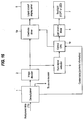
- Fig. 16 is a functional block diagram showing a fundamental schematic configuration of a liquid crystal display of the present embodiment
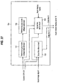
- Fig. 17 is a functional block diagram showing an electrode driver in the present embodiment
- Fig. 18 is a schematic illustrative chart showing a content example of a data storage of reference gray scale voltage data in a liquid crystal display of the present embodiment
- Fig. 19 is an illustrative chart showing one example of the relationship between the transmittance and the appliedvoltage to the liquid crystal
- Fig. 16 is a functional block diagram showing a fundamental schematic configuration of a liquid crystal display of the present embodiment
- Fig. 17 is a functional block diagram showing an electrode driver in the present embodiment
- Fig. 18 is a schematic illustrative chart showing a content example of a data storage of reference gray scale voltage data in a liquid crystal display of the present embodiment
- Fig. 19 is an illustrative chart showing one example of the relationship between the transmittance and the appliedvoltage to the liquid crystal
- Fig. 16 is
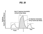
- Fig. 20 is a schematic illustration showing the liquid crystal response characteristic in a liquid crystal display of the present embodiment
- Fig. 21 is a block diagram showing a schematic configuration of a reference gray scale voltage generator in a liquid crystal display of the present embodiment
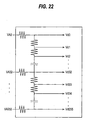
- Fig. 22 is a circuit diagram showing a fundamental schematic configuration of a signal line drive circuit in a liquid crystal display of the present embodiment
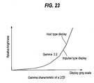
- Fig. 23 is a schematic illustrative view showing gamma characteristics at hold-type display and at impulse-type display in a liquid crystal display of the present embodiment.
- This embodiment is to prevent blur injuries arising when displaying motion pictures, by the black insertion scheme, or by writing the image display signal scan-wise and subsequently writing the black display signal scan-wise (resetting scan) into liquid crystal display panel 6 within one frame period with backlight 7 constantly activated (continuous illumination), basically similarly to the third embodiment, and is characterized in that control CPU 10 variably controls the timing when the black display signal is written by an electrode driver 5a, based on the type of the image content.
- gray scale converter 4 implements conversion with reference to the conversion table, in order to keep the gamma characteristic substantially unchanged.
- no gray scale converter 4 is provided as shown in Fig. 16, and electrode driver 5a, instead of gray scale converter 4, varies the gray scale voltages to be applied to liquid crystal display panel 6 in accordance with the impulse ratio so as to keep the gamma characteristic substantially unchanged.
- control CPU 10 makes control of light source driver 8 so as to vary the luminous brightness of backlight 7 or makes control of electrode driver 5a so as to vary the gray scale voltages applied to liquid crystal display panel 6.
- the luminous brightness (backlight brightness) of backlight 7 is enhanced while the gray scale voltages applied to liquid crystal display panel 6 are varied by electrode driver 5a so that the input image signal and the display brightness will hold a constant relationship if the image display duration is shortened.
- this electrode driver 5a is composed of a reference gray scale voltage data storage 31, a reference gray scale voltage generator 32, a scan line drive circuit 33 and a signal line drive circuit 34.
- the scan signal to be supplied from scan line drive circuit 33 to a scan line (gate line Y) of liquid crystal display panel 6 has two scan line select durations in one frame period, namely, the image display select duration for writing a gray scale voltage corresponding to the image display signal into the pixel electrode and the black display select duration for writing the voltage corresponding to the black display signal into the pixel electrode.
- each gate line Y is set into the high level twice at different times within one frame period.
- signal line drive circuit 34 outputs a gray scale voltage corresponding to the image display signal and the voltage corresponding to the black display signal, alternately, to liquid crystal display panel 6 through each signal line (data line X). In this way, each pixel cell displays the image display signal for a fixed period of time at the first selection, then the pixel cell is forced to make black display at the following, second selection.
- the black display select duration is supposed to be selected in accordance with the impulse ratio, and black display is supposed to be effected for the scan line above or below, by some multiple scan lines, the scan line of which the image display select duration is being selected.
- the signal line which is within the black display select duration is applied with the voltage corresponding to the black display signal so that black display can be made for every scan line.
- the selection of the line to which the black display signal is written in and the line to which the image display signal is written in is made by a scan line drive circuit 33, which is appropriately controlled by control CPU 10.
- the line to be written in with the image display signal and the line to be written in with the black display signal are successively scanned with an interval of multiple lines kept therebetween, one above and the other below.
- signal line drive circuit 34 supplies signals to liquid crystal display panel 6 so that the image display signal for the image display select duration is given to one line (row) while the black display signal for the black display select duration is given to another line(row).
- the input image signal is supplied to signal line drive circuit 34 while scan line drive circuit 33 is controlled by control CPU 10 so that every line is scanned in one frame period (no black display signal is written in). Thereby, it is possible to implement normal hold type display having an impulse ratio of 100%.
- Reference gray scale voltage generator 32 supplies a reference gray scale voltage to signal line drive circuit 34 based on the reference gray scale voltage data stored in reference gray scale voltage data storage 31.
- reference gray scale voltage data storage 31 stores sets of reference voltage data for different impulse ratios, as shown in Fig. 18, (here, the sets for an impulse ratio of 100% corresponding to hold type display and for an impulse type display with an impulse ratio of 50% are shown), in separate ROM areas.
- Control CPU 10 selects and designates one from these and outputs it to reference gray scale voltage generator 32.
- the reference gray scale voltage data stored in reference gray scale voltage data storage 31 is set up in the following manner.
- the reference gray scale voltage data for hold type display (impulse ratio : 100%) is determined so that, based on the relationship between the applied voltage and the liquid crystal transmittance, or the so-called V-T curve, shown in Fig. 19, the relationship between the display gray scale and the display brightness (liquid crystal transmittance) will be equivalent to the gamma 2.2 relationship, for example.
- the display signal levels or the display data is represented by 8 bits or 256 gray scales
- the voltage data V0, V32, ..., V255 corresponding to gray scale levels 0, 32, 64, 96, 128, 160, 192, 224 and 255 are set up and stored.
- the voltage data for the gray scales other than these stored reference gray scales is set by linear resistance division using the above reference gray scale voltages.
- all the gray scale voltages to be applied to liquid crystal display panel 6 can be determined.
- the reference gray scale voltage data for implementing impulse type display cannot be determined directly from the V-T curve shown in Fig. 19, but should be determined by determining the relationship between the applied voltage T to the liquid crystal and the integral I of the brightness over one frame period, the display brightness (transmittance) varying with time at the impulse type display shown in Fig. 20.
- the brightness integral I varies depending on the liquid crystal response speed.
- the relationship between the applied voltage and liquid crystal transmittance (brightness) shown in Fig. 19 will not hold. This means that the gray scale voltages determined from the V-T curve of Fig. 19 for implementation of hold type display are not able to provide desired gray scale representation.
- the relationship between the integral I of the brightness over one frame period and the appliedvoltage need to be measured from the beginning to set up reference gray scale voltage data different from that for the hold type display.
- Setting of the reference gray scale voltage data is implemented so that the relationship between the display gray scale level and the integral I of display brightness (liquid crystal transmittance) will be equivalent to the gamma 2.2 relationship, for example.
- the display signal level or the display data is represented by 8 bits or 256 gray scales
- the voltage data V0, V32, ⁇ , V255 corresponding to gray scale levels 0, 32, 64, 96, 128, 160, 192, 224 and 255 are set up and stored.
- the voltage data for the gray scales other than these stored reference gray scales is set by linear resistance division using the above reference gray scale voltages.
- Reference gray scale voltage generator 32 converts digital data V0, V32, ..., V255 obtained from reference gray scale voltage data storage 31 into analog data through DA converters 51, then amplifies them as appropriate through respective amplifiers 52, to supply the adjusted reference gray scale voltages VA0, VA32, ⁇ , VA255 to signal line drive circuit 34 including source drivers, etc.
- signal line drive circuit 34 as shown in Fig. 22, the input terminals of reference gray scale voltages VA0, VA32, ..., VA255 are connected by voltage-dividing resistors so as to generate all the gray scale voltages corresponding to the image display signal. Thus it is possible to effect display of the 8 bit image display signal.
- gray scale voltages for nine reference gray scales, every 32 steps apart specifically, gray scale levels 0, 32, 64, 96, 128, 160, 192, 224 and 255, are generated and the gray scale voltages other than these are produced by resistor division.
- generation of gray scale voltages is not limited to this. It goes without saying that gray scale voltages may be generated for reference gray scales every 16 steps apart, for example.
- reference gray scale voltage data stored in reference gray scale voltage data storage 31 for implementing hold type display (impulse ratio: 100%) or that for implementing impulse type display (impulse ratio: 50%) is read out by reference gray scale voltage generator 32, and based on the reference gray scale voltage data, and the gray scale voltage, corresponding to each gray scale level of the input image signal, to be applied to liquid crystal display panel 6 is determined.
- the way in which the impulse ratio is varied based on the type of the image content to be displayed is the same as that shown in the third embodiment, so that detailed description is omitted.
- the image data supplied to control CPU 10 is, after all, in effect bit compressed, so there is a risk of the display performance degrading as a result of gray scale conversion.
- Fig. 24 is a functional block diagram showing a fundamental schematic configuration of a liquid crystal display of the present embodiment
- Figs. 25 to 27 are illustrative views for explaining basic operating mechanisms of a liquid crystal display of the present embodiment
- Fig. 28 is an illustrative view showing an example of a switching operation of the impulse ratio in a liquid crystal display of the present embodiment
- Fig. 29 is an illustrative view showing an example of a set frame for switching the impulse ratio in a liquid crystal display of the present embodiment.
- This embodiment as illustrated in Fig. 24, includes:
- the embodiment further includes: a frame frequency converter 13 for converting the frame frequency of the input image signal into a high frequency; a gray scale converter 14 for converting the gray scale levels of the input image signal; a synchronizing signal extractor 19 for extracting synchronizing signals from the input image signal; a remote-control light receiver 21 for receiving command signals input through an unillustratedR/C device (remote-controller) by the user; and a control CPU 20 which detects and analyzes the command signal received by R/C light receiver 21 and outputs a control signal to light source driver 18 for controlling the on/off timing of backlight 17 based on the vertical synchronizing signal extracted through the synchronizing signal extractor 19.
- a frame frequency converter 13 for converting the frame frequency of the input image signal into a high frequency
- a gray scale converter 14 for converting the gray scale levels of the input image signal
- a synchronizing signal extractor 19 for extracting synchronizing signals from the input image signal
- a remote-control light receiver 21 for receiving command signals input through an un
- the control CPU 20 also makes control of light source driver 18 so as to vary the luminous brightness of backlight 17 or makes control of gray scale converter 14 so as to vary the gray scale levels of the input image signal as it variably controls the illumination duration of backlight 17 (image display duration).
- the luminous brightness (backlight brightness) of backlight 17 is enhanced while the input image signal levels are converted by gray scale converter 14 so that that the input image signal and the display brightness will hold a constant relationship if the illumination duration (illumination ratio) of backlight 17 is reduced.
- Gray scale converter 14 converts the input image signal levels (gray scale levels) in order to effect image display without change of gamma characteristic if the impulse ratio is varied. Specifically, for each impulse ratio, a conversion table (LUT) for converting the input image signal levels (gray scale levels) so that gamma characteristic will not vary has been stored in ROM or the like, and gray scale converter 14 converts the input image signal levels (gray scale levels) with reference to this conversion table. In this way, it is possible to suppress the occurrence of image quality degradation due to change in gamma characteristic.
- LUT conversion table
- the impulse ratio is made lower without change of the luminous brightness of backlight 7, pixels with low brightness values are marred, hence the input image signal levels (gray scale levels) are converted so as to increase the display brightness and enhance the contrast in dark gray scales.
- the impulse ratio is made higher, pixels with high brightness values are marred, hence the input image signal levels (gray scale levels) are converted so as to decrease the display brightness and enhance the contrast in light gray scales.
- control CPU 20 controls frame frequency converter 13, as required, so as to very the frame frequency of the image signal to be supplied to liquid crystal display panel 16.
- Frame frequency converter 13 for example, having a frame memory, stores one frame of image of the input image signal, into the frame memory, then outputs the image signal of which the frame frequency has been converted into a predetermined value based on the control signal from control CPU 20, to thereby compress the input image signal with respect to the temporal axis.
- LED light sources As the backlight 17, other than bottom-emitting fluorescent lamps, bottom-emitting or side-illuminating LED light sources, EL light sources and the like can be used.
- an LED which has a response speed of some tens nsec to some hundreds nsec, is good in response compared to a fluorescent lamp having a response speed of millisecond order, hence is able to achieve more preferable on/off performance for switching.
- the liquid crystal display of the present embodiment is to prevent blur injury arising when displaying motion pictures, using a full-screen flashing type backlight lighting system.
- the whole frame of display has been completely scanned (written with an image), then a drive waveform is applied to backlight 17 after a lapse of a predetermined time, so that backlight 17 is totally lighted at once (made to flash) to illuminate the full screen of the display frame, in the backlight illumination duration indicated by hatching in Figs. 25 to 27.
- the backlight illumination duration indicated by hatching in Figs. 25 to 27, i.e. , the image display duration in one frame period (impulse ratio) is varied based on the instruction input through the R/C device (not shown) by the user, whereby image quality degradation occurring depending on the image contents type, details of the image, as a result of blur injury, stroboscopic effect, flickering and other factors, is appropriately controlled, thus total image quality improvement for the user can be realized.
- Figs. 25(a) to (c) show an operational example of variable control of the impulse ratio, into three classes, i.e., 50%, 40% and 30%, respectively.
- image quality degradation due to stroboscopic effect and flickering needs to be reduced, as shown in Fig. 25(a) the image scanning has been completed, then immediately after a lapse of just the predetermined liquid crystal response time (here, a 1/4 frame period), backlight 17 is activated and kept lit for the backlight illumination duration (image display duration) until the image write-scan of the next frame starts.
- the backlight illumination duration (image display duration) is reduced by delaying the backlight activation timing or by advancing the backlight deactivation timing, so as to make the impulse ratio small.
- control CPU 20 is adapted to control frame frequency converter 13 so as to convert the frame frequency of the input image signal to a higher frequency (480 Hz) as shown in Fig. 26, for example, and shorten the image write-scanning duration, whereby it is possible to increase the impulse ratio to 62.5%.
- the frame frequency of the image signal may be variably controlled and increased based on the user's instruction so that the backlight illumination duration will increase, whereby it is possible to obtain image display of smooth motion (image quality defects such as stroboscopic effect, flickering etc., will be alleviated as moving objects blur).
- image quality defects such as stroboscopic effect, flickering etc.
- backlight 17 may be controlled in accordance with the user' s instruction so that the light source will be continuously and fully activated (continuous illumination) without regard to the liquid crystal response duration, or the impulse ratio is switched to be 100% (full hold-type display mode) as shown in Fig. 27, whereby it is possible to completely prevent these image quality defects.
- the display mode can be switched to five modes including the full hold type display mode (impulse ratio: 100 %) and impulse type display modes (impulse ratios: 62.5%, 50%, 40% and 30%), in accordance with the user's instruction.
- the mode change can be done one to the next every time the switch button provided on a R/C device (not shown) is pressed down, as shown in Fig. 28.
- the desired impulse ratio can be selected by operating left and right arrow keys provided on a R/C device (not shown) while the impulse ratio setting frame is being displayed as shown in Fig. 29.
- OSD display i.e. , display on the screen, is used to guide selection from five levels between the "smooth motion" (hold type display) mode and the "sharp and clear motion” (impulse type display) mode.
- the above embodiment is configured so that the backlight illumination duration (image display duration) in one frame period, or the impulse ratio, can be switched to five classes in a range in which the impulse ratio is 100% or below.
- the present invention should not be limited to this. It goes without saying that the present invention can be realized as long as the impulse ratio can be switched freely between two or more predetermined values, in accordance with the user' s instruction. For example, it is possible to construct a simple configuration in which the user is able to switch the display simply between the impulse type display mode and the hold type display mode (i.e., the impulse type display mode off), in an alternative manner.
- the image display device of this kind is configured so that the user is able to select the input video source (video position) through a menu setting frame.
- This information as to the input video source selection designated by the user may also be used for variable control of the impulse ratio. For example, when "game” is selected and designated as the selection item of the video source (video position) through the menu setting frame, it is possible to switch and set the impulse ratio to a high value in link with this selection.
- the liquid crystal display of the present embodiment is able to appropriately control the image quality degradation due to blur injury, stroboscopic effect, flickering and other factors, hence realize total image quality improvement for the user, by suitably switching the backlight illumination duration or the ratio of the image display duration in one frame period (impulse ratio) in accordance with the user's instruction, in a configuration that simulates impulse-type drive display using full-screen flashing type backlight illumination.
- backlight brightness can be varied in accordance with the illumination duration of backlight 17 in one frame period (impulse ratio) while the gray scale levels of the input image signal are converted through gray scale converter 14, it is possible to always keep the relationship between the input image signal and the display brightness constant regardless of the impulse ratio.
- Figs. 30 to 32 are illustrative views for explaining basic operating mechanisms in the liquid crystal display of the present embodiment.
- the liquid crystal display of the present embodiment is to prevent blur injury arising when displaying motion pictures, with scanning type backlight illumination, and the basic functional block diagram is much the same as the fifth embodiment described above with reference to 17.
- the difference is that a multiple number of bottom-emitting fluorescent lamps disposed parallel to the scan lines, or a multiple number of bottom-emitting or side-illuminating LED light sources or EL light sources, or others are used to constitute a backlight 17, and the light source is divided into luminous sections every predetermined number so that these sections are controlled to sequentially illuminate scan-wise in one frame period.
- Control CPU 20 controls the timing of activating scan-wise the luminous sections one to another in the backlight, based on the vertical/horizontal synchronizing signals (scan signals) extracted through synchronizing signal extractor 19 and the user's command signal received by R/C light receiver 21.
- Fig. 30 in the present embodiment, scanning (image writing) of a certain group of horizontal lines(divided displaysection)hasbeen completed, then the luminous section (made of a group of fluorescent lamps or a group of LEDs) of backlight 17 corresponding to the group of horizontal lines is activated taking into account a lapse of the LC response delay. This process is repeated one to the next in the vertical direction. In this way, it is possible to sequentially shift the backlight illumination duration corresponding to the write-scanning section of the image signal, from one luminous section to the next with the passage of time, as indicated by hatching in Figs. 30 to 32.
- the backlight illumination duration of each luminous section indicated by hatching in Figs. 30 to 32, the image display duration in one frame period (impulse ratio), is varied in accordance with the instruction input through the R/C device (not shown) by the user, whereby image quality degradation arising depending on the type of the image content, image details, etc., due to blur injury, stroboscopic effect, flickering and other factors is appropriately controlled, thus total image quality improvement for the user is realized.
- control CPU 20 makes control of light source driver 18 so as to vary the luminous brightness of backlight 17 or makes control of gray scale converter 14 so as to vary the gray scale levels of the input image signal as it variably controls the illumination duration of backlight 17 (image display duration).
- the luminous brightness (backlight brightness) of backlight 17 is enhanced while the input image signal levels are converted by gray scale converter 14 so that the input image signal and the display brightness will hold a constant relationship if the illumination duration (illumination ratio) of backlight 17 is reduced.
- Gray scale converter 14 converts the input image signal levels (gray scale levels) in order to effect image display without change of gamma characteristic if the impulse ratio is varied. Specifically, for each impulse ratio, a conversion table (LUT) for converting the input image signal levels (gray scale levels) so that gamma characteristic will not vary has been stored in ROM or the like, and gray scale converter 14 converts the input image signal levels (gray scale levels) with reference to this conversion table. In this way, it is possible to suppress the occurrence of image quality degradation due to change in gamma characteristic.
- LUT conversion table
- control CPU 20 controls frame frequency converter 13, as required, so as to very the frame frequency of the image signal to be supplied to liquid crystal display panel 16.
- Frame frequency converter 13, having, for example, a frame memory, stores one frame of image of the input image signal, into the frame memory, then outputs the image signal of which the frame frequency has been converted into a predetermined value based on the control signal from control CPU 20, to thereby compress the input image signal with respect to the temporal axis.
- Figs. 30(a) to (c) show an operational example of switching of the image display duration in one frame period, into three classes, i.e., 5/8 frame period, 1/2 frame period and 3/8 frame period, respectively.
- image quality degradation due to stroboscopic effect and flickering needs to be reduced, as shown in Fig. 30(a) the image scanning of a certain group of horizontal lines has been completed, then immediately after a lapse of just the predetermined liquid crystal response time (here, a 1/4 frame period), the luminous section of backlight 3 corresponding to the group of horizontal lines is activated and kept lit for the backlight illumination duration until the image write-scan of the next frame starts.
- the backlight illumination duration is reduced by delaying the backlight activation timing or by advancing the backlight deactivation timing, so as to make the impulse ratio small.
- the backlight illumination duration of individual luminous sections is determined every frame, which means that the duration should not change within one frame.
- control CPU 20 is adapted to control frame frequency converter 13 so as to convert the frame frequency of the input image signal to a higher frequency (240 Hz) as shown in Fig. 31, for example, and shorten the image write-scanning duration, whereby it is possible to increase the impulse ratio to approximately 72%.
- the frame frequency of the image signal may be variably controlled and increased based on the user's instruction so that the backlight illumination duration will increase, whereby it is possible to obtain image display of smooth motion (image quality defects such as stroboscopic effect, flickering etc., will be alleviated as moving objects blur).
- image quality defects such as stroboscopic effect, flickering etc.
- the display mode can be switched to five modes including the full hold type display mode (impulse ratio: 100 %) and impulse type display modes (impulse ratios: approximately 72%, 62.5%, 50% and 37.5%), in accordance with the user's instruction.
- the mode change can be done one to the next every time the switch button provided on a R/C device (not shown) is pressed down, as shown in Fig. 28.
- the desired impulse ratio can be selected by operating left and right arrow keys provided on a R/C device (not shown) while the impulse ratio setting frame is being displayed as shown in Fig. 29.
- the above embodiment is configured so that the backlight illumination duration (image display duration) in one frame period, or the impulse ratio, can be switched to five classes in a range in which the impulse ratio is 100% or below.
- the present invention should not be limited to this. It goes without saying that the present invention can be realized as long as the impulse ratio can be switched freely between two or more predetermined values, in accordance with the user's instruction. For example, it is possible to construct a simple configuration in which the user is able to switch the display simply between the impulse type display mode and the hold type display mode (i.e., the impulse type display mode off), in an alternative manner.
- the image display device of this kind is configured so that the user is able to select the input video source (video position) through a menu setting frame.
- This information as to the input video source selection designated by the user may also be used for variable control of the impulse ratio. For example, when "game” is selected and designated as the selection item of the video source (video position) through the menu setting frame, it is possible to switch and set the impulse ratio at a high value in link with this selection.
- backlight 17 is divided into eight luminous sections (groups of horizontal lines) so that the sections are sequentially illuminated scan-wise.
- the backlight may be divided into any number of luminous sections as long as it is divided into two or more.
- backlight 17 is not necessarily divided into horizontal strips (parallel to the scan lines) of luminous sections.
- use of a bottom-emitting planar LED device as a backlight 17 can afford improved flexibility for designing the divided luminous sections, compared to the others.
- use of a planar LED device as a backlight 17 also makes it possible to control the backlight brightness relatively easily by regulating its drive current.
- the liquid crystal display of the present embodiment is able to appropriately control the image quality degradation due to blur injury, stroboscopic effect, flickering and other factors, hence realize total image quality improvement for the user, by suitably switching the backlight illumination duration of each luminous section, or the ratio of the image display duration in one frame period (impulse ratio) in accordance with the user' s instruction, in a configuration that simulates impulse-type drive display using scanning type backlight illumination.
- backlight brightness can be varied in accordance with the illumination duration of backlight 17 in one frame period (impulse ratio) while the gray scale levels of the input image signal are converted through gray scale converter 14, it is possible to always keep the relationship between the input image signal and the display brightness constant regardless of the impulse ratio.
- Fig. 33 is a functional block diagram showing a fundamental schematic configuration of a liquid crystal display of the present embodiment
- Fig. 34 is a timing chart for explaining an electrode drive operation in a liquid crystal display of the present embodiment
- Fig. 35 is an illustrative view for explaining the basic operating mechanism in a liquid crystal display of the present embodiment.
- the liquid crystal display of this embodiment is to prevent blur injuries arising when displaying motion pictures by black insertion, or by writing the image display signal scan-wise and subsequently writing the black display signal scan-wise (resetting scan) into liquid crystal display panel 16 within one frame period with backlight 17 constantly activated (continuous illumination), as shown in Fig. 33, and is characterized in that control CPU 20 variably controls the timingwhen the black display signal is written by electrode driver 15, in accordance with the user's instructional input.
- electrode driver 15 selects each scan line for image display and selects the same line once again for black display. In time with these selections, the driver provides the input image signal and black display signal to every data line. This series of operations is performed in a cycle of one frame period. Thus, the duration for displaying the black signal (black display duration) is generated between one frame of image display and the next frame of image display.
- the write-timing (delay time) of the black display signal relative to the write-timing of the image signal is varied in accordance with the user's instruction.
- control CPU 20 further makes control of light source driver 18 so as to vary the luminous brightness of backlight 17 or makes control of gray scale converter 14 so as to vary the gray scale levels of the input image signal.
- the luminous brightness (backlight brightness) of backlight 17 is enhanced while the input image signal levels are converted by gray scale converter 14 so that that the input image signal and the display brightness will hold a constant relationship if the image display duration is shortened.
- gray scale converter 14 converts the input image signal levels (gray scale levels) in order to effect image display without change of gamma characteristic if the impulse ratio is varied. Specifically, for each impulse ratio, a conversion table (LUT) for converting the input image signal levels (gray scale levels) so that gamma characteristic will not vary has been stored in ROM or the like, and gray scale converter 14 converts the input image signal levels (gray scale levels) with reference to this conversion table. In this way, it is possible to suppress the occurrence of image quality degradation due to change in gamma characteristic.
- LUT conversion table
- Fig. 34 is a timing chart for the scan lines (gate lines) of liquid crystal display panel 16.
- gate lines Y1 to Y480 are enabled from one to the next with a short period of time shifted, in one frame period. When all of 480 gate lines have been enabled to write the image signal into the pixel cells, one frame period completes.
- gate lines Y1 to Y480 are enabled once again, after a delay time, which is determined based on the user's instruction from when each line was first enabled for writing the image signal, so that a voltage displaying black is supplied to every pixel cell through data lines X.
- every pixel cell is set into the black display state. That is, each gate line Y is set into the high level, twice, at different times within one frame period.
- each pixel cell displays image data for a fixed period of time, then the pixel cell is forced to make black display at the following, second selection.
- Figs. 35(a) to (c) show an operational example of switching of the image display duration in one frame period, into three classes, i.e., 3/4 frame period, 1/2 frame period and 1/4 frame period, respectively.
- Fig. 35(a) writing of the image display signal into a certain pixel has been completed, then writing of the black display signal is started after a lapse of a 3/4 frame period, and the black display is kept on (for a 1/4 frame period) until the image write-scan of the next frame starts.
- the start time of writing the black display signal is advanced to increase the duration for supplying the black display signal (non-display duration of the image signal) and shorten the image display duration, so that the impulse ratio is made small.
- the timing (the delayed time) of writing black data relative to the timing of image writing into each horizontal line is determined every frame, which means that the duration should not change within one frame.
- the display mode can be switched to four modes including the full hold type display mode (impulse ratio: 100%) and impulse type display modes (impulse ratios: approximately 75%, 50% and 25%), in accordance with the user's instruction.
- the mode change can be done one to the next every time the switch button provided on a R/C device (not shown) is pressed down, as shown in Fig. 28.
- the desired impulse ratio can be selected by operating left and right arrow keys provided on a R/C device (not shown) while the impulse ratio setting frame is being displayed as shown in Fig. 29.
- the above embodiment is configured so that the image display duration in one frame period (impulse ratio) can be switched to four classes in a range in which the impulse ratio is 100% or below.
- the present invention should not be limited to this. It goes without saying that the present invention can be realized as long as the impulse ratio can be switched freely between two or more predetermined values, in accordance with the user's instruction. For example, it is possible to construct a simple configuration in which the user is able to switch the display simply between the impulse type display mode and the hold type display mode (i.e., the impulse type display mode off), in an alternative manner.
- the image display device of this kind is configured so that the user is able to select the input video source (video position) through a menu setting frame.
- This information as to the input video source selection designated by the user may also be used for variable control of the impulse ratio. For example, when "game” is selected and designated as the selection item of the video source (video position) through the menu setting frame, it is possible to switch and set the impulse ratio to a high value in link with this selection.
- the input display image signal is supplied directly to liquid crystal display panel 16 without change of its frame frequency (60 Hz).
- frame frequency of the image signal can be varied.
- backlight 17 may be adapted to turn off during the black display duration so as to reduce the backlight illumination duration, whereby it is possible to lengthen the life of backlight 17 and realize low power consumption.
- use of an LED device as backlight 17 also makes it possible to control the backlight brightness relatively easily by regulating its drive current.
- the liquid crystal display of the present embodiment is able to appropriately control the image quality degradation due to blur injury, stroboscopic effect, flickering and other factors, hence realize total image quality improvement for the user, by suitably switching the black display duration (image non-display duration), or the ratio of the image display duration in one frame period (impulse ratio) in accordance with the user's instruction, in a configuration that simulates impulse-type drive display using a black insertion display scheme.
- backlight brightness can be varied in accordance with the image display duration in one frame period (impulse ratio) while the gray scale levels of the input image signal are converted through gray scale converter 14, it is possible to always keep the relationship between the input image signal and the display brightness constant regardless of the impulse ratio.
- Fig. 36 is a functional block diagram showing a fundamental schematic configuration of a liquid crystal display of the present embodiment
- Fig. 37 is a functional block diagram showing an electrode driver in the present embodiment.
- This embodiment is to prevent blur injuries arising when displaying motion pictures, by black insertion, or by writing the image display signal scan-wise and subsequently writing the black display signal scan-wise (resetting scan) into liquid crystal display panel 16 within one frame period with backlight 17 constantly activated (continuous illumination), basically, similarly to, the seventh embodiment, and is characterized in that control CPU 20 variably controls the timing when the black display signal is written by an electrode driver 15a, based on the user's instructional input.
- gray scale converter 14 when the impulse ratio is varied by variable control of the black display duration, a conversion table has been prepared beforehand and gray scale converter 14 implements conversion with reference to the conversion table, in order to keep the gamma characteristic substantially unchanged.
- no gray scale converter 14 is provided as shown in Fig. 36, and electrode driver 15a, instead of gray scale converter 14, varies the gray scale voltages to be applied to liquid crystal display panel 16 in accordance with the impulse ratio so as to keep the gamma characteristic substantially unchanged.
- control CPU 20 makes control of light source driver 18 so as to vary the luminous brightness of backlight 17 or makes control of electrode driver 15a so as to vary the gray scale voltages applied to liquid crystal display panel 16.
- the luminous brightness of backlight 17 (backlight brightness) is enhanced while the gray scale voltages applied to liquid crystal display panel 16 are varied by electrode driver 15a so that the input image signal and the display brightness will hold a constant relationship if the image display duration is shortened.
- this electrode driver 15a is composed of a reference gray scale voltage data storage 131, a reference gray scale voltage generator 132, a scan line drive circuit 133 and a signal line drive circuit 134.
- the scan signal to be supplied from scan line drive circuit 133 to a scan line (gate line Y) of liquid crystal display panel 16 has two scan line select durations, namely, the image display select duration for writing a gray scale voltage corresponding to the image data into the pixel electrode and the black display select duration for writing the voltage for black display into the pixel electrode.
- each gate line Y is set into the high level twice at different times within one frame period.
- signal line drive circuit 134 outputs a gray scale voltage corresponding to the image display signal and the voltage corresponding to the black display signal, alternately, to liquid crystal display panel 16 through each signal line (data line X). In this way, each pixel cell displays the image display signal for a fixed period of time at the first selection, then the pixel cell is forced to make black display at the following, second selection.
- the black display select duration is supposed to be selected in accordance with the impulse ratio, and black display is supposed to be effected for the scan line above or below, by some multiple scan lines, the scan line of which the image display select duration is being selected.
- the signal line which is within the black display select duration is applied with the voltage corresponding to the black display signal so that black display can be made for every scan line.
- the selection of the line to which the black display signal is written in and the line to which the image display signal is written in is made by a scan line drive circuit 133, which is appropriately controlled by control CPU 20.
- the line to be written in with the image display signal and the line to be written in with the black display signal are successively scanned with an interval of multiple lines kept therebetween, one above and the other below.
- signal line drive circuit 134 supplies signals to liquid crystal display panel 16 so that the image display signal for the image display select duration is given to one line (row) while the black display signal for the black display select duration is given to another line (row) .
- the input image signal is supplied to signal line drive circuit 134 while scan line drive circuit 133 is controlled by control CPU 20 so that every line is scanned in one frame period (no black display signal is written in). Thereby, it is possible to implement normal hold type display having an impulse ratio of 100%.
- Reference gray scale voltage generator 132 supplies a referent gray scale voltage to signal line drive circuit 134 based on the reference gray scale voltage data stored in reference gray scale voltage data storage 131.
- reference gray scale voltage data storage 131 stores sets of reference gray scale voltage data for different impulse ratios, as shown in Fig. 18, (here, the sets for an impulse ratio of 100% corresponding to hold type display and for an impulse type display with an impulse ratio of 50% are shown), in separate ROM areas.
- Control CPU 20 selects and designates one from these and outputs it to reference gray scale voltage generator 132.
- the reference gray scale voltage data stored in reference gray scale voltage data storage 131 is set up in the following manner.
- the reference gray scale voltage data for hold type display (impulse ratio: 100%) is determined so that, based on the relationship between the applied voltage and the liquid crystal transmittance, or the so-called V-T curve, shown in Fig.19, the relationship between the display gray scale and the display brightness (liquid crystal transmittance) will be equivalent to the gamma 2.2 relationship, for example.
- the display signal or the display data is represented by 8 bits or 256 gray scales
- the voltage data V0, V32, ⁇ , V255 corresponding to gray scale levels 0, 32, 64, 96, 128, 160, 192, 224 and 255 gray scales are set up and stored.
- the voltage data for the gray scales other than these stored reference gray scales is set by linear resistance division using the above reference gray scale voltages.
- all the gray scale voltages to be applied to liquid crystal displaypanel 16 can be determined.
- the reference gray scale voltage data for implementing impulse type display cannot be determined directly from the V-T curve shown in Fig.19, but should be determined by determining the relationship between the applied voltage T to the liquid crystal and the integral I of the brightness over one frame period, the display brightness (transmittance) varying with time at the impulse type display shown in Fig. 20.
- the brightness integral I varies depending on the liquid crystal response speed.
- the relationship between the applied voltage and liquid crystal transmittance (brightness) shown in Fig. 19 will not hold. This means that the gray scale voltages determined from the V-T curve of Fig. 19 for implementation of hold type display are not able to provide desired gray scale representation.
- the relationship between the integral I of the brightness over one frame period and the applied voltage need to be measured from the beginning to set up reference gray scale voltage data different from that for the hold type display.
- Setting of the reference gray scale voltage data is implemented so that the relationship between the display gray scale level and the integral I of display brightness (liquid crystal transmittance) will be equivalent to the gamma 2.2 relationship, for example.
- the display signal or the display data is represented by 8 bits or 256 gray scales
- the voltage data V0, V32, ⁇ , V255 corresponding to gray scale levels 0, 32, 64, 96, 128, 160, 192, 224 and 255 gray scales are set up and stored.
- the voltage data for the gray scales other than these stored reference gray scales is set by linear resistance division using the above reference gray scale voltages.
- Reference gray scale voltage generator 132 converts digital data V0, V32, ⁇ , V255 obtained from reference gray scale voltage data storage 131 into analog data through DA converters 51, then amplifies them as appropriate through respective amplifiers 52, to supply the adjusted reference gray scale voltages VA0, VA32, ⁇ , VA255 to signal line drive circuit 134 including source drivers, etc.
- signal line drive circuit 134 as shown in Fig. 22, the input terminals of reference gray scale voltages VA0, VA32, ⁇ , VA255 are connected by voltage-dividing resistors so as to generate all the gray scale voltages corresponding to the image display signal. Thus it is possible to effect display of the 8 bit image display signal.
- gray scale voltages for nine reference gray scales each being 32 steps apart, specifically, gray scale levels 0, 32, 64, 96, 128, 160, 192, 224 and 255, are generated and the gray scale voltages other than these are produced by resistor division.
- generation of gray scale voltages is not limited to this. It goes without saying that gray scale voltages may be generated for reference gray scales each being 16 steps apart, for example.
- control CPU 20 in accordance with the control signal from control CPU 20 either the reference gray scale voltage data stored in reference gray scale voltage data storage 131 for implementing hold type display (impulse ratio: 100%) or that for implementing impulse type display (impulse ratio: 50%) is read out by reference gray scale voltage generator 132, and based on the reference gray scale voltage data, the gray scale voltage, corresponding to each gray scale level of the input image signal, to be applied to liquid crystal display panel 16 is determined.
- the way in which the impulse ratio is varied based on the user's instruction is the same as that shown in the seventh embodiment, so that detailed description is omitted.
- the image data supplied to control CPU 20 is, after all, in effect, bit compressed, so there is a risk of the display performance degrading as a result of gray scale conversion.
- the impulse ratio is set to be large for a game (CG animation) image, for example, on the basis that the game image is not added with motion blurs.
- CG animation game (CG animation) images which are added with motion blurs by an advanced image process
- the impulse ratio is made small so as to prevent occurrence of defects from blur injuries.
- the display brightness is variably controlled in accordance with the ambient illumination (lightness) in the usage environment of the subject device as shown in Fig. 38, so as to provide easy viewable screen display for the user in any condition where, for example, direct sunshine is incident on the display screen or when the display is viewed in a dark room.
- the impulse ratio is set high when the ambient illumination in the usage environment of the device is high while the impulse ratio is set low when the ambient illumination is low.
- the user is able to select the optimal impulse ratio in accordance with the lightness (the intensity of the ambient illumination) in the usage environment of the device, it is possible to facilitate easy viewable image display for the user by display brightness modulation, in addition to improvement in image quality by prevention of blur injury.
- the impulse ratio is automatically changed in accordance with the ambient illumination level (surrounding lightness) detected by an illumination sensor
- the detected illumination by the illumination sensor may cause a serious error, resulting in failure to present the optimal display brightness.
- the configuration as in the fifth to eighth embodiments described above permits the user to select the desired impulse ratio, hence makes it possible for the user to set the optimal impulse ratio suited to the ambient illumination in the usage environment of the device. As a result, it is possible to always provide easy viewable image display for the user.
- the response speed of liquid crystal greatly depends on the temperature, particularly, liquid crystal presents extremely poor tracking of the input signal at low temperatures, presenting increase in response speed, as shown in Fig. 39. That is, when the device interior temperature is low, it is preferred that the backlight starts to be activated or the black display signal (image display signal) starts to be written in after when the liquid crystal fully reacts and reaches the set brightness, by providing a longer liquid crystal response time. Therefore, the user is able to set the optimal impulse ratio in accordance with the device interior temperature, whereby it is possible to improve the display quality of motion pictures by inhibiting occurrence of afterimages such as shadow tailing and the like in addition to improvement in image quality by prevention against blur injuries.
- the impulse ratio is automatically changed in accordance with the device interior temperature (panel temperature) detected by a temperature sensor
- the detected temperature by the temperature sensor may cause a serious error, resulting in failure to secure the optimal liquid crystal response time, hence causing afterimages such as shadow tailing and others.
- the configuration as in the fifth to eighth embodiments described above permits the user to select the desired impulse ratio, hence makes it possible for the user to set the optimal impulse ratio suited to the device interior temperature (panel temperature). As a result, it is possible to always display optimal motion pictures for the user.
- the configuration that permits the user to select the desired impulse ratio enables the user to intentionally produce special video effects such as creating a shuddering (stroboscopic) motion or blurred motion (blur injury).
- the liquid crystal display according to the present invention is to prevent blur injury arising when displaying motion pictures by simulating impulse type display, and is suitable to monitors for liquid crystal television apparatus, computers, and others.
Landscapes
- Physics & Mathematics (AREA)
- Engineering & Computer Science (AREA)
- General Physics & Mathematics (AREA)
- Computer Hardware Design (AREA)
- Theoretical Computer Science (AREA)
- Nonlinear Science (AREA)
- Mathematical Physics (AREA)
- Chemical & Material Sciences (AREA)
- Crystallography & Structural Chemistry (AREA)
- Optics & Photonics (AREA)
- Liquid Crystal Display Device Control (AREA)
- Control Of Indicators Other Than Cathode Ray Tubes (AREA)
Abstract
Description
(1) The extent of the effect of motion blur depends on the image type. For example, in the case of CG (computer graphics), animation and game images, the movie is rendered by a series discrete images (at one moment only within every frame) as shown in Fig. 7(a) though they are supposed to be continuous. That is, there are some cases where no motion blur which will function to interpolate interval between frames is added.
(2) Secondly, the visual characteristics when watching motion pictures is considered to be attributed to ocular movement, time integration of vision and the non-linearity of the visual response to photic stimulation intensity. Of ocular movement, the characteristic of the following movement (movement of left and right eyes chasing a moving object approximately similarly), which is the most important characteristic for perceiving motion pictures, varies depending on the speeds of moving objects and the like, and there is a possibility that the aforementioned stroboscopic defect may occur in some image contents when the image is displayed with a low impulse ratio.
(3) Further, if the impulse ratio is set low, it is true motion picture blur injury defects will be reduced. However, because black display duration (non-image display duration) in one frame period increases, flicker becomes conspicuous especially in white image display areas and leads to image degradation due to flickering.
Claims (43)
- A liquid crystal display device wherein the image signal to be displayed is written into a liquid crystal display panel while a backlight is activated intermittently within one frame period, comprising:a means for detecting the type of the image content to be displayed; anda means for variably controlling the illumination duration of the backlight based on the detected type of the image content.
- The liquid crystal display device according to Claim 1, wherein the backlight emits a flash of light over the full screen every one frame period in synchronization with the vertical synchronizing signal supplied to the liquid crystal display panel.
- The liquid crystal display device according to Claim 1, wherein the backlight is operated so that multiple luminous sections are activated, one to the next, scan-wise in synchronization with the vertical and horizontal synchronizing signals supplied to the liquid crystal display panel.
- The liquid crystal display device according to any one of Claims 1 to 3, wherein the luminous intensity of the backlight is varied in accordance with the illumination duration of the backlight.
- The liquid crystal display device according to any one of Claims 1 to 4, wherein the gray scale levels of the input image signal are varied in accordance with the illumination duration of the backlight.
- The liquid crystal display device according to any one of Claims 1 to 4, wherein the gray scale voltages applied to the liquid crystal display panel in response to the input image signal are varied in accordance with the illumination duration of the backlight.
- The liquid crystal display device according to any one of Claims 1 to 6, wherein the frame frequency of the input image signal is varied based on the type of the image content.
- The liquid crystal display device according to any one of Claims 1 to 7, wherein the type of the image content to be displayed is detected based on the contents information included in the broadcast data.
- The liquid crystal display device according to any one of Claims 1 to 7, wherein the type of the image content to be displayed is detected based on the contents information obtained from external media.
- The liquid crystal display device according to any one of Claims 1 to 7, wherein the type of the image content to be displayed is detected based on the video source select command information input by the user.
- A liquid crystal display device wherein the image signal to be displayed and the black display signal are written into a liquid crystal display panel within one frame period, comprising:a means for detecting the type of the image content to be displayed; anda means for variably controlling the duration in which the black display signal is supplied to the liquid crystal display panel based on the detected type of the image content.
- The liquid crystal display device according to Claim 11, wherein the luminous intensity of the backlight that illuminates the liquid crystal display panel is varied in accordance with the application duration of the black display signal.
- The liquid crystal display device according to Claim 11 or 12, wherein the gray scale levels of the input image signal are varied in accordance with the application duration of the black display signal.
- The liquid crystal display device according to Claim 11 or 12, wherein the gray scale voltages applied to the liquid crystal display panel in response to the input image signal are varied in accordance with the application duration of the black display signal.
- The liquid crystal display device according to any one of Claims 11 to 14, wherein the type of the image content to be displayed is detected based on the contents information included in the broadcast data.
- The liquid crystal display device according to any one of Claims 11 to 14, wherein the type of the image content to be displayed is detected based on the contents information obtained from external media.
- The liquid crystal display device according to any one of Claims 11 to 14, wherein the type of the image content to be displayed is detected based on the video source select command information input by the user.
- A liquid crystal display device wherein display duration of the image signal and non-display duration are provided in one frame period, comprising:a means for detecting the type of the image content to be displayed; anda means for variably controlling the ratio of the display duration of the image signal in the one frame period, based on the detected type of image content.
- The liquid crystal display device according to Claim 18, wherein the gray scale levels of the input image signal are varied in accordance with the illumination duration of the backlight.
- The liquid crystal display device according to Claim 18, wherein the gray scale voltages applied to the liquid crystal display panel in response to the input image signal are varied in accordance with the illumination duration of the backlight.
- The liquid crystal display device according to any one of Claims 18 to 20, wherein the type of the image content to be displayed is detected based on the contents information included in the broadcast data.
- The liquid crystal display device according to any one of Claims 18 to 20, wherein the type of the image content to be displayed is detected based on the contents information obtained from external media.
- The liquid crystal display device according to any one of Claims 18 to 20, wherein the type of the image content to be displayed is detected based on the video source select command information input by the user.
- A liquid crystal display device wherein the image signal to be displayed is written into a liquid crystal display panel while a backlight is activated intermittently within one frame period, comprising:a means for detecting a user's instructional input; anda means for variably controlling the illumination duration of the backlight based on the detected user's instructional input.
- The liquid crystal display device according to Claim 24, wherein the backlight emits a flash of light over the full screen every one frame period in synchronization with the vertical synchronizing signal supplied to the liquid crystal display panel.
- The liquid crystal display device according to Claim 24, wherein the backlight is operated so that multiple luminous sections are activated, one to the next, scan-wise in synchronization with the vertical and horizontal synchronizing signals supplied to the liquid crystal display panel.
- The liquid crystal display device according to any one of Claims 24 to 26, wherein the luminous intensity of the backlight is varied in accordance with the illumination duration of the backlight.
- The liquid crystal display device according to any one of Claims 24 to 27, wherein the gray scale levels of the input image signal are varied in accordance with the illumination duration of the backlight.
- The liquid crystal display device according to any one of Claims 24 to 27, wherein the gray scale voltages applied to the liquid crystal display panel in response to the input image signal are varied in accordance with the illumination duration of the backlight.
- The liquid crystal display device according to any one of Claims 24 to 29, wherein the frame frequency of the input image signal is varied based on the user's instruction.
- The liquid crystal display device according to any one of Claims 24 to 30, wherein the illumination duration of the backlight is varied based on the video source select command information input by the user.
- The liquid crystal display device according to any one of Claims 24 to 30, wherein the illumination duration of the backlight is varied based on the video adjustment command information input by the user.
- A liquid crystal display device wherein the image signal to be displayed and the black display signal are written into a liquid crystal display panel within one frame period, comprising:a means for detecting a user's instructional input; anda means for variably controlling the duration in which the black display signal is supplied to the liquid crystal display panel based on the user's instructional input.
- The liquid crystal display device according to Claim 33, wherein the luminous intensity of the backlight that illuminates the liquid crystal display panel is varied in accordance with the application duration of the black display signal.
- The liquid crystal display device according to Claim 33 or 34, wherein the gray scale levels of the input image signal are varied in accordance with the application duration of the black display signal.
- The liquid crystal display device according to Claim 33 or 34, wherein the gray scale voltages applied to the liquid crystal display panel in response to the input image signal are varied in accordance with the application duration of the black display signal.
- The liquid crystal display device according to any one of Claims 33 to 36, wherein the application duration of the black display signal is varied based on the video source select command information input by the user.
- The liquid crystal display device according to any one of Claims 33 to 36, wherein the application duration of the black display signal is varied based on the video adjustment command information input by the user.
- A liquid crystal display device wherein display duration of the image signal and non-display duration are provided in one frame period, comprising:a means for detecting a user's instructional input; anda means for variably controlling the ratio of the display duration of the image signal in the one frame period, based on the detected user's instruction.
- The liquid crystal display device according to Claim 39, wherein the gray scale levels of the input image signal are varied in accordance with the ratio of the display duration of the image signal in the one frame period.
- The liquid crystal display device according to Claim 39, wherein the gray scale voltages applied to the liquid crystal display panel in response to the input image signal are varied in accordance with the ratio of the display duration of the image signal in the one frame period.
- The liquid crystal display device according to any one of Claims 39 to 41, wherein the ratio of the display duration of the image signal in the one frame period is varied based on the video source select command information input by the user.
- The liquid crystal display device according to any one of Claims 39 to 41, wherein the ratio of the display duration of the image signal in the one frame period is varied based on the video adjustment command information input by the user.
Applications Claiming Priority (7)
| Application Number | Priority Date | Filing Date | Title |
|---|---|---|---|
| JP2002355033 | 2002-12-06 | ||
| JP2002355034 | 2002-12-06 | ||
| JP2002355033 | 2002-12-06 | ||
| JP2002355034 | 2002-12-06 | ||
| JP2003025636 | 2003-02-03 | ||
| JP2003025636 | 2003-02-03 | ||
| PCT/JP2003/015672 WO2004053826A1 (en) | 2002-12-06 | 2003-12-08 | Liquid crystal display device |
Publications (3)
| Publication Number | Publication Date |
|---|---|
| EP1571644A1 true EP1571644A1 (en) | 2005-09-07 |
| EP1571644A4 EP1571644A4 (en) | 2006-10-11 |
| EP1571644B1 EP1571644B1 (en) | 2013-06-19 |
Family
ID=32512118
Family Applications (1)
| Application Number | Title | Priority Date | Filing Date |
|---|---|---|---|
| EP03777349.6A Expired - Lifetime EP1571644B1 (en) | 2002-12-06 | 2003-12-08 | Liquid crystal display device |
Country Status (7)
| Country | Link |
|---|---|
| US (1) | US8451209B2 (en) |
| EP (1) | EP1571644B1 (en) |
| JP (1) | JP4540605B2 (en) |
| KR (1) | KR100687680B1 (en) |
| AU (1) | AU2003289238A1 (en) |
| TW (1) | TWI252350B (en) |
| WO (1) | WO2004053826A1 (en) |
Cited By (14)
| Publication number | Priority date | Publication date | Assignee | Title |
|---|---|---|---|---|
| DE102005020568A1 (en) * | 2005-04-30 | 2006-11-09 | Osram Opto Semiconductors Gmbh | Light source arrangement for backlighting of display devices and display device |
| WO2007123628A1 (en) * | 2006-04-06 | 2007-11-01 | Lockheed Martin Corporation | Compensation for flicker of e.g. liquid crystal display |
| WO2008039813A1 (en) * | 2006-09-28 | 2008-04-03 | Honeywell International Inc. | Lcd panel with scanning backlight |
| WO2008102828A1 (en) | 2007-02-20 | 2008-08-28 | Sony Corporation | Image display device |
| WO2009069026A3 (en) * | 2007-11-28 | 2009-11-12 | Koninklijke Philips Electronics N.V. | Stereocopic visualisation |
| CN101131505B (en) * | 2006-08-21 | 2010-06-09 | 乐金显示有限公司 | Liquid crystal display device and driving method thereof |
| EP1930865A3 (en) * | 2006-12-05 | 2011-03-09 | Semiconductor Energy Laboratory Co., Ltd. | Liquid crystal display device and driving method thereof |
| WO2011087718A1 (en) * | 2010-01-15 | 2011-07-21 | Atmel Corporation | Control of light-emitting-diode backlight illumination through frame insertion |
| EP2357639A1 (en) * | 2010-01-07 | 2011-08-17 | Samsung Electronics Co., Ltd. | Method of driving a display and a display using the same |
| WO2013087980A1 (en) * | 2011-12-12 | 2013-06-20 | Nokia Corporation | Display moving image quality improvement in 3d barrier type display |
| US9035867B2 (en) | 2007-05-18 | 2015-05-19 | Semiconductor Energy Laboratory Co., Ltd. | Liquid crystal display device and driving method thereof |
| WO2019147703A1 (en) | 2018-01-23 | 2019-08-01 | Valve Corporation | Rolling burst illumination for a display |
| US11410631B2 (en) | 2019-05-14 | 2022-08-09 | Ams International Ag | Optical proximity sensing with reduced pixel distortion |
| EP3711304B1 (en) * | 2017-11-17 | 2023-07-05 | Université de Rennes | Method for displaying text content, and associated device and programs |
Families Citing this family (145)
| Publication number | Priority date | Publication date | Assignee | Title |
|---|---|---|---|---|
| US7064740B2 (en) | 2001-11-09 | 2006-06-20 | Sharp Laboratories Of America, Inc. | Backlit display with improved dynamic range |
| EP1471489A4 (en) * | 2002-01-21 | 2009-04-22 | Panasonic Corp | DISPLAY DEVICE AND METHOD FOR CONTROLLING A DISPLAY DEVICE |
| US8151259B2 (en) | 2006-01-03 | 2012-04-03 | Apple Inc. | Remote content updates for portable media devices |
| US7724716B2 (en) | 2006-06-20 | 2010-05-25 | Apple Inc. | Wireless communication system |
| US7831199B2 (en) | 2006-01-03 | 2010-11-09 | Apple Inc. | Media data exchange, transfer or delivery for portable electronic devices |
| JP2005017566A (en) * | 2003-06-25 | 2005-01-20 | Sanyo Electric Co Ltd | Display device and its control method |
| WO2005052673A2 (en) * | 2003-11-21 | 2005-06-09 | Sharp Laboratories Of America, Inc. | Liquid crystal display with adaptive color |
| JP4082689B2 (en) * | 2004-01-23 | 2008-04-30 | 株式会社 日立ディスプレイズ | Liquid crystal display |
| US7348949B2 (en) * | 2004-03-11 | 2008-03-25 | Avago Technologies Ecbu Ip Pte Ltd | Method and apparatus for controlling an LED based light system |
| KR100985859B1 (en) * | 2004-04-27 | 2010-10-08 | 삼성전자주식회사 | LCD and its control method |
| US8395577B2 (en) * | 2004-05-04 | 2013-03-12 | Sharp Laboratories Of America, Inc. | Liquid crystal display with illumination control |
| US7777714B2 (en) * | 2004-05-04 | 2010-08-17 | Sharp Laboratories Of America, Inc. | Liquid crystal display with adaptive width |
| US7532192B2 (en) | 2004-05-04 | 2009-05-12 | Sharp Laboratories Of America, Inc. | Liquid crystal display with filtered black point |
| US7872631B2 (en) * | 2004-05-04 | 2011-01-18 | Sharp Laboratories Of America, Inc. | Liquid crystal display with temporal black point |
| US7612757B2 (en) * | 2004-05-04 | 2009-11-03 | Sharp Laboratories Of America, Inc. | Liquid crystal display with modulated black point |
| US7505018B2 (en) | 2004-05-04 | 2009-03-17 | Sharp Laboratories Of America, Inc. | Liquid crystal display with reduced black level insertion |
| US7602369B2 (en) * | 2004-05-04 | 2009-10-13 | Sharp Laboratories Of America, Inc. | Liquid crystal display with colored backlight |
| TWI267054B (en) * | 2004-05-14 | 2006-11-21 | Hannstar Display Corp | Impulse driving method and apparatus for liquid crystal device |
| JP4228999B2 (en) * | 2004-05-27 | 2009-02-25 | ソニー株式会社 | Display module, display panel driving method and display device |
| JP2006106689A (en) * | 2004-09-13 | 2006-04-20 | Seiko Epson Corp | Display method for liquid crystal panel, liquid crystal display device and electronic apparatus |
| US7898519B2 (en) | 2005-02-17 | 2011-03-01 | Sharp Laboratories Of America, Inc. | Method for overdriving a backlit display |
| US7706637B2 (en) | 2004-10-25 | 2010-04-27 | Apple Inc. | Host configured for interoperation with coupled portable media player device |
| US7525528B2 (en) | 2004-11-16 | 2009-04-28 | Sharp Laboratories Of America, Inc. | Technique that preserves specular highlights |
| US8050511B2 (en) | 2004-11-16 | 2011-11-01 | Sharp Laboratories Of America, Inc. | High dynamic range images from low dynamic range images |
| US8050512B2 (en) | 2004-11-16 | 2011-11-01 | Sharp Laboratories Of America, Inc. | High dynamic range images from low dynamic range images |
| TW200629210A (en) * | 2004-11-26 | 2006-08-16 | Hitachi Displays Ltd | Liquid-crystal display device and method of driving liquid-crystal display device |
| TW200623897A (en) * | 2004-12-02 | 2006-07-01 | Seiko Epson Corp | Image display method, image display device, and projector |
| US7593782B2 (en) | 2005-01-07 | 2009-09-22 | Apple Inc. | Highly portable media device |
| JP3863904B1 (en) * | 2005-03-30 | 2006-12-27 | シャープ株式会社 | Liquid crystal display |
| US8300841B2 (en) | 2005-06-03 | 2012-10-30 | Apple Inc. | Techniques for presenting sound effects on a portable media player |
| KR100755565B1 (en) * | 2005-10-14 | 2007-09-06 | 비오이 하이디스 테크놀로지 주식회사 | LCD Display |
| JP3953507B2 (en) * | 2005-10-18 | 2007-08-08 | シャープ株式会社 | Liquid crystal display |
| US7930369B2 (en) | 2005-10-19 | 2011-04-19 | Apple Inc. | Remotely configured media device |
| JP4762681B2 (en) * | 2005-11-07 | 2011-08-31 | ローム株式会社 | LED driver and display device using the same |
| JP2007133051A (en) * | 2005-11-09 | 2007-05-31 | Hitachi Displays Ltd | Image display device |
| JP4789592B2 (en) * | 2005-11-16 | 2011-10-12 | シャープ株式会社 | Viewing environment control device and viewing environment control method |
| US8654993B2 (en) | 2005-12-07 | 2014-02-18 | Apple Inc. | Portable audio device providing automated control of audio volume parameters for hearing protection |
| US20070132709A1 (en) * | 2005-12-12 | 2007-06-14 | Toshiba Matsushita Display Technology Co., Ltd | Liquid crystal display device and method for driving the same |
| TWI354970B (en) * | 2005-12-26 | 2011-12-21 | Lg Display Co Ltd | Display and driving method thereof |
| KR101227136B1 (en) * | 2005-12-30 | 2013-01-28 | 엘지디스플레이 주식회사 | Liquid crystal display of field sequential color type and method for driving the same |
| US8255640B2 (en) | 2006-01-03 | 2012-08-28 | Apple Inc. | Media device with intelligent cache utilization |
| EP1977412A1 (en) * | 2006-01-11 | 2008-10-08 | Tte Technology, Inc. | Contrast ratio enhancement system using asymmetrically delaying illumination control |
| KR100769448B1 (en) * | 2006-01-20 | 2007-10-22 | 삼성에스디아이 주식회사 | Digital-to-analog converter and data drive circuit and flat panel display device using the same |
| US8121401B2 (en) | 2006-01-24 | 2012-02-21 | Sharp Labortories of America, Inc. | Method for reducing enhancement of artifacts and noise in image color enhancement |
| US7764266B2 (en) * | 2006-01-24 | 2010-07-27 | Au Optronics Corporation | Method and system for controlling an active matrix display device |
| US9143657B2 (en) | 2006-01-24 | 2015-09-22 | Sharp Laboratories Of America, Inc. | Color enhancement technique using skin color detection |
| KR100805587B1 (en) * | 2006-02-09 | 2008-02-20 | 삼성에스디아이 주식회사 | Digital-to-analog converter and data drive circuit and flat panel display device using the same |
| KR100776488B1 (en) * | 2006-02-09 | 2007-11-16 | 삼성에스디아이 주식회사 | Data drive circuit and flat panel display device having the same |
| KR100776489B1 (en) * | 2006-02-09 | 2007-11-16 | 삼성에스디아이 주식회사 | Data driving circuit and its driving method |
| US7848527B2 (en) | 2006-02-27 | 2010-12-07 | Apple Inc. | Dynamic power management in a portable media delivery system |
| KR100791841B1 (en) * | 2006-03-10 | 2008-01-07 | 삼성전자주식회사 | Apparatus and method for generating a backlight signal synchronized with a frame signal |
| TWI345655B (en) * | 2006-03-17 | 2011-07-21 | Chimei Innolux Corp | Liquid crystal display device and method of modulating backlight |
| JP4790798B2 (en) * | 2006-05-19 | 2011-10-12 | シャープ株式会社 | Active matrix liquid crystal display device and driving method thereof |
| US8358273B2 (en) | 2006-05-23 | 2013-01-22 | Apple Inc. | Portable media device with power-managed display |
| JP4887912B2 (en) * | 2006-06-02 | 2012-02-29 | ソニー株式会社 | Display device and display control method |
| KR100996536B1 (en) * | 2006-06-23 | 2010-11-24 | 엘지디스플레이 주식회사 | Optical sensor circuit of liquid crystal display device and backlight control device using same |
| KR101311557B1 (en) * | 2006-06-30 | 2013-09-26 | 엘지디스플레이 주식회사 | Driving method of liquid crystal display device |
| JP2008054300A (en) * | 2006-07-28 | 2008-03-06 | Sharp Corp | Display device and display system |
| KR101266066B1 (en) * | 2006-08-07 | 2013-05-22 | 삼성디스플레이 주식회사 | Driving device, display apparatus having the same and method of driving the display apparatus |
| TWI351662B (en) * | 2006-08-18 | 2011-11-01 | Chunghwa Picture Tubes Ltd | A method about preventing and reducing external im |
| US8341524B2 (en) | 2006-09-11 | 2012-12-25 | Apple Inc. | Portable electronic device with local search capabilities |
| US8090130B2 (en) | 2006-09-11 | 2012-01-03 | Apple Inc. | Highly portable media devices |
| US7729791B2 (en) | 2006-09-11 | 2010-06-01 | Apple Inc. | Portable media playback device including user interface event passthrough to non-media-playback processing |
| FR2906396A1 (en) * | 2006-09-26 | 2008-03-28 | Thomson Licensing Sas | ELECTROLUMINESCENT DIODE ELEMENT ASSEMBLY FOR BACKLIGHT DEVICE, BACKLIGHT DEVICE, AND BACKLIGHT SCREEN. |
| JP2008083427A (en) * | 2006-09-28 | 2008-04-10 | Mitsubishi Electric Corp | Liquid crystal display device |
| US8941580B2 (en) | 2006-11-30 | 2015-01-27 | Sharp Laboratories Of America, Inc. | Liquid crystal display with area adaptive backlight |
| JP2010512556A (en) * | 2006-12-11 | 2010-04-22 | エヌエックスピー ビー ヴィ | Liquid crystal display device and method for driving liquid crystal display device |
| JP5288579B2 (en) * | 2006-12-13 | 2013-09-11 | ルネサスエレクトロニクス株式会社 | Display device and controller driver |
| KR101309793B1 (en) * | 2007-01-12 | 2013-09-23 | 삼성전자주식회사 | The image apparatus of processing stereography image and method thereof |
| DE102007009014B4 (en) * | 2007-02-09 | 2014-09-18 | Eizo Gmbh | Method for displaying a moving picture on a display |
| US8089436B1 (en) * | 2007-02-21 | 2012-01-03 | Lockheed Martin Corporation | Image stability in liquid crystal displays |
| US7589629B2 (en) | 2007-02-28 | 2009-09-15 | Apple Inc. | Event recorder for portable media device |
| DE102007012391A1 (en) * | 2007-03-14 | 2008-09-25 | Eizo Gmbh | Method for displaying a moving picture on a display |
| RU2446485C2 (en) * | 2007-03-28 | 2012-03-27 | Шарп Кабушики Каиша | Liquid crystal display and methods of controlling said display |
| KR20080088117A (en) * | 2007-03-28 | 2008-10-02 | 삼성전자주식회사 | Backlight assembly, display device having same and driving method thereof |
| JP2008268886A (en) * | 2007-03-29 | 2008-11-06 | Nec Lcd Technologies Ltd | Image display device |
| WO2008126904A1 (en) * | 2007-04-11 | 2008-10-23 | Taiyo Yuden Co., Ltd. | Video display device |
| JP2010141370A (en) * | 2007-04-11 | 2010-06-24 | Taiyo Yuden Co Ltd | Video display device, method thereof, signal processing circuit built in the video display device, and liquid crystal backlight driving device |
| JP5264100B2 (en) * | 2007-04-20 | 2013-08-14 | 三菱電機株式会社 | Liquid crystal display |
| JP2008275769A (en) * | 2007-04-26 | 2008-11-13 | Toshiba Corp | Projector device |
| TWI373023B (en) * | 2007-05-31 | 2012-09-21 | Chunghwa Picture Tubes Ltd | Driving apparatus and metheod thereof for display |
| JP5060864B2 (en) * | 2007-08-06 | 2012-10-31 | ザインエレクトロニクス株式会社 | Image signal processing device |
| KR101438219B1 (en) * | 2007-10-22 | 2014-09-04 | 엘지전자 주식회사 | FLICKER PREVENTION DEVICE AND METHOD FOR LIQUID CRYSTAL DISPLAY |
| KR20090043865A (en) * | 2007-10-30 | 2009-05-07 | 삼성전자주식회사 | Liquid crystal display device and driving method thereof |
| US20090122087A1 (en) * | 2007-11-02 | 2009-05-14 | Junichi Maruyama | Display device |
| JP2009122367A (en) * | 2007-11-14 | 2009-06-04 | Sharp Corp | Image display device and image display method |
| KR20090054218A (en) * | 2007-11-26 | 2009-05-29 | 삼성에스디아이 주식회사 | Display device and driving method thereof |
| KR101301769B1 (en) * | 2007-12-21 | 2013-09-02 | 엘지디스플레이 주식회사 | Liquid Crystal Display and Driving Method thereof |
| KR101421439B1 (en) * | 2007-12-29 | 2014-07-23 | 엘지디스플레이 주식회사 | Liquid Crystal Display and Driving Method thereof |
| JP5211732B2 (en) * | 2008-02-14 | 2013-06-12 | ソニー株式会社 | Lighting period setting method, display panel driving method, lighting condition setting device, semiconductor device, display panel, and electronic apparatus |
| JP5344846B2 (en) * | 2008-03-31 | 2013-11-20 | ゴールドチャームリミテッド | Display panel control device, liquid crystal display device, electronic device, and display panel drive control method |
| US20090251067A1 (en) * | 2008-04-02 | 2009-10-08 | Johnson Paul K | Pulsed led illumination to save energy |
| JP5365069B2 (en) * | 2008-05-16 | 2013-12-11 | ソニー株式会社 | Liquid crystal display device and control method of liquid crystal display device |
| KR101480358B1 (en) | 2008-05-19 | 2015-01-12 | 삼성디스플레이 주식회사 | Liquid crystal display and driving method of the same |
| JP5205126B2 (en) * | 2008-05-29 | 2013-06-05 | 株式会社東芝 | Image display device, image display method, and control device |
| TWI406261B (en) * | 2008-07-03 | 2013-08-21 | Cpt Technology Group Co Ltd | Driving method of liquid crystal display |
| TWI383675B (en) * | 2008-09-05 | 2013-01-21 | Wistron Corp | Display method and application thereof |
| US20100066661A1 (en) * | 2008-09-12 | 2010-03-18 | Kabushiki Kaisha Toshiba | Liquid crystal panel, video display device, and video display method |
| US8317325B2 (en) | 2008-10-31 | 2012-11-27 | Cross Match Technologies, Inc. | Apparatus and method for two eye imaging for iris identification |
| US9179122B2 (en) * | 2008-12-04 | 2015-11-03 | Nec Corporation | Image transmission system, image transmission apparatus and image transmission method |
| KR101640839B1 (en) * | 2009-06-01 | 2016-07-20 | 삼성디스플레이 주식회사 | Method for displaying 3-dimensional image and display device for perform the same |
| JP5589311B2 (en) * | 2009-06-09 | 2014-09-17 | ソニー株式会社 | Video display device and video display system |
| JP2011013558A (en) * | 2009-07-03 | 2011-01-20 | Sharp Corp | Liquid crystal display device |
| JP5081208B2 (en) * | 2009-08-07 | 2012-11-28 | シャープ株式会社 | Liquid crystal display |
| JP5324391B2 (en) * | 2009-10-22 | 2013-10-23 | キヤノン株式会社 | Image processing apparatus and control method thereof |
| CN102063868B (en) * | 2009-11-12 | 2013-08-07 | 鸿富锦精密工业(深圳)有限公司 | Electronic device with backlight control and control method thereof |
| JP2010166593A (en) * | 2010-03-04 | 2010-07-29 | Sharp Corp | Television receiver |
| WO2011117679A1 (en) | 2010-03-25 | 2011-09-29 | Nokia Corporation | Apparatus, display module and method for adaptive blank frame insertion |
| US9142166B2 (en) * | 2010-03-31 | 2015-09-22 | Sharp Kabushiki Kaisha | Liquid crystal display device and TV receiver |
| KR20110114075A (en) * | 2010-04-12 | 2011-10-19 | 삼성전자주식회사 | Backlight unit and display device including same |
| US20110267382A1 (en) * | 2010-05-03 | 2011-11-03 | Fergason Patent Properties, Llc | Dual source backlight unit for use with a display, a display system and method |
| JP2012078590A (en) * | 2010-10-01 | 2012-04-19 | Canon Inc | Image display device and control method therefor |
| US9478177B2 (en) * | 2010-12-28 | 2016-10-25 | Sharp Kabushiki Kaisha | Display device configured to perform pseudo interlace scanning image display based on progressive image signal, driving method thereof, and display driving circuit |
| KR101802999B1 (en) * | 2011-02-07 | 2017-11-30 | 삼성디스플레이 주식회사 | Method for driving liquid crystal display device |
| CN102647601B (en) * | 2011-02-17 | 2015-02-25 | 联咏科技股份有限公司 | Stereo image processing device, stereo image displaying system and control circuit |
| JP2012185285A (en) * | 2011-03-04 | 2012-09-27 | Fujitsu Ten Ltd | Video processing circuit and video display device |
| CN102810297B (en) * | 2011-05-31 | 2014-10-08 | 宏碁股份有限公司 | Liquid crystal display device and backlight adjusting method thereof |
| US9223387B2 (en) * | 2011-06-02 | 2015-12-29 | Intel Corporation | Rescheduling active display tasks to minimize overlapping with active platform tasks |
| JP5984398B2 (en) * | 2012-01-18 | 2016-09-06 | キヤノン株式会社 | Light emitting device and control method thereof |
| TWI475529B (en) * | 2012-01-30 | 2015-03-01 | Chunghwa Picture Tubes Ltd | Stereoscopic display system and method |
| US9378697B2 (en) | 2012-02-20 | 2016-06-28 | Sharp Kabushiki Kaisha | Drive device and display device |
| JP2014038184A (en) * | 2012-08-15 | 2014-02-27 | Seiko Epson Corp | Image display device and method to control light source |
| CN103531143B (en) * | 2013-10-22 | 2015-12-30 | 深圳市华星光电技术有限公司 | Array base palte and 3D display device |
| US20150109272A1 (en) * | 2013-10-22 | 2015-04-23 | Chenghung Chen | Array substrate and 3D display device |
| WO2015182201A1 (en) * | 2014-05-30 | 2015-12-03 | ソニー株式会社 | Information processing device, information processing method, and program |
| WO2015186211A1 (en) * | 2014-06-04 | 2015-12-10 | 堺ディスプレイプロダクト株式会社 | Display device |
| US9779673B2 (en) * | 2015-08-11 | 2017-10-03 | Innolux Corporation | Display and backlight controller and display system using the same |
| CN107305481B (en) * | 2016-04-25 | 2021-05-04 | 中兴通讯股份有限公司 | Method and device for improving terminal display effect |
| US20190147814A1 (en) * | 2017-11-14 | 2019-05-16 | Himax Display, Inc. | Display device and operation method thereof |
| FR3074309B1 (en) * | 2017-11-30 | 2020-08-28 | Floch Albert Le | OPTICAL DEVICE FACILITATING READING |
| US11222606B2 (en) * | 2017-12-19 | 2022-01-11 | Sony Group Corporation | Signal processing apparatus, signal processing method, and display apparatus |
| KR102551136B1 (en) | 2018-01-02 | 2023-07-05 | 삼성전자주식회사 | Display apparatus and control method thereof |
| US11183150B2 (en) | 2019-01-04 | 2021-11-23 | Ati Technologies Ulc | Foveated illumination control at display device |
| KR102618900B1 (en) | 2019-01-08 | 2023-12-29 | 삼성전자주식회사 | Display apparatus and controlling method thereof |
| EP3736796A1 (en) * | 2019-05-07 | 2020-11-11 | Wooptix S.L. | Method and optical system for characterizing displays |
| CN110634453B (en) * | 2019-09-30 | 2021-08-31 | 京东方科技集团股份有限公司 | Pixel charging method, pixel charging circuit, display device and display control method |
| WO2021173153A1 (en) * | 2020-02-28 | 2021-09-02 | Hewlett-Packard Development Company, L.P. | Drivers to power led zones |
| TWI737375B (en) * | 2020-07-01 | 2021-08-21 | 力晶積成電子製造股份有限公司 | Defect identification method and image analysis system |
| US11436987B1 (en) * | 2021-05-11 | 2022-09-06 | Meta Platforms Technologies, Llc | Adaptive backlight activation for low-persistence liquid crystal displays |
| JP2023048725A (en) | 2021-09-28 | 2023-04-07 | 日亜化学工業株式会社 | Image display method and image display device |
| CN114005416B (en) * | 2021-11-16 | 2022-08-30 | 北京显芯科技有限公司 | Backlight control method, apparatus and storage medium |
| KR102926179B1 (en) * | 2021-11-29 | 2026-02-13 | 삼성디스플레이 주식회사 | Display apparatus and method of driving display panel using the same |
| CN115831066B (en) * | 2022-12-13 | 2025-01-07 | 厦门天马微电子有限公司 | Display device and driving method thereof |
| CN119068830A (en) * | 2023-05-31 | 2024-12-03 | 北京字跳网络技术有限公司 | Control method of display device |
| KR20250014141A (en) * | 2023-07-19 | 2025-02-03 | 엘지디스플레이 주식회사 | Display Device and Driving Method of the same |
Family Cites Families (68)
| Publication number | Priority date | Publication date | Assignee | Title |
|---|---|---|---|---|
| US6124842A (en) | 1989-10-06 | 2000-09-26 | Canon Kabushiki Kaisha | Display apparatus |
| JPH06236165A (en) | 1991-08-07 | 1994-08-23 | Nec Home Electron Ltd | Gradation correcting information generating system for liquid crystal light valve |
| JPH05303078A (en) | 1992-04-10 | 1993-11-16 | Oputonikusu Kk | Liquid crystal display device |
| US5706417A (en) * | 1992-05-27 | 1998-01-06 | Massachusetts Institute Of Technology | Layered representation for image coding |
| JPH06149177A (en) | 1992-10-30 | 1994-05-27 | Sanyo Electric Co Ltd | Information processor |
| JPH0766992A (en) | 1993-08-26 | 1995-03-10 | Fujitsu Ten Ltd | Lcd picture reproduction device |
| JPH08313927A (en) | 1995-05-15 | 1996-11-29 | Casio Comput Co Ltd | Liquid crystal drive |
| JP2833546B2 (en) | 1995-11-01 | 1998-12-09 | 日本電気株式会社 | Liquid crystal display |
| JPH09281943A (en) | 1996-04-09 | 1997-10-31 | Fujitsu General Ltd | Luminance characteristic variable device |
| JPH09325715A (en) | 1996-06-06 | 1997-12-16 | Nippon Hoso Kyokai <Nhk> | Image display |
| JPH1097227A (en) | 1996-09-25 | 1998-04-14 | Toshiba Corp | Liquid crystal display |
| JPH10108086A (en) | 1996-09-30 | 1998-04-24 | Hitachi Ltd | Image quality improvement circuit of television receiver |
| JP3819113B2 (en) | 1997-06-03 | 2006-09-06 | 三菱電機株式会社 | Liquid crystal display |
| JP3229250B2 (en) | 1997-09-12 | 2001-11-19 | インターナショナル・ビジネス・マシーンズ・コーポレーション | Image display method in liquid crystal display device and liquid crystal display device |
| US6115423A (en) | 1997-11-19 | 2000-09-05 | Rockwell Science Center, Llc | Image coding for liquid crystal displays |
| JP3929578B2 (en) | 1998-01-09 | 2007-06-13 | 株式会社東芝 | Liquid crystal display |
| JPH11296145A (en) | 1998-04-09 | 1999-10-29 | Hitachi Ltd | Liquid crystal display controller |
| JPH11341393A (en) | 1998-05-27 | 1999-12-10 | Toshiba Corp | Brightness correction circuit |
| JP2000013707A (en) | 1998-06-23 | 2000-01-14 | Toshiba Corp | Portable program display device and portable program display method |
| JP2000020206A (en) | 1998-07-07 | 2000-01-21 | Sony Corp | Image display control device and image display control method |
| JP2000206492A (en) | 1999-01-11 | 2000-07-28 | Canon Inc | Liquid crystal display |
| JP2000293142A (en) | 1999-04-09 | 2000-10-20 | Casio Comput Co Ltd | Liquid crystal display |
| JP3556150B2 (en) | 1999-06-15 | 2004-08-18 | シャープ株式会社 | Liquid crystal display method and liquid crystal display device |
| EP1120679B1 (en) | 1999-08-10 | 2006-07-12 | Citizen Watch Co. Ltd. | Ferroelectric liquid crystal display |
| JP2001159871A (en) | 1999-09-22 | 2001-06-12 | Sharp Corp | Image display device |
| JP2001108962A (en) | 1999-10-04 | 2001-04-20 | Hitachi Ltd | Liquid crystal display device and driving method thereof |
| JP4519251B2 (en) | 1999-10-13 | 2010-08-04 | シャープ株式会社 | Liquid crystal display device and control method thereof |
| JP2001125547A (en) * | 1999-10-28 | 2001-05-11 | Sony Corp | Liquid crystal display device and display method thereof |
| JP2001166280A (en) | 1999-12-10 | 2001-06-22 | Nec Corp | Driving method for liquid crystal display device |
| JP4543472B2 (en) | 2000-01-19 | 2010-09-15 | 三菱電機株式会社 | Liquid crystal display |
| US7116334B2 (en) * | 2000-01-28 | 2006-10-03 | Namco Bandai Games Inc. | Game system and image creating method |
| JP2001210122A (en) | 2000-01-28 | 2001-08-03 | Matsushita Electric Ind Co Ltd | Illumination device, video display device, driving method of video display device, liquid crystal display panel, method of manufacturing liquid crystal display panel, driving method of liquid crystal display panel, array substrate, display device, viewfinder, and video camera |
| JP2001251567A (en) | 2000-03-07 | 2001-09-14 | Sharp Corp | Video processing equipment |
| GB0006811D0 (en) | 2000-03-22 | 2000-05-10 | Koninkl Philips Electronics Nv | Controller ICs for liquid crystal matrix display devices |
| JP2001282174A (en) | 2000-03-28 | 2001-10-12 | Victor Co Of Japan Ltd | Picture display device |
| JP2001290174A (en) | 2000-04-05 | 2001-10-19 | Canon Inc | Liquid crystal device |
| JP2001296838A (en) | 2000-04-12 | 2001-10-26 | Mitsubishi Electric Corp | Liquid crystal display |
| TWI267049B (en) * | 2000-05-09 | 2006-11-21 | Sharp Kk | Image display device, and electronic apparatus using the same |
| JP2001326875A (en) | 2000-05-16 | 2001-11-22 | Sony Corp | Image processing apparatus, image processing method, and recording medium |
| US7106350B2 (en) * | 2000-07-07 | 2006-09-12 | Kabushiki Kaisha Toshiba | Display method for liquid crystal display device |
| JP3668107B2 (en) | 2000-07-31 | 2005-07-06 | 株式会社東芝 | Liquid crystal display |
| JP2002041002A (en) | 2000-07-28 | 2002-02-08 | Toshiba Corp | Liquid crystal display device and driving method thereof |
| JP3657863B2 (en) | 2000-07-07 | 2005-06-08 | 株式会社東芝 | Liquid crystal display device and driving method thereof |
| JP2002055657A (en) | 2000-08-08 | 2002-02-20 | Sharp Corp | Video display device |
| JP2002072969A (en) | 2000-08-25 | 2002-03-12 | Hitachi Ltd | Liquid crystal drive circuit and liquid crystal display device |
| JP3971892B2 (en) | 2000-09-08 | 2007-09-05 | 株式会社日立製作所 | Liquid crystal display |
| JP3527193B2 (en) | 2000-10-13 | 2004-05-17 | Necエレクトロニクス株式会社 | Liquid crystal display device and computer |
| JP2002152690A (en) | 2000-11-15 | 2002-05-24 | Yamaha Corp | Scene change point detecting method, scene change point presenting device, scene change point detecting device, video reproducing device and video recording device |
| JP3918536B2 (en) | 2000-11-30 | 2007-05-23 | セイコーエプソン株式会社 | Electro-optical device driving method, driving circuit, electro-optical device, and electronic apparatus |
| JP2003050569A (en) * | 2000-11-30 | 2003-02-21 | Hitachi Ltd | Liquid crystal display |
| JP2002215111A (en) | 2001-01-18 | 2002-07-31 | Matsushita Electric Ind Co Ltd | Video display device |
| KR100457484B1 (en) | 2001-01-22 | 2004-11-17 | 마쯔시다덴기산교 가부시키가이샤 | Display and driving method of the same |
| JP3495026B2 (en) | 2001-01-22 | 2004-02-09 | 松下電器産業株式会社 | Display device and driving method thereof |
| TW495731B (en) | 2001-02-06 | 2002-07-21 | Winbond Electronics Corp | Reference voltage circuit and method with controllable temperature coefficients |
| KR100863145B1 (en) | 2001-02-16 | 2008-10-14 | 코닌클리케 필립스 일렉트로닉스 엔.브이. | Display device |
| JP4210040B2 (en) * | 2001-03-26 | 2009-01-14 | パナソニック株式会社 | Image display apparatus and method |
| JP2002287800A (en) | 2001-03-28 | 2002-10-04 | Toshiba Corp | Audio signal processing device |
| JP4428877B2 (en) | 2001-04-03 | 2010-03-10 | キヤノン株式会社 | Display control device |
| JP3889239B2 (en) | 2001-04-18 | 2007-03-07 | 東京特殊電線株式会社 | Brightness control method for liquid crystal display device, brightness control device, and liquid crystal display device |
| JP2002323876A (en) | 2001-04-24 | 2002-11-08 | Nec Corp | Picture display method in liquid crystal display and liquid crystal display device |
| JP2002321551A (en) | 2001-04-26 | 2002-11-05 | Shiroki Corp | Seat |
| JP2002365163A (en) | 2001-06-07 | 2002-12-18 | Totoku Electric Co Ltd | Method and apparatus for measuring luminance characteristics of display device |
| JP4393864B2 (en) | 2001-06-18 | 2010-01-06 | コーニンクレッカ フィリップス エレクトロニクス エヌ ヴィ | Motion blur removal display |
| TW559771B (en) | 2001-07-23 | 2003-11-01 | Hitachi Ltd | Matrix-type display device |
| JP4602608B2 (en) | 2001-08-28 | 2010-12-22 | 株式会社日立製作所 | Display device |
| US7209101B2 (en) | 2001-08-29 | 2007-04-24 | Nec Corporation | Current load device and method for driving the same |
| EP1471489A4 (en) | 2002-01-21 | 2009-04-22 | Panasonic Corp | DISPLAY DEVICE AND METHOD FOR CONTROLLING A DISPLAY DEVICE |
| US20040012556A1 (en) * | 2002-07-17 | 2004-01-22 | Sea-Weng Yong | Method and related device for controlling illumination of a backlight of a liquid crystal display |
-
2003
- 2003-12-08 AU AU2003289238A patent/AU2003289238A1/en not_active Abandoned
- 2003-12-08 KR KR1020057001845A patent/KR100687680B1/en not_active Expired - Fee Related
- 2003-12-08 EP EP03777349.6A patent/EP1571644B1/en not_active Expired - Lifetime
- 2003-12-08 WO PCT/JP2003/015672 patent/WO2004053826A1/en not_active Ceased
- 2003-12-08 JP JP2005502359A patent/JP4540605B2/en not_active Expired - Fee Related
- 2003-12-08 TW TW092134619A patent/TWI252350B/en not_active IP Right Cessation
- 2003-12-08 US US10/523,011 patent/US8451209B2/en not_active Expired - Fee Related
Cited By (31)
| Publication number | Priority date | Publication date | Assignee | Title |
|---|---|---|---|---|
| DE102005020568A1 (en) * | 2005-04-30 | 2006-11-09 | Osram Opto Semiconductors Gmbh | Light source arrangement for backlighting of display devices and display device |
| US7952545B2 (en) | 2006-04-06 | 2011-05-31 | Lockheed Martin Corporation | Compensation for display device flicker |
| WO2007123628A1 (en) * | 2006-04-06 | 2007-11-01 | Lockheed Martin Corporation | Compensation for flicker of e.g. liquid crystal display |
| US8675029B2 (en) | 2006-04-06 | 2014-03-18 | Drs Signal Solutions, Inc. | Compensation for display device flicker |
| EP2503541A1 (en) * | 2006-04-06 | 2012-09-26 | Lockheed Martin Corporation (Maryland Corp.) | Compensation for flicker of e.g. liquid crystal display |
| CN101131505B (en) * | 2006-08-21 | 2010-06-09 | 乐金显示有限公司 | Liquid crystal display device and driving method thereof |
| WO2008039813A1 (en) * | 2006-09-28 | 2008-04-03 | Honeywell International Inc. | Lcd panel with scanning backlight |
| US9355602B2 (en) | 2006-12-05 | 2016-05-31 | Semiconductor Energy Laboratory Co., Ltd. | Liquid crystal display device and driving method thereof |
| EP1930865A3 (en) * | 2006-12-05 | 2011-03-09 | Semiconductor Energy Laboratory Co., Ltd. | Liquid crystal display device and driving method thereof |
| US9570017B2 (en) | 2006-12-05 | 2017-02-14 | Semiconductor Energy Laboratory Co., Ltd. | Liquid crystal display device and driving method thereof |
| US8766906B2 (en) | 2006-12-05 | 2014-07-01 | Semiconductor Energy Laboratory Co., Ltd. | Liquid crystal display device and driving method thereof |
| US8441468B2 (en) | 2007-02-20 | 2013-05-14 | Sony Corporation | Image display apparatus |
| EP2018052A4 (en) * | 2007-02-20 | 2010-03-10 | Sony Corp | IMAGE DISPLAY |
| WO2008102828A1 (en) | 2007-02-20 | 2008-08-28 | Sony Corporation | Image display device |
| CN101543064B (en) * | 2007-02-20 | 2013-07-03 | 索尼株式会社 | Image display device |
| US9035867B2 (en) | 2007-05-18 | 2015-05-19 | Semiconductor Energy Laboratory Co., Ltd. | Liquid crystal display device and driving method thereof |
| US8482511B2 (en) | 2007-11-28 | 2013-07-09 | Koninklijke Philips Electronics N.F. | Stereocopic visualisation |
| US9355488B2 (en) | 2007-11-28 | 2016-05-31 | Koninklijke Philips N.V. | 3D visualization |
| WO2009069026A3 (en) * | 2007-11-28 | 2009-11-12 | Koninklijke Philips Electronics N.V. | Stereocopic visualisation |
| EP2357639A1 (en) * | 2010-01-07 | 2011-08-17 | Samsung Electronics Co., Ltd. | Method of driving a display and a display using the same |
| WO2011087718A1 (en) * | 2010-01-15 | 2011-07-21 | Atmel Corporation | Control of light-emitting-diode backlight illumination through frame insertion |
| US8378961B2 (en) | 2010-01-15 | 2013-02-19 | Atmel Corporation | Control of light-emitting-diode backlight illumination through frame insertion |
| US8547323B2 (en) | 2010-01-15 | 2013-10-01 | Atmel Corporation | Control of light-emitting-diode backlight illumination through frame insertion |
| WO2013087980A1 (en) * | 2011-12-12 | 2013-06-20 | Nokia Corporation | Display moving image quality improvement in 3d barrier type display |
| EP3711304B1 (en) * | 2017-11-17 | 2023-07-05 | Université de Rennes | Method for displaying text content, and associated device and programs |
| AU2018367296B2 (en) * | 2017-11-17 | 2023-11-09 | Albert Le Floch | Method for displaying text content, and associated device and programs |
| WO2019147703A1 (en) | 2018-01-23 | 2019-08-01 | Valve Corporation | Rolling burst illumination for a display |
| EP3735686A4 (en) * | 2018-01-23 | 2021-09-22 | Valve Corporation | Rolling burst illumination for a display |
| US11410631B2 (en) | 2019-05-14 | 2022-08-09 | Ams International Ag | Optical proximity sensing with reduced pixel distortion |
| TWI794606B (en) * | 2019-05-14 | 2023-03-01 | 瑞士商Ams國際有限公司 | Optical proximity sensing with reduced pixel distortion |
| US12300195B2 (en) | 2019-05-14 | 2025-05-13 | Ams International Ag | Optical proximity sensing with reduced pixel distortion |
Also Published As
| Publication number | Publication date |
|---|---|
| AU2003289238A1 (en) | 2004-06-30 |
| TW200416436A (en) | 2004-09-01 |
| WO2004053826A1 (en) | 2004-06-24 |
| EP1571644B1 (en) | 2013-06-19 |
| JPWO2004053826A1 (en) | 2006-04-13 |
| KR20050044796A (en) | 2005-05-12 |
| TWI252350B (en) | 2006-04-01 |
| KR100687680B1 (en) | 2007-03-02 |
| EP1571644A4 (en) | 2006-10-11 |
| JP4540605B2 (en) | 2010-09-08 |
| US20050259064A1 (en) | 2005-11-24 |
| US8451209B2 (en) | 2013-05-28 |
Similar Documents
| Publication | Publication Date | Title |
|---|---|---|
| US8451209B2 (en) | Liquid crystal display device | |
| US20090122087A1 (en) | Display device | |
| JP4139189B2 (en) | Liquid crystal display | |
| KR100503579B1 (en) | Display device | |
| KR101148394B1 (en) | Image processing device and image display device | |
| JP3668107B2 (en) | Liquid crystal display | |
| US9071800B2 (en) | Display unit and displaying method for enhancing display image quality | |
| US20050184952A1 (en) | Liquid crystal display apparatus | |
| JP6249688B2 (en) | Display device, display method, and program | |
| JP2006251796A (en) | Image display device that reduces flicker and blur | |
| US20060181503A1 (en) | Black point insertion | |
| JP4167474B2 (en) | Liquid crystal display | |
| JP4740888B2 (en) | Liquid crystal display | |
| JP2009134237A (en) | Display device | |
| WO2007072598A1 (en) | Display device, receiver, and method of driving display device | |
| JP4068947B2 (en) | Liquid crystal display | |
| JP6050601B2 (en) | Liquid crystal display | |
| WO2007032124A1 (en) | Liquid crystal display device | |
| JP4192140B2 (en) | Liquid crystal display | |
| US8054321B2 (en) | Display and driving method thereof | |
| CN100472597C (en) | Liquid crystal display device | |
| JP2005134724A (en) | Liquid crystal display | |
| US20110063203A1 (en) | Displaying Enhanced Video By Controlling Backlight | |
| JP4619095B2 (en) | Liquid crystal display device | |
| JP2005122200A (en) | Liquid crystal display |
Legal Events
| Date | Code | Title | Description |
|---|---|---|---|
| PUAI | Public reference made under article 153(3) epc to a published international application that has entered the european phase |
Free format text: ORIGINAL CODE: 0009012 |
|
| 17P | Request for examination filed |
Effective date: 20050131 |
|
| AK | Designated contracting states |
Kind code of ref document: A1 Designated state(s): AT BE BG CH CY CZ DE DK EE ES FI FR GB GR HU IE IT LI LU MC NL PT RO SE SI SK TR |
|
| AX | Request for extension of the european patent |
Extension state: AL LT LV MK |
|
| DAX | Request for extension of the european patent (deleted) | ||
| RBV | Designated contracting states (corrected) |
Designated state(s): DE ES FR GB NL |
|
| A4 | Supplementary search report drawn up and despatched |
Effective date: 20060907 |
|
| RIN1 | Information on inventor provided before grant (corrected) |
Inventor name: YOSHII, TAKASHI Inventor name: FUJINE, TOSHIYUKI Inventor name: SUGINO, MICHIYUKI |
|
| 17Q | First examination report despatched |
Effective date: 20071116 |
|
| REG | Reference to a national code |
Ref country code: DE Ref legal event code: R079 Ref document number: 60344330 Country of ref document: DE Free format text: PREVIOUS MAIN CLASS: G09G0003300000 Ipc: G09G0003360000 |
|
| GRAP | Despatch of communication of intention to grant a patent |
Free format text: ORIGINAL CODE: EPIDOSNIGR1 |
|
| RIC1 | Information provided on ipc code assigned before grant |
Ipc: G09G 3/36 20060101AFI20121127BHEP Ipc: G09G 3/34 20060101ALI20121127BHEP |
|
| GRAJ | Information related to disapproval of communication of intention to grant by the applicant or resumption of examination proceedings by the epo deleted |
Free format text: ORIGINAL CODE: EPIDOSDIGR1 |
|
| GRAP | Despatch of communication of intention to grant a patent |
Free format text: ORIGINAL CODE: EPIDOSNIGR1 |
|
| GRAS | Grant fee paid |
Free format text: ORIGINAL CODE: EPIDOSNIGR3 |
|
| GRAA | (expected) grant |
Free format text: ORIGINAL CODE: 0009210 |
|
| AK | Designated contracting states |
Kind code of ref document: B1 Designated state(s): DE ES FR GB NL |
|
| REG | Reference to a national code |
Ref country code: GB Ref legal event code: FG4D |
|
| REG | Reference to a national code |
Ref country code: DE Ref legal event code: R096 Ref document number: 60344330 Country of ref document: DE Effective date: 20130808 |
|
| PG25 | Lapsed in a contracting state [announced via postgrant information from national office to epo] |
Ref country code: ES Free format text: LAPSE BECAUSE OF FAILURE TO SUBMIT A TRANSLATION OF THE DESCRIPTION OR TO PAY THE FEE WITHIN THE PRESCRIBED TIME-LIMIT Effective date: 20130930 |
|
| REG | Reference to a national code |
Ref country code: NL Ref legal event code: VDEP Effective date: 20130619 |
|
| PG25 | Lapsed in a contracting state [announced via postgrant information from national office to epo] |
Ref country code: NL Free format text: LAPSE BECAUSE OF FAILURE TO SUBMIT A TRANSLATION OF THE DESCRIPTION OR TO PAY THE FEE WITHIN THE PRESCRIBED TIME-LIMIT Effective date: 20130619 |
|
| PLBE | No opposition filed within time limit |
Free format text: ORIGINAL CODE: 0009261 |
|
| STAA | Information on the status of an ep patent application or granted ep patent |
Free format text: STATUS: NO OPPOSITION FILED WITHIN TIME LIMIT |
|
| 26N | No opposition filed |
Effective date: 20140320 |
|
| REG | Reference to a national code |
Ref country code: DE Ref legal event code: R097 Ref document number: 60344330 Country of ref document: DE Effective date: 20140320 |
|
| REG | Reference to a national code |
Ref country code: FR Ref legal event code: PLFP Year of fee payment: 13 |
|
| REG | Reference to a national code |
Ref country code: FR Ref legal event code: PLFP Year of fee payment: 14 |
|
| REG | Reference to a national code |
Ref country code: FR Ref legal event code: PLFP Year of fee payment: 15 |
|
| PGFP | Annual fee paid to national office [announced via postgrant information from national office to epo] |
Ref country code: DE Payment date: 20171211 Year of fee payment: 15 Ref country code: FR Payment date: 20171221 Year of fee payment: 15 |
|
| PGFP | Annual fee paid to national office [announced via postgrant information from national office to epo] |
Ref country code: GB Payment date: 20171221 Year of fee payment: 15 |
|
| REG | Reference to a national code |
Ref country code: DE Ref legal event code: R119 Ref document number: 60344330 Country of ref document: DE |
|
| GBPC | Gb: european patent ceased through non-payment of renewal fee |
Effective date: 20181208 |
|
| PG25 | Lapsed in a contracting state [announced via postgrant information from national office to epo] |
Ref country code: DE Free format text: LAPSE BECAUSE OF NON-PAYMENT OF DUE FEES Effective date: 20190702 Ref country code: FR Free format text: LAPSE BECAUSE OF NON-PAYMENT OF DUE FEES Effective date: 20181231 |
|
| PG25 | Lapsed in a contracting state [announced via postgrant information from national office to epo] |
Ref country code: GB Free format text: LAPSE BECAUSE OF NON-PAYMENT OF DUE FEES Effective date: 20181208 |