EP1571603A1 - Sheet handling machine - Google Patents
Sheet handling machine Download PDFInfo
- Publication number
- EP1571603A1 EP1571603A1 EP05004380A EP05004380A EP1571603A1 EP 1571603 A1 EP1571603 A1 EP 1571603A1 EP 05004380 A EP05004380 A EP 05004380A EP 05004380 A EP05004380 A EP 05004380A EP 1571603 A1 EP1571603 A1 EP 1571603A1
- Authority
- EP
- European Patent Office
- Prior art keywords
- sheet
- existence
- paper money
- interface area
- transfer
- Prior art date
- Legal status (The legal status is an assumption and is not a legal conclusion. Google has not performed a legal analysis and makes no representation as to the accuracy of the status listed.)
- Granted
Links
Images


Classifications
-
- B—PERFORMING OPERATIONS; TRANSPORTING
- B65—CONVEYING; PACKING; STORING; HANDLING THIN OR FILAMENTARY MATERIAL
- B65H—HANDLING THIN OR FILAMENTARY MATERIAL, e.g. SHEETS, WEBS, CABLES
- B65H7/00—Controlling article feeding, separating, pile-advancing, or associated apparatus, to take account of incorrect feeding, absence of articles, or presence of faulty articles
-
- G—PHYSICS
- G03—PHOTOGRAPHY; CINEMATOGRAPHY; ANALOGOUS TECHNIQUES USING WAVES OTHER THAN OPTICAL WAVES; ELECTROGRAPHY; HOLOGRAPHY
- G03G—ELECTROGRAPHY; ELECTROPHOTOGRAPHY; MAGNETOGRAPHY
- G03G15/00—Apparatus for electrographic processes using a charge pattern
- G03G15/60—Apparatus which relate to the handling of originals
-
- G—PHYSICS
- G07—CHECKING-DEVICES
- G07D—HANDLING OF COINS OR VALUABLE PAPERS, e.g. TESTING, SORTING BY DENOMINATIONS, COUNTING, DISPENSING, CHANGING OR DEPOSITING
- G07D11/00—Devices accepting coins; Devices accepting, dispensing, sorting or counting valuable papers
- G07D11/20—Controlling or monitoring the operation of devices; Data handling
- G07D11/22—Means for sensing or detection
- G07D11/235—Means for sensing or detection for monitoring or indicating operating conditions; for detecting malfunctions
- G07D11/237—Means for sensing or detection for monitoring or indicating operating conditions; for detecting malfunctions for detecting transport malfunctions, e.g. jams or misfeeds
-
- G—PHYSICS
- G07—CHECKING-DEVICES
- G07D—HANDLING OF COINS OR VALUABLE PAPERS, e.g. TESTING, SORTING BY DENOMINATIONS, COUNTING, DISPENSING, CHANGING OR DEPOSITING
- G07D11/00—Devices accepting coins; Devices accepting, dispensing, sorting or counting valuable papers
- G07D11/40—Device architecture, e.g. modular construction
-
- G—PHYSICS
- G07—CHECKING-DEVICES
- G07D—HANDLING OF COINS OR VALUABLE PAPERS, e.g. TESTING, SORTING BY DENOMINATIONS, COUNTING, DISPENSING, CHANGING OR DEPOSITING
- G07D7/00—Testing specially adapted to determine the identity or genuineness of valuable papers or for segregating those which are unacceptable, e.g. banknotes that are alien to a currency
-
- B—PERFORMING OPERATIONS; TRANSPORTING
- B65—CONVEYING; PACKING; STORING; HANDLING THIN OR FILAMENTARY MATERIAL
- B65H—HANDLING THIN OR FILAMENTARY MATERIAL, e.g. SHEETS, WEBS, CABLES
- B65H2402/00—Constructional details of the handling apparatus
- B65H2402/10—Modular constructions, e.g. using preformed elements or profiles
-
- B—PERFORMING OPERATIONS; TRANSPORTING
- B65—CONVEYING; PACKING; STORING; HANDLING THIN OR FILAMENTARY MATERIAL
- B65H—HANDLING THIN OR FILAMENTARY MATERIAL, e.g. SHEETS, WEBS, CABLES
- B65H2402/00—Constructional details of the handling apparatus
- B65H2402/60—Coupling, adapter or locking means
-
- B—PERFORMING OPERATIONS; TRANSPORTING
- B65—CONVEYING; PACKING; STORING; HANDLING THIN OR FILAMENTARY MATERIAL
- B65H—HANDLING THIN OR FILAMENTARY MATERIAL, e.g. SHEETS, WEBS, CABLES
- B65H2511/00—Dimensions; Position; Numbers; Identification; Occurrences
- B65H2511/30—Numbers, e.g. of windings or rotations
-
- B—PERFORMING OPERATIONS; TRANSPORTING
- B65—CONVEYING; PACKING; STORING; HANDLING THIN OR FILAMENTARY MATERIAL
- B65H—HANDLING THIN OR FILAMENTARY MATERIAL, e.g. SHEETS, WEBS, CABLES
- B65H2511/00—Dimensions; Position; Numbers; Identification; Occurrences
- B65H2511/50—Occurence
- B65H2511/51—Presence
-
- B—PERFORMING OPERATIONS; TRANSPORTING
- B65—CONVEYING; PACKING; STORING; HANDLING THIN OR FILAMENTARY MATERIAL
- B65H—HANDLING THIN OR FILAMENTARY MATERIAL, e.g. SHEETS, WEBS, CABLES
- B65H2513/00—Dynamic entities; Timing aspects
- B65H2513/50—Timing
- B65H2513/512—Starting; Stopping
-
- B—PERFORMING OPERATIONS; TRANSPORTING
- B65—CONVEYING; PACKING; STORING; HANDLING THIN OR FILAMENTARY MATERIAL
- B65H—HANDLING THIN OR FILAMENTARY MATERIAL, e.g. SHEETS, WEBS, CABLES
- B65H2601/00—Problem to be solved or advantage achieved
- B65H2601/20—Avoiding or preventing undesirable effects
- B65H2601/25—Damages to handled material
-
- B—PERFORMING OPERATIONS; TRANSPORTING
- B65—CONVEYING; PACKING; STORING; HANDLING THIN OR FILAMENTARY MATERIAL
- B65H—HANDLING THIN OR FILAMENTARY MATERIAL, e.g. SHEETS, WEBS, CABLES
- B65H2701/00—Handled material; Storage means
- B65H2701/10—Handled articles or webs
- B65H2701/19—Specific article or web
- B65H2701/1912—Banknotes, bills and cheques or the like
-
- G—PHYSICS
- G03—PHOTOGRAPHY; CINEMATOGRAPHY; ANALOGOUS TECHNIQUES USING WAVES OTHER THAN OPTICAL WAVES; ELECTROGRAPHY; HOLOGRAPHY
- G03G—ELECTROGRAPHY; ELECTROPHOTOGRAPHY; MAGNETOGRAPHY
- G03G2215/00—Apparatus for electrophotographic processes
- G03G2215/00172—Apparatus for electrophotographic processes relative to the original handling
- G03G2215/00206—Original medium
- G03G2215/00295—Valuable, e.g. cheques, passport
-
- G—PHYSICS
- G03—PHOTOGRAPHY; CINEMATOGRAPHY; ANALOGOUS TECHNIQUES USING WAVES OTHER THAN OPTICAL WAVES; ELECTROGRAPHY; HOLOGRAPHY
- G03G—ELECTROGRAPHY; ELECTROPHOTOGRAPHY; MAGNETOGRAPHY
- G03G2215/00—Apparatus for electrophotographic processes
- G03G2215/00172—Apparatus for electrophotographic processes relative to the original handling
- G03G2215/00324—Document property detectors
Definitions
- the present invention relates to a sheet handling apparatus whose first and second bodies are movable with respect to each other on occasion demands.
- the sheet may be a paper money or a sheet to be transferred in a printer, a copy machine or the like.
- An object of the present invention is to provide a sheet handling apparatus for handling a sheet therein, wherein first and second bodies thereof are movable with respect to each other on occasion demands, and the sheet is restrained from being damaged between the first and second bodies or being discharged from a space between the first and second bodies.
- a sheet handling apparatus for handling a sheet therein comprises, a first body including a first transfer path along which the sheet is driven to be moved, a second body including a second transfer path along which the sheet is driven to be moved, an interface area through which the first and second transfer paths of the first and second bodies movable with respect to each other on occasion demands, are capable of communicating with each other so that the sheet is capable of being transferred through the interface area between the first and second transfer paths when the first and second bodies have a predetermined positional relationship therebetween, and a controller for controlling at least one of the first and second transfer paths to drive the sheet to be moved along the at least one of the first and second transfer paths.
- a sheet existence sensor is arranged to detect as to whether or not the sheet exists at the interface area, and the controller controls, in response to that the sheet existence sensor detects the existence of the sheet at the interface area and the controller receives a signal corresponding to a status other than the existence of the sheet at the interface area (for example, a demand or necessity of the relative movement between the first and second bodies), the at least one of the first and second transfer paths to drive the sheet to be moved along the at least one of the first and second transfer paths until the sheet is removed from the interface area to prevent the existence of the sheet at the interface area from being detected by the sheet existence sensor, the sheet is prevented from existing at the interface area when the first and second bodies are moved with respect to each other, so that the sheet is restrained from being damaged between the first and second bodies moved with respect to each other or being discharged from a space between the first and second bodies moved with respect to each other.
- a signal corresponding to a status other than the existence of the sheet at the interface area for example, a demand or necessity of the relative movement between the
- the status may includes at least one of a (detected) clogging of the sheet on at least one of the first transfer path, the second transfer path and the interface area, (When the sheet transfer path transfers the sheet by a predetermined distance, for example, a distance between the sheet detecting sensors, but, each or both of the sheet detecting sensor cannot detect a transit of the sheet, the clogging of the sheet is deemed to occur between the sheet detecting sensors.), at least one of probability and preliminary-notice of the relative movement between the first and second bodies (for example, an input of signal indicating a demand or necessity of maintenance work with the relative movement between the first and second bodies, caused by, for example, a (detected) clogging of the sheet on at least one of the first transfer path, the second transfer path and the interface area, a trouble in the apparatus, a periodic inspection of the apparatus, or the like), and at least one of probability and preliminary-notice of an operation stop of at least one of the first transfer path, the second transfer path, the sheet existence sensor and the controller (for
- the sheet existence sensor and the controller If the operation of the at least one of the first transfer path, the second transfer path, the sheet existence sensor and the controller is allowed to be actually stopped, in response to that (or after) the sheet is removed from the interface area to prevent the existence of the sheet at the interface area from being detected by the sheet existence sensor, the sheet is securely removed from the interface area before first and second bodies are moved with respect to each other.
- the controller controls, in response to that the sheet existence sensor detects the existence of the sheet at the interface area and the controller receives the signal, the at least one of the first and second transfer paths to drive the sheet in such a manner that a velocity of the sheet along the at least one of the first and second transfer paths is increased and decreased frequently, the sheet can be transferred at a low average velocity along the at least one of the first and second transfer paths.
- the controller controls, in response to that the sheet existence sensor detects the existence of the sheet at the interface area and the controller receives the signal, the at least one of the first and second transfer paths to drive the sheet in such a manner that the sheet is moved intermittently along the at least one of the first and second transfer paths, an excessive transfer of the sheet along the at least one of the first and second transfer paths is securely prevented.
- the controller controls, in response to that the sheet existence sensor detects the existence of the sheet at the interface area and the controller receives the signal, the at least one of the first and second transfer paths to prevent the sheet from being moved along the at least one of the first and second transfer paths and subsequently to drive the sheet to be moved along the at least one of the first and second transfer paths, an excessive transfer of the sheet after the sheet existence sensor detects the existence of the sheet at the interface area and the controller receives the signal is securely restrained.
- the controller controls, in response to that the sheet existence sensor detects the existence of the sheet at the interface area and the controller receives the signal, the at least one of the first and second transfer paths to drive the sheet to be moved at a first velocity (including zero) along the at least one of the first and second transfer paths and subsequently to drive the sheet to be moved at a second velocity higher than the first velocity along the at least one of the first and second transfer paths, an excessive transfer of the sheet after the sheet existence sensor detects the existence of the sheet at the interface area and the controller receives the signal is securely restrained.
- the controller prevents the at least one of the first and second transfer paths from driving the sheet to be moved along the at least one of the first and second transfer paths when at least one of a number of times of changes (such as decrease and/or increase) in velocity (or a number of times of intermittent movements or a number of intermittent repeats of movement) of the sheet along the at least one of the first and second transfer paths after the sheet existence sensor detects the existence of the sheet at the interface area and the controller receives the signal, a time period during which the sheet is moved after the sheet existence sensor detects the existence of the sheet at the interface area and the controller receives the signal, and a distance in which the sheet is moved after the sheet existence sensor detects the existence of the sheet at the interface area and the controller receives the signal, reaches a predetermined value, the transfer of the sheet after the sheet existence sensor detects the existence of the sheet at the interface area and the controller receives the signal is prevented from being continued everlastingly.
- a number of times of changes such as decrease and/or increase
- velocity or a number of
- the sheet handling apparatus may further comprises another interface area through which the first and second transfer paths of the first and second bodies movable with respect to each other on occasion demands, are capable of communicating with each other so that the sheet is capable of being transferred through the another interface area between the first and second transfer paths when the first and second bodies have the predetermined positional relationship therebetween, and another sheet existence sensor arranged to detect as to whether or not the sheet exists at the another interface area, wherein,the controller controls, in response to that at least one of the sheet existence sensor and the another sheet existence sensor detects the existence of the sheet at at least one of the interface area and the another interface area and the controller receives the signal, the at least one of the first and second transfer paths to drive the sheet to be moved along the at least one of the first and second transfer paths until the sheet is removed from each of the interface area and the another interface area to prevent the existence of the sheet at each of the interface area and the another interface area from being detected by corresponding one of the sheet existence sensor and the another sheet existence sensor.
- At least one of the first and second transfer paths has a main passage which is capable of receiving the sheet therein to be guided toward the interface area, an escape passage which is capable of receiving the sheet therein to prevent the sheet from being transferred toward the interface area, and a switch member movable with respect to the main passage and the escape passage between a first position for introducing the sheet into the main passage and a second position for introducing the sheet to the escape passage, and the switch member is positioned at the second position in response to that the controller receives a signal corresponding to a status of at least one of a clogging of the sheet on at least one of the first transfer path, the second transfer path and the interface area, at least one of probability and preliminary-notice of the relative movement between the first and second bodies, and at least one of probability and preliminary-notice of an operation stop of at least one of the first transfer path, the second transfer path, the sheet existence sensor and the controller, another sheet is prevented from being transferred to the main passage while the sheet is removed from the interface area.
- the sheet handling apparatus further comprises a sheet existence sensor arranged to detect an existence of the sheet at a detecting position distant from the switch member at an upstream side with respect to the switch member in a traveling direction of the sheet along the at least one of the first and second transfer paths, wherein the switch member is prevented from being moved between the first and second positions when the sheet existence sensor detects the existence of the sheet, and the switch member is allowed to be moved between the first and second positions when the sheet existence sensor detects nonexistence of the sheet, the sheet is restrained from being damaged by the switch member.
- a sheet existence sensor arranged to detect an existence of the sheet at a detecting position distant from the switch member at an upstream side with respect to the switch member in a traveling direction of the sheet along the at least one of the first and second transfer paths, wherein the switch member is prevented from being moved between the first and second positions when the sheet existence sensor detects the existence of the sheet, and the switch member is allowed to be moved between the first and second positions when the sheet existence sensor detects nonexistence of the sheet, the sheet is restrained
- the sheet handling apparatus further comprises a sheet existence sensor arranged to detect as to whether or not the sheet exists at the interface area, wherein the controller outputs, in response to that the sheet existence sensor detects the existence of the sheet at the interface area and the controller receives a signal corresponding to a status other than the existence of the sheet at the interface area, an alert signal, an operator can become carefully when a maintenance work for the apparatus is performed.
- the status may include at least one of a clogging of the sheet on at least one of the first transfer path, the second transfer path and the interface area, at least one of probability and preliminary-notice of the relative movement between the first and second bodies, and at least one of probability and preliminary-notice of an operation stop of at least one of the first transfer path, the second transfer path, the sheet existence sensor and the controller.
- the sheet existence sensor may detect the existence of the sheet at a single position of the interface area (between a first contact member of the first transfer path capable of contacting the sheet to drive the sheet so that the sheet is moved along the first transfer path and a second contact member of the second transfer path capable of contacting the sheet to drive the sheet so that the sheet is moved along the second transfer path in a traveling direction of the sheet between the first and second transfer paths while the first and second contact members are adjacent to each other in the traveling direction).
- the sheet existence sensor may detect (may includes two sheet existence sub-sensors to detect) the existence of the sheet at two (respective) positions of the interface area distant from each other in a traveling direction of the sheet along the at least one of the first and second transfer paths (between the first contact member of the first transfer path capable of contacting the sheet to drive the sheet so that the sheet is moved along the first transfer path and the second contact member of the second transfer path capable of contacting the sheet to drive the sheet so that the sheet is moved along the second transfer path in the traveling direction of the sheet between the first and second transfer paths while the first and second contact members are adjacent to each other in the traveling direction), so that nonexistence of the sheet at the interface area is detected when nonexistence of the sheet is detected at both of the two positions.
- One of the first and second bodies may include a discriminator for discriminating a kind of the sheet, and the other one of the first and second bodies may include a storage for storing the sheet.
- the sheet may be a paper money.
- Fig. 1 is a schematic cross sectional view showing a main structure of the paper money handling machine as an embodiment of the invention is explained.
- the paper money handling machine 1 as the embodiment includes an upper unit 2 (first unit) and a lower unit 3 (second unit) separable from each other.
- the upper unit 2 includes a paper money discriminator 11 for discriminating the paper money with respect to its falseness, kind and so forth, an input and output opening 12 through which a user inputs the paper money and the paper money is outputs to the user, a temporary storage 13 for temporarily storing the paper money discriminated by the paper money discriminator 11, and a returnable paper money holder 14 for temporarily holding a part (to be returned to the user) of the paper moneys which was input into the input and output opening 12 by the user and was not able to be discriminated with respect to its falseness, kind and so forth.
- the lower unit 3 includes a collector cartridge 21 for collecting the paper money which was failed to be received by the user, and cartridges 22 (22a-22d) of respective denominations for storing the paper moneys of respective denominations.
- the cartridge 22a stores the paper moneys of 1000 yen
- the cartridge 22b stores the paper moneys of 5000 yen
- the cartridges 22c and 22d store the paper moneys of 10000 yen.
- Each of the upper unit 2 and the lower unit 3 includes respective paper money transfer paths for transferring the paper money as shown in the drawings.
- the paper money transfer paths are joined each other at A position (first joint portion) where the paper money is transferred from the upper unit 2 to the lower unit 3 and at B position (second joint portion) where the paper money is transferred from the lower unit 3 to the upper unit 2, when the upper unit 2 and the lower unit 3 are joined each other.
- the joint position may be single when the paper money can be transferred along the paper money transfer paths of the upper unit 2 and the lower unit 3 in either of directions opposite to each other, and the paper money transfer paths may have three joint portions in accordance with a structure of the paper money transfer paths.
- the paper money transfer paths has a plurality of diverging points, and flappers for changing a course of the paper money to be transferred at the respective diverging points.
- the flapper 15a changes the course of the paper money between a course toward the paper money discriminator 11 and a course toward the input and output opening 12
- the flapper 15b changes the course of the paper money between a course toward the lower unit 3 and a course toward the temporary storage 13 or the returnable paper money holder 14
- the flapper 15c changes the course of the paper money between a course toward the temporary storage 13 and a course toward the returnable paper money holder 14.
- flappers 23a-23e arranged on the lower unit 3 change the course of the paper money between a course toward the collector cartridge 21 or the cartridges 22 (22a-22d) of respective denominations and a course toward the upper unit 2. Further, another paper money transfer path for transferring the paper money from the cartridges 22 (22a-22d) of respective denominations to the upper unit 2 is arranged on the lower unit 3.
- a paper money detecting sensor 16 is arranged to detect an existence of the paper money at an upstream position in a paper money transferring direction by a predetermined distance with respect to a diverging position of the flapper 15b on the paper money transfer path (a diverging point between a transfer path for transferring the paper money to the first joint portion and a transfer path for transferring the paper money to another portion in the first unit).
- a distance between the diverging position of the flapper 15b and a position where the sensor detects is determined in such a manner that a time period needed to transfer the paper money by the distance is shorter than a time period (for example, about 100 ms) needed for the flapper 15b to change the transfer path of the paper money.
- the other paper money detecting sensors 24a and 24b are arranged on the A and B points respectively at which the paper money transfer paths of the upper unit 2 and the lower unit 3 are joined each other.
- the paper money detecting sensors 24a and 24b are arranged on the lower unit 3, they may be arranged on the upper unit 2. Pairs of the paper money detecting sensors 24a and 25a and the paper money detecting sensors 24b and 25b are arranged at the A and B points respectively so that the existence of the paper money at the A point is detected when both of the paper money detecting sensors 24a and 25a detect the paper money, and the existence of the paper money at the B point is detected when both of the paper money detecting sensors 24b and 25b detect the paper money.
- the paper money is clamped and driven to be transferred by a pair of friction roller 51a and 51b on the upper unit 2, by a pair of friction roller 52a and 52b on the lower unit 3, by a pair of friction roller 53a and 53b on the upper unit 2, and a pair of friction roller 54a and 54b on the lower unit 3.
- the paper money sensor 24a or the pair of the paper money detecting sensors 24a and 25a and the paper money sensor 24b or the pair of the paper money.detecting sensors 24b and 25b are preferably arranged respectively between the pair of the friction roller 51a and 51b and the pair of the friction roller 52a and 52b, and between the pair of the friction roller 53a and 53b and the pair of the friction roller 54a and 54b.
- additional paper money detecting sensors on the paper money transfer path other than the paper money detecting sensors shown in fig. 1 may be arranged on the paper money transfer path so that a position where the paper money is stopped is detected when the clogging of the paper money occurs.
- Fig. 2 is a block diagram showing main components functions of the paper money handling apparatus as the embodiment of the invention.
- the paper money handling apparatus 1 includes a controller 31 for controlling an operation of the bodies, a paper money transfer part 32 for transferring and stopping the paper money on the paper money transfer path, a transfer path switching part 33 for controlling changes of the flappers 15a-14c and 23a-23e, a display operation part 34 for indicating a status of the apparatus bodies and inputting instruction, and a paper money discrimination part 11.
- the paper money handling apparatus 1 includes a medium treatment part and so forth as publicly known paper money handling machines for receiving a medium such as a card, bank note or the like, but it not shown in the drawing and not explained in detail.
- the paper money transfer part 32 drives and stops a transfer motor for driving the paper money along the paper money transfer path.
- the transfer path switching part 33 operates the flappers 15a-15c and 23a-23e on the paper path transfer path in accordance with an instruction from the controller 31.
- the controller 31 instructs the drive and stop of the paper money transfer path 32 and the switching of the flappers 15a-15c and 23a-23e through the transfer path switching part 33, on the basis of the input operation received on the display operation part 34 and the paper money detection results at the paper money detecting sensors 16, 24 and 24b.
- the paper money handling apparatus 1 moves the paper money out of the input and output opening 12 one by one to be transferred to the paper money discrimination part 11.
- the paper money discrimination part 11 discriminates the paper money regarding its falseness and kind of denomination thereof.
- the paper money is transferred to the temporary storage 13 and/or the returnable paper money holder 14 other than the lower unit 3 after being discriminated.
- the paper money which was deemed to be not false and whose kind of denomination is read out by the paper money discrimination part 11 is held by the temporary storage 13, and the paper money which was deemed to be false or whose kind of denomination cannot be read out by the paper money discrimination part 11 is held by the returnable paper money holder 14. To which the paper money is transferred is determined by switching the flappers 15b and 15c,
- the paper money handling apparatus 1 takes out the paper money from the returnable paper money holder 14 to be transferred to the input and output opening 12 by one sheet by one sheet. After all of the paper moneys held by the returnable paper money holder 14 are transferred to the input and output opening 12, the flapper 15a is switched and the paper money held by the temporary storage 13 is taken out therefrom by one sheet by one sheet to be transferred to the paper money discrimination part 11 so that the paper money is discriminated again regarding its falseness and its kind of denomination to be confirmed. The paper money handling apparatus 1 transfers the paper money again discriminated by the paper money discrimination part 11 toward the A point other than the temporary storage 13 and the returnable paper money holder 14.
- the paper money handling apparatus 1 transfers each of the paper moneys to corresponding one of the cartridges 22a-22d of respective denominations in accordance with its confirmed kind of denomination, and the paper money which was deemed to be false or whose kind of denomination cannot be read out by the paper money discrimination part 11 is transferred to the collector cartridge 21.
- the paper money transfer apparatus 1 controls the flappers 23-23e in accordance with each of the paper moneys transferred to the lower unit 3 to be transferred to and received by the corresponding one of the cartridges 21 and 22a-22d.
- the paper money handling apparatus 1 determines a number of the paper moneys for each of kinds of denominations to be discharged on the basis of the input amount of the money.
- the paper money handling apparatus 1 takes out the number of the paper moneys by one sheet by one sheet on the basis of the determined number of the paper moneys for each of kinds of denominations from the cartridges 22a-22d of respective denominations.
- the paper money taken out of the cartridges 22a-22d of respective denominations are transferred to the paper money discrimination part 11 on the upper unit 2 through the B point.
- the paper money discrimination part 11 discriminates each of the paper money regarding its falseness and kind of denomination.
- the transfer path switching part 33 controls the flappers 15b and 15c to transfer to the temporary storage 13 the paper money which was deemed to be not false and whose kind of denomination is read out by the paper money discrimination part 11, and to the collector cartridge 21 the paper money which was deemed to be false and whose kind of denomination cannot be read out by the paper money discrimination part 11.
- the paper money handling apparatus 1 takes out the paper moneys from the temporary storage 13 by one sheet by one sheet to be transferred to the input and output opening 12. The user takes out the paper moneys from the input and output opening 12.
- the paper money handling apparatus 1 takes out from the input and output opening 12 the paper money which was failed to be received by the user, and transfers it along the paper money transfer path to the collector cartridge 21.
- Fig. 3 is a flow chart showing the drive control on the paper money transfer path in the paper money handling apparatus 1 of the embodiment.
- the paper money transfer part 32 drives the not shown transfer motor for driving the paper money transfer path (s1), and the paper moneys to be received or discharged is taken out from the input and output opening 12 or the cartridges 22a-22d of respective denominations by one sheet by one sheet to start the transfer of the taken out paper moneys along the paper money path (s2).
- the route for transferring the paper money is changed between receiving the money and discharging the money.
- the paper money handling apparatus 1 monitors the paper money regarding a clogging or jam thereof on the paper money transfer path until all of the paper money which start to be transferred are transferred completely (s3, s4),
- the clogging of the paper money on the paper money transfer path is detected by the paper money detecting sensors arranged on a plurality of respective positions on the paper money transfer path.
- the paper money handling apparatus 1 stops the transfer motor 1 energized by the s1 at s5 when it decides that the clogging of the paper money on the paper money transfer path does not occur and the transfer of the paper money is finished at s4 (step 4), and the handling is finished.
- the paper money handling apparatus 1 when the paper money handling apparatus 1 decides that the clogging of the paper money on the paper money transfer path occurs at s3, the paper money handling apparatus 1 monitors an orientation of the flapper 15b as to which it is directed, for transferring the paper money toward the temporary storage 13 or the returnable paper money holder 14 (as shown in fig. 4a), or for transferring the paper money to the A point as the joint portion for lower unit 3 (as shown in fig. 4b).
- the paper money handling apparatus 1 decides at s6 that the flapper 15b is directed for transferring the paper money toward the temporary storage 13 or the returnable paper money holder 14, the paper money handling apparatus 1 proceeds to s9 at which the transfer motor for driving the paper money path (or the pair of friction roller 51a and 51b on the upper unit 2, the pair of friction roller 52a and 52b, the pair of friction roller 53a and 53b and the pair of friction roller 54a and 54b) is stopped without passing s7 and s8.
- the paper money handling apparatus 1 decides at s6 that the flapper 15b is directed for transferring the paper money to the A point as the joint portion for lower unit 3, the paper money handling apparatus 1 proceeds to s7 and s8 to switch the flapper 15b to be directed for transferring the paper money toward the temporary storage 13 or the returnable paper money holder 14.
- the paper money handling apparatus 1 decides at s7 as to whether or not the flapper 15b can be switched.
- the paper money detecting sensor 16 does not detect the paper money arranged at the upstream side by the predetermined distance with respect to the diverging point on the paper money transfer path formed by the flapper 15b (that is, a position of a front end of the flapper 15 along the paper money transfer path)
- the paper money handling apparatus 1 decides that the flapper 15b can be switched.
- the paper money handling apparatus 1 decides that the flapper 15b cannot be switched.
- the paper money handling apparatus 1 decides at s7 that the flapper 15b cannot be switched, the paper money handling apparatus 1 continues to prevent the switching from being switched. In this time, since the transfer motor continues to drive the paper money transfer path, the paper money continues to be transferred along the paper money transfer path. Subsequently, when the situation as shown in fig. 5A is obtained and the paper money handling apparatus 1 decides that the flapper 15b can be switched, the flapper 15b is switched at s8 to be directed for transferring the paper money toward the temporary storage 13 or the returnable paper money holder 14.
- the distance between the diverging point on the paper money transfer path at which the route is changed by the flapper 15b and the paper money detecting sensor 16 is shorter than the distance in which the paper money is transferred within the time period from a start in switching of the flapper 15b to an end in switching thereof. Therefore, if the switching of the flapper 15b is started when the paper money detecting sensor 15 does not detect the paper money, the paper money is prevented from existing at the diverging point until the switching of the flapper 15b is finished.
- the paper money handling apparatus 1 finds at s7 a timing from which the switching of the flapper 15b is started in such a manner that the paper money is prevented from existing at the diverging point until the switching of the flapper 15b is finished. By switching the flapper 15b at this timing, the transferred paper money is prevented from being clamped by the switched flapper 15b and a clogging of the paper money is prevented from occurring at the diverging point.
- the paper money handling apparatus 1 switches the flapper 15b at s8, and the transfer motor for driving the paper money transfer path is stopped at s9.
- the paper money handling apparatus 1 decides as to whether or not the paper money exists at the A point where the paper money transfer paths of the upper unit 2 and the lower unit 3 are joined each other (s10).
- the paper money existing at the A point extends between the upper unit 2 and the lower unit 3. In other words, whether or not the paper money extends between the upper unit 2 and the lower unit 3 at the A point is detected at s10. If the paper money handling apparatus 1 decides that the paper money exists at the A point, an intermittent transfer process A is performed (s11).
- Fig. 6 is a flow chart showing the intermittent transfer process A.
- the paper money handling apparatus 1 resets a counter for counting a number of repeated cycles (s21).
- the paper money transfer path 1 energizes the transfer motor for paper money transfer path (s22), and stops the transfer motor (s24) just after a movement of the transfer motor is detected (s23).
- the paper money on the paper money transfer path proceeds by a small length, for example, 1-2 cm at each cycle.
- the paper money handling apparatus 1 increases a counted number of the counter reset at s21 by one (s25). Subsequently, whether or not the paper money exists at the A point is decided(s26), and this process is finished if the paper money does not exist. On the other hand, if it is decided at s26 that paper money exists at the A point, whether or not the counted number of the counter reaches a predetermined number is decided, the control is returned to s22 to repeat the above cycle when the counted number does not reach the predetermined number. On the contrary this process is finished when it is decided at s27 that the counted number reaches the predetermined number.
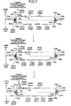
- the above intermittent transfer process is brought about when the paper money exists at the A point as shown in uppermost portion of fig. 7.
- the flapper 15b is directed for transferring the paper money toward the temporary storage 13 or the returnable paper money holder 14. Therefore, by repeating the cycle s22-s24 in the paper money handling apparatus 1, the paper money existing between the diverging point as the flapper 15b and the A position proceeds by small distance at each cycle so that the paper money is prevented from existing at the A point (as shown in middle and lowermost portions of fig. 7). Further, another paper money is prevented from being fed to the A point.
- the paper money is sometimes prevented from being removed from the A point irrespective of repeating the cycle s22-s24, and this process is finished when it is decided that the counted number of the counted reaches the predetermined number after repeating the cycle s22-s24. Therefore, the cycle s22-s24 is prevented from being continued everlastingly.
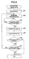
- the paper money handling apparatus 1 decides as to whether or not the paper money exists at the A point (s12). If it is decided at s12 that the paper money does not exist at the A point, the paper money handling apparatus 1 decided as to whether or not the paper money exists at the B point as the joint portion between the paper money transfer paths of the upper unit 2 and the lower unit 3b (s13). At s13, the paper money detecting sensor 24b decides as to whether or not the paper money is detected. The paper money existing at the B point extends between the upper unit 2 and the lower unit 3b. In other words, at s13, it is decided as to whether or not the paper money extends between the upper unit 2 and the lower unit 3b. If the paper money handling apparatus 1 decides at s13 that the paper money exists at the B point, the paper money handling apparatus 1 performs an intermittent transfer process B as shown in fig. 8 (s18).
- the paper money handling apparatus 1 performs an error treatment for indicating on the display operation part 34 a message of that the paper money exists at the A point to be known by the operator, when it is decided at s12 that the paper money is not removed from the A point (s16). Therefore, since the operator can recognize that the paper money exists at the joint portion between the upper unit 2 and the lower unit 3b before separating the upper unit 2 and the lower unit 3b from each other, the separating operation can be performed carefully.
- the intermittent transfer process B at s 14 is similar to the process shown in fig. 6, but is differentiated from the process shown in fig. 6 in that it is decided at s36 whether or not the paper money exists at the B point.
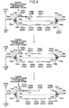
- the intermittent transfer process at s 14 is brought about when the paper money exists at the B point as shown in an uppermost portion of fig. 9.
- the flapper 15b is directed for transferring paper toward the temporary storage 13 or the returnable paper money holder 14.
- the paper money between the diverging point formed by the flapper 15b and the A point proceeds by small length at each cycle, so that the paper money is removed from the B point (make reference to middle and lowermost portions of fig. 9).
- the flapper 15b is directed for transferring paper toward the temporary storage 13 or the returnable paper money holder 14 when the intermittent transfer process is brought about at s14, the paper money is prevented from existing at the A point when the intermittent transfer process at s14 is finished.
- the paper money handling apparatus 1 brings about the intermittent transfer process at s14, and it is decided as to whether or not the paper money is removed from the B point (a15). If it is decided at s15 that the paper money is not removed from the B point, an error treatment in which the display operation part 34 shows a message of that the paper money exists at the B point to be known by the operator is performed (s17).
- the paper money handling apparatus 1 of the embodiment performs the process shown in fig. 3 when the clogging of the paper money occurs on the paper money transfer path, the paper money is prevented from extending between the upper unit 2 and the lower unit 3. Therefore, when the upper unit 2 and the lower unit 3 are separated from each other by the operator to treat the clogging of the paper money, the paper money is prevented from being broken and dropping out of the apparatus, so that a trouble in repair work for the clogging of the paper money in the bodies of the apparatus can be decreased. Further, since the bypass transfer path usually not used as the paper money transfer path as disclosed by the prior document is not needed, a structure of the bodies of the apparatus is simplified and an increase in cost thereof is prevented.
- a first unit including a paper money discriminator part for discriminating the paper money regarding its kind of denomination and a second unit including a paper money storage part for storing the paper money are separable from each other, and first and second paper money transfer paths of the first and second units are joined each other through a first joint portion through which the paper money is transferred from the first unit to the second unit when the first and second units are joined each other.
- Paper money transfer means transfers the paper money along the combined paper money transfer paths so that the paper money is transferred between the first and second units. Further, when jam detecting means detects an occurrence of clogging of the paper money, that is, jam on the paper money transfer path, the paper money transfer means stops the transfer of the paper money.
- the paper money transfer means repeats intermittently a transfer of the paper money until the paper money is prevented from being detected at two of the joint portions. An operation of transferring the paper money by, for example, some centimeter (2-3 cm) and stopping is repeated.
- the bodies of the apparatus can be stopped with preventing the paper money from existing at the joint portions between the units. Therefore, when the units are separated from each other and the operator removes the paper money from the paper money transfer path to remove the trouble of the clogging of the paper money, the paper money is prevented from being broken by tensile and dropping out of the apparatus. Further, since a bypass transfer path not used usually des not need to be arranged on the paper money transfer path, the structure of the bodies of the apparatus is prevented from being complicated.
- Forwarding course switching means for selectively switching a course to which the paper money is transferred is arranged along the first paper money transfer path on a diverging point at which a transfer path for transferring the paper money to the first joint portion and a transfer path for transferring the paper money to another portion in the first unit diverge from each other, and since the forwarding course switching means selects the transfer path for transferring the paper money to the another portion other than the first joint portion when the jam detecting means detects the clogging of the paper money on the paper money transfer path, the forwarding course switching means switches at the diverging point the course to which the paper money is transferred in such a manner that the paper money existing on the first paper money transfer path is transferred to the another portion other than the first joint portion when the clogging of the paper money occurs on the paper money transfer path. Therefore, when the transfer of the paper money is repeated intermittently, the money existing on the first paper money transfer path is prevented from being transferred in turn to the first joint portion so that a number of intermittent repeats of the transfer of the paper money is decreased.
- the forwarding course switching means selects the transfer path for transferring the paper money to the first joint portion when the jam detecting means detects the clogging of the paper money on the paper money transfer path
- the forwarding course switching means switches the course to which the paper money is transferred from the transfer path for transferring the paper money to the first joint portion to the transfer path for transferring the paper money to the another portion other than the first joint portion after the paper money detecting means does not detect the existence of the paper money at the upstream position distant from the diverging point by the predetermined distance in the transfer direction.
- the course to which the paper money is transferred is switched at the diverging point from the transfer path for transferring the paper money to the first joint portion to the transfer path for transferring the paper money to the another portion other than the first joint portion after the paper money detecting means does not detect the existence of the paper money at the upstream position distant from the diverging point by the predetermined distance in the transfer direction. Therefore, the course to which the paper money is transferred is switched at the diverging point when the paper money does not exists at the diverging point, so that another clogging of the paper money is prevented from occurring at the diverging point when switching.
- the predetermined distance is shorter than a distance by which the paper money proceeds within a time period needed for switching at the diverging point the course to which the paper money is transferred, for example, 10-20 ms.
- the paper money transfer means stops the intermittent transfer of the paper money in response to that the number of intermittent repeats of the transfer of the paper money reaches a predetermined number when the paper money detecting means detects the existence of the paper money at at least one of the vicinity of the first joint portion and the vicinity of the second joint portion.
- the intermittent repeats of the transfer of the paper money is prevented from being continued everlastingly when the clogging of the paper money occurs.
Landscapes
- Physics & Mathematics (AREA)
- General Physics & Mathematics (AREA)
- Controlling Sheets Or Webs (AREA)
- Separation, Sorting, Adjustment, Or Bending Of Sheets To Be Conveyed (AREA)
Abstract
Description
Claims (20)
- A sheet handling apparatus for handling a sheet therein, comprising,
a first body (2) including a first transfer path along which the sheet is driven to be moved,
a second body (3) including a second transfer path along which the sheet is driven to be moved,
an interface area (A point, B point) through which the first and second transfer paths of the first and second bodies movable with respect to each other on occasion demands, are capable of communicating with each other so that the sheet is capable of being transferred through the interface area between the first and second transfer paths when the first and second bodies have a predetermined positional relationship therebetween, and
a controller (31) for controlling at least one of the first and second transfer paths to drive the sheet to be moved along the at least one of the first and second transfer paths. - A sheet handling apparatus according to claim 1, further comprising a sheet existence sensor (24, 25) arranged to detect as to whether or not the sheet exists at the interface area, wherein the controller controls, in response to that the sheet existence sensor detects the existence of the sheet at the interface area and the controller receives a signal corresponding to a status other than the existence of the sheet at the interface area, the at least one of the first and second transfer paths to drive the sheet to be moved along the at least one of the first and second transfer paths until the sheet is removed from the interface area to prevent the existence of the sheet at the interface area from being detected by the sheet existence sensor.
- A sheet handling apparatus according to claim 2, wherein the status is a clogging of the sheet on at least one of the first transfer path, the second transfer path and the interface area.
- A sheet handling apparatus according to claim 2, wherein the status is at least one of probability and preliminary-notice of the relative movement between the first and second bodies.
- A sheet handling apparatus according to claim 2, wherein the status is at least one of probability and preliminary-notice of an operation stop of at least one of the first transfer path, the second transfer path, the sheet existence sensor and the controller.
- A sheet handling apparatus according to claim 5, wherein the operation of the at least one of the first transfer path, the second transfer path, the sheet existence sensor and the controller is allowed to be actually stopped, in response to that the sheet is removed from the interface area to prevent the existence of the sheet at the interface area from being detected by the sheet existence sensor.
- A sheet handling apparatus according to any one of claims 2-6, wherein the controller controls, in response to that the sheet existence sensor detects the existence of the sheet at the interface area and the controller receives the signal, the at least one of the first and second transfer paths to drive the sheet in such a manner that a velocity of the sheet along the at least one of the first and second transfer paths is increased and decreased frequently.
- A sheet handling apparatus according to claim 7, wherein the controller controls, in response to that the sheet existence sensor detects the existence of the sheet at the interface area and the controller receives the signal, the at least one of the first and second transfer paths to drive the sheet in such a manner that the sheet is moved intermittently along the at least one of the first and second transfer paths.
- A sheet handling apparatus according to any one of claims 2-8, wherein the controller controls, in response to that the sheet existence sensor detects the existence of the sheet at the interface area and the controller receives the signal, the at least one of the first and second transfer paths to prevent the sheet from being moved along the at least one of the first and second transfer paths and subsequently to drive the sheet to be moved along the at least one of the first and second transfer paths.
- A sheet handling apparatus according to any one of claim 2-9, wherein the controller controls, in response to that the sheet existence sensor detects the existence of the sheet at the interface area and the controller receives the signal, the at least one of the first and second transfer paths to drive the sheet to be moved at a first velocity along the at least one of the first and second transfer paths and subsequently to drive the sheet to be moved at a second velocity higher than the first velocity along the at least one of the first and second transfer paths.
- A sheet handling apparatus according to any one of claims 2-10, wherein irrespective of whether or not the sheet is removed from the interface area, the controller prevents the at least one of the first and second transfer paths from driving the sheet to be moved along the at least one of the first and second transfer paths when at least one of a number of times of changes in velocity of the sheet along the at least one of the first and second transfer paths after the sheet existence sensor detects the existence of the sheet at the interface area and the controller receives the signal, a time period during which the sheet is moved after the sheet existence sensor detects the existence of the sheet at the interface area and the controller receives the signal, and a distance in which the sheet is moved after the sheet existence sensor detects the existence of the sheet at the interface area and the controller receives the signal, reaches a predetermined value.
- A sheet handling apparatus according to any one of claims 2-11, further comprising another interface area (B point) through which the first and second transfer paths of the first and second bodies movable with respect to each other on occasion demands, are capable of communicating with each other so that the sheet is capable of being transferred through the another interface area between the first and second transfer paths when the first and second bodies have the predetermined positional relationship therebetween, and another sheet existence sensor (24b, 25b) arranged to detect as to whether or not the sheet exists at the another interface area, wherein the controller controls, in response to that at least one of the sheet existence sensor and the another sheet existence sensor detects the existence of the sheet at at least one of the interface area and the another interface area and the controller receives the signal, the at least one of the first and second transfer paths to drive the sheet to be moved along the at least one of the first and second transfer paths until the sheet is removed from each of the interface area and the another interface area to prevent the existence of the sheet at each of the interface area and the another interface area from being detected by corresponding one of the sheet existence sensor and the another sheet existence sensor.
- A sheet handling apparatus according to any one of claims 1-12, wherein at least one of the first and second transfer paths has a main passage which is capable of receiving the sheet therein to be guided toward the interface area, an escape passage which is capable of receiving the sheet therein to prevent the sheet from being transferred toward the interface area, and a switch member (15b) movable with respect to the main passage and the escape passage between a first position for introducing the sheet into the main passage and a second position for introducing the sheet to the escape passage, and the switch member is positioned at the second position in response to that the controller receives a signal corresponding to a status of at least one of a clogging of the sheet on at least one of the first transfer path, the second transfer path and the interface area, at least one of probability and preliminary-notice of the relative movement between the first and second bodies, and at least one of probability and preliminary-notice of an operation stop of at least one of the first transfer path, the second transfer path, the sheet existence sensor and the controller.
- A sheet handling apparatus according to claim 13, further comprising a sheet existence sensor (16) arranged to detect an existence of the sheet at a detecting position distant from the switch member at an upstream side with respect to the switch member in a traveling direction of the sheet along the at least one of the first and second transfer paths, wherein the switch member is prevented from being moved between the first and second positions when the sheet existence sensor detects the existence of the sheet, and the switch member is allowed to be moved between the first and second positions when the sheet existence sensor detects nonexistence of the sheet.
- A sheet handling apparatus according to any one of claims 1-14, further comprising a sheet existence sensor (24, 25) arranged to detect as to whether or not the sheet exists at the interface area, wherein the controller outputs, in response to that the sheet existence sensor detects the existence of the sheet at the interface area and the controller receives a signal corresponding to a status other than the existence of the sheet at the interface area, an alert signal.
- A sheet handling apparatus according to claim 15, wherein the status includes at least one of a clogging of the sheet on at least one of the first transfer path, the second transfer path and the interface area, at least one of probability and preliminary-notice of the relative movement between the first and second bodies, and at least one of probability and preliminary-notice of an operation stop of at least one of the first transfer path, the second transfer path, the sheet existence sensor and the controller.
- A sheet handling apparatus according to any one of claims 2-16, wherein the sheet existence sensor detects the existence of the sheet at a single position of the interface area.
- A sheet handling apparatus according to any one of claims 2-16, wherein the sheet existence sensor detects the existence of the sheet at two positions of the interface area distant from each other in a traveling direction of the sheet along the at least one of the first and second transfer paths, so that nonexistence of the sheet at the interface area is detected when nonexistence of the sheet is detected at both of the two positions.
- A sheet handling apparatus according to any one of claims 1-18, wherein one of the first and second bodies includes a discriminator (11) for discriminating a kind of the sheet, and the other one of the first and second bodies includes a storage (21, 22) for storing the sheet.
- A sheet handling apparatus according to any one of claims 1-19, wherein the sheet is a paper money.
Applications Claiming Priority (2)
| Application Number | Priority Date | Filing Date | Title |
|---|---|---|---|
| JP2004057541 | 2004-03-02 | ||
| JP2004057541A JP4346474B2 (en) | 2004-03-02 | 2004-03-02 | Banknote handling equipment |
Publications (2)
| Publication Number | Publication Date |
|---|---|
| EP1571603A1 true EP1571603A1 (en) | 2005-09-07 |
| EP1571603B1 EP1571603B1 (en) | 2014-05-07 |
Family
ID=34747622
Family Applications (1)
| Application Number | Title | Priority Date | Filing Date |
|---|---|---|---|
| EP05004380.1A Expired - Lifetime EP1571603B1 (en) | 2004-03-02 | 2005-02-28 | Sheet handling machine |
Country Status (5)
| Country | Link |
|---|---|
| US (2) | US20050202771A1 (en) |
| EP (1) | EP1571603B1 (en) |
| JP (1) | JP4346474B2 (en) |
| CN (1) | CN100528718C (en) |
| TW (1) | TWI290122B (en) |
Cited By (4)
| Publication number | Priority date | Publication date | Assignee | Title |
|---|---|---|---|---|
| DE102007028858A1 (en) * | 2007-06-22 | 2009-01-02 | Wincor Nixdorf International Gmbh | Value ticket machine |
| EP1921585A3 (en) * | 2006-11-09 | 2009-03-04 | Hitachi-Omron Terminal Solutions, Corp. | Paper currency handling apparatus |
| WO2009083138A1 (en) * | 2007-12-21 | 2009-07-09 | Giesecke & Devrient Gmbh | Device for accepting and outputting banknotes |
| EP2058773A3 (en) * | 2007-11-07 | 2009-11-04 | Hitachi-Omron Terminal Solutions, Corp. | Sheet handling device |
Families Citing this family (20)
| Publication number | Priority date | Publication date | Assignee | Title |
|---|---|---|---|---|
| ITTO20060093A1 (en) * | 2006-02-10 | 2007-08-11 | Cts Cashpro Spa | EQUIPMENT FOR STORAGE BANKNOTES AND / OR CARDS AND THE LIKE |
| JP4199790B2 (en) * | 2006-09-01 | 2008-12-17 | シャープ株式会社 | Image processing device |
| CN103955991A (en) * | 2008-01-17 | 2014-07-30 | 光荣株式会社 | Paper money processing device |
| US8276901B2 (en) * | 2008-03-26 | 2012-10-02 | Glory Ltd. | Paper sheet handling apparatus and paper sheet handling method |
| DE102008021517A1 (en) * | 2008-04-30 | 2009-11-05 | Giesecke & Devrient Gmbh | Device for processing banknotes |
| JP5241610B2 (en) * | 2009-05-26 | 2013-07-17 | 日立オムロンターミナルソリューションズ株式会社 | Banknote transaction equipment |
| JP5463748B2 (en) * | 2009-06-16 | 2014-04-09 | 沖電気工業株式会社 | Media processing device |
| JP5384278B2 (en) * | 2009-10-05 | 2014-01-08 | 日立オムロンターミナルソリューションズ株式会社 | Banknote handling equipment |
| JP5387514B2 (en) * | 2010-06-11 | 2014-01-15 | 沖電気工業株式会社 | Banknote handling equipment |
| JP2012008926A (en) * | 2010-06-28 | 2012-01-12 | Oki Electric Ind Co Ltd | Automatic transaction device |
| JP5500267B2 (en) * | 2010-12-01 | 2014-05-21 | 沖電気工業株式会社 | Automatic transaction equipment |
| KR101272388B1 (en) * | 2011-01-05 | 2013-06-07 | 주식회사 엘지씨엔에스 | Automated teller machine |
| JP5602674B2 (en) * | 2011-05-16 | 2014-10-08 | 日立オムロンターミナルソリューションズ株式会社 | Paper sheet processing apparatus and identification algorithm update program |
| JP5814085B2 (en) * | 2011-11-14 | 2015-11-17 | 日立オムロンターミナルソリューションズ株式会社 | Banknote handling equipment |
| JP5834865B2 (en) * | 2011-12-13 | 2015-12-24 | 沖電気工業株式会社 | Banknote depositing and dispensing machine and banknote processing apparatus |
| US9734648B2 (en) * | 2012-12-11 | 2017-08-15 | Ncr Corporation | Method of categorising defects in a media item |
| WO2014192128A1 (en) * | 2013-05-31 | 2014-12-04 | 日立オムロンターミナルソリューションズ株式会社 | Paper sheet handling device and paper sheet handling mechanism |
| JP6503664B2 (en) * | 2014-09-11 | 2019-04-24 | 沖電気工業株式会社 | Medium processing apparatus and medium transaction apparatus |
| CN104732650B (en) * | 2015-03-27 | 2017-06-16 | 深圳怡化电脑股份有限公司 | The processing method and system of a kind of bank note |
| CN113256911A (en) * | 2020-12-31 | 2021-08-13 | 深圳怡化电脑股份有限公司 | Cash card processing method and system, money depositing and withdrawing equipment and storage medium |
Citations (5)
| Publication number | Priority date | Publication date | Assignee | Title |
|---|---|---|---|---|
| JPS5421725A (en) * | 1977-07-19 | 1979-02-19 | Ricoh Co Ltd | Treating method for sheet jamming |
| US5024431A (en) * | 1987-10-16 | 1991-06-18 | Minolta Camera Kabushiki Kaisha | Sheet transport device with easy sheet jam handling |
| US5678123A (en) * | 1995-08-14 | 1997-10-14 | Samsung Electronics Co., Ltd. | Apparatus and method for eliminating paper jam in image forming device |
| US20020092727A1 (en) * | 2000-12-25 | 2002-07-18 | Riichi Kato | Bill receiving/dispensing machine |
| US20030156298A1 (en) * | 2002-02-15 | 2003-08-21 | Kazuhiro Matsuyama | Image forming apparatus |
Family Cites Families (28)
| Publication number | Priority date | Publication date | Assignee | Title |
|---|---|---|---|---|
| US3193283A (en) * | 1962-12-28 | 1965-07-06 | Sperry Rand Corp | Document sorting |
| US3870868A (en) * | 1972-07-21 | 1975-03-11 | Pennsylvania Res Ass Inc | Control mechanisms for document-handling apparatus |
| US4132401A (en) * | 1977-05-27 | 1979-01-02 | Xerox Corporation | Copier document sensing and control system |
| JPS61276090A (en) * | 1985-05-31 | 1986-12-06 | 株式会社東芝 | Circulation type teller's equipment |
| JPS61276089A (en) * | 1985-05-31 | 1986-12-06 | 株式会社東芝 | Paper money transport controller |
| JPS6395595A (en) * | 1986-10-13 | 1988-04-26 | 沖電気工業株式会社 | Paper money teller apparatus |
| JPS63159994A (en) * | 1986-12-24 | 1988-07-02 | ロ−レルバンクマシン株式会社 | Paper money teller machine |
| US5662320A (en) * | 1992-10-12 | 1997-09-02 | Fujitsu Limited | Apparatus having document transport mechanism |
| JP3118099B2 (en) * | 1992-12-03 | 2000-12-18 | 株式会社日本コンラックス | Banknote handling equipment |
| GB9418844D0 (en) * | 1994-09-19 | 1994-11-09 | At & T Global Inf Solution | Document processing apparatus |
| JPH0991494A (en) | 1995-09-26 | 1997-04-04 | Hitachi Ltd | Banknote deposit and withdrawal machine |
| US6520308B1 (en) * | 1996-06-28 | 2003-02-18 | Coinstar, Inc. | Coin discrimination apparatus and method |
| JP3499411B2 (en) * | 1996-09-18 | 2004-02-23 | ローレルバンクマシン株式会社 | Banknote depositing / dispensing machine |
| US5924686A (en) * | 1996-10-25 | 1999-07-20 | Pitney Bowes Inc. | Method for controlling the velocity of sheet separation |
| GB9623046D0 (en) * | 1996-11-06 | 1997-01-08 | Ncr Int Inc | Escrow storage device |
| EP1378869B1 (en) * | 1997-10-06 | 2014-08-06 | Hitachi-Omron Terminal Solutions, Corp. | Leaflets handling apparatus |
| US6039164A (en) * | 1998-04-13 | 2000-03-21 | Agent Systems, Inc. | Automatic validating farebox system and method |
| JP2000200379A (en) * | 1999-01-07 | 2000-07-18 | Fujitsu Ltd | Paper processing equipment |
| JP3631928B2 (en) * | 1999-09-30 | 2005-03-23 | 富士通株式会社 | Paper sheet feeding unit and paper sheet handling apparatus |
| JP3815651B2 (en) * | 1999-10-19 | 2006-08-30 | 日立オムロンターミナルソリューションズ株式会社 | Banknote deposit and withdrawal machine |
| EP1130551A3 (en) * | 2000-02-22 | 2004-01-21 | Glory Kogyo Kabushiki Kaisha | Bill handling machine |
| AU2001271065A1 (en) * | 2000-07-17 | 2002-01-30 | Japan Cash Machine Co., Ltd. | Bill processing device |
| JP3959706B2 (en) * | 2001-03-01 | 2007-08-15 | 日立オムロンターミナルソリューションズ株式会社 | Banknote handling equipment |
| US6557849B2 (en) * | 2001-06-21 | 2003-05-06 | Da La Rue International | Sheet handling apparatus |
| JP4012423B2 (en) * | 2002-03-26 | 2007-11-21 | 日立オムロンターミナルソリューションズ株式会社 | Banknote handling equipment |
| US7156391B2 (en) * | 2002-05-15 | 2007-01-02 | Canon Kabushiki Kaisha | Driving apparatus, sheet processing apparatus having driving apparatus, image forming apparatus having sheet processing apparatus and control system |
| JP2004224481A (en) * | 2003-01-21 | 2004-08-12 | Toshiba Corp | Paper processing equipment |
| JP2004310653A (en) * | 2003-04-10 | 2004-11-04 | Hitachi Ltd | Automatic teller machine and its operation method |
-
2004
- 2004-03-02 JP JP2004057541A patent/JP4346474B2/en not_active Expired - Fee Related
-
2005
- 2005-02-24 TW TW094105609A patent/TWI290122B/en not_active IP Right Cessation
- 2005-02-28 EP EP05004380.1A patent/EP1571603B1/en not_active Expired - Lifetime
- 2005-02-28 CN CNB2005100511309A patent/CN100528718C/en not_active Expired - Fee Related
- 2005-03-01 US US11/067,924 patent/US20050202771A1/en not_active Abandoned
-
2008
- 2008-02-19 US US12/071,202 patent/US7455293B2/en not_active Expired - Fee Related
Patent Citations (5)
| Publication number | Priority date | Publication date | Assignee | Title |
|---|---|---|---|---|
| JPS5421725A (en) * | 1977-07-19 | 1979-02-19 | Ricoh Co Ltd | Treating method for sheet jamming |
| US5024431A (en) * | 1987-10-16 | 1991-06-18 | Minolta Camera Kabushiki Kaisha | Sheet transport device with easy sheet jam handling |
| US5678123A (en) * | 1995-08-14 | 1997-10-14 | Samsung Electronics Co., Ltd. | Apparatus and method for eliminating paper jam in image forming device |
| US20020092727A1 (en) * | 2000-12-25 | 2002-07-18 | Riichi Kato | Bill receiving/dispensing machine |
| US20030156298A1 (en) * | 2002-02-15 | 2003-08-21 | Kazuhiro Matsuyama | Image forming apparatus |
Non-Patent Citations (1)
| Title |
|---|
| PATENT ABSTRACTS OF JAPAN vol. 003, no. 041 (E - 103) 10 April 1979 (1979-04-10) * |
Cited By (7)
| Publication number | Priority date | Publication date | Assignee | Title |
|---|---|---|---|---|
| EP1921585A3 (en) * | 2006-11-09 | 2009-03-04 | Hitachi-Omron Terminal Solutions, Corp. | Paper currency handling apparatus |
| US7780076B2 (en) | 2006-11-09 | 2010-08-24 | Hitachi-Omron Terminal Solutions, Corp. | Paper currency handling apparatus |
| DE102007028858A1 (en) * | 2007-06-22 | 2009-01-02 | Wincor Nixdorf International Gmbh | Value ticket machine |
| US8985297B2 (en) | 2007-06-22 | 2015-03-24 | Wincor Nixdorf International Gmbh | Voucher machine |
| EP2058773A3 (en) * | 2007-11-07 | 2009-11-04 | Hitachi-Omron Terminal Solutions, Corp. | Sheet handling device |
| US8246046B2 (en) | 2007-11-07 | 2012-08-21 | Hitachi-Omron Terminal Solutions, Corp. | Sheet handling device |
| WO2009083138A1 (en) * | 2007-12-21 | 2009-07-09 | Giesecke & Devrient Gmbh | Device for accepting and outputting banknotes |
Also Published As
| Publication number | Publication date |
|---|---|
| TWI290122B (en) | 2007-11-21 |
| CN100528718C (en) | 2009-08-19 |
| TW200533584A (en) | 2005-10-16 |
| US20080150224A1 (en) | 2008-06-26 |
| JP4346474B2 (en) | 2009-10-21 |
| EP1571603B1 (en) | 2014-05-07 |
| US7455293B2 (en) | 2008-11-25 |
| US20050202771A1 (en) | 2005-09-15 |
| JP2005250642A (en) | 2005-09-15 |
| CN1663895A (en) | 2005-09-07 |
Similar Documents
| Publication | Publication Date | Title |
|---|---|---|
| US7455293B2 (en) | Sheet handling machine | |
| US8630475B2 (en) | Banknote handling machine and banknote handling method | |
| CA2707331A1 (en) | Banknote handling machine and banknote handling method | |
| WO2014044037A1 (en) | Financial self-service device, and laminated dielectric transmission system and method thereof | |
| EP3188140B1 (en) | Medium processing apparatus | |
| JP5058049B2 (en) | Paper sheet transport device and banknote handling machine | |
| RU2581777C1 (en) | Device for handling banknotes | |
| KR101041205B1 (en) | Conveying direction switching device and paper sheet conveying device | |
| KR20200037685A (en) | Apparatus for bill receiving and dispensing | |
| US10984624B2 (en) | Paper sheet handling apparatus and paper sheet handling method | |
| JP3212673B2 (en) | Banknote jam recovery method and recovery device | |
| EP4102476A1 (en) | Medium handling method and medium handling device | |
| CN111275882B (en) | Cash processing apparatus and control method thereof | |
| JP5144208B2 (en) | Packaging coin deposit machine and packaging coin deposit system | |
| JP4210796B2 (en) | Banknote storage state notification method and program for banknote identification machine | |
| JP2624923B2 (en) | Bill counting processor | |
| JP6750130B2 (en) | Paper processing equipment | |
| KR102875366B1 (en) | Teller cash recycler and control method thereof | |
| JP2017045171A (en) | Medium arrangement device | |
| KR102312676B1 (en) | Paper money counting module and control method thereof | |
| JP7793197B2 (en) | Banknote validator | |
| JP3594352B2 (en) | Paper handling equipment | |
| JP4489735B2 (en) | Paper loading device | |
| JPH10291726A (en) | Image forming device | |
| JPH1159969A (en) | Medium conveying device and jamming determining method |
Legal Events
| Date | Code | Title | Description |
|---|---|---|---|
| PUAI | Public reference made under article 153(3) epc to a published international application that has entered the european phase |
Free format text: ORIGINAL CODE: 0009012 |
|
| AK | Designated contracting states |
Kind code of ref document: A1 Designated state(s): AT BE BG CH CY CZ DE DK EE ES FI FR GB GR HU IE IS IT LI LT LU MC NL PL PT RO SE SI SK TR |
|
| AX | Request for extension of the european patent |
Extension state: AL BA HR LV MK YU |
|
| 17P | Request for examination filed |
Effective date: 20060227 |
|
| AKX | Designation fees paid |
Designated state(s): CH DE LI |
|
| 17Q | First examination report despatched |
Effective date: 20060720 |
|
| GRAP | Despatch of communication of intention to grant a patent |
Free format text: ORIGINAL CODE: EPIDOSNIGR1 |
|
| INTG | Intention to grant announced |
Effective date: 20131119 |
|
| RIN1 | Information on inventor provided before grant (corrected) |
Inventor name: HATA, HIDETOSHI Inventor name: HAMADA, KOICHI Inventor name: SHIMIZU, YASUHIRO Inventor name: NAKAMURA, TAKESHI |
|
| GRAS | Grant fee paid |
Free format text: ORIGINAL CODE: EPIDOSNIGR3 |
|
| GRAA | (expected) grant |
Free format text: ORIGINAL CODE: 0009210 |
|
| AK | Designated contracting states |
Kind code of ref document: B1 Designated state(s): CH DE LI |
|
| REG | Reference to a national code |
Ref country code: DE Ref legal event code: R096 Ref document number: 602005043508 Country of ref document: DE Effective date: 20140612 |
|
| REG | Reference to a national code |
Ref country code: DE Ref legal event code: R097 Ref document number: 602005043508 Country of ref document: DE |
|
| PLBE | No opposition filed within time limit |
Free format text: ORIGINAL CODE: 0009261 |
|
| STAA | Information on the status of an ep patent application or granted ep patent |
Free format text: STATUS: NO OPPOSITION FILED WITHIN TIME LIMIT |
|
| 26N | No opposition filed |
Effective date: 20150210 |
|
| REG | Reference to a national code |
Ref country code: DE Ref legal event code: R097 Ref document number: 602005043508 Country of ref document: DE Effective date: 20150210 |
|
| REG | Reference to a national code |
Ref country code: CH Ref legal event code: PL |
|
| PG25 | Lapsed in a contracting state [announced via postgrant information from national office to epo] |
Ref country code: LI Free format text: LAPSE BECAUSE OF NON-PAYMENT OF DUE FEES Effective date: 20150228 Ref country code: CH Free format text: LAPSE BECAUSE OF NON-PAYMENT OF DUE FEES Effective date: 20150228 |
|
| PGFP | Annual fee paid to national office [announced via postgrant information from national office to epo] |
Ref country code: DE Payment date: 20160223 Year of fee payment: 12 |
|
| REG | Reference to a national code |
Ref country code: DE Ref legal event code: R119 Ref document number: 602005043508 Country of ref document: DE |
|
| PG25 | Lapsed in a contracting state [announced via postgrant information from national office to epo] |
Ref country code: DE Free format text: LAPSE BECAUSE OF NON-PAYMENT OF DUE FEES Effective date: 20170901 |