EP1571312A2 - Klappenlagerbefestigung - Google Patents
Klappenlagerbefestigung Download PDFInfo
- Publication number
- EP1571312A2 EP1571312A2 EP05000301A EP05000301A EP1571312A2 EP 1571312 A2 EP1571312 A2 EP 1571312A2 EP 05000301 A EP05000301 A EP 05000301A EP 05000301 A EP05000301 A EP 05000301A EP 1571312 A2 EP1571312 A2 EP 1571312A2
- Authority
- EP
- European Patent Office
- Prior art keywords
- flap
- housing
- bearing
- air intake
- intake duct
- Prior art date
- Legal status (The legal status is an assumption and is not a legal conclusion. Google has not performed a legal analysis and makes no representation as to the accuracy of the status listed.)
- Withdrawn
Links
- 238000004512 die casting Methods 0.000 claims description 3
- 238000002485 combustion reaction Methods 0.000 claims description 2
- 239000004033 plastic Substances 0.000 claims description 2
- 230000001105 regulatory effect Effects 0.000 abstract 1
- 238000007373 indentation Methods 0.000 description 4
- 238000004519 manufacturing process Methods 0.000 description 4
- 239000000463 material Substances 0.000 description 3
- 238000003780 insertion Methods 0.000 description 2
- 230000037431 insertion Effects 0.000 description 2
- 239000002991 molded plastic Substances 0.000 description 2
- FYYHWMGAXLPEAU-UHFFFAOYSA-N Magnesium Chemical compound [Mg] FYYHWMGAXLPEAU-UHFFFAOYSA-N 0.000 description 1
- 230000009969 flowable effect Effects 0.000 description 1
- 238000001746 injection moulding Methods 0.000 description 1
- 229910052749 magnesium Inorganic materials 0.000 description 1
- 239000011777 magnesium Substances 0.000 description 1
- 230000007257 malfunction Effects 0.000 description 1
- 238000002844 melting Methods 0.000 description 1
- 230000008018 melting Effects 0.000 description 1
- 238000000034 method Methods 0.000 description 1
- 238000003860 storage Methods 0.000 description 1
Images

Classifications
-
- F—MECHANICAL ENGINEERING; LIGHTING; HEATING; WEAPONS; BLASTING
- F02—COMBUSTION ENGINES; HOT-GAS OR COMBUSTION-PRODUCT ENGINE PLANTS
- F02B—INTERNAL-COMBUSTION PISTON ENGINES; COMBUSTION ENGINES IN GENERAL
- F02B31/00—Modifying induction systems for imparting a rotation to the charge in the cylinder
- F02B31/04—Modifying induction systems for imparting a rotation to the charge in the cylinder by means within the induction channel, e.g. deflectors
- F02B31/06—Movable means, e.g. butterfly valves
-
- F—MECHANICAL ENGINEERING; LIGHTING; HEATING; WEAPONS; BLASTING
- F02—COMBUSTION ENGINES; HOT-GAS OR COMBUSTION-PRODUCT ENGINE PLANTS
- F02B—INTERNAL-COMBUSTION PISTON ENGINES; COMBUSTION ENGINES IN GENERAL
- F02B27/00—Use of kinetic or wave energy of charge in induction systems, or of combustion residues in exhaust systems, for improving quantity of charge or for increasing removal of combustion residues
- F02B27/02—Use of kinetic or wave energy of charge in induction systems, or of combustion residues in exhaust systems, for improving quantity of charge or for increasing removal of combustion residues the systems having variable, i.e. adjustable, cross-sectional areas, chambers of variable volume, or like variable means
-
- F—MECHANICAL ENGINEERING; LIGHTING; HEATING; WEAPONS; BLASTING
- F02—COMBUSTION ENGINES; HOT-GAS OR COMBUSTION-PRODUCT ENGINE PLANTS
- F02B—INTERNAL-COMBUSTION PISTON ENGINES; COMBUSTION ENGINES IN GENERAL
- F02B27/00—Use of kinetic or wave energy of charge in induction systems, or of combustion residues in exhaust systems, for improving quantity of charge or for increasing removal of combustion residues
- F02B27/02—Use of kinetic or wave energy of charge in induction systems, or of combustion residues in exhaust systems, for improving quantity of charge or for increasing removal of combustion residues the systems having variable, i.e. adjustable, cross-sectional areas, chambers of variable volume, or like variable means
- F02B27/0205—Use of kinetic or wave energy of charge in induction systems, or of combustion residues in exhaust systems, for improving quantity of charge or for increasing removal of combustion residues the systems having variable, i.e. adjustable, cross-sectional areas, chambers of variable volume, or like variable means characterised by the charging effect
- F02B27/0215—Oscillating pipe charging, i.e. variable intake pipe length charging
-
- F—MECHANICAL ENGINEERING; LIGHTING; HEATING; WEAPONS; BLASTING
- F02—COMBUSTION ENGINES; HOT-GAS OR COMBUSTION-PRODUCT ENGINE PLANTS
- F02B—INTERNAL-COMBUSTION PISTON ENGINES; COMBUSTION ENGINES IN GENERAL
- F02B27/00—Use of kinetic or wave energy of charge in induction systems, or of combustion residues in exhaust systems, for improving quantity of charge or for increasing removal of combustion residues
- F02B27/02—Use of kinetic or wave energy of charge in induction systems, or of combustion residues in exhaust systems, for improving quantity of charge or for increasing removal of combustion residues the systems having variable, i.e. adjustable, cross-sectional areas, chambers of variable volume, or like variable means
- F02B27/0226—Use of kinetic or wave energy of charge in induction systems, or of combustion residues in exhaust systems, for improving quantity of charge or for increasing removal of combustion residues the systems having variable, i.e. adjustable, cross-sectional areas, chambers of variable volume, or like variable means characterised by the means generating the charging effect
- F02B27/0268—Valves
- F02B27/0273—Flap valves
-
- F—MECHANICAL ENGINEERING; LIGHTING; HEATING; WEAPONS; BLASTING
- F02—COMBUSTION ENGINES; HOT-GAS OR COMBUSTION-PRODUCT ENGINE PLANTS
- F02D—CONTROLLING COMBUSTION ENGINES
- F02D9/00—Controlling engines by throttling air or fuel-and-air induction conduits or exhaust conduits
- F02D9/08—Throttle valves specially adapted therefor; Arrangements of such valves in conduits
- F02D9/10—Throttle valves specially adapted therefor; Arrangements of such valves in conduits having pivotally-mounted flaps
- F02D9/1035—Details of the valve housing
- F02D9/106—Sealing of the valve shaft in the housing, e.g. details of the bearings
-
- F—MECHANICAL ENGINEERING; LIGHTING; HEATING; WEAPONS; BLASTING
- F02—COMBUSTION ENGINES; HOT-GAS OR COMBUSTION-PRODUCT ENGINE PLANTS
- F02D—CONTROLLING COMBUSTION ENGINES
- F02D9/00—Controlling engines by throttling air or fuel-and-air induction conduits or exhaust conduits
- F02D9/08—Throttle valves specially adapted therefor; Arrangements of such valves in conduits
- F02D9/10—Throttle valves specially adapted therefor; Arrangements of such valves in conduits having pivotally-mounted flaps
- F02D9/109—Throttle valves specially adapted therefor; Arrangements of such valves in conduits having pivotally-mounted flaps having two or more flaps
- F02D9/1095—Rotating on a common axis, e.g. having a common shaft
-
- Y—GENERAL TAGGING OF NEW TECHNOLOGICAL DEVELOPMENTS; GENERAL TAGGING OF CROSS-SECTIONAL TECHNOLOGIES SPANNING OVER SEVERAL SECTIONS OF THE IPC; TECHNICAL SUBJECTS COVERED BY FORMER USPC CROSS-REFERENCE ART COLLECTIONS [XRACs] AND DIGESTS
- Y02—TECHNOLOGIES OR APPLICATIONS FOR MITIGATION OR ADAPTATION AGAINST CLIMATE CHANGE
- Y02T—CLIMATE CHANGE MITIGATION TECHNOLOGIES RELATED TO TRANSPORTATION
- Y02T10/00—Road transport of goods or passengers
- Y02T10/10—Internal combustion engine [ICE] based vehicles
- Y02T10/12—Improving ICE efficiencies
Definitions
- the invention relates to a Klappenlagerbefest Trent on an air intake duct system an internal combustion engine, wherein the air intake duct system at least one-piece housing, in which a flap device arranged which is a flap shaft on which at least one flap body is arranged and at least one bearing element, in which the flap shaft is mounted, has, wherein the flap device via the at least one bearing element in the housing the air intake duct system is attached.
- flaps can be in known Way as switching flaps for switching the effective Saugkanalrohrauer or serve as tumble flaps or swirl flaps for generating a vortex in the cylinder.
- an air intake duct system with a switching device flap described which also consists of an insert frame and a it is rotatably mounted shift shaft.
- This is a one-piece Bearing frame that receives two shifter shafts for a V-engine. Again, the entire shelf frame in corresponding recesses of the Housing the air intake duct system used and by the assembly the two housing parts fixed in the air intake duct system.
- DE 102 36 393 discloses a tumble flap device for an air intake duct system discloses wherein each flap associated with a single bearing element is, in which the Tumbleklappe is pivotable. Also these bearing elements initially with the flaps form fit in a first housing part the air intake duct system inserted and by screwing the second housing part fixed.
- a flap device to create in an air intake duct system, which also at positions in the Can take place air intake duct system, where a positive fixation through the housing parts of the air intake duct system is not possible without additional To use fasteners. It should also be an exact position fixation the bearing elements are achieved in the housing, without adhering to tight tolerances need to be, so that inexpensive injection-molded plastic shafts can be used. Compared to fasteners with screws or the like should be achieved a higher safety and life.
- the at least one bearing element Having projections which in the assembled state by corresponding Openings in the housing of Lucasansaugkanalsystems rich, through Hot deformation of the projections, the at least one bearing element on the housing is attached.
- Such a design is a cost effective way an exact Fixation on the housing of the air intake duct system achieved without additional To use fasteners, causing damage to the engine by solving Parts are avoided.
- the bearing elements in relation to their dimensions a higher tolerance range compared to the known positive locking Have connections.
- the housing around the openings, through which the projections of the at least one bearing element rich indentations on, so that after the hot deformation of the projections, the surface of the Housing is essentially smooth. This ensures that the attachment of the Bearing elements also take place at a position in the housing of the suction tube can, on which the projections are arranged in the region of the air-conducting channels, without obtaining flow losses through the protrusions after assembly.
- each individual bearing element which is attached to the housing via the projections, at least two projections.
- Corresponding each bearing element receives at least two fixing points, causing a twisting the bearing element within the Beeransaugkanalsystems reliably prevented becomes.
- the projections are circular pins and the openings formed as bores, whereby a simple manufacturability both the housing part of the suction tube and the projections on the bearing elements is reached.
- the housing of the air intake duct system is made of die-cast, in particular Magnesium die-casting, and the flap device made of plastic. Due to the different melting points of the materials is the hot deformation to attach the bearing elements thus easy to perform and the entire flap device is inexpensive, for example by injection molding produced.
- the housing of the air intake duct system designed in several parts, the flap device to an upper insert of the housing is attached.
- the flap device to an upper insert of the housing is attached.
- the flap device is in or on arranged multi-part bearing frame, in which the flap shaft with the at least a flap body is mounted, wherein the flap device pre-assembled in the Housing the air intake duct system can be inserted. In this way, the flap device be introduced into the housing in only one process step, because there is a complete self-contained unit.
- the flap device for each flap body at least one bearing element, which executed one or more parts is.
- the shape of the corresponding housing part can be simplified and yet a secure fit and a good attachment of the entire flap device in the Housing be guaranteed.
- the flap device at least a bearing element, which is made of several parts, wherein one or more first bearing parts, which completely or partially enclose the valve shaft, with a shaped wall surface against correspondingly shaped wall surfaces of the housing abut the Heilansaugkanalsystems and one or more second bearing parts, which have the projections, so rest on the or the first bearing parts, that by the hot deformation of the projections, which through the openings rich in the housing that or the first bearing parts are positively secured.
- the assembly is directly in the corresponding housing part the air intake duct system instead.
- the same bearing elements can be used for different sized but substantially identical Gutansaugkanalsysteme be used so that tooling and manufacturing costs due to the large quantities are reduced.
- two flap shafts are on or off multi-part bearing frame mounted in the housing, so that, for example, in a V-engine in just one assembly step, the two cylinder banks associated flap devices can be attached.
- a Klappenlagerbefest Trent is created, which is suitable for all forms of Air intake duct systems can be used, with additional cost-effective Valve shaft shafts for which separate bearings are necessary used can be used without having to use additional fasteners. malfunction for example, by loosening a screw can be reliably avoided and increases the life of the entire flap device accordingly. The simple assembly and production of further costs are saved.
- FIG. 1 shows a first embodiment of an air intake duct system 1 with a flapper mounting according to the invention.
- the air intake duct system 1 consists of a multi-part housing 2, in which case the upper housing part 3 and the upper insert 4 are shown.
- the flap bearing attachment takes place at the top Insert 4, wherein a flap device 5 as a switching flap device for Changing the effective vibration tube length is used.
- the flap device 5 consists of two switching valve shafts 6, 7 on which Switching flap body 8 are arranged, which via an adjusting device, not shown in a short-circuit path 9 freely switching or closing position can be turned. These flap body 8 are preferably integral with the respective flap shaft 6 or 7 produced.
- the flap device 5 consists of a multi-part bearing element 10, wherein in the present embodiment, in each case a first bearing part 11 for Receiving the flap shafts 6, 7 serves and in each case between the valve bodies. 8 is arranged.
- These bearing parts 11 can also be executed in one or two pieces become.
- the first bearing parts 11 are with the flap shafts 6,7 and arranged flap body 8 in recesses 12 in the housing, wherein the respective facing the Lucasansaugkanalsystem wall surfaces 13 of the first bearing parts 11 with the correspondingly shaped wall surfaces 14 of the recesses 12 correspond, so that a defined position of the flap shafts 6, 7 achieved is, which have only one degree of freedom opposite to the insertion.
- a second bearing part 15 which in the present embodiment as one-piece bearing frame is executed, placed on the upper insert 4, wherein this bearing frame 15 is shaped so that in turn its to the upper insert 4 facing wall surfaces 16 against both correspondingly shaped wall surfaces 17 of the upper insert 4 as well as against correspondingly shaped, in In this case, smooth, free wall surfaces 18 of the first bearing parts 11 rest, so that by fixing the bearing frame 15 at the upper insert 4, the first Bearing parts 11 of both valve shafts 6, 7 for both cylinder banks in the corresponding Recesses 12 of the housing 2 are held positively.
- This attachment is carried out according to the invention by hot deformation of projections 19, which are arranged on the bearing frame 15 and through openings 20 in the upper Insert 4 rich.
- the projections 19 are designed here as pins and the openings 20 as holes.
- the upper insert 4 has in each case at the holes 20 on the side through which the pins 19 extend, indentations 21.
- the Hot deformation of the pins 19 the liquefied material of the pins 19 flows into them Indentations 21, whose volume as closely as possible to the liquefied volume of Pins 19 corresponds, creating a smooth surface 22 of the insert 4 after the Hot deformation of the pins 19 is achieved, so that flow losses in use the Lucasansaugkanalsystems be prevented at this point.
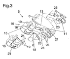
- the flap device consists 5 from the valve shaft 6 with valve bodies arranged thereon 8, wherein between each flap body 8 is arranged in each case a two-part bearing element 10 is.
- Each bearing element 10 has a first bearing part 11 and a second bearing part 15, between which a flap shaft 6 is rotatably mounted. The attachment follows in the way that the first bearing parts 11 with their to the wall surfaces 14 of the housing 2 of the air intake duct 1 corresponding wall surfaces 13 the housing 2 are placed. Subsequently, the valve shaft 6 with the arranged flap body 8 in corresponding semicircular receptacles 23rd the first bearing parts 11 inserted.
- the entire flap device 5 For attachment of these first bearing parts 11 and Thus, the entire flap device 5, the second bearing parts 15, which again have a semicircular receptacle 24, each on the first bearing parts 11 or the flap shaft 6 is placed, wherein the second bearing parts 15th in turn to the wall surfaces 18 of the first bearing parts 11 corresponding Have wall surfaces 16.
- the first bearing parts 11 have holes 25 through the pins 19 of the second bearing members 15 are passed through. The attachment the entire flap device 5 is again by hot deformation of the Projections or pins 19 facing away from the bearing elements 10 Side of the housing 2, which in turn indentations 21 in the housing.
- each second bearing part 15 At least two preferably, as shown in Figure 3, three projections 19 which are inserted through the holes 20.
- a stop is provided on the second bearing parts 15 26 is arranged to limit the flap angle.
- the respective last bearing element 10 of the flap device 5 be made in one piece and only two projections or pins 19th in the installed state through the corresponding holes 20 in Housing 2 range, since this part in a shaft 6 with valve bodies arranged thereon 8 can be attached from the side.
- first and the second bearing part 11, 15 can further, if desired, corresponding projections and receptacles are arranged so that the two bearing parts can optionally be clipped together.
Landscapes
- Engineering & Computer Science (AREA)
- Chemical & Material Sciences (AREA)
- Combustion & Propulsion (AREA)
- Mechanical Engineering (AREA)
- General Engineering & Computer Science (AREA)
- Control Of Throttle Valves Provided In The Intake System Or In The Exhaust System (AREA)
- Lift Valve (AREA)
- Characterised By The Charging Evacuation (AREA)
Abstract
Description
Claims (11)
- Klappenlagerbefestigung an einem Luftansaugkanalsystem einer Verbrennungskraftmaschine, wobei das Luftansaugkanalsystem ein zumindest einteiliges Gehäuse aufweist, in dem eine Klappenvorrichtung angeordnet ist, welche eine Klappenwelle, auf der zumindest ein Klappenkörper angeordnet ist und zumindest ein Lagerelement, in dem die Klappenwelle gelagert ist, aufweist, wobei die Klappenvorrichtung über das zumindest eine Lagerelement im Gehäuse des Luftansaugkanalsystems befestigt ist, dadurch gegenzeichnet, dass das zumindest eine Lagerelement (10) Vorsprünge (19) aufweist, welche im zusammen gebauten Zustand durch korrespondierende Öffnungen (20) im Gehäuse (2) des Luftansaugkanalsystems (1) reichen, wobei durch Warmverformung der Vorsprünge (19) das zumindest eine Lagerelement (10) am Gehäuse (2) befestigt ist.
- Klappenlagerbefestigung nach Anspruch 1, dadurch gegenzeichnet, dass das Gehäuse (2) um die Öffnungen (20), durch die die Vorsprünge (19) des zumindest einen Lagerelementes (10) reichen, Einbuchtungen (21) aufweist, so dass nach dem Warmverformen der Vorsprünge (19) die Oberfläche (22) des Gehäuses (2) im wesentlichen glatt ist.
- Klappenlagerbefestigung nach einem der Ansprüche 1 oder 2, dadurch gekennzeichnet, dass jedes einzelne Lagerelement (10), welches am Gehäuse (2) über die Vorsprünge (19) befestigt ist, zumindest zwei Vorsprünge (19) aufweist.
- Klappenlagerbefestigung nach einem der vorhergehenden Ansprüche, dadurch gekennzeichnet, dass die Vorsprünge (19) als kreisförmige Stifte und die Öffnungen (20) als Bohrungen ausgebildet sind.
- Klappenlagerbefestigung nach einem der vorhergehenden Ansprüche, dadurch gekennzeichnet, dass das Gehäuse (2) des Luftansaugkanalsystems (1) aus Druckguß insbesondere Magenesiumdruckguß, und die Klappenvorrichtung (5) aus Kunststoff hergestellt ist.
- Klappenlagerbefestigung nach einem der vorhergehenden Ansprüche, dadurch gekennzeichnet, dass das Gehäuse (2) des Luftansaugkanalsystems (1) mehrteilig ausgeführt ist, wobei die Klappenvorrichtung (5) an einem oberen Einlegeteil (4) des Gehäuses (2) befestigt ist.
- Klappenlagerbefestigung nach einem der vorhergehenden Ansprüche, dadurch gekennzeichnet, dass zumindest eine zum Gehäuse gerichtete geformte Wandfläche (13, 16) des Lagerelementes (10) zumindest teilweise gegen eine korrespondierend geformte Wandfläche (14, 17) des Gehäuses (2) des Luftansaugkanalsystems (1) anliegt.
- Klappenlagerbefestigung nach einem der vorhergehenden Ansprüche, dadurch gekennzeichnet, dass die Klappenvorrichtung (5) in einem ein- oder mehrteiligen Lagerrahmen (15) angeordnet ist, in dem die Klappenwelle (6, 7) mit dem zumindest einen Klappenkörper (8) gelagert ist, wobei die Klappenvorrichtung (5) vormontiert in das Gehäuse des Luftansaugkanalsystems einlegbar ist.
- Klappenlagerbefestigung nach einem der Ansprüche 1 bis 7, dadurch gekennzeichnet, dass die Klappenvorrichtung (5) für jeden Klappenkörper (8) zumindest ein Lagerelement (10) aufweist, welches ein- oder mehrteilig ausgeführt ist.
- Klappenlagerbefestigung nach einem der Ansprüche 1 bis 7, dadurch gekennzeichnet, dass die Klappenvorrichtung (5) zumindest ein Lagerelement (10) aufweist, welches mehrteilig ausgeführt ist, wobei ein oder mehrere erste Lagerteile (11), die die Klappenwelle (6, 7) ganz oder teilweise umschließen, mit einer geformten Wandfläche (13) gegen korrespondierend geformte Wandflächen (14) des Gehäuses des Luftansaugkanalsystems anliegen und ein oder mehrere zweite Lagerteile (15), welche die Vorsprünge (19) aufweisen, derart auf dem oder den ersten Lagerteilen (11) aufliegen, dass durch das Warmverformen der Vorsprünge (19), welche durch die Öffnungen (20) im Gehäuse (2) reichen, das oder die ersten Lagerteile (11) formschlüssig im Gehäuse (2) befestigt sind.
- Klappenlagerbefestigung nach einem der Ansprüche 8 oder 10, dadurch gekennzeichnet, dass zwei Klappenwellen (6, 7) über einen ein- oder mehrteiligen Lagerrahmen (15) im Gehäuse (2) befestigt sind.
Applications Claiming Priority (2)
| Application Number | Priority Date | Filing Date | Title |
|---|---|---|---|
| DE102004010555A DE102004010555B4 (de) | 2004-03-04 | 2004-03-04 | Klappenlagerbefestigung |
| DE102004010555 | 2004-03-04 |
Publications (2)
| Publication Number | Publication Date |
|---|---|
| EP1571312A2 true EP1571312A2 (de) | 2005-09-07 |
| EP1571312A3 EP1571312A3 (de) | 2010-10-20 |
Family
ID=34745386
Family Applications (1)
| Application Number | Title | Priority Date | Filing Date |
|---|---|---|---|
| EP05000301A Withdrawn EP1571312A3 (de) | 2004-03-04 | 2005-01-08 | Klappenlagerbefestigung |
Country Status (3)
| Country | Link |
|---|---|
| US (1) | US7213556B2 (de) |
| EP (1) | EP1571312A3 (de) |
| DE (1) | DE102004010555B4 (de) |
Families Citing this family (2)
| Publication number | Priority date | Publication date | Assignee | Title |
|---|---|---|---|---|
| EP1764492B2 (de) † | 2005-09-20 | 2016-01-27 | Mahle International GmbH | Frischgasanlage für eine Brennkraftmaschine |
| DE102007027123A1 (de) | 2007-06-13 | 2009-01-15 | Volkswagen Ag | Schaltsaugrohr für eine Brennkraftmaschine |
Citations (7)
| Publication number | Priority date | Publication date | Assignee | Title |
|---|---|---|---|---|
| EP0201180A1 (de) * | 1985-05-04 | 1986-11-12 | Austin Rover Group Limited | Saugrohranlage für V-Brennkraftmaschinen |
| DE19614474A1 (de) | 1996-04-12 | 1997-10-16 | Pierburg Ag | Luftansaugkanalsystem für Brennkraftmaschinen |
| US5813380A (en) | 1993-12-10 | 1998-09-29 | Mitsubishi Jidosha Kogyo Kabushiki Kaisha | Suction control device for multiple cylinder internal combustion engine |
| DE19944623A1 (de) | 1999-09-17 | 2001-03-22 | Pierburg Ag | Luftansaugkanalsystem für Brennkraftmaschinen |
| DE19946861A1 (de) | 1999-09-30 | 2001-04-19 | Audi Ag | Ansaugsystem einer Brennkraftmaschine |
| DE10143386A1 (de) | 2001-09-05 | 2003-04-03 | Zf Sachs Ag | Parksperre für ein Kraftfahrzeug |
| DE10236393A1 (de) | 2002-08-08 | 2004-03-04 | Pierburg Gmbh | Ansaugkanalsystem |
Family Cites Families (6)
| Publication number | Priority date | Publication date | Assignee | Title |
|---|---|---|---|---|
| US4907547A (en) * | 1989-02-21 | 1990-03-13 | Siemens-Bendix Automotive Electronics L.P. | One-piece wave deflector for I.C. engine intake system |
| FR2724418B1 (fr) * | 1994-09-09 | 1997-01-17 | Magneti Marelli France | Tubulure d'admission d'air a volets pivotants pour moteur a combustion interne |
| DE19729335A1 (de) * | 1997-07-09 | 1999-01-14 | Pierburg Ag | Anordnung zur Lagerung einer mehrere Schaltklappen tragenden Schaltklappenwelle |
| DE29922274U1 (de) * | 1999-12-17 | 2001-04-19 | IAV GmbH Ingenieurgesellschaft Auto und Verkehr, 10587 Berlin | Mehrteilige Saugrohreinheit |
| DE60120913T2 (de) * | 2000-01-20 | 2007-01-11 | Siemens Vdo Automotive Inc. | Ultraschallschweissverbindung für selbstschneidende schraubenhaltevorrichtung |
| DE10143384C1 (de) * | 2001-09-05 | 2003-04-17 | Pierburg Gmbh | Schaltklappeneinrichtung |
-
2004
- 2004-03-04 DE DE102004010555A patent/DE102004010555B4/de not_active Expired - Fee Related
-
2005
- 2005-01-08 EP EP05000301A patent/EP1571312A3/de not_active Withdrawn
- 2005-03-03 US US11/070,222 patent/US7213556B2/en not_active Expired - Fee Related
Patent Citations (7)
| Publication number | Priority date | Publication date | Assignee | Title |
|---|---|---|---|---|
| EP0201180A1 (de) * | 1985-05-04 | 1986-11-12 | Austin Rover Group Limited | Saugrohranlage für V-Brennkraftmaschinen |
| US5813380A (en) | 1993-12-10 | 1998-09-29 | Mitsubishi Jidosha Kogyo Kabushiki Kaisha | Suction control device for multiple cylinder internal combustion engine |
| DE19614474A1 (de) | 1996-04-12 | 1997-10-16 | Pierburg Ag | Luftansaugkanalsystem für Brennkraftmaschinen |
| DE19944623A1 (de) | 1999-09-17 | 2001-03-22 | Pierburg Ag | Luftansaugkanalsystem für Brennkraftmaschinen |
| DE19946861A1 (de) | 1999-09-30 | 2001-04-19 | Audi Ag | Ansaugsystem einer Brennkraftmaschine |
| DE10143386A1 (de) | 2001-09-05 | 2003-04-03 | Zf Sachs Ag | Parksperre für ein Kraftfahrzeug |
| DE10236393A1 (de) | 2002-08-08 | 2004-03-04 | Pierburg Gmbh | Ansaugkanalsystem |
Also Published As
| Publication number | Publication date |
|---|---|
| US20050196309A1 (en) | 2005-09-08 |
| DE102004010555B4 (de) | 2006-02-09 |
| EP1571312A3 (de) | 2010-10-20 |
| US7213556B2 (en) | 2007-05-08 |
| DE102004010555A1 (de) | 2005-09-29 |
Similar Documents
| Publication | Publication Date | Title |
|---|---|---|
| EP1175556B1 (de) | Schaltklappenverband aus montagegespritzten schaltklappen oder klappenmodulen | |
| EP0799142B1 (de) | Scheibenwischeranlage mit einem geräusch- bzw. schwingungsdämpfenden befestigungsmittel | |
| DE102012209074A1 (de) | Aktive luftleitverschlüsse | |
| DE10226594A1 (de) | Regelklappe mit eingespritzter Welle | |
| DE102007063255A1 (de) | Lagereinrichtung | |
| WO2001009493A2 (de) | Saugrohranlage | |
| DE102008051041B4 (de) | Turbolader mit Befestigungselementen zum Befestigen von Schaufellagerringen einer variablen Turbinengeometrie VTG | |
| DE102017117142A1 (de) | Kühlmodullager und Baugruppe mit KFZ-Kühlmodul und Kühlmodullager | |
| DE102018209091A1 (de) | Nockenwelleneinheit für fahrzeug | |
| DE19834835B4 (de) | Kanalsystem, insbesondere Saugrohr für eine Brennkraftmaschine | |
| EP1101021B1 (de) | Kanalsystem, insbesondere saugrohr für eine brennkraftmaschine | |
| DE102004010555B4 (de) | Klappenlagerbefestigung | |
| DE102011004066A1 (de) | 3-Wellen-Verstellgetriebe mit veränderter Masseverteilung und Verfahren zur Herstellung eines Wellgenerators | |
| DE3937339A1 (de) | Befestigungselement und verfahren fuer seine produktion | |
| DE60000806T2 (de) | Kunststoff-Drosselklappenstutzen | |
| DE10143384C1 (de) | Schaltklappeneinrichtung | |
| DE102011079620A1 (de) | Verfahren zum Fügen von Getriebebauteilen | |
| DE102004045730B3 (de) | Klappenvorrichtung für ein Luftansaugkanalsystem einer Verbrennungskraftmaschine | |
| EP1251253B1 (de) | Schaltverband zum Verschluss von Saugkanälen einer Ansaugvorrichtung | |
| DE102004041880B4 (de) | Klappen-Anordnung | |
| EP1038110B1 (de) | Formschlussverbindung | |
| DE10318430B4 (de) | Gehäuse einer elektrischen Maschine bzw. elektrischen Maschine mit einem Gehäuse zur Anbringung eines Anbauelementes an das Gehäuse | |
| EP2564077A1 (de) | Bauteil für einen kraftwagen | |
| DE102012212735B4 (de) | Mehrteilige Schwungmasse | |
| DE19949416A1 (de) | Gehäuse für eine Brennkraftmaschine |
Legal Events
| Date | Code | Title | Description |
|---|---|---|---|
| PUAI | Public reference made under article 153(3) epc to a published international application that has entered the european phase |
Free format text: ORIGINAL CODE: 0009012 |
|
| 17P | Request for examination filed |
Effective date: 20050108 |
|
| AK | Designated contracting states |
Kind code of ref document: A2 Designated state(s): AT BE BG CH CY CZ DE DK EE ES FI FR GB GR HU IE IS IT LI LT LU MC NL PL PT RO SE SI SK TR |
|
| AX | Request for extension of the european patent |
Extension state: AL BA HR LV MK YU |
|
| PUAL | Search report despatched |
Free format text: ORIGINAL CODE: 0009013 |
|
| AK | Designated contracting states |
Kind code of ref document: A3 Designated state(s): AT BE BG CH CY CZ DE DK EE ES FI FR GB GR HU IE IS IT LI LT LU MC NL PL PT RO SE SI SK TR |
|
| AX | Request for extension of the european patent |
Extension state: AL BA HR LV MK YU |
|
| 17Q | First examination report despatched |
Effective date: 20110322 |
|
| AKX | Designation fees paid |
Designated state(s): AT BE BG CH CY CZ DE DK EE ES FI FR GB GR HU IE IS IT LI LT LU MC NL PL PT RO SE SI SK TR |
|
| STAA | Information on the status of an ep patent application or granted ep patent |
Free format text: STATUS: THE APPLICATION IS DEEMED TO BE WITHDRAWN |
|
| 18D | Application deemed to be withdrawn |
Effective date: 20121009 |