EP1570933B1 - Vorrichtung mit einer Löseeinheit zum Betätigen einer Spannvorrichtung für Werkzeuge - Google Patents
Vorrichtung mit einer Löseeinheit zum Betätigen einer Spannvorrichtung für Werkzeuge Download PDFInfo
- Publication number
- EP1570933B1 EP1570933B1 EP05003751A EP05003751A EP1570933B1 EP 1570933 B1 EP1570933 B1 EP 1570933B1 EP 05003751 A EP05003751 A EP 05003751A EP 05003751 A EP05003751 A EP 05003751A EP 1570933 B1 EP1570933 B1 EP 1570933B1
- Authority
- EP
- European Patent Office
- Prior art keywords
- releasing
- housing
- motor
- spindle
- releasing unit
- Prior art date
- Legal status (The legal status is an assumption and is not a legal conclusion. Google has not performed a legal analysis and makes no representation as to the accuracy of the status listed.)
- Expired - Lifetime
Links
- 230000008878 coupling Effects 0.000 claims description 51
- 238000010168 coupling process Methods 0.000 claims description 51
- 238000005859 coupling reaction Methods 0.000 claims description 51
- 238000006073 displacement reaction Methods 0.000 claims description 5
- 238000006243 chemical reaction Methods 0.000 claims 2
- 230000001419 dependent effect Effects 0.000 claims 2
- 238000005259 measurement Methods 0.000 claims 1
- 238000000034 method Methods 0.000 description 3
- 230000008569 process Effects 0.000 description 3
- 238000001514 detection method Methods 0.000 description 2
- 238000011109 contamination Methods 0.000 description 1
- 238000010586 diagram Methods 0.000 description 1
- 239000000428 dust Substances 0.000 description 1
- 230000001050 lubricating effect Effects 0.000 description 1
- 238000005461 lubrication Methods 0.000 description 1
- 230000007257 malfunction Effects 0.000 description 1
- 238000012544 monitoring process Methods 0.000 description 1
- 238000000465 moulding Methods 0.000 description 1
- 210000002445 nipple Anatomy 0.000 description 1
- 230000004044 response Effects 0.000 description 1
- 230000000284 resting effect Effects 0.000 description 1
- 230000007704 transition Effects 0.000 description 1
- 230000001960 triggered effect Effects 0.000 description 1
Images


Classifications
-
- B—PERFORMING OPERATIONS; TRANSPORTING
- B23—MACHINE TOOLS; METAL-WORKING NOT OTHERWISE PROVIDED FOR
- B23B—TURNING; BORING
- B23B31/00—Chucks; Expansion mandrels; Adaptations thereof for remote control
- B23B31/02—Chucks
- B23B31/24—Chucks characterised by features relating primarily to remote control of the gripping means
- B23B31/26—Chucks characterised by features relating primarily to remote control of the gripping means using mechanical transmission through the working-spindle
- B23B31/261—Chucks characterised by features relating primarily to remote control of the gripping means using mechanical transmission through the working-spindle clamping the end of the toolholder shank
- B23B31/265—Chucks characterised by features relating primarily to remote control of the gripping means using mechanical transmission through the working-spindle clamping the end of the toolholder shank by means of collets
-
- B—PERFORMING OPERATIONS; TRANSPORTING
- B23—MACHINE TOOLS; METAL-WORKING NOT OTHERWISE PROVIDED FOR
- B23B—TURNING; BORING
- B23B31/00—Chucks; Expansion mandrels; Adaptations thereof for remote control
- B23B31/02—Chucks
- B23B31/24—Chucks characterised by features relating primarily to remote control of the gripping means
- B23B31/28—Chucks characterised by features relating primarily to remote control of the gripping means using electric or magnetic means in the chuck
-
- B—PERFORMING OPERATIONS; TRANSPORTING
- B23—MACHINE TOOLS; METAL-WORKING NOT OTHERWISE PROVIDED FOR
- B23B—TURNING; BORING
- B23B2260/00—Details of constructional elements
- B23B2260/062—Electric motors
-
- B—PERFORMING OPERATIONS; TRANSPORTING
- B23—MACHINE TOOLS; METAL-WORKING NOT OTHERWISE PROVIDED FOR
- B23B—TURNING; BORING
- B23B2270/00—Details of turning, boring or drilling machines, processes or tools not otherwise provided for
- B23B2270/09—Details relating to unclamping
-
- Y—GENERAL TAGGING OF NEW TECHNOLOGICAL DEVELOPMENTS; GENERAL TAGGING OF CROSS-SECTIONAL TECHNOLOGIES SPANNING OVER SEVERAL SECTIONS OF THE IPC; TECHNICAL SUBJECTS COVERED BY FORMER USPC CROSS-REFERENCE ART COLLECTIONS [XRACs] AND DIGESTS
- Y10—TECHNICAL SUBJECTS COVERED BY FORMER USPC
- Y10T—TECHNICAL SUBJECTS COVERED BY FORMER US CLASSIFICATION
- Y10T408/00—Cutting by use of rotating axially moving tool
- Y10T408/94—Tool-support
- Y10T408/95—Tool-support with tool-retaining means
-
- Y—GENERAL TAGGING OF NEW TECHNOLOGICAL DEVELOPMENTS; GENERAL TAGGING OF CROSS-SECTIONAL TECHNOLOGIES SPANNING OVER SEVERAL SECTIONS OF THE IPC; TECHNICAL SUBJECTS COVERED BY FORMER USPC CROSS-REFERENCE ART COLLECTIONS [XRACs] AND DIGESTS
- Y10—TECHNICAL SUBJECTS COVERED BY FORMER USPC
- Y10T—TECHNICAL SUBJECTS COVERED BY FORMER US CLASSIFICATION
- Y10T409/00—Gear cutting, milling, or planing
- Y10T409/30—Milling
- Y10T409/309352—Cutter spindle or spindle support
- Y10T409/309408—Cutter spindle or spindle support with cutter holder
- Y10T409/309464—Cutter spindle or spindle support with cutter holder and draw bar
Definitions
- the invention relates to a device with a release unit for operating a clamping device for tools according to the preamble of claim 1.
- a device is known from US-A-4,750,850 known.
- the tool spindle usually has a HSK holder for the tools, which are drawn into the spindle via a collet and clamped with a high axial pull-in force. Due to the axial movement of the tension rod collet segments are pressed by means of a seated on the tension rod cone piece to the outside. The collet elements engage behind a clamping surface on the tool, which is drawn through the tension rod into the spindle and tensioned. The axial movement of the tension rod is carried out in the tensioning direction by a spring assembly, for example by a cup spring package, mechanically and thus very securely and reliably.
- the tension rod must be adjusted against the spring force to the front.
- the collet segments are released so that they can pivot inwards.
- the tool is then ejected on the last remainder of the travel by the tie rod from the tool holder.
- the release unit is provided, which is formed by a hydraulically actuated release unit in the manner of a hydraulic cylinder.
- a part of the release unit is arranged axially displaceably in a receptacle and is supported axially with a coupling ring on a seated in the tool spindle coupling screw.
- the hydraulic solution is complicated and expensive due to the need for a hydraulic unit with pump, oil reservoir, valve block and the necessary piping. In addition, leaks can lead to malfunction. If the tool spindle is driven by belts, the hydraulic lines must be disconnected when changing the belt, which is difficult even when using hydraulic quick-release couplings and sometimes results in contamination by oil.
- the pneumatic solution does not work with the medium oil, but otherwise has the same disadvantages as the hydraulic solution.
- the pneumatically operating release unit due to the relatively low pressures at the high forces required either very large builds or expensive special solutions, such as tandem cylinder or pressure booster, are necessary.
- the invention has the object of providing the generic device in such a way that it is simple, inexpensive and compact.
- the drive is formed by an electric motor, which can be simple, inexpensive and compact and only requires an electrical supply line for operation.
- the effort for hydraulic units and piping is eliminated.
- the dissolving unit according to the invention is preferably used in molding machines.
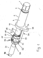
- the stationary motorized release unit described below can be solved tools 1, which are clamped in an interface 2 of a tool spindle 3 in a known manner.
- the tool spindle 3 has a spindle sleeve 4 (FIG. Fig. 1 ), in which a spindle shaft 5 is rotatably mounted.
- a tension rod 6 is housed in a known manner, which is surrounded over part of its length in a known manner by a spring assembly 7.
- the spring assembly 7 is advantageously made of disc springs.
- the spring assembly is supported at one end via a guide plate 8 at a radially inwardly projecting shoulder 9 in the inner wall of the spindle shaft 5 off.
- the spring assembly 7 is supported via a disc 10 on the end face of a pressure piece 11, which is designed as a sleeve and projects through a coupling screw 12 which is screwed into the end facing away from the interface 2 of the tool spindle 3 end of the spindle shaft 5.
- the over the coupling screw 12 outwardly projecting end of the pressure member 11 has a radially outwardly directed flange 13 acts on him the release unit when the clamped in the interface 2 tool 1 is to be solved.
- the interface 2 is advantageously designed as an HSK interface and has a cone-shaped tool holder 14, in which the tool 1 engages with a corresponding conical shaft 15.
- collets 16 are mounted in the spindle shaft 5 in a known manner, which engage behind the tool shank 15 in the clamping position and pull the tool 1 into the tool holder 14 and tighten.
- the clamping force is applied by the spring assembly 7.
- the tool 1 is pulled so far into the spindle shaft 5 until it rests against a flat end face 17 of the spindle shaft 5 with great force.
- the collets 16 are by a cone piece 18 in the in Fig. 9 pivoted clamping position shown pivoted.
- the cone piece 18 is firmly seated on the tension rod 6.
- the cone piece 18 is screwed onto the tension rod 6. If the tension rod 6 under the force of the spring assembly 7 in Fig. 9 shifted to the right in the spindle shaft 5, it spreads the tie rods 16 radially outward, which engage behind the tool shank 15. Will the tension rod 6 in a manner to be described by the release unit against the force of the spring assembly 7 in Fig. 9 shifted to the left, the cone piece 18 releases so much space that the collets 16 pivot inward and can release the tool shank 15.
- the cone piece 18 At the end of the displacement movement, the tool 1 comes out of the spindle shaft 5 which, with its shaft 15, sits self-lockingly in the cone seat 14 of the interface 2.
- a holder 19 On the spindle sleeve 4 is a holder 19 ( Fig. 1 ), which is part of a holding device 20. With her a release unit 21 is held, with the voltage of the tools 1 can be solved in a manner to be described later.
- the tool spindle 3 and the release unit 21 are axially behind each other ( Fig. 1 ) and coaxial with each other.
- a drive 22 for the release unit 21 is connected.
- the holding device 20 has a support 23, on which the release unit 21 is mounted resting and which protrudes perpendicularly from the holder 19.
- the holder 19 has a radially projecting eye 24 with a threaded bore 25, through which a (not shown) Axialverstellspindel protrudes, with which the unit of the tool spindle 3, holding device 20 and release unit 21 on a carrier (not shown) can be adjusted axially.
- the spindle sleeve 4 surrounds the spindle shaft 5 at its front region.
- the spindle shaft 5 has greater wall thickness than in the adjoining area ( Fig. 9 ), rotatably on a pulley 26 ( Fig. 1 ) sits.
- a pulley 26 For rotationally fixed connection with the pulley 26 of the wall thickness thinner part of the spindle shaft 5 with at least one positive locking element 27 (FIG. Fig. 9 ), which establishes the rotationally fixed connection to the pulley 26.
- the pulley 26 With a pulley nut 28, the pulley 26 is axially secured on the spindle shaft 5 ( Fig. 4 ).
- the pulley nut 28 is screwed onto the end of the spindle shaft 5 facing the release unit 21.
- the pulley 26 With its other end, the pulley 26 is located at the interposition of bearings (not shown) on a radially outwardly directed collar 29 (FIG. Fig. 9 ), which at the transition from thinner is provided in the thicker wall portion of the spindle shaft 5.
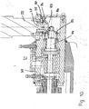
- FIG. 4 and 5 show the coupling screw 12 and the pressure member 11 axially over the spindle shaft 5 in the release unit 21.
- the pressure member 11 is compared to the coupling screw 12 so far moved towards the release unit 21 that the flange 13 of the pressure member 11 in the normal position ( Fig. 4 and 5 ) Distance from the coupling screw 12 has.
- the release unit 21 is mounted on the holding device 20 so that the coupling screw 12 and the pressure piece 11 protrude into a housing 30 of the release unit 21.
- a coupling ring 31 which with fastening screws 32 (FIG. Fig. 5 ) is attached to the housing front.
- the coupling ring 31 has threaded holes 33 into which the fastening screws 32 are screwed with their free end. So that the coupling ring 31 can be dismantled when the release unit 21 is mounted, the fastening screws 32 can be actuated from the opposite side of the housing 30.
- the housing has 30 recesses 34 which receive the screw heads 35 which rest against the bottom of the recesses 34.
- the coupling screw 12 is surrounded by the coupling ring 31 with little play.
- the coupling screw 12 is provided at the free, outside the tool spindle 3 lying end with a radially outwardly directed flange 36. He lies in the in the Fig. 4 and 5 shown basic position of the release unit 21 with axial distance an axially projecting collar 37 of the coupling ring 31 opposite.
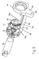
- the coupling ring 31 can be removed after loosening the fastening screws 32, it is designed to be split and has two ring parts 31a, 31b ( Fig. 2 ), which are each mounted with an axial pivot axis 38, 39 on the end face of the housing 30 pivotally.
- the pivot axes 38, 39 may be formed for example by fitting screws, which are inserted into corresponding openings in the end face of the housing 30. After loosening the fastening screws 32, the approximately semicircular ring parts 31a, 31b on the pivot axes 38, 39 are moved so far that the collar 37 emerges from the housing 30. Then, the ring members 31a, 31b can be pivoted about the pivot axes 38, 39 to the outside, so that the release unit 21 can be removed.
- the ring members 31a, 31b of the coupling ring 31 are not pivotally provided, but can be screwed only to the housing 30 and unscrew from it.
- the two ring members 31a, 31b are held together as a unit, the coupling ring 31 is provided in its outer surface with an annular groove 40 into which an elastic ring, preferably an O-ring, can be inserted, which holds the two ring parts 31a, 31b together.
- a discharge nut 41 is housed, which rests against the inner wall 42 of the housing 30.
- the ejection nut 41 has a central threaded through hole 43 into which a threaded spindle 44 engages. It is supported by thrust bearings 45, 46 in the housing 30.
- the threaded spindle 44 is coupled to a drive shaft 47 of the drive 22.
- the ejection nut 41 is displaced axially in the direction of the pressure piece 11 or away from it in the housing 30.
- the ejection nut 41 has a radially projecting torque arm 48 (FIG. Fig. 4 ), with their radially outer end in an in Axially extending slot 49 of the housing 30 engages.
- the width of this slot 49 corresponds to the cross-sectional width of the torque arm 48 in the engagement region.
- the torque arm 48 has a bolt 50 mounted in the ejection nut 41 and projecting radially above it, which may be screwed or pressed into the ejection nut 41.
- On the bolt 50 is seated a bushing 51, which is guided almost free of play in the slot 49 of the housing 30.
- the length of the axially extending slot 49 corresponds at least to the maximum displacement of the ejection nut 41 in the housing 30th
- the housing 30 of the release unit 21 is seated in a receiving flange 52, which is fastened to the holding device 20.
- the housing 30 is axially displaceable relative to the receiving flange 52 to a limited extent when the tool 1 clamped in the tool spindle 3 is to be released.
- the housing 30 is loaded by at least one spring 53, preferably a plate spring, in the direction of the drive 22 to the right.
- the spring 53 is supported on the receiving flange 52 and a securing ring 54, which sits on the outside of the housing 30.
- the drive 22 is attached. It rests with a motor flange plate 55 on the front side of the housing 30 and is fastened with screws 56 on the housing 30.
- the flange plate 55 itself is screwed with screws 57 on the front side of a motor housing 58.
- the flange plate 55 has in the amount of the fastening screws 32 lying axial through holes 59 ( Fig. 5 ), so that the mounting screws 32 are accessible even when mounted flange 55 from the outside.
- the passage openings 59 are located in a radially projecting beyond the motor housing 58 area.
- the threaded spindle 44 has a lying in the area outside of the ejection nut 41 collar 60, on which a thrust bearing 45 is axially supported. On the opposite side, the thrust bearing 45 is supported on a radially inwardly projecting shoulder surface 61 of the housing 30.
- the axially adjacent thrust bearing 46 is supported axially on a further radially inwardly projecting shoulder surface 62 of the housing 30 and on a nut 64 screwed onto the threaded spindle 44.
- the release unit 21 is provided with two sensors 65 and 66 ( Fig. 4 ) projecting radially from the release unit 21.
- the sensor 65 protrudes in the height of the pressure piece 11 in the housing 30 and is held by a sensor plate 67 which is fixed by at least one screw 68 on the housing 30 adjacent to the coupling ring 31.
- the other sensor 66 is seated in a sensor plate 69, which is fastened with at least one screw 70 on the receiving flange 52. Both sensors 65, 66 are advantageously inductively operating sensors.
- the sensor 65 has two functions. When the tool 1 is properly clamped in the tool spindle 3, the flange 13 of the pressure member 11 is in the in the Fig. 4 and 5 shown position in which the sensor 65 detects a button 71 of the Druck thoroughlyflansches 13. The button 71 is formed by the lateral surface of the Druck Anlagenflansches 13.
- the sensor 65 also has the task of monitoring the ejection process of the tool 1 from the tool spindle 3.
- the sensor 66 serves to turn off the drive 22 when the housing 30 is in its normal position according to the Fig. 4 and 5 located.
- the switch-off process is triggered by a button 74, which connects to an outside recess 75 in the housing 30 in the direction of the drive 22.
- the sensors 65, 66 can be advantageously limited in the axial direction of the housing 30 and the receiving flange 52, so that a simple positionally accurate positioning of the sensors 65, 66 is ensured relative to the buttons 71 and 74.
- the Fig. 4 and 5 show the initial position of the release unit 21 when the tool 1 is properly clamped in the tool spindle 3.
- the motor 22 is turned off, so that the threaded spindle 44 does not rotate.
- the flange 36 of the coupling screw 12 has axial distance from the collar 37 of the coupling ring 31.
- the opposing support surfaces 76, 77 of collar 37 and flange 36 touch each other in this position Not.
- the coupling screw 12, which is rotatably connected to the spindle shaft 5 freely rotate about its axis when the spindle shaft 5 rotates.
- the coupling ring 31 surrounds the coupling screw 12 with little radial clearance, the rotational movement of the coupling screw 12 is also not hindered by the coupling ring 31.
- the low clearance leads to a good seal of the interior of the release unit 21 and thus prevents the entry of dirt, dust, chips and the like.
- the drive of the spindle shaft 5 is first turned off, so that they and thus also the coupling screw 12 and the pressure piece 11 stand still. Subsequently, the motor 22 is turned on, so that the drive shaft 47 and the rotatably connected to it threaded spindle 44 are rotatably driven. The threaded spindle 44 is rotated so that the ejection nut 41 is displaced in the direction of the pressure piece 11 in the housing 30.
- the torque arm 48 ensures that the ejection nut 41 reliably displaced axially and not turned around its axis.
- the ejection nut 41 is further displaced in the direction of the tool spindle 3 until the drive motor 22 is automatically switched off when an adjustable maximum current is exceeded.
- This maximum current occurs when the pressure piece 11 with its flange 13 at the bottom 78 of a front-side recess 79 (FIG. Fig. 5 ) of the coupling screw 12 comes to rest.
- the coupling screw 12 thus forms a stop for the axial displacement of the pressure piece 11 and the ejection nut 41 and thereby ensures a defined position of the tension rod 6 with the cone piece 18 for ejecting and inserting the tool 1.
- This release position is in Fig. 6 shown.
- the housing 30 is displaced relative to the receiving flange 52.
- the cone piece 18 on the tension rod 6 releases the collets 16, so that they can be pivoted into the position releasing the tool 1.
- the tool 1 is ejected on the last piece of travel of the tension rod 6 from the tool holder 14 of the spindle shaft 5.
- the drive motor 22 is switched off when a maximum current is exceeded. But it is also possible to use the sensor 65 to switch off the motor during the release process. He then gives a shutdown signal to the motor 22, if a button 80 provided on the ejection nut 41 (FIG. Fig. 6 ) enters the detection range of the sensor 65.
- the tool 1 After the tool 1 has been ejected from the tool holder 14, it can be removed from the tool spindle 3. In the tool holder 14, a new tool 1 can then be used.
- the motor 20 is then switched in the reverse direction, so that the threaded spindle 44 rotates so that the ejection nut 41 back into the in the Fig. 4 and 5 shown release position is moved.
- the spring assembly 7 moves the tension rod 6 and thus the pressure piece 11 in the direction toward the release unit 21, as the ejection nut 41 moves back in the housing 30. In this way, the new tool 1 is clamped in the tool holder 14. Once the torque arm 48 with the head 72 of the bolt 50 at the in Fig.
- the button 80 of the ejection nut 41 comes out of the measuring range of the sensor 65, while the button 71 of the pressure piece 12 enters the detection range of the sensor 65 when the tool 1 is properly tensioned. Now the basic position according to the Fig. 4 and 5 reached. The sensor 65 then outputs an enable signal for switching on the tool spindle 3.
- the sensor 66 is fixedly arranged on the receiving flange 52 in the exemplary embodiment. But it is also possible to form the sensor 66 with the ejection nut 41 ride.
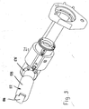
- the Fig. 3 and 10 show an embodiment that differs from the embodiment described above in that the motor 22 is not connected in the longitudinal direction of the release unit 21, but is at right angles to her. For this reason, the motor shaft 47 ( Fig. 10 ) via a bevel gear 83 with the threaded spindle 44 drivingly connected. On the motor shaft 47 sits a bevel gear 84 which meshes with a rotationally fixed on the threaded spindle 44 bevel gear 85.
- the flange plate 55 is in contrast to the previous embodiment not flanged to the end face of the housing 30, but on its lateral surface having a corresponding flattening.
- the front side of the housing 30 of the release unit 21 is closed by a cover 86.
- the rotatably seated on the motor shaft 47 bevel gear 84 is axially supported by a needle bearing 87.
- a connector 88 is provided at the free end of the motor housing 58.
- the embodiment according to the Fig. 3 and 10 is characterized by a short length. It can be used, for example, for vertical spindles on moulders.
- the release unit 21 is the same design as the previous embodiment.
- a lubricating nipple 89 is provided on the receiving flange 52, connect to the lubrication holes 90 to 92. They pass through the receiving flange 52, the housing 30 and the ejection nut 41. In this way, the ejection nut 41 and the threaded spindle 44 can be lubricated.
- FIGS. 11, 12 and 13 show a part of the preferred control for the release unit.
- the drive 22 ( FIGS. 11 and 12 ) is operated with a motor current I mot .
- the motor consists in the replacement diagram of an inductance L mot and a resistor R mot , which is variable depending on the engine temperature. In series with the motor, a measuring resistor R mess 95 is connected. This is much smaller dimensioned than the motor resistance R mot , whereby the engine is not significantly affected in its performance.
- a voltage U mess which is a controller 96 is supplied. It contains a comparator 97, in which the voltage U mess is compared with a reference voltage U ref . As soon as the voltage U mess ⁇ the reference voltage U ref , the comparator 97 supplies a signal 98 to a shutdown module 99. It generates a shutdown signal with which the switching element 93 is actuated and shuts off the motor.
- the voltage U mess is proportional to the motor current I mot , which in turn is proportional to the engine torque M mot .
- the maximum possible voltage U mess can be set and thus the switch-off current of the motor. This ensures that the motor is loaded only up to its permissible motor current and motor torque.
- the measuring resistor R mess 95 is substantially smaller than the motor resistance R mot , so that the drive 22 is also protected against overloading.
Landscapes
- Engineering & Computer Science (AREA)
- Mechanical Engineering (AREA)
- Gripping On Spindles (AREA)
- Details Of Spanners, Wrenches, And Screw Drivers And Accessories (AREA)
- Gear Transmission (AREA)
- Milling, Drilling, And Turning Of Wood (AREA)
- Finish Polishing, Edge Sharpening, And Grinding By Specific Grinding Devices (AREA)
Description
- Die Erfindung betrifft eine Vorrichtung mit einer Löseeinheit zum Betätigen einer Spannvorrichtung für Werkzeuge nach dem Oberbegriff des Anspruches 1. Eine solche Vorrichtung ist aus der
US-A-4,750,850 bekannt. - Mit Spannvorrichtungen werden Werkzeuge in einer Schnittstelle einer Werkzeugspindel eingespannt. Die Werkzeugspindel hat in der Regel eine HSK-Aufnahme für die Werkzeuge, die über eine Spannzange in die Spindel eingezogen und mit einer hohen axialen Einzugskraft gespannt werden. Durch die axiale Bewegung der Spannstange werden Spannzangensegmente mittels eines auf der Spannstange sitzenden Konusstückes nach außen gedrückt. Die Spannzangenelemente hintergreifen eine Spannfläche am Werkzeug, das durch die Spannstange in die Spindel eingezogen und gespannt wird. Die axiale Bewegung der Spannstange wird in Spannrichtung von einem Federpaket, zum Beispiel von einem Tellerfederpaket, mechanisch und damit sehr sicher und zuverlässig durchgeführt.
- Um das Werkzeug zu lösen, muß die Spannstange gegen die Federkraft nach vorn verstellt werden. Hierbei werden die Spannzangensegmente so freigegeben, daß sie nach innen schwenken können. Das Werkzeug wird dann auf dem letzten Rest des Verfahrweges durch die Spannstange aus der Werkzeugaufnahme ausgestoßen.
- Zum axialen Verschieben der Spannstange für die Freigabe des Werkzeuges ist die Löseeinheit vorgesehen, die durch eine hydraulisch betätigbare Löseeinheit nach Art eines Hydraulikzylinders ausgebildet ist. Um beim Lösen auf die Spindellagerung keine bzw. nur eine geringe Kraft auszuüben, ist ein Teil der Löseeinheit in einer Aufnahme axial verschieblich angeordnet und stützt sich mit einem Kupplungsring an einer in der Werkzeugspindel sitzenden Kupplungsschraube axial ab. Dadurch erfolgt der Kraftfluß beim Lösen des Werkzeuges nicht über die Lager, sondern über diese Abstützung.
- Es ist auch bekannt, ähnliche Löseeinheiten pneumatisch zu betätigen.
- Die hydraulische Lösung ist aufgrund des Bedarfs einer Hydraulikeinheit mit Pumpe, Ölbehälter, Ventilblock und der notwendigen Verrohrung aufwendig und teuer. Außerdem können Leckagen zu Funktionsstörungen führen. Wird die Werkzeugspindel durch Riemen angetrieben, müssen bei einem Riemenwechsel die Hydraulikleitungen getrennt werden, was selbst beim Einsatz hydraulischer Schnellkupplungen schwierig ist und zum Teil zu Verschmutzungen durch Öl führt.
- Die pneumatische Lösung arbeitet zwar nicht mit dem Medium Öl, hat aber ansonsten die gleichen Nachteile wie die hydraulische Lösung. Hinzu kommt, daß die pneumatisch arbeitende Löseeinheit aufgrund der relativ niedrigen Drücke bei den hohen notwendigen Kräften entweder sehr groß baut oder teure Sonderlösungen, wie Tandemzylinder oder Druckübersetzer, notwendig sind.
- Der Erfindung liegt die Aufgabe zugrunde, die gattungsgemäße Vorrichtung so auszubilden, daß sie einfach, preiswert und kompakt ausgebildet ist.
- Diese Aufgabe wird bei der gattungsgemäßen Löseeinheit erfindungsgemäß mit den kennzeichnenden Merkmalen des Anspruches 1 gelöst.
- Bei der erfindungsgemäßen Löseeinheit wird unter anderem der Antrieb durch einen Elektromotor gebildet, der einfach, preiswert und kompakt gebaut werden kann und lediglich eine elektrische Zuleitung für den Betrieb benötigt. Der Aufwand für Hydraulikaggregate und für eine Verrohrung entfällt. Die erfindungsgemäße Löseeinheit wird bevorzugt in Kehlmaschinen eingesetzt.
- Weitere Merkmale der Erfindung ergeben sich aus den weiteren Ansprüchen, der Beschreibung und den Zeichnungen.
- Die Erfindung wird anhand zweier in den Zeichnungen dargestellter Ausführungsformen näher erläutert. Es zeigen
- Fig. 1
- in perspektivischer Darstellung eine erfindungsgemäße Löseeinheit, die sich zwischen einem Motor und einer Werkzeugspindel mit Werkzeugspanneinrichtung befindet,
- Fig. 2
- in perspektivischer Darstellung die erfindungsgemäße Löseeinheit mit Antrieb,
- Fig. 3
- in einer Darstellung entsprechend
Fig. 2 die erfindungsgemäße Löseeinheit, deren Antrieb rechtwinklig zur Löseeinheit angeordnet ist, - Fig. 4
- in einem Schnitt längs der Linie A-A in
Fig. 7 die erfindungsgemäße Löseeinheit in ihrer Grundstellung, - Fig. 5
- in einem Schnitt längs der Linie C-C in
Fig. 7 die erfindungsgemäße Löseeinheit in ihrer Grundstellung, - Fig. 6
- in einem Schnitt längs der Linie A-A in
Fig. 7 die erfindungsgemäße Löseeinheit in Lösestellung, - Fig. 7
- eine Stirnansicht der erfindungsgemäßen Löseeinheit,
- Fig. 8
- einen Schnitt längs der Linie B-B in
Fig. 4 , - Fig. 9
- im Axialschnitt die Spanneinrichtung gemäß
Fig. 1 , - Fig. 10
- einen Längsschnitt durch die erfindungsgemäße Löseeinheit gemäß
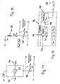
Fig. 3 , - Fig. 11
- in schematischer Darstellung eine Schaltung des Antriebes der erfindungsgemäßen Löseeinheit,
- Fig. 12
- ein Ersatzschaltbild des Motors gemäß
Fig. 11 , - Fig. 13
- in schematischer Darstellung eine Steuerung der erfindungsgemäßen Löseeinheit.
- Mit der im folgenden beschriebenen stationären motorischen Löseeinheit lassen sich Werkzeuge 1 lösen, die in eine Schnittstelle 2 einer Werkzeugspindel 3 in bekannter Weise eingespannt sind. Die Werkzeugspindel 3 hat eine Spindelhülse 4 (
Fig. 1 ), in der eine Spindelwelle 5 drehbar gelagert ist. In der Spindelwelle 5 ist in bekannter Weise eine Spannstange 6 untergebracht, die über einen Teil ihrer Länge in bekannter Weise von einem Federpaket 7 umgeben ist. Das Federpaket 7 besteht vorteilhaft aus Tellerfedern. Das Federpaket stützt sich an einem Ende über eine Führungsscheibe 8 an einer radial nach innen ragenden Schulter 9 in der Innenwand der Spindelwelle 5 ab. Am gegenüberliegenden Ende stützt sich das Federpaket 7 über eine Scheibe 10 an der Stirnseite eines Druckstückes 11 ab, das als Hülse ausgebildet ist und durch eine Kupplungsschraube 12 ragt, die in das von der Schnittstelle 2 der Werkzeugspindel 3 abgewandte Ende der Spindelwelle 5 geschraubt ist. Das über die Kupplungsschraube 12 nach außen ragende Ende des Druckstückes 11 hat einen radial nach außen gerichteten Flansch 13. Auf ihn wirkt die Löseeinheit, wenn das in die Schnittstelle 2 eingespannte Werkzeug 1 gelöst werden soll. - Die Schnittstelle 2 ist vorteilhaft als HSK-Schnittstelle ausgebildet und hat eine konusförmige Werkzeugaufnahme 14, in die das Werkzeug 1 mit einem entsprechenden kegelförmigen Schaft 15 eingreift.
- Im Bereich der Schnittstelle 2 sind in der Spindelwelle 5 in bekannter Weise Spannzangen 16 gelagert, die den Werkzeugschaft 15 in der Spannstellung hintergreifen und das Werkzeug 1 in die Werkzeugaufnahme 14 ziehen und spannen. Die Spannkraft wird durch das Federpaket 7 aufgebracht. Das Werkzeug 1 wird so weit in die Spindelwelle 5 gezogen, bis es an einer ebenen Stirnfläche 17 der Spindelwelle 5 mit großer Kraft anliegt.
- Die Spannzangen 16 werden durch ein Konusstück 18 in die in
Fig. 9 dargestellte Spannstellung geschwenkt. Das Konusstück 18 sitzt fest auf der Spannstange 6. Vorzugsweise ist das Konusstück 18 auf die Spannstange 6 geschraubt. Wird die Spannstange 6 unter der Kraft des Federpaketes 7 inFig. 9 nach rechts in der Spindelwelle 5 verschoben, spreizt es die Spannstangen 16 radial nach außen, die den Werkzeugschaft 15 hintergreifen. Wird die Spannstange 6 in noch zu beschreibender Weise durch die Löseeinheit gegen die Kraft des Federpaketes 7 inFig. 9 nach links verschoben, gibt das Konusstück 18 so viel Raum frei, daß die Spannzangen 16 nach innen schwenken und den Werkzeugschaft 15 freigeben können. Das Konusstück 18 stößt am Ende der Verschiebebewegung das Werkzeug 1 aus der Spindelwelle 5 aus, das mit seinem Schaft 15 selbsthemmend in der Konusaufnahme 14 der Schnittstelle 2 sitzt. - An der Spindelhülse 4 ist ein Halter 19 (
Fig. 1 ) befestigt, der Teil einer Haltevorrichtung 20 ist. Mit ihr wird eine Löseeinheit 21 gehalten, mit der in noch zu beschreibender Weise die Spannung der Werkzeuge 1 gelöst werden kann. Die Werkzeugspindel 3 und die Löseeinheit 21 liegen axial hintereinander (Fig. 1 ) sowie koaxial zueinander. An die von der Werkzeugspindel 3 abgewandte Seite der Löseeinheit 21 ist ein Antrieb 22 für die Löseeinheit 21 angeschlossen. - Die Haltevorrichtung 20 hat eine Auflage 23, auf der die Löseeinheit 21 aufliegend befestigt ist und die senkrecht vom Halter 19 absteht. Der Halter 19 hat ein radial abstehendes Auge 24 mit einer Gewindebohrung 25, durch die eine (nicht dargestellte) Axialverstellspindel ragt, mit der die Einheit aus Werkzeugspindel 3, Haltevorrichtung 20 und Löseeinheit 21 an einem (nicht dargestellten) Träger axial verstellt werden kann.
- Die Spindelhülse 4 umgibt die Spindelwelle 5 an ihrem vorderen Bereich. In diesem Bereich hat die Spindelwelle 5 größere Wandstärke als im daran anschließenden Bereich (
Fig. 9 ), auf dem drehfest eine Riemenscheibe 26 (Fig. 1 ) sitzt. Zur drehfesten Verbindung mit der Riemenscheibe 26 ist der in der Wandstärke dünnere Teil der Spindelwelle 5 mit wenigstens einem Formschlußelement 27 (Fig. 9 ) versehen, das die drehfeste Verbindung zur Riemenscheibe 26 herstellt. Mit einer Riemenscheibenmutter 28 ist die Riemenscheibe 26 axial auf der Spindelwelle 5 gesichert (Fig. 4 ). Die Riemenscheibenmutter 28 wird auf das der Löseeinheit 21 zugewandte Ende der Spindelwelle 5 geschraubt. Mit ihrem anderen Ende liegt die Riemenscheibe 26 unter Zwischenlage von (nicht dargestellten) Lagern an einem radial nach außen gerichteten Bund 29 (Fig. 9 ) an, der am Übergang vom dünneren in den dickeren Wandbereich der Spindelwelle 5 vorgesehen ist. - Wie die
Fig. 4 und5 zeigen, ragen die Kupplungsschraube 12 und das Druckstück 11 axial über die Spindelwelle 5 in die Löseeinheit 21. Das Druckstück 11 ist gegenüber der Kupplungsschraube 12 so weit in Richtung auf die Löseeinheit 21 verschoben, daß der Flansch 13 des Druckstückes 11 in der Grundstellung (Fig. 4 und5 ) Abstand von der Kupplungsschraube 12 hat. - Die Löseeinheit 21 wird so auf der Haltevorrichtung 20 montiert, daß die Kupplungsschraube 12 und das Druckstück 11 in ein Gehäuse 30 der Löseeinheit 21 ragen. An der der Werkzeugspindel 3 zugewandten Stirnseite des Gehäuses 30 liegt ein Kupplungsring 31 an, der mit Befestigungsschrauben 32 (
Fig. 5 ) an der Gehäusestirnseite befestigt ist. Der Kupplungsring 31 hat Gewindebohrungen 33, in die die Befestigungsschrauben 32 mit ihrem freien Ende geschraubt sind. Damit der Kupplungsring 31 bei montierter Löseeinheit 21 demontiert werden kann, sind die Befestigungsschrauben 32 von der gegenüberliegenden Seite des Gehäuses 30 aus betätigbar. In diesem Bereich hat das Gehäuse 30 Vertiefungen 34, die die Schraubenköpfe 35 aufnehmen, die am Boden der Vertiefungen 34 anliegen. - Die Kupplungsschraube 12 wird mit geringem Spiel vom Kupplungsring 31 umgeben. Die Kupplungsschraube 12 ist am freien, außerhalb der Werkzeugspindel 3 liegenden Ende mit einem radial nach außen gerichteten Flansch 36 versehen. Er liegt in der in den
Fig. 4 und5 dargestellten Grundstellung der Löseeinheit 21 mit axialem Abstand einem axial vorstehenden Bund 37 des Kupplungsringes 31 gegenüber. - Damit der Kupplungsring 31 nach dem Lösen der Befestigungsschrauben 32 abgenommen werden kann, ist er geteilt ausgebildet und weist zwei Ringteile 31a, 31b (
Fig. 2 ) auf, die mit jeweils einer axialen Schwenkachse 38, 39 an der Stirnseite des Gehäuses 30 schwenkbar gelagert sind. Die Schwenkachsen 38, 39 können beispielsweise durch Paßschrauben gebildet sein, die in entsprechende Öffnungen in der Stirnseite des Gehäuses 30 eingesetzt werden. Nach dem Lösen der Befestigungsschrauben 32 können die etwa halbkreisförmigen Ringteile 31a, 31b auf den Schwenkachsen 38, 39 so weit verschoben werden, daß der Bund 37 aus dem Gehäuse 30 heraustritt. Dann können die Ringteile 31a, 31b um die Schwenkachsen 38, 39 nach außen geschwenkt werden, so daß sich die Löseeinheit 21 abnehmen läßt. - Bei einer zweiten Ausführungsform sind die Ringteile 31a, 31b des Kupplungsringes 31 nicht schwenkbar vorgesehen, sondern lassen sich lediglich an das Gehäuse 30 anschrauben bzw. von ihm abschrauben. Damit die beiden Ringteile 31a, 31b als Einheit zusammengehalten werden, ist der Kupplungsring 31 in seiner Mantelfläche mit einer Ringnut 40 versehen, in die ein elastischer Ring, vorzugsweise ein O-Ring, eingelegt werden kann, der die beiden Ringteile 31a, 31b zusammenhält.
- Im Gehäuse 30 der Löseeinheit 21 ist eine Ausstoßmutter 41 untergebracht, die an der Innenwand 42 des Gehäuses 30 anliegt. Die Ausstoßmutter 41 hat eine zentrale durchgehende Gewindebohrung 43, in die eine Gewindespindel 44 eingreift. Sie ist mit Axiallagern 45, 46 im Gehäuse 30 abgestützt. Die Gewindespindel 44 ist mit einer Antriebswelle 47 des Antriebs 22 gekuppelt. Je nach Drehrichtung der Gewindespindel 44 wird die Ausstoßmutter 41 in Richtung auf das Druckstück 11 oder von ihm weg axial im Gehäuse 30 verschoben.
- Die Ausstoßmutter 41 hat eine radial abstehende Drehmomentenstütze 48 (
Fig. 4 ), die mit ihrem radial äußeren Ende in einen in Achsrichtung verlaufenden Schlitz 49 des Gehäuses 30 eingreift. Die Breite dieses Schlitzes 49 entspricht der Querschnittsbreite der Drehmomentenstütze 48 im Eingriffsbereich. Die Drehmomentenstütze 48 hat einen in der Ausstoßmutter 41 befestigten und radial über sie vorstehenden Bolzen 50, der in die Ausstoßmutter 41 geschraubt oder auch eingepreßt sein kann. Auf dem Bolzen 50 sitzt eine Buchse 51, die annähernd spielfrei im Schlitz 49 des Gehäuses 30 geführt ist. Die Länge des in Axialrichtung sich erstreckenden Schlitzes 49 entspricht mindestens dem maximalen Verschiebeweg der Ausstoßmutter 41 im Gehäuse 30. - Das Gehäuse 30 der Löseeinheit 21 sitzt in einem Aufnahmeflansch 52, der an der Haltevorrichtung 20 befestigt wird. Das Gehäuse 30 ist axial gegenüber dem Aufnahmeflansch 52 begrenzt verschiebbar, wenn das in die Werkzeugspindel 3 eingespannte Werkzeug 1 gelöst werden soll. Das Gehäuse 30 ist durch wenigstens eine Feder 53, vorzugsweise eine Tellerfeder, in Richtung auf den Antrieb 22 nach rechts belastet. Die Feder 53 stützt sich am Aufnahmeflansch 52 sowie einem Sicherungsring 54 ab, der auf der Außenseite des Gehäuses 30 sitzt.
- An dem von der Werkzeugspindel 3 abgewandten Ende der Löseeinheit 21 ist der Antrieb 22 befestigt. Er liegt mit einer Motorflanschplatte 55 an der Stirnseite des Gehäuses 30 an und ist mit Schrauben 56 am Gehäuse 30 befestigt. Die Flanschplatte 55 selbst ist mit Schrauben 57 an der Stirnseite eines Motorgehäuses 58 angeschraubt. Die Flanschplatte 55 weist in Höhe der Befestigungsschrauben 32 liegende axiale Durchgangsöffnungen 59 auf (
Fig. 5 ), damit die Befestigungsschrauben 32 auch bei montierter Flanschplatte 55 von außen zugänglich sind. Die Durchgangsöffnungen 59 befinden sich in einem radial über das Motorgehäuse 58 überstehenden Bereich. - Die Gewindespindel 44 hat einen im Bereich außerhalb der Ausstoßmutter 41 liegenden Bund 60, an dem das eine Axiallager 45 axial abgestützt ist. Auf der gegenüberliegenden Seite stützt sich das Axiallager 45 an einer radial nach innen ragenden Schulterfläche 61 des Gehäuses 30 ab.
- Das axial benachbarte Axiallager 46 stützt sich an einer weiteren radial nach innen ragenden Schulterfläche 62 des Gehäuses 30 sowie an einer auf die Gewindespindel 44 geschraubten Mutter 64 axial ab.
- Die Löseeinheit 21 ist mit zwei Sensoren 65 und 66 versehen (
Fig. 4 ), die radial von der Löseeinheit 21 abstehen. Der Sensor 65 ragt in Höhe des Druckstückes 11 in das Gehäuse 30 und ist durch eine Sensorplatte 67 gehalten, die durch wenigstens eine Schraube 68 auf dem Gehäuse 30 benachbart zum Kupplungsring 31 befestigt ist. - Der andere Sensor 66 sitzt in einer Sensorplatte 69, die mit wenigstens einer Schraube 70 auf dem Aufnahmeflansch 52 befestigt ist. Beide Sensoren 65, 66 sind vorteilhaft induktiv arbeitende Sensoren. Der Sensor 65 hat zwei Funktionen. Wenn das Werkzeug 1 ordnungsgemäß in die Werkzeugspindel 3 eingespannt ist, befindet sich der Flansch 13 des Druckstückes 11 in der in den
Fig. 4 und5 dargestellten Position, in der der Sensor 65 eine Schaltfläche 71 des Druckstückflansches 13 erfaßt. Die Schaltfläche 71 wird durch die Mantelfläche des Druckstückflansches 13 gebildet. Der Sensor 65 hat außerdem die Aufgabe, den Ausstoßvorgang des Werkzeuges 1 aus der Werkzeugspindel 3 zu überwachen. - Der Sensor 66 dient dazu, den Antrieb 22 dann abzuschalten, wenn sich das Gehäuse 30 in seiner Grundstellung gemäß den
Fig. 4 und5 befindet. Der Abschaltvorgang wird durch eine Schaltfläche 74 ausgelöst, die an eine außenseitige Vertiefung 75 im Gehäuse 30 in Richtung auf den Antrieb 22 anschließt. - Die Sensoren 65, 66 lassen sich vorteilhaft in Achsrichtung des Gehäuses 30 bzw. des Aufnahmeflansches 52 begrenzt einstellen, so daß eine einfache lagegenaue Positionierung der Sensoren 65, 66 relativ zu den Schaltflächen 71 und 74 gewährleistet ist.
- Die
Fig. 4 und5 zeigen die Ausgangslage der Löseeinheit 21, wenn das Werkzeug 1 ordnungsgemäß in die Werkzeugspindel 3 eingespannt ist. Der Motor 22 ist abgeschaltet, so daß die Gewindespindel 44 nicht dreht. Die Ausstoßmutter 41 hat axialen Abstand vom Flansch 13 des Druckstückes 11. In dieser Grundstellung hat der Flansch 36 der Kupplungsschraube 12 axialen Abstand vom Bund 37 des Kupplungsringes 31. Die einander gegenüberliegenden Abstützflächen 76, 77 von Bund 37 und Flansch 36 berühren in dieser Stellung einander nicht. Dadurch kann die Kupplungsschraube 12, die drehfest mit der Spindelwelle 5 verbunden ist, ungehindert um ihre Achse drehen, wenn die Spindelwelle 5 dreht. Da der Kupplungsring 31 die Kupplungsschraube 12 mit geringem radialen Spiel umgibt, wird die Drehbewegung der Kupplungsschraube 12 auch nicht durch den Kupplungsring 31 behindert. Das geringe Spiel führt aber zu einer guten Abdichtung des Innenraumes der Löseeinheit 21 und verhindert damit den Zutritt von Schmutz, Staub, Spänen und dergleichen. - Soll das Werkzeug 1 der Werkzeugspindel 3 entnommen werden, wird zunächst der Antrieb der Spindelwelle 5 abgeschaltet, so daß sie und damit auch die Kupplungsschraube 12 und das Druckstück 11 still stehen. Anschließend wird der Motor 22 eingeschaltet, so daß die Antriebswelle 47 und die drehfest mit ihr verbundene Gewindespindel 44 drehbar angetrieben werden. Die Gewindespindel 44 wird so gedreht, daß die Ausstoßmutter 41 in Richtung auf das Druckstück 11 im Gehäuse 30 verschoben wird. Die Drehmomentenstütze 48 stellt sicher, daß die Ausstoßmutter 41 zuverlässig axial verschoben und nicht um ihre Achse gedreht wird. Sobald die Kupplungsmutter 41 mit ihrer Stirnseite am Flansch 13 des Druckstückes 11 anliegt, wird nunmehr das komplette Gehäuse 30 mit der Gewindespindel 44 und dem Antriebsmotor 22 in den
Fig. 4 und5 nach rechts bewegt, bis die radiale, durch die Stirnseite des Bundes 37 des Kupplungsringes 31 gebildete Abstützfläche 76 an der radialen Abstützfläche 77 des Flansches 36 der Kupplungsschraube 12 anliegt. In dieser Anschlußstellung der beiden Abstützflächen 76, 77 ist der Kraftfluß geschlossen. Da die Gewindespindel 44 durch den Antriebsmotor 22 weiter angetrieben wird, baut sich nunmehr die Kraft zum Zusammendrücken des Federpaketes 7 in der Werkzeugspindel 3 auf. Die Ausstoßmutter 41 wird weiter so lange in Richtung auf die Werkzeugspindel 3 verschoben, bis der Antriebsmotor 22 bei Überschreiten eines einstellbaren Maximalstromes automatisch abgeschaltet wird. Dieser maximale Strom tritt dann auf, wenn das Druckstück 11 mit seinem Flansch 13 am Boden 78 einer stirnseitigen Vertiefung 79 (Fig. 5 ) der Kupplungsschraube 12 zur Anlage kommt. Die Kupplungsschraube 12 bildet somit einen Anschlag für die axiale Verstellung des Druckstückes 11 und der Ausstoßmutter 41 und gewährleistet dadurch eine definierte Stellung der Spannstange 6 mit dem Konusstück 18 zum Ausstoßen und Einsetzen des Werkzeuges 1. Diese Lösestellung ist inFig. 6 dargestellt. Das Gehäuse 30 ist relativ zum Aufnahmeflansch 52 verschoben. Das Konusstück 18 auf der Spannstange 6 gibt die Spannzangen 16 frei, so daß sie in die das Werkzeug 1 freigebende Lage verschwenkt werden können. Das Werkzeug 1 wird auf dem letzten Stück des Verfahrweges der Spannstange 6 aus der Werkzeugaufnahme 14 der Spindelwelle 5 ausgestoßen. - Bei der beschriebenen Ausbildung wird der Antriebsmotor 22 bei Überschreiten eines Maximalstromes abgeschaltet. Es ist aber auch möglich, zum Abschalten des Motors beim Lösevorgang den Sensor 65 heranzuziehen. Er gibt dann ein Abschaltsignal an den Motor 22, wenn eine an der Ausstoßmutter 41 vorgesehene Schaltfläche 80 (
Fig. 6 ) in den Erfassungsbereich des Sensors 65 gelangt. - Nachdem das Werkzeug 1 aus der Werkzeugaufnahme 14 ausgestoßen worden ist, kann es der Werkzeugspindel 3 entnommen werden. In die Werkzeugaufnahme 14 kann anschließend ein neues Werkzeug 1 eingesetzt werden. Der Motor 20 wird dann in umgekehrter Drehrichtung geschaltet, so daß die Gewindespindel 44 so dreht, daß die Ausstoßmutter 41 zurück in die in den
Fig. 4 und5 dargestellte Lösestellung verschoben wird. Das Federpaket 7 verschiebt die Spannstange 6 und damit das Druckstück 11 in dem Maße in Richtung auf die Löseeinheit 21, wie sich die Ausstoßmutter 41 im Gehäuse 30 zurückbewegt. Auf diese Weise wird das neue Werkzeug 1 in der Werkzeugaufnahme 14 gespannt. Sobald die Drehmomentenstütze 48 mit dem Kopf 72 des Bolzens 50 an dem inFig. 6 rechten Rand 81 eines Schlitzes 82 im Aufnahmeflansch 52 zur Anlage kommt, wird das Gehäuse 30 mit dem Kupplungsring 31 wieder in Richtung auf die Werkzeugspindel 3 verschoben. Der Kopf 72 des Bolzens 50 verhindert ein Verdrehen des Gehäuses 30 gegenüber dem Aufnahmeflansch 52, in dem der Kopf 72 mit geringem Spiel im Schlitz 82 aufgenommen ist. Schließlich wird wieder die Lage gemäß denFig. 4 und5 erreicht, in der die Abstützflächen 76, 77 des Kupplungsringes 31 und des Druckstückes 12 Abstand voneinander haben. Sobald die Schaltfläche 74 des Gehäuses 30 in den Meßbereich des Sensors 66 gelangt (Fig. 4 ), wird der Antrieb 22 abgeschaltet. Da die Abstützflächen 76, 77 frei sind, kann die Spindelwelle 5 wieder frei drehen. Bei den beschriebenen Bewegungen kommt die Schaltfläche 80 der Ausstoßmutter 41 aus dem Meßbereich des Sensors 65, während die Schaltfläche 71 des Druckstückes 12 in den Erfassungsbereich des Sensors 65 gelangt, wenn das Werkzeug 1 richtig gespannt ist. Nunmehr ist die Grundstellung gemäß denFig. 4 und5 erreicht. Der Sensor 65 gibt dann ein Freigabesignal zum Einschalten der Werkzeugspindel 3. - Der Sensor 66 ist im Ausführungsbeispiel ortsfest am Aufnahmeflansch 52 angeordnet. Es ist aber auch möglich, den Sensor 66 mit der Ausstoßmutter 41 mitfahrend auszubilden.
- Die
Fig. 3 und10 zeigen eine Ausführungsform, die sich von dem zuvor beschriebenen Ausführungsbeispiel dadurch unterscheidet, daß der Motor 22 nicht in Längsrichtung an die Löseeinheit 21 anschließt, sondern rechtwinklig zu ihr liegt. Aus diesem Grunde ist die Motorwelle 47 (Fig. 10 ) über ein Kegelradgetriebe 83 mit der Gewindespindel 44 antriebsverbunden. Auf der Motorwelle 47 sitzt ein Kegelrad 84, das mit einem drehfest auf der Gewindespindel 44 sitzenden Kegelrad 85 kämmt. - Die Flanschplatte 55 ist im Unterschied zum vorigen Ausführungsbeispiel nicht an die Stirnseite des Gehäuses 30 angeflanscht, sondern an seiner Mantelfläche, die eine entsprechende Abflachung aufweist. Stirnseitig ist das Gehäuse 30 der Löseeinheit 21 durch einen Deckel 86 geschlossen. Das auf der Motorwelle 47 drehfest sitzende Kegelrad 84 ist durch ein Nadellager 87 axial abgestützt.
- Wie beim vorigen Ausführungsbeispiel ist am freien Ende des Motorgehäuses 58 ein Anschlußstecker 88 vorgesehen.
- Die Ausführungsform gemäß den
Fig. 3 und10 zeichnet sich durch eine kurze Baulänge aus. Sie kann beispielsweise für Vertikalspindeln bei Kehlmaschinen eingesetzt werden. - Die Löseeinheit 21 ist gleich ausgebildet wie das vorige Ausführungsbeispiel.
- Wie die
Fig. 1 und8 zeigen, ist am Aufnahmeflansch 52 ein Schmiernippel 89 vorgesehen, an den Schmierbohrungen 90 bis 92 anschließen. Sie durchsetzen den Aufnahmeflansch 52, das Gehäuse 30 und die Ausstoßmutter 41. Auf diese Weise können die Ausstoßmutter 41 und die Gewindespindel 44 geschmiert werden. - Die
Fig. 11, 12 und 13 zeigen einen Teil der bevorzugten Steuerung für die Löseeinheit. Der Antrieb 22 (Fig. 11 und 12 ) wird mit einem Motorstrom Imot betrieben. Mit zwei Schaltelementen 93, 94, die im Ausführungsbeispiel Relais sind, läßt sich die Drehrichtung des Antriebes 22 und damit die Drehrichtung der Gewindespindel 44 einstellen. Der Motor besteht im Ersatzschaubild aus einer Induktivität Lmot und einem Widerstand Rmot, der abhängig von der Motortemperatur veränderlich ist. In Reihe zum Motor ist ein Meßwiderstand Rmess 95 geschaltet. Dieser ist wesentlich kleiner dimensioniert als der Motorwiderstand Rmot, wodurch der Motor in seiner Leistung nicht wesentlich beeinträchtigt wird. - An dem Meßwiderstand Rmess 95 fällt in Abhängigkeit des Motorstromes Imot eine Spannung Umess ab, welche einer Steuerung 96 zugeführt wird. Sie enthält einen Vergleicher 97, in dem die Spannung Umess mit einer Referenzspannung Uref verglichen wird. Sobald die Spannung Umess ≥ der Referenzspannung Uref ist, liefert der Vergleicher 97 ein Signal 98 an ein Abschaltmodul 99. Es erzeugt ein Abschaltsignal, mit dem das Schaltelement 93 betätigt wird und den Motor abschaltet.
- Die Spannung Umess ist proportional dem Motorstrom Imot, der seinerseits proportional dem Motormoment Mmot ist. Über die Referenzspannung Uref kann die maximal mögliche Spannung Umess eingestellt werden und damit der Abschaltstrom des Motors. Dadurch ist gewährleistet, daß der Motor nur bis zu seinem zulässigen Motorstrom und Motormoment belastet wird.
- Da der Meßwiderstand Rmess 95 wesentlich kleiner ist als der Motorwiderstand Rmot, ist damit der Antrieb 22 außerdem vor Überlastung geschützt.
Claims (22)
- Vorrichtung mit einer Löseeinheit (21) zum Betätigen einer Spannvorrichtung für Werkzeuge, mit mindestens einem Löseelement (41), das durch einen Antrieb (22) aus einer Ruhestellung in eine Lösestellung verstellbar ist, in der es eine Spannstange (6) der Spannvorrichtung gegen eine Spannkraft in eine Freigabestellung verschiebt,
dadurch gekennzeichnet,
dass der Antrieb (22) ein Elektromotor ist, dass das Löseelement (41) axial verschiebbar ist, dass die Löseeinheit (21) wenigstens ein Kupplungselement (31) aufweist, das mit einem Gegenkupplungselement (12) einer Werkzeugspindel (3) zusammenwirkt, dass durch das Gegenkupplungselement (12) ein mit der Spannstange (6) fest verbundenes Druckstück (11) regt, das im Verschiebeweg des Löseelementes (41) liegt, und dass Abstützyflächen (76, 77) des Kupplungselementes (31) und des Gegenkupplungselementes (12) in der Spannstellung axialen Abstand voneinander haben, in der Lösestellung aber aneinander liegen und die Spannstange (6) gegen Federkraft in der Freigabestellung halten. - Vorrichtung nach Anspruch 1,
dadurch gekennzeichnet, dass die Achse des Motors (22) zumindest parallel, vorzugsweise fluchtend zur Achse der Löseeinheit (21) liegt. - Vorrichtung nach Anspruch 1,
dadurch gekennzeichnet, dass die Achse des Motors (22) winklig, vorzugsweise rechtwinklig zur Achse der Löseeinheit (21) liegt. - Vorrichtung nach Anspruch 1 oder 3,
dadurch gekennzeichnet, dass die Motorwelle (47) über ein Kegelgetriebe (84, 85) mit einer Antriebsspindel (44) der Löseeinheit (21) antriebsverbunden ist. - Vorrichtung nach Anspruch 1 oder 2,
dadurch gekennzeichnet, dass die Spannvorrichtung (6, 16), die Löseeinheit (21) und der Motor (22) axial hintereinander angeordnet sind. - Vorrichtung nach Anspruch 4 oder 5,
dadurch gekennzeichnet, dass das Löseelement (41) auf der Antriebsspindel (44) sitzt. - Vorrichtung nach einem der Ansprüche 4 bis 6,
dadurch gekennzeichnet, dass die Antriebsspindel (44) axial fest in einem Gehäuse (30) der Löseeinheit (21) angeordnet ist. - Vorrichtung nach einem der Ansprüche 4 bis 7,
dadurch gekennzeichnet, dass die Antriebsspindel (44) eine Gewindespindel ist, und dass vorteilhaft das Löseelement (41) in Gewindeeingriff auf der Antriebsspindel (44) sitzt. - Vorrichtung nach einem der Ansprüche 1 bis 8,
dadurch gekennzeichnet, dass das Löseelement (41) gegenüber dem Gehäuse (30) der Löseeinheit (21) gegen Verdrehen gesichert ist. - Vorrichtung nach einem der Ansprüche 1 bis 9,
dadurch gekennzeichnet, dass das Löseelement (41) mit mindestens einer Drehmomentenstütze (48) versehen ist, die vorteilhaft als ein radial vom Löseelement (41) abstehender Arm ausgebildet ist. - Vorrichtung nach Anspruch 10,
dadurch gekennzeichnet, dass das freie Ende der Drehmomentenstütze (48) in einem Schlitz (49) des Gehäuses (30) der Löseeinheit (21) axial geführt ist. - Vorrichtung nach einem der Ansprüche 1 bis 11,
dadurch gekennzeichnet, dass das Gehäuse (30) der Löseeinheit (21) in einer Aufnahme (52) aufgenommen ist, gegenüber der das Gehäuse (30) begrenzt axial verschiebbar ist. - Vorrichtung nach einem der Ansprüche 1 bis 12,
dadurch gekennzeichnet, dass das Kupplungselement (31) lösbar am Gehäuse (30) der Löseeinheit (21) vorgesehen ist. - Vorrichtung nach einem der Ansprüche 1 bis 13,
dadurch gekennzeichnet, dass das Kupplungselement (31) ein Kupplungsring ist und ein Gegenkupplungselement (12) der Werkzeugspindel (3) übergreift. - Vorrichtung nach einem der Ansprüche 1 bis 14, dadurch gekennzeichnet, dass das Kupplungselement (31) ein geteilter Kupplungsring ist.
- Vorrichtung nach Anspruch 15,
dadurch gekennzeichnet, dass die beiden Kupplungsringteile (31a, 31 b) um jeweils eine Achse (38, 39) schwenkbar am Gehäuse (30) der Löseeinheit (21) gelagert sind. - Vorrichtung nach einem der Ansprüche 1 bis 16,
dadurch gekennzeichnet, dass das Gegenkupplungselement (12) eine in eine Spindelwelle (5) der Werkzeugspindel (3) geschraubte Kupp-lungsschraube ist. - Vorrichtung nach einem der Ansprüche 1 bis 17,
dadurch gekennzeichnet, dass beim Auftreffen des Löseelementes (41) auf das Druckstück (11) das Gehäuse (30) mit Antriebsspindel (44) so weit axial verschiebbar ist, bis die Abstützflächen (76, 77) des Kupplungselementes (31) und des Gegenkupplungselementes (12) aneinander liegen. - Vorrichtung nach Anspruch 17 oder 18,
dadurch gekennzeichnet, dass nach der Anlage der Abstützflächen (76, 77) aneinander die Spannstange (6) zur Freigabe des Werkzeuges (1) durch das Löseelement (41) verschiebbar ist. - Vorrichtung nach einem der Ansprüche 1 bis 19,
dadurch gekennzeichnet, dass an einem Meßwiderstand (95) in Abhängigkeit des Motorstromes (Imot) eine Spannung (Umess) abfällt, die mit einer Referenzspannung (Uref) in einer Steuerung (96) verglichen wird, die in Abhängigkeit vom Vergleich ein Abschaltsignal (98) für den Motor (22) erzeugt. - Vorrichtung nach Anspruch 20,
dadurch gekennzeichnet, dass die Spannung (Umess) proportional dem Motorstrom (Imot) ist. - Vorrichtung nach Anspruch 20 oder 21,
dadurch gekennzeichnet, dass der Motorstrom (Imot) proportional dem Motormoment (Mmot) ist, und dass vorteilhaft der Motor (22) bei Überschreiten der Referenzspannung (Uref) abgeschaltet wird.
Applications Claiming Priority (2)
| Application Number | Priority Date | Filing Date | Title |
|---|---|---|---|
| DE102004011738A DE102004011738B4 (de) | 2004-03-03 | 2004-03-03 | Vorrichtung mit einer Löseeinheit zum Betätigen einer Spannvorrichtung für Werkzeuge |
| DE102004011738 | 2004-03-03 |
Publications (3)
| Publication Number | Publication Date |
|---|---|
| EP1570933A2 EP1570933A2 (de) | 2005-09-07 |
| EP1570933A3 EP1570933A3 (de) | 2008-01-23 |
| EP1570933B1 true EP1570933B1 (de) | 2010-03-31 |
Family
ID=34745444
Family Applications (1)
| Application Number | Title | Priority Date | Filing Date |
|---|---|---|---|
| EP05003751A Expired - Lifetime EP1570933B1 (de) | 2004-03-03 | 2005-02-22 | Vorrichtung mit einer Löseeinheit zum Betätigen einer Spannvorrichtung für Werkzeuge |
Country Status (8)
| Country | Link |
|---|---|
| US (1) | US7249919B2 (de) |
| EP (1) | EP1570933B1 (de) |
| CN (1) | CN1663741B (de) |
| AR (1) | AR048156A1 (de) |
| AT (1) | ATE462520T1 (de) |
| BR (1) | BRPI0500720A (de) |
| DE (2) | DE102004011738B4 (de) |
| TW (1) | TWI275434B (de) |
Families Citing this family (16)
| Publication number | Priority date | Publication date | Assignee | Title |
|---|---|---|---|---|
| DE10160705A1 (de) * | 2001-12-11 | 2003-06-26 | Paul Mueller Gmbh & Co Kg | Vorrichtung zur Befestigung eines Werkzeugs an einer Welle sowie Maschinenspindel mit einer derartigen Vorrichtung |
| DE102004051031B3 (de) | 2004-10-20 | 2006-04-27 | Ott-Jakob Gmbh & Co. Spanntechnik Kg | Spannvorrichtung |
| JP4846410B2 (ja) * | 2006-03-30 | 2011-12-28 | シチズンホールディングス株式会社 | 主軸頭装置及び工作機械 |
| CN101310902B (zh) * | 2007-05-24 | 2011-01-26 | 鸿准精密模具(昆山)有限公司 | 夹持装置及其使用方法 |
| US8769786B1 (en) * | 2009-03-24 | 2014-07-08 | Honda Motor Co., Ltd. | Trim and flame robot end effector with optional automatic blade change feature |
| KR101157324B1 (ko) * | 2009-12-18 | 2012-06-18 | 한화테크엠주식회사 | 서보모터를 이용한 척킹력 조정방법 |
| DE102010044783A1 (de) * | 2010-03-02 | 2011-09-08 | Grob-Werke Gmbh & Co. Kg | Bearbeitungsmaschine |
| DE102010021010A1 (de) * | 2010-03-02 | 2011-09-08 | Grob-Werke Gmbh & Co. Kg | Bearbeitungsmaschine |
| EP2495059B1 (de) * | 2011-03-01 | 2017-07-19 | Siemens Aktiengesellschaft | Werkzeuglösevorrichtung, Inbetriebnahmeverfahren und Betriebsverfahren |
| DE102011082828A1 (de) * | 2011-09-16 | 2013-03-21 | Zf Friedrichshafen Ag | Schalteinheit mit Spindeltrieb für ein Werkzeugmaschinengetriebe |
| DE102012105759A1 (de) * | 2012-06-29 | 2014-01-02 | Röhm Gmbh | Spannkopf |
| DE102014104285A1 (de) * | 2014-03-27 | 2015-10-01 | Röhm Gmbh | Spannfutter |
| DE102016009431A1 (de) * | 2016-07-29 | 2018-02-01 | Michael Weinig Ag | Spanneinrichtung für Werkzeuge |
| KR102360161B1 (ko) * | 2017-05-29 | 2022-02-09 | 현대자동차주식회사 | 스핀들 장치 및 그의 작동방법 |
| CN107234279B (zh) * | 2017-07-28 | 2024-02-02 | 昆山众异特机械工业有限公司 | 一种模具划线装置 |
| CN113001470B (zh) * | 2021-02-14 | 2022-08-30 | 株洲大众机械制造有限责任公司 | 一种便于单人使用的机械加工刀具更换用辅助装置 |
Family Cites Families (14)
| Publication number | Priority date | Publication date | Assignee | Title |
|---|---|---|---|---|
| DE1099309B (de) * | 1955-05-28 | 1961-02-09 | Karl Schmidt Ges Mit Beschraen | Vorrichtung zum Spannen von Werkstuecken, insbesondere bei Mehrspindelautomaten |
| DE1281783B (de) * | 1965-12-02 | 1968-10-31 | Froriep Gmbh Maschf | Verstellvorrichtung fuer die Spannbacken einer Planscheibe od. dgl. |
| US4913605A (en) * | 1984-07-30 | 1990-04-03 | Schwartzman Everett H | Integral spring flexure for use with high speed rotating shafts |
| DE3508231A1 (de) * | 1985-03-08 | 1986-09-11 | Karl Hertel GmbH, 8510 Fürth | Antriebseinheit fuer rotierende werkzeuge |
| FR2588492B1 (fr) * | 1985-10-14 | 1989-05-26 | Aerospatiale | Porte-outil de securite pour machine-outil |
| DE3629453A1 (de) * | 1986-08-29 | 1988-03-10 | Forkardt Paul Gmbh | Elektromechanische vorrichtung zum erzeugen einer axialkraft fuer die betaetigung von spannzeugen |
| US4750850A (en) * | 1987-05-01 | 1988-06-14 | Husted Royce Hill | Collet release mechanism for milling machine |
| US4804301A (en) * | 1988-02-24 | 1989-02-14 | Gte Valenite Corporation | Central drawbar coupling actuating mechanism |
| JP3475401B2 (ja) * | 1999-02-25 | 2003-12-08 | 東芝機械株式会社 | アングルヘッドの工具着脱装置 |
| JP4344442B2 (ja) * | 1999-12-17 | 2009-10-14 | 富士機械製造株式会社 | チャック装置 |
| EP1262264A4 (de) * | 2000-01-12 | 2004-05-26 | Mitsubishi Electric Corp | Schubumsetzer, methode und gerät zum steuern eines schubumsetzers |
| DE10101095A1 (de) * | 2001-01-12 | 2002-07-25 | Ortlieb Praez S Spannzeuge Gmb | Spanneinrichtung für Werkzeuge, Werkzeughalter oder dergleichen |
| DE10101093B4 (de) * | 2001-01-12 | 2009-10-22 | Ortlieb Präzisions-Spannzeuge GmbH + Co. | Spanneinrichtung für Werkzeuge, Werkzeughalter oder dergleichen |
| DE10160705A1 (de) * | 2001-12-11 | 2003-06-26 | Paul Mueller Gmbh & Co Kg | Vorrichtung zur Befestigung eines Werkzeugs an einer Welle sowie Maschinenspindel mit einer derartigen Vorrichtung |
-
2004
- 2004-03-03 DE DE102004011738A patent/DE102004011738B4/de not_active Expired - Fee Related
-
2005
- 2005-02-04 TW TW094103511A patent/TWI275434B/zh not_active IP Right Cessation
- 2005-02-16 AR ARP050100548A patent/AR048156A1/es unknown
- 2005-02-22 AT AT05003751T patent/ATE462520T1/de active
- 2005-02-22 DE DE502005009295T patent/DE502005009295D1/de not_active Expired - Lifetime
- 2005-02-22 EP EP05003751A patent/EP1570933B1/de not_active Expired - Lifetime
- 2005-03-02 BR BR0500720-8A patent/BRPI0500720A/pt not_active IP Right Cessation
- 2005-03-02 CN CN2005100528899A patent/CN1663741B/zh not_active Expired - Fee Related
- 2005-03-03 US US10/906,713 patent/US7249919B2/en not_active Expired - Lifetime
Also Published As
| Publication number | Publication date |
|---|---|
| CN1663741A (zh) | 2005-09-07 |
| AR048156A1 (es) | 2006-04-05 |
| US20050196247A1 (en) | 2005-09-08 |
| DE502005009295D1 (de) | 2010-05-12 |
| US7249919B2 (en) | 2007-07-31 |
| EP1570933A2 (de) | 2005-09-07 |
| CN1663741B (zh) | 2010-05-05 |
| DE102004011738A1 (de) | 2005-09-22 |
| EP1570933A3 (de) | 2008-01-23 |
| DE102004011738B4 (de) | 2010-01-07 |
| BRPI0500720A (pt) | 2005-11-08 |
| ATE462520T1 (de) | 2010-04-15 |
| TW200536640A (en) | 2005-11-16 |
| TWI275434B (en) | 2007-03-11 |
Similar Documents
| Publication | Publication Date | Title |
|---|---|---|
| EP1570933B1 (de) | Vorrichtung mit einer Löseeinheit zum Betätigen einer Spannvorrichtung für Werkzeuge | |
| EP1776202B1 (de) | Fördereinrichtung eines schweissdrahts | |
| DE4234115A1 (de) | Dosenverschliessmaschine | |
| EP2598271B1 (de) | Hydrodehnspannfutter | |
| CH619629A5 (de) | ||
| EP0368023A2 (de) | Werkzeugsystem | |
| EP1803518A2 (de) | Werkzeugkopf zur Aufnahme und zum Antrieb der Drehbewegung eines zweiseitig zu lagernden Werkzeuges sowie Werkzeug zum Einsatz in einem solchen Werkzeugkopf | |
| DE9016415U1 (de) | Handgeführte Elektrowerkzeugmaschine mit einer Einrichtung zum Einstellen des Drehmoments | |
| EP3403749A1 (de) | Gegenlager für bearbeitungsspindeln von bearbeitungsmaschinen und verfahren zum spannen von gegenlagern und werkzeugen | |
| EP0302187B1 (de) | Spanneinrichtung an Drehmaschinen mit einem Spannfutter | |
| DE2316605C2 (de) | Vorrichtung zum Spannen und Lösen von einen konischen Schaft aufweisenden, in eine Spindelaufnahme einsetzbaren Werkzeugen | |
| EP2616212A2 (de) | Sicherungs-spannvorrichtung | |
| DE2518626A1 (de) | Hydraulische lenkung | |
| EP3658318B1 (de) | Zerspanungswerkzeug mit einer justiereinrichtung | |
| WO2019020786A1 (de) | Zerspanungswerkzeug | |
| EP4135929B1 (de) | Vorrichtung und verfahren zum anschluss einer kühldüse an eine kühlschmiermittelzuführung | |
| DE8518206U1 (de) | Antriebseinheit für rotierende Schaftwerkzeuge | |
| EP0798064B1 (de) | Spannvorrichtung für scheibenförmige Werkzeuge | |
| DE2112016A1 (de) | Hydraulische Vorschubeinrichtung fuer Werkzeugmaschinen | |
| EP3403766A1 (de) | Klemmeinrichtung für wenigstens ein zu klemmendes bauteil | |
| EP2550461A1 (de) | Vorrichtung zum verriegeln eines axial verschiebbaren bauteils einer hydraulischen anlage | |
| DE4445611A1 (de) | Werkzeughalter, insbesondere Schnellwechselfutter | |
| DE3411542C2 (de) | Bearbeitungseinrichtung | |
| EP1153709A2 (de) | Zusatzwerkzeug für eine Fräsmaschine | |
| DE2412850A1 (de) | Einrichtung zum wechselweisen spannen und loesen des werkzeugschaftes an werkzeugmaschinen, insbesondere an bohr- und fraesmaschinen |
Legal Events
| Date | Code | Title | Description |
|---|---|---|---|
| PUAI | Public reference made under article 153(3) epc to a published international application that has entered the european phase |
Free format text: ORIGINAL CODE: 0009012 |
|
| AK | Designated contracting states |
Kind code of ref document: A2 Designated state(s): AT BE BG CH CY CZ DE DK EE ES FI FR GB GR HU IE IS IT LI LT LU MC NL PL PT RO SE SI SK TR |
|
| AX | Request for extension of the european patent |
Extension state: AL BA HR LV MK YU |
|
| PUAL | Search report despatched |
Free format text: ORIGINAL CODE: 0009013 |
|
| AK | Designated contracting states |
Kind code of ref document: A3 Designated state(s): AT BE BG CH CY CZ DE DK EE ES FI FR GB GR HU IE IS IT LI LT LU MC NL PL PT RO SE SI SK TR |
|
| AX | Request for extension of the european patent |
Extension state: AL BA HR LV MK YU |
|
| 17P | Request for examination filed |
Effective date: 20080529 |
|
| 17Q | First examination report despatched |
Effective date: 20080710 |
|
| R17C | First examination report despatched (corrected) |
Effective date: 20080728 |
|
| AKX | Designation fees paid |
Designated state(s): AT BE BG CH CY CZ DE DK EE ES FI FR GB GR HU IE IS IT LI LT LU MC NL PL PT RO SE SI SK TR |
|
| RTI1 | Title (correction) |
Free format text: APPARATUS WITH A RELEASING UNIT FOR THE ACTUATION OF A CLAMPING DEVICE FOR TOOLS |
|
| GRAP | Despatch of communication of intention to grant a patent |
Free format text: ORIGINAL CODE: EPIDOSNIGR1 |
|
| GRAS | Grant fee paid |
Free format text: ORIGINAL CODE: EPIDOSNIGR3 |
|
| GRAA | (expected) grant |
Free format text: ORIGINAL CODE: 0009210 |
|
| AK | Designated contracting states |
Kind code of ref document: B1 Designated state(s): AT BE BG CH CY CZ DE DK EE ES FI FR GB GR HU IE IS IT LI LT LU MC NL PL PT RO SE SI SK TR |
|
| REG | Reference to a national code |
Ref country code: CH Ref legal event code: EP Ref country code: GB Ref legal event code: FG4D Free format text: NOT ENGLISH |
|
| REG | Reference to a national code |
Ref country code: IE Ref legal event code: FG4D |
|
| REF | Corresponds to: |
Ref document number: 502005009295 Country of ref document: DE Date of ref document: 20100512 Kind code of ref document: P |
|
| REG | Reference to a national code |
Ref country code: NL Ref legal event code: VDEP Effective date: 20100331 |
|
| PG25 | Lapsed in a contracting state [announced via postgrant information from national office to epo] |
Ref country code: LT Free format text: LAPSE BECAUSE OF FAILURE TO SUBMIT A TRANSLATION OF THE DESCRIPTION OR TO PAY THE FEE WITHIN THE PRESCRIBED TIME-LIMIT Effective date: 20100331 |
|
| LTIE | Lt: invalidation of european patent or patent extension |
Effective date: 20100331 |
|
| PG25 | Lapsed in a contracting state [announced via postgrant information from national office to epo] |
Ref country code: FI Free format text: LAPSE BECAUSE OF FAILURE TO SUBMIT A TRANSLATION OF THE DESCRIPTION OR TO PAY THE FEE WITHIN THE PRESCRIBED TIME-LIMIT Effective date: 20100331 Ref country code: SI Free format text: LAPSE BECAUSE OF FAILURE TO SUBMIT A TRANSLATION OF THE DESCRIPTION OR TO PAY THE FEE WITHIN THE PRESCRIBED TIME-LIMIT Effective date: 20100331 Ref country code: PL Free format text: LAPSE BECAUSE OF FAILURE TO SUBMIT A TRANSLATION OF THE DESCRIPTION OR TO PAY THE FEE WITHIN THE PRESCRIBED TIME-LIMIT Effective date: 20100331 |
|
| REG | Reference to a national code |
Ref country code: IE Ref legal event code: FD4D |
|
| PG25 | Lapsed in a contracting state [announced via postgrant information from national office to epo] |
Ref country code: ES Free format text: LAPSE BECAUSE OF FAILURE TO SUBMIT A TRANSLATION OF THE DESCRIPTION OR TO PAY THE FEE WITHIN THE PRESCRIBED TIME-LIMIT Effective date: 20100712 Ref country code: EE Free format text: LAPSE BECAUSE OF FAILURE TO SUBMIT A TRANSLATION OF THE DESCRIPTION OR TO PAY THE FEE WITHIN THE PRESCRIBED TIME-LIMIT Effective date: 20100331 Ref country code: CY Free format text: LAPSE BECAUSE OF FAILURE TO SUBMIT A TRANSLATION OF THE DESCRIPTION OR TO PAY THE FEE WITHIN THE PRESCRIBED TIME-LIMIT Effective date: 20100331 Ref country code: SE Free format text: LAPSE BECAUSE OF FAILURE TO SUBMIT A TRANSLATION OF THE DESCRIPTION OR TO PAY THE FEE WITHIN THE PRESCRIBED TIME-LIMIT Effective date: 20100331 Ref country code: NL Free format text: LAPSE BECAUSE OF FAILURE TO SUBMIT A TRANSLATION OF THE DESCRIPTION OR TO PAY THE FEE WITHIN THE PRESCRIBED TIME-LIMIT Effective date: 20100331 Ref country code: RO Free format text: LAPSE BECAUSE OF FAILURE TO SUBMIT A TRANSLATION OF THE DESCRIPTION OR TO PAY THE FEE WITHIN THE PRESCRIBED TIME-LIMIT Effective date: 20100331 |
|
| PG25 | Lapsed in a contracting state [announced via postgrant information from national office to epo] |
Ref country code: SK Free format text: LAPSE BECAUSE OF FAILURE TO SUBMIT A TRANSLATION OF THE DESCRIPTION OR TO PAY THE FEE WITHIN THE PRESCRIBED TIME-LIMIT Effective date: 20100331 Ref country code: CZ Free format text: LAPSE BECAUSE OF FAILURE TO SUBMIT A TRANSLATION OF THE DESCRIPTION OR TO PAY THE FEE WITHIN THE PRESCRIBED TIME-LIMIT Effective date: 20100331 Ref country code: IS Free format text: LAPSE BECAUSE OF FAILURE TO SUBMIT A TRANSLATION OF THE DESCRIPTION OR TO PAY THE FEE WITHIN THE PRESCRIBED TIME-LIMIT Effective date: 20100731 |
|
| PG25 | Lapsed in a contracting state [announced via postgrant information from national office to epo] |
Ref country code: PT Free format text: LAPSE BECAUSE OF FAILURE TO SUBMIT A TRANSLATION OF THE DESCRIPTION OR TO PAY THE FEE WITHIN THE PRESCRIBED TIME-LIMIT Effective date: 20100802 Ref country code: DK Free format text: LAPSE BECAUSE OF FAILURE TO SUBMIT A TRANSLATION OF THE DESCRIPTION OR TO PAY THE FEE WITHIN THE PRESCRIBED TIME-LIMIT Effective date: 20100331 Ref country code: IE Free format text: LAPSE BECAUSE OF FAILURE TO SUBMIT A TRANSLATION OF THE DESCRIPTION OR TO PAY THE FEE WITHIN THE PRESCRIBED TIME-LIMIT Effective date: 20100331 |
|
| PLBE | No opposition filed within time limit |
Free format text: ORIGINAL CODE: 0009261 |
|
| STAA | Information on the status of an ep patent application or granted ep patent |
Free format text: STATUS: NO OPPOSITION FILED WITHIN TIME LIMIT |
|
| 26N | No opposition filed |
Effective date: 20110104 |
|
| BERE | Be: lapsed |
Owner name: MICHAEL WEINIG A.G. Effective date: 20110228 |
|
| PG25 | Lapsed in a contracting state [announced via postgrant information from national office to epo] |
Ref country code: MC Free format text: LAPSE BECAUSE OF NON-PAYMENT OF DUE FEES Effective date: 20110228 |
|
| REG | Reference to a national code |
Ref country code: CH Ref legal event code: PL |
|
| PG25 | Lapsed in a contracting state [announced via postgrant information from national office to epo] |
Ref country code: CH Free format text: LAPSE BECAUSE OF NON-PAYMENT OF DUE FEES Effective date: 20110228 Ref country code: LI Free format text: LAPSE BECAUSE OF NON-PAYMENT OF DUE FEES Effective date: 20110228 |
|
| PG25 | Lapsed in a contracting state [announced via postgrant information from national office to epo] |
Ref country code: BE Free format text: LAPSE BECAUSE OF NON-PAYMENT OF DUE FEES Effective date: 20110228 |
|
| REG | Reference to a national code |
Ref country code: AT Ref legal event code: MM01 Ref document number: 462520 Country of ref document: AT Kind code of ref document: T Effective date: 20110222 |
|
| PG25 | Lapsed in a contracting state [announced via postgrant information from national office to epo] |
Ref country code: AT Free format text: LAPSE BECAUSE OF NON-PAYMENT OF DUE FEES Effective date: 20110222 |
|
| PG25 | Lapsed in a contracting state [announced via postgrant information from national office to epo] |
Ref country code: LU Free format text: LAPSE BECAUSE OF NON-PAYMENT OF DUE FEES Effective date: 20110222 |
|
| PG25 | Lapsed in a contracting state [announced via postgrant information from national office to epo] |
Ref country code: BG Free format text: LAPSE BECAUSE OF FAILURE TO SUBMIT A TRANSLATION OF THE DESCRIPTION OR TO PAY THE FEE WITHIN THE PRESCRIBED TIME-LIMIT Effective date: 20100630 Ref country code: TR Free format text: LAPSE BECAUSE OF FAILURE TO SUBMIT A TRANSLATION OF THE DESCRIPTION OR TO PAY THE FEE WITHIN THE PRESCRIBED TIME-LIMIT Effective date: 20100331 |
|
| PG25 | Lapsed in a contracting state [announced via postgrant information from national office to epo] |
Ref country code: HU Free format text: LAPSE BECAUSE OF FAILURE TO SUBMIT A TRANSLATION OF THE DESCRIPTION OR TO PAY THE FEE WITHIN THE PRESCRIBED TIME-LIMIT Effective date: 20100331 |
|
| PG25 | Lapsed in a contracting state [announced via postgrant information from national office to epo] |
Ref country code: GR Free format text: LAPSE BECAUSE OF FAILURE TO SUBMIT A TRANSLATION OF THE DESCRIPTION OR TO PAY THE FEE WITHIN THE PRESCRIBED TIME-LIMIT Effective date: 20100331 |
|
| REG | Reference to a national code |
Ref country code: FR Ref legal event code: PLFP Year of fee payment: 12 |
|
| REG | Reference to a national code |
Ref country code: FR Ref legal event code: PLFP Year of fee payment: 13 |
|
| REG | Reference to a national code |
Ref country code: FR Ref legal event code: PLFP Year of fee payment: 14 |
|
| PGFP | Annual fee paid to national office [announced via postgrant information from national office to epo] |
Ref country code: IT Payment date: 20200226 Year of fee payment: 16 Ref country code: GB Payment date: 20200212 Year of fee payment: 16 |
|
| PGFP | Annual fee paid to national office [announced via postgrant information from national office to epo] |
Ref country code: FR Payment date: 20200128 Year of fee payment: 16 |
|
| GBPC | Gb: european patent ceased through non-payment of renewal fee |
Effective date: 20210222 |
|
| PG25 | Lapsed in a contracting state [announced via postgrant information from national office to epo] |
Ref country code: GB Free format text: LAPSE BECAUSE OF NON-PAYMENT OF DUE FEES Effective date: 20210222 Ref country code: FR Free format text: LAPSE BECAUSE OF NON-PAYMENT OF DUE FEES Effective date: 20210228 |
|
| PG25 | Lapsed in a contracting state [announced via postgrant information from national office to epo] |
Ref country code: IT Free format text: LAPSE BECAUSE OF NON-PAYMENT OF DUE FEES Effective date: 20210222 |
|
| PGFP | Annual fee paid to national office [announced via postgrant information from national office to epo] |
Ref country code: DE Payment date: 20240426 Year of fee payment: 20 |
|
| REG | Reference to a national code |
Ref country code: DE Ref legal event code: R071 Ref document number: 502005009295 Country of ref document: DE |