EP1570432B1 - Medizinische darstellungsanordnung, und verfahren zur detektion der kanten eines interessierenden objekts in verrauschten bildern - Google Patents
Medizinische darstellungsanordnung, und verfahren zur detektion der kanten eines interessierenden objekts in verrauschten bildern Download PDFInfo
- Publication number
- EP1570432B1 EP1570432B1 EP03772579.3A EP03772579A EP1570432B1 EP 1570432 B1 EP1570432 B1 EP 1570432B1 EP 03772579 A EP03772579 A EP 03772579A EP 1570432 B1 EP1570432 B1 EP 1570432B1
- Authority
- EP
- European Patent Office
- Prior art keywords
- interest
- sequence
- images
- sub
- borders
- Prior art date
- Legal status (The legal status is an assumption and is not a legal conclusion. Google has not performed a legal analysis and makes no representation as to the accuracy of the status listed.)
- Expired - Lifetime
Links
Images







Classifications
-
- G—PHYSICS
- G06—COMPUTING OR CALCULATING; COUNTING
- G06T—IMAGE DATA PROCESSING OR GENERATION, IN GENERAL
- G06T7/00—Image analysis
- G06T7/0002—Inspection of images, e.g. flaw detection
- G06T7/0012—Biomedical image inspection
-
- G—PHYSICS
- G06—COMPUTING OR CALCULATING; COUNTING
- G06T—IMAGE DATA PROCESSING OR GENERATION, IN GENERAL
- G06T7/00—Image analysis
- G06T7/10—Segmentation; Edge detection
- G06T7/12—Edge-based segmentation
-
- G—PHYSICS
- G06—COMPUTING OR CALCULATING; COUNTING
- G06T—IMAGE DATA PROCESSING OR GENERATION, IN GENERAL
- G06T7/00—Image analysis
- G06T7/10—Segmentation; Edge detection
- G06T7/149—Segmentation; Edge detection involving deformable models, e.g. active contour models
-
- G—PHYSICS
- G06—COMPUTING OR CALCULATING; COUNTING
- G06T—IMAGE DATA PROCESSING OR GENERATION, IN GENERAL
- G06T7/00—Image analysis
- G06T7/70—Determining position or orientation of objects or cameras
- G06T7/73—Determining position or orientation of objects or cameras using feature-based methods
-
- G—PHYSICS
- G06—COMPUTING OR CALCULATING; COUNTING
- G06T—IMAGE DATA PROCESSING OR GENERATION, IN GENERAL
- G06T2207/00—Indexing scheme for image analysis or image enhancement
- G06T2207/10—Image acquisition modality
- G06T2207/10016—Video; Image sequence
-
- G—PHYSICS
- G06—COMPUTING OR CALCULATING; COUNTING
- G06T—IMAGE DATA PROCESSING OR GENERATION, IN GENERAL
- G06T2207/00—Indexing scheme for image analysis or image enhancement
- G06T2207/10—Image acquisition modality
- G06T2207/10116—X-ray image
- G06T2207/10121—Fluoroscopy
-
- G—PHYSICS
- G06—COMPUTING OR CALCULATING; COUNTING
- G06T—IMAGE DATA PROCESSING OR GENERATION, IN GENERAL
- G06T2207/00—Indexing scheme for image analysis or image enhancement
- G06T2207/20—Special algorithmic details
- G06T2207/20092—Interactive image processing based on input by user
- G06T2207/20101—Interactive definition of point of interest, landmark or seed
-
- G—PHYSICS
- G06—COMPUTING OR CALCULATING; COUNTING
- G06T—IMAGE DATA PROCESSING OR GENERATION, IN GENERAL
- G06T2207/00—Indexing scheme for image analysis or image enhancement
- G06T2207/30—Subject of image; Context of image processing
- G06T2207/30004—Biomedical image processing
- G06T2207/30021—Catheter; Guide wire
-
- G—PHYSICS
- G06—COMPUTING OR CALCULATING; COUNTING
- G06T—IMAGE DATA PROCESSING OR GENERATION, IN GENERAL
- G06T2207/00—Indexing scheme for image analysis or image enhancement
- G06T2207/30—Subject of image; Context of image processing
- G06T2207/30204—Marker
Definitions
- the invention relates to a viewing system, comprising acquisition means for acquiring a sequence of images, detection means for detecting an object of interest in said sequence of images, and viewing means for displaying said sequence of images.
- the invention also relates to a method to be used in said system.
- the invention also relates to a medical examination apparatus coupled to such a system.
- the invention finds its application for example in medical imaging systems for the detection of objects of interest such as stents and artery walls in angiograms.
- a stenosis is a narrowing of a blood vessel.
- a procedure called angioplasty or Percutaneous Transluminal Coronary Angioplasty may be prescribed.
- a basic idea of PTCA is to position a monorail with a small inflatable balloon within a narrowed section of an artery. The balloon is inflated in order to push outwards against the wall of the narrowed artery. This process reduces the narrowing until it no longer interferes with the blood flow. The balloon is then deflated and removed from the artery. In order to avoid re-stenosis to occur, said process is often followed by a stent implantation.
- a stent is a surgical stainless steel coil that is introduced in the artery on another balloon monorail.
- the stent is wrapped tightly around the balloon attached to the monorail.
- Said balloon tipped monorail is introduced into the artery.
- the inflation of the balloon causes the stent to expand, pressing it against the artery wall.
- the stent, once expanded, can be considered as a permanent implant, which acts like a scaffold keeping the artery wall open and allowing normal blood flow to occur through the artery. Stent placement helps many patients avoid emergency heart bypass interventions and/or heart attacks.
- a key step of said procedure is to check whether the stent has been placed at the right position of the stenosis and whether it has been successfully expanded.
- clinical problems are associated with inadequate placement or expansion of the stent. Inadequately expanded stents can locally disrupt blood flow and cause thrombosis.
- the method that is disclosed in the cited publication relies on the identification of the stent in the angiographic images. It comprises the steps of:
- a drawback of said method is that it presents a calculation load that is actually too heavy for real time processing of a sequence of images in the intervention phase of stent implantation.
- a viewing system as described in the opening paragraph comprises acquisition means for acquiring a sequence of images, detection means for detecting an object of interest in said sequence of images, said detection means comprising:
- the viewing system comprises detection means for indirectly detecting the borders of the object of interest.
- said detection means comprise localizer detection sub-means which are intended to search for localizers instead of searching for the object of interest.
- the detection means also comprise border detection sub-means which are intended to find the borders of the object of interest as the most salient borders including said localizers.
- the stent borders are usually more visible than the borders of the coronary artery.
- some contrast agent may be injected, in order to enhance them.
- the detection means according to the invention are not very complex, thus allowing their implementation in real time.
- the viewing system according to the invention further comprises enhancement means for enhancing the borders of the object of interest, using the location of said borders, and delivering an enhanced sequence of images.
- enhancement means for enhancing the borders of the object of interest, using the location of said borders, and delivering an enhanced sequence of images.
- the knowledge of said location allows an outstanding enhancement of the contour of the object of interest. In the domain of angiography such an outstanding enhancement may help check the stent position and deployment.
- the viewing system according to the invention also comprises measurement means for measuring characteristics of said object of interest using said location of borders.
- the viewing system according to the invention also comprises three dimensional (3D) representation means for representing said object of interest in three dimensions.
- 3D representation is easily obtained from said object borders and some a priori knowledge of this object.
- a 3D representation of a tubular object of interest like a stent or a stenosis may for instance be derived from the knowledge of its border location in two views and the assumption of a cylindrical shape with a variable elliptical section.
- the invention relates to a viewing system and to a method that is used to actuate the viewing system, for the detection of borders of an object of interest in real time in a sequence of noisy images.
- the viewing system and the method of the invention are described hereinafter by way of example in an application relating to the medical field of cardiology.
- the object of interest is an organ such as an artery or a tool such as a balloon or a stent. These objects are observed during a medical intervention called angioplasty or PTCA, in a sequence of X-ray fluoroscopic images called angiogram.
- system and method may be applied to any object of interest other than a stent or an artery in images other than angiograms.
- the stent implantation is a medical intervention that usually comprises several steps for enlarging an artery at the location of a lesion called stenosis.
- the practitioner localizes a stenosis 2 in a patient's artery 1 in the sequence of images.
- a first phase illustrated by Fig. 1a , he/she introduces a thin guide wire 3 through the lumen of the artery 1 using a catheter 4. Said guide wire 3 is extended beyond the stenosis 2.
- said guide wire 3 has a radio-opaque tip 9 at its extremity, which helps the practitioner check in a sequence of images whether the guide wire 3 is properly introduced.
- a thin tube 5 called a monorail is then easily slipped onto the guide-wire 3 and placed in the stenosis area.
- Said monorail 5 has a balloon 6 wrapped around it.
- Said balloon 6 has two radio-opaque balloon markers 7 and 8 that help the practitioner place the balloon 6 in the correct position with respect to the stenosis 2.
- the balloon 6 is then inflated with a high pressure as shown in Fig. 1b , thus becoming an inflated balloon 10, in order to force the artery open.
- the inflated balloon 10 is deflated so as to let the blood flow and the monorail 5 is removed from the artery 2.
- a monorail 11 is introduced into the lumen of the artery 1.
- Said monorail 11 also has a balloon 12 wrapped around it, with two balloon markers 13 and 14, but in addition a stent 15 is put over said balloon 12.
- the balloon 12 is inflated so as to become an inflated balloon 16 and expand the stent 15 which thus becomes an expanded stent 17.
- the expanded stent 17 considering the expanded stent 17 as a permanent implant, the inflated balloon 16, the monorail 11, the guide wire 3 and the catheter 4 are removed.
- the first phase is not compulsory, but often performed by practitioners in order to check in advance whether it is possible to enlarge the artery before introducing the stent.
- a key point of the intervention is to place the stent properly in the stenosis area.
- the practitioner visualizes the area of the stenosis in real time in a sequence of images several times during the intervention.
- the viewing system comprises detecting means for detecting an object of interest in said sequence of images.
- said detecting means 20 comprise localizer detection sub-means 30 for detecting a location of localizers related to said object of interest and border detection sub-means 60 for detecting a location of borders related to said object of interest.
- a sequence of images IS is presented to said detecting means 20.
- said localizer detection sub-means 30 search for localizers related to the object of interest.
- Said localizers may have various shapes and be located inside or outside the object of interest.
- the object of interest is a stent or a stenosis.
- the problem is that such an object of interest is a hardly radio-opaque object of interest which moves on a moving background. Therefore, the stent or the stenosis is preferably detected indirectly by locating related balloon markers. Said balloon markers are disposed at each extremity of the balloon. The balloon-markers are recognizable particularly because they constitute punctual zones, practically black or at least dark in the angiographic images. They are also very similar in shape.
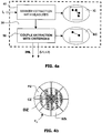
- the localizer detection sub-means 30 comprise marker extraction sub-means 40 which perform elementary measures for extracting candidates of markers and forming candidates of couples of markers.
- stents may have their own stent markers, which are located on their borders.
- the tip of the guide wire shown in the Figs 1a to 2b could also be considered as a single localizer for stenosis border detection during the procedure of tip placement.
- said tip which marks the extremity of the guide wire, also indicates whether the guide wire has passed the stenosis area or not.
- Such a procedure of tip placement is rather critical because of the artery narrowing. Therefore, the detection of the stenosis borders during said procedure may help the practitioner pass the guide wire correctly through the stenosis.
- Said tip may be detected using ridge enhancement filtering means followed by thresholding means and skeletonization means.
- the localizers are balloon markers.
- the marker extraction sub-means 40 comprise several elementary measure sub-means, which are intended to characterize the candidates of markers:
- First measure means 41 that select punctual dark zones contrasting on a brighter background: This measure is provided by filter means, denoted by F 0 .
- filter means denoted by F 0 .
- an appropriate filter comprises three circular concentric zones, including a central zone CZ, a dead zone DZ and a peripheral zone PZ.
- the filter F 0 is also divided into n sectoral zones SZ covering 360° and numbered 1 to n.
- a current sectoral zone Z k is numbered k with 1 ⁇ k ⁇ n.
- the first measure consists in scanning a current image of the sequence of images in order to look for a punctual dark zone. A punctual dark zone can be detected when said punctual dark zone is centered in the filter.
- the first measure is based on the estimation of contrast of intensity between the central zone CZ and the peripheral zone PZ. Said estimation of contrast may be carried out by estimating the difference of the average of intensities between the central zone CZ and peripheral zone PZ. This simple measure would conduct to a linear estimation of the contrast. In order to refine the result of this estimation, the first measure is actually carried out by calculating the minimum of the n averages of intensities determined in the n peripheral sectoral zones separately. These minimum values of intensities are denoted by:
- This measure I F0 is determined by scanning each pixel of the original image I 0 with the filter F 0 . It provides an enhanced image, denoted by IZ1, of punctual dark zones, denoted by Z, where all other structures have disappeared, with the exception of said punctual dark zones that are now candidates to constitute markers.
- Second measure means 42 comprising histogram means denoted by H: in this image IZ1, each pixel has a gray level. From the image IZ1, there is constructed an histogram, which represents the different numbers H of pixels corresponding to each gray level value G. To the right of the axis G in Fig. 5 , there are the high gray level values and to the left of the axis G the low gray level values are stated. For each gray level value G, the height H of the box represents the number of pixels to be found having said gray level value. Since the average size of a punctual dark zones Z is determined by the characteristics of the filter F 0 , it is possible to estimate the size of a punctual zone in pixels.
- a number of p.z (p times z) pixels that have the highest gray levels is searched.
- the histogram H permits of accumulating the number of pixels in adjacent boxes, starting from the right of the axis G, until the estimated number of p.z pixels is reached for the image, i.e. for z zones of p pixels each, while choosing the p.z pixels having the highest gray levels, i. e. the pixels in the boxes to the right of the G axis.
- the histogram H permits of determining a gray level G H , which yields the p.z pixels.
- Third measure means 43 comprising threshold means denoted by T 1 ; a first intensity threshold T1 is then applied to the image IZ1.
- the threshold T 1 is chosen equal to the previously determined gray level G H . That permits of selecting in the image IZ1 said number p.z of pixels having at least a gray level equal to G H . A new image is formed for which the intensities and the coordinates of the pixels are known, thus forming the image of points IZ2.
- Fourth measure means 44 which perform a connectivity analysis on pixels previously selected for the image IZ2, in order to connect pixels pertaining to a same punctual dark zone Z.
- the labeling means 44 provide a number of labeled punctual dark zones in a new image IZ3.
- Second threshold T 2 is applied, for example, to the intensities of the pixels of the image IZ3 of labeled zones and to the diameter of the zones in order to select the best labeled zones.
- T 2 equals a product of a given intensity and a given diameter, in order to select a number of remaining punctual zones having the highest intensities and the best shapes for constituting markers, thus yielding an image of markers IZ4.
- the table CT provides an image IC of the possible marker couples C1, C2,...
- the localizer detection sub-means 30 further comprise couple extraction sub-means 50 for extracting the best couple of markers based on criterions among which:
- a criterion of strength the strength of the best couple must be larger than the strength of the other couples.
- the strength of a given couple may be determined as the average of enhanced intensities yielded by the filter F 0 .
- a criterion of similarity the markers of the best couple must be very similar structures.
- the similarity of the markers of possible couples is determined. Once the punctual dark zones Z of p pixels are determined, their centroids are calculated. Small Regions Of Interest, denoted by ROI are defined around each centroid, as represented by white squares in Fig. 6b .
- For each possible couple correlation is calculated between the corresponding ROIs. Strong correlation is an indication that the two strongly correlated ROIs correspond to the markers of a couple of markers.
- a criterion of continuous track the markers of a couple are carried by a monorail, which is guided by a guide wire.
- the guide wire is more or less visible.
- it may be enhanced by a ridge filter. So, if the markers of a possible couple are situated on a track corresponding to a ridge joining them, this constitutes another indication that the two zones located at the extremities of the continuous track correspond to a couple of markers.
- Such a continuous track may be qualified by estimating the average ridgeness along the path joining the two zones.
- the measure of average ridgeness must provide a track that has a shape as close to the shape of a segment or of a parabola as possible.
- the detection of a continuous track connecting the couple of markers may be performed using a fast marching technique.
- This technique well known to those skilled in the art, first attributes a cost to the pixels located in a neighborhood of the couple of markers. Said cost is for instance inversely proportional to the above calculated ridgeness. Said technique also forms a path between both markers which minimizes a total cost in a graph made of the pixels of said neighborhood.
- said continuous track will be called an inter-marker line IML. It is to be noted that the guide wire is present on a large portion of the artery and that consequently the inter-marker line may be detected beyond the markers.
- a criterion of motion the markers in the coronary artery are moving rapidly with respect to the cardiac pulses. False alarms, that is dark punctual zones that pertain to the background, are moving much more slowly with the patient's breathing. In order to eliminate these possible false alarms, a temporal difference is formed between two successive images of the sequence. This difference provides a measure of temporal contrast. The measure of temporal contrast permits of detecting the dark punctual zones showing an important temporal contrast. This measure is also an indication of a possible couple of markers, since false alarms have a feebler temporal contrast.
- All described criterions are combined using a fuzzy logic technique for deriving a composite measure.
- the highest composite measure permits of selecting the best couple of markers from the image of couples IC issued by the marker extraction means 1.
- the coordinates of said markers denoted by (L 1 , L 2 ) in Fig. 4a and the coordinates of the pixels forming the inter-marker line IML are output.
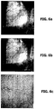
- Fig. 6a shows an original image of a medical sequence representing a catheter, a guide wire, a balloon with balloon markers (as two small dark points) and an artery on a background of other organs.
- the visualization of the objects of interest is very difficult. Even the balloon markers are hardly visible.
- Fig. 6b shows the original image with zones delimited in white, which are intended for the determination of the punctual dark zones.
- Fig. 6c the objects of interest are enhanced and the background is filtered.
- the localizers may be temporally registered during the visualization of the image sequence with respect to the frame of the image, by matching corresponding localizers of a current image and of a reference image in the sequence of images.
- the localizer registration allows further registering of the objects of interest, which practically do not move with respect to the localizers.
- the object of interest may be zoomed, as shown in Fig. 6c , without said object being shifted out of the image frame.
- temporal filtering means may be used in combination with the means of the invention to further improve the images of the sequence.
- Said image I 0 , said marker coordinates (L 1 , L 2 ) and said inter-marker line IML are then processed by the border detection sub-means 60 presented in Fig. 3 .
- Said border detection sub-means 60 aim at deriving the borders of the object of interest from the knowledge of the localizer's location (L 1 , L 2 ). In the preferred embodiment of the invention, this may for instance be carried out by an active contour technique (also called "snake").
- This technique well known to those skilled in the art, first of all consists in defining an initial contour and secondly in making said initial contour evolve under the influence of internal and external forces.
- said border detection sub-means 60 comprise initialization sub-means 61 and active contour sub-means 62 as shown in Fig. 3 .
- said initialization sub-means 61 may use the marker locations (L 1 , L 2 ) to derive an elliptical initial contour EIC defined by a major axis MA equal to a distance between markers L 1 and L 2 and called an inter-marker distance IMD and a minor axis mA equal to a percentage of said inter-marker distance IMD.
- a contour RIC of a rubber band RB having the inter-marker line as a medial axis Said initial contour EIC or RIC is then used as a starting position for an active contour AC, shown Fig. 8a , which is deformed by said active contour sub-means 62.
- a dynamic of the active contour AC is given by a law of motion. The deformation of said active contour AC implies two types of forces, which are applied at each point of the active contour AC on a normal to said contour:
- the inter-marker line IML has a non-negligible ridgeness due to the guide wire contrast. Said ridgeness may cause parasitic external forces that have to be eliminated, in order to prevent the active contour from being attracted by said inter-marker line IML. This is done easily since the location of said inter-marker line is well known.
- said active contour AC stops in a final position, which is the location of the borders BL of the object of interest as shown in Fig. 8b .
- the viewing system (as shown in Fig. 9 ) also comprises enhancement means 70 for enhancing said borders using said location of borders BL and for delivering an enhanced sequence of images EIS. Since said location of borders BL is known, the borders of the object of interest are enhanced very easily. Said borders are formed by points that have a gray level value. Said enhancement means 70 simply consist in increasing said gray level values so as to make the borders more visible. An outstanding enhancement is thus obtained and the main issue is to tune the enhancement so as to keep the enhanced sequence of images EIS acceptable for the practitioner.
- the viewing system (as shown Fig. 9 ) also comprises measurement means 71 for measuring characteristics CM of said object of interest using said location of borders BL.
- An interesting characteristic measure of a tubular object like a stent or an artery is a collection of widths of said object measured at several locations along a length of said object, for instance along said inter-marker line IML for a stent or along the tip for a stenosis. Variations of said widths may indicate whether the stenosis has been properly reduced or whether the stent has been properly expanded.
- the invention is not limited to width measures.
- the knowledge of the stent or of the artery borders also enables for instance an estimation of an agent contrast flow in the stenosis area to be derived, by measuring the mean contrast of contiguous sections of the artery at different times.
- the viewing system (as shown Fig. 9 ) also comprises 3D representation means 72 for delivering a three-dimensional (or 3D) representation 3DR of said object of interest using said location of borders BL.
- 3D representation means 72 for delivering a three-dimensional (or 3D) representation 3DR of said object of interest using said location of borders BL.
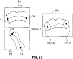
- Such a 3D representation of a tubular object of interest like an artery or a stent is easily obtained from two views (I 0 , I 0 '), which are preferably orthogonal views of said tubular object. It is not an issue in the domain of angiography, where an X-ray C-arm medical examination apparatus may provide two views in directions perpendicular to the axis of the tubular object and perpendicular to each other. It is also to be noted that very little distortion is introduced since the patient is placed at the center of the medical examination apparatus.
- the localizers (L 1 , L 2 , L' 1 , L' 2 ) detected in each sequence of images are matched and define a 3D referential in which all the points of the borders of the object of interest may be positioned in 3D. It is then possible to obtain 3D measurements of the object of interest and 3D visualizations. In particular, if the geometry of the object of interest is known or if a 3D model is available, it is possible to fit said model to the border points and object characteristics so as to obtain a realistic 3D viewing of the object of interest.
- a 3D model like a cylindrical shape with a circular or an elliptical section may be used for a 3D representation of a stent or an artery (as shown in Fig. 10 ).
- Said 3D representation may offer information about the stent placement or the stent bending for instance.
- a sequence of reference images also called peri-interventional images, is usually acquired before the intervention with an injection of a contrast agent, which makes arteries visible.
- Said sequence of reference images therefore, comprises features like the artery borders, which help the practitioner to locate and assess a stenosis before starting the procedure of stent placement.
- contrast agent is generally not injected and, consequently, the artery and stenosis borders are usually visible neither in the image sequence IS nor in the sequence of enhanced images EIS provided in real time by the viewing system according to the invention.
- a way of improving the accuracy of the visualization is to provide the practitioner with the features of the sequence of reference images during the procedure of stent placement.
- the viewing means therefore comprise local registration means 80 for registering said sequence of reference images or part of it with respect to said sequence of enhanced images EIS so as to form a new sequence of enhanced images, in which said sequence of reference images and said sequence of enhanced images are combined.
- the sequence of enhanced images EIS output by the enhancement means 70 is a live sequence, which will be denoted by EIS(t) hereinafter.
- the sequence of reference images RIS(n) is a stored sequence, comprising a number n of images. Referring to Fig. 11 , both sequences are entered in the local registration means 80.
- a reference image RIS(n 0 ) is registered using for instance a block-matching technique. Gray level values of said reference image RI are combined with the gray level values of the corresponding enhanced image EI(t 0 ) using for instance an ⁇ -blending technique. The correspondence between no and to can be evaluated through the compensation of the respiratory and heart motions.
- a new enhanced image NEI(t 0 ) is output, in which the features of the reference image RI(n 0 ), like the borders of the artery are seen through the enhanced image EI(t 0 ).
- sequence of enhanced images EIS(t) can as well be registered with respect to the sequence of reference images RIS(n) so as to provide a new sequence of reference images NRIS(n) (as shown in Fig. 11 ).
- enhanced features of an enhanced image EI(t 0 ) like the stent borders, are made visible through the corresponding reference image RI(n 0 ).
- Fig. 12 shows the basic components of an embodiment of an image viewing system 150 in accordance with the present invention, which is incorporated in a medical examination apparatus.
- said medical examination apparatus has acquisition means 151 for acquiring a sequence of images IS.
- Said sequence of images IS is processed by a processing device 153 comprising detection means as described above.
- the image viewing system 150 is generally used in the intervention room or near the intervention room for the processing of real time images. Should steps of the present method be applied to stored medical images, for example for estimating medical parameters, the system for processing the data of the stored images would be called an image viewing station.
- the medical examination apparatus provides the image data IS via a connection 157 to the processing device 153.
- Said processing system 153 provides processed image data to display and/or storage means.
- the display means 154 may be a screen.
- the storage means may be a memory MEM of the processing system 153.
- Said storage means may alternatively be external storage means.
- This processing device 153 may comprise a suitably programmed computer, or a special purpose processor having circuit means such as LUTs, Memories, Filters, Logic Operators, that are arranged to perform the functions of the steps of the method according to the invention.
- the image viewing system 150 may also comprise a keyboard 155 and a mouse 156. Icons may be provided on the screen to be activated by mouse clicks, or special pushbuttons may be provided on the system, to constitute control means 158 for the user to start, to control the duration or to stop the processing means of the system at selected instants.
- the present invention is not limited to two-dimensional image sequences.
- a volume of angiographic data comprising several views of a region of interest of the human body at a same time t, may be acquired by an X-ray C-arm medical examination apparatus.
- the described processing steps may be applied to each view produced at the time t.
- the present invention is applicable regardless of the medical imaging technology that is used to generate the initial data.
- Various modifications can be made to the order in which processing steps are performed in the described specific embodiment.
- the described processing steps applied to medical image data can advantageously be combined with various other known processing/visualization techniques.
Landscapes
- Engineering & Computer Science (AREA)
- Computer Vision & Pattern Recognition (AREA)
- Physics & Mathematics (AREA)
- General Physics & Mathematics (AREA)
- Theoretical Computer Science (AREA)
- Software Systems (AREA)
- Health & Medical Sciences (AREA)
- General Health & Medical Sciences (AREA)
- Medical Informatics (AREA)
- Nuclear Medicine, Radiotherapy & Molecular Imaging (AREA)
- Radiology & Medical Imaging (AREA)
- Quality & Reliability (AREA)
- Apparatus For Radiation Diagnosis (AREA)
- Image Analysis (AREA)
- Image Processing (AREA)
Claims (13)
- Ansichtsanordnung (150), umfassend Erfassungsmittel (151) zum Erfassen einer Bildsequenz (IS), Detektionsmitteln (20) zum Detektieren eines interessierenden Objekts (2, 17) in der genannten Bildsequenz (IS),
wobei die genannten Detektionsmittel (20) Folgendes umfassen:- Lokalisiererdetektions-Teilmittel (30) zum Detektieren eines Orts (L1, L2) von Lokalisierern in Bezug auf das genannte interessierende Objekt, wobei die Lokalisierer aus einem röntgendichtem Material bestehen,- Kantendetektions-Teilmittel (60) zum indirekten Detektieren eines Orts von Kanten (BL) in Bezug auf das genannte interessierende Objekt unter Verwendung des genannten Orts von Lokalisierern,und Ansichtsmittel (154) zum Anzeigen der genannten Bildsequenz (IS);
wobei die genannten Kantendetektions-Teilmittel (60) Folgendes umfassen:- Initialisierungs-Teilmittel (61) zum Erstellen einer anfänglichen Kontur (EIC, RIC) der genannten Kanten, enthaltend die genannte Lokalisierer (L1, L2), die sich innerhalb oder außerhalb des interessierenden Objekts befinden, anhand von a-priori-Kenntnissen über das genannte interessierende Objekt,- aktive Kontur-Teilmittel (62) zum Bewegen der genannten anfänglichen Kontur (EIC, RIC) unter der Wirkung von Kräften in Bezug auf das genannte interessierende Objekt (2, 17) innerhalb der genannten Bildsequenz (IS),wobei die genannten Lokalisiererdetektions-Teilmittel (30) weiterhin Folgendes umfassen:Markierungsextraktions-Teilmittel (40), die elementare Messungen durchführen, um Kandidaten für Markierungen zu extrahieren und Kandidaten für Markierungspaare zu bilden, undPaarextraktions-Teilmittel (50) zum Extrahieren des besten Markierungspaars. - Ansichtsanordnung (150) nach Anspruch 1, umfassend Verbesserungsmittel (70) zum Verbessern der genannten Kanten unter Verwendung des genannten Orts von Kanten (BL) und zum Bereitstellen einer verbesserten Bildsequenz (EIS).
- Ansichtsanordnung (150) nach Anspruch 1, umfassend Messmittel (71) zum Messen von Eigenschaften (CM) des genannten interessierenden Objekts unter Verwendung des genannten Orts von Kanten (BL).
- Ansichtsanordnung (150) nach Anspruch 3, wobei die genannten Eigenschaften (CM) Breiten des genannten interessierenden Objekts entlang einer Länge des genannten interessierenden Objekts sind.
- Ansichtsanordnung nach Anspruch 1, wobei die genannten Erfassungsmittel (151) in der Lage sind, mindestens zwei Ansichten des genannten interessierenden Objekts zu erfassen, wobei die genannte Ansichtsanordnung auch 3D-Darstellungsmittel (72) zum Bereitstellen einer 3D-Darstellung (3DR) des genannten interessierenden Objekts anhand der genannten Ansichten und des genannten Orts von Kanten (BL) umfassen.
- Ansichtsanordnung nach Anspruch 5, wobei ein zylindrisches Modell durch die genannten 3D-Darstellungsmittel (72) verwendet wird, wenn das genannte interessierende Objekt röhrenförmig ist.
- Ansichtsanordnung nach einem der Ansprüche 1 bis 6, wobei das genannte interessierende Objekt eine Stenose (2) oder ein Stent (17) ist und die genannten Lokalisierer eine Spitze (9) oder Ballonmarkierungen (13, 14) sind.
- Ansichtsanordnung nach Anspruch 2, wobei die genannten Ansichtsmittel (154) auch lokale Registrierungsmittel (80) zum Registrieren einer Sequenz von Referenzbildern (RIS(n)) in Bezug auf die genannte Sequenz von verbesserten Bildern (EIS, EIS(t)) umfasst, um eine neue Sequenz von verbesserten Bildern (NEIS(t)) zu bilden, in der die genannte Sequenz von verbesserten Bildern und die genannte Sequenz von Referenzbildern kombiniert werden,
wobei die Sequenz von Referenzbildern (RIS(n)) vor einem Eingriff mit einer Injektion von Kontrastmittel erfasst wird. - Ansichtsanordnung nach Anspruch 2, wobei die genannten Ansichtsmittel (154) auch lokale Registrierungsmittel (80) zum Registrieren der genannten Sequenz von verbesserten Bildern (EIS, EIS(t)) in Bezug auf eine Sequenz von Referenzbildern (RIS(n)) umfassen, um eine neue Sequenz von Referenzbildern (NRIS(n)) zu bilden, in der die genannte Sequenz von verbesserten Bildern und die genannte Sequenz von Referenzbildern kombiniert werden.
- Verfahren, umfassend einen Detektionsschritt (20) zum Detektieren eines interessierenden Objekts in einer Bildsequenz (IS), wobei der genannte Detektionsschritt die folgenden Teilschritte umfasst:- Lokalisiererdetektion (30) zum Detektieren eines Orts von Lokalisierern (L1, L2) in Bezug auf das genannte interessierende Objekt, wobei die Lokalisierer aus einem röntgendichtem Material bestehen, wobei der Lokalisererdetektionsschritt weiterhin a) das Durchführen von elementaren Messungen zum Extrahieren von Kandidaten für Markierungen, b) das Bilden von Kandidaten von Markierungspaaren und c) das Extrahieren des besten Markierungspaars umfasst,- Kantendetektion (60) zum indirekten Detektieren eines Orts von Kanten (BL) in Bezug auf das genannte interessierende Objekt unter Verwendung des genannten Orts von Lokalisierern,- Erstellen einer anfänglichen Kontur (EIC, RIC) der genannten Kanten, enthaltend die genannte Lokalisierer (L1, L2), die sich innerhalb oder außerhalb des interessierenden Objekts befinden, anhand von a-priori-Kenntnissen über das genannte interessierende Objekt, unter Verwendung von Initialisierungs-Teilmitteln (61),- Bewegen der genannten anfänglichen Kontur (EIC, RIC) unter der Wirkung von Kräften in Bezug auf das genannte interessierende Objekt (2, 17) innerhalb der genannten Bildsequenz (IS) unter Verwendung von aktiven Kontur-Teilmitteln (62).
- Vorrichtung (153) umfassend Detektionsmittel (20) zum Detektieren eines interessierenden Objekts in einer Bildsequenz (IS), wobei die genannten Detektionsmittel Folgendes umfassen:- Lokalisiererdetektions-Teilmittel (30) zum Detektieren eines Orts von Lokalisierern in Bezug auf das genannte interessierende Objekt,- Kantendetektions-Teilmittel (60) zum indirekten Detektieren eines Orts von Kanten (BL) in Bezug auf das genannte interessierende Objekt unter Verwendung des genannten Orts von Lokalisierern,wobei die genannten Kantendetektions-Teilmittel (60) Folgendes umfassen:- Initialisierungs-Teilmittel (61) zum Erstellen einer anfänglichen Kontur (EIC, RIC) der genannten Kanten, enthaltend die genannten Lokalisierer (L1, L2), die sich innerhalb oder außerhalb des interessierenden Objekts befinden, anhand von a-priori-Kenntnissen über das genannte interessierende Objekt,- aktive Kontur-Teilmittel (62) zum Bewegen der genannten anfänglichen Kontur (EIC, RIC) unter der Wirkung von Kräften in Bezug auf das genannte interessierende Objekt (2, 17) innerhalb der genannten Bildsequenz (IS),wobei die genannten Lokalisiererdetektions-Teilmittel (30) Folgendes umfassen:Markierungsextraktions-Teilmittel (40), die elementare Messungen durchführen, um Kandidaten für Markierungen zu extrahieren und Kandidaten für Markierungspaare zu bilden, undPaarextraktions-Teilmittel (50) zum Extrahieren des besten Markierungspaars.
- Computerprogramm umfassend einen Satz von Anweisungen zum Implementieren eines Verfahrens nach Anspruch 10, wenn das genannte Programm durch einen Prozessor ausgeführt wird.
- Medizinisches Untersuchungsbildgebungsgerät umfassend eine Ansichtsanordnung (150) nach einem der Ansprüche 1 bis 9.
Priority Applications (1)
| Application Number | Priority Date | Filing Date | Title |
|---|---|---|---|
| EP03772579.3A EP1570432B1 (de) | 2002-12-04 | 2003-11-26 | Medizinische darstellungsanordnung, und verfahren zur detektion der kanten eines interessierenden objekts in verrauschten bildern |
Applications Claiming Priority (6)
| Application Number | Priority Date | Filing Date | Title |
|---|---|---|---|
| EP02292995 | 2002-12-04 | ||
| EP02292995 | 2002-12-04 | ||
| EP03290455 | 2003-02-26 | ||
| EP03290455 | 2003-02-26 | ||
| PCT/IB2003/005495 WO2004051572A2 (en) | 2002-12-04 | 2003-11-26 | Medical viewing system and method for detecting borders of an object of interest in noisy images |
| EP03772579.3A EP1570432B1 (de) | 2002-12-04 | 2003-11-26 | Medizinische darstellungsanordnung, und verfahren zur detektion der kanten eines interessierenden objekts in verrauschten bildern |
Publications (2)
| Publication Number | Publication Date |
|---|---|
| EP1570432A2 EP1570432A2 (de) | 2005-09-07 |
| EP1570432B1 true EP1570432B1 (de) | 2017-03-22 |
Family
ID=32471908
Family Applications (1)
| Application Number | Title | Priority Date | Filing Date |
|---|---|---|---|
| EP03772579.3A Expired - Lifetime EP1570432B1 (de) | 2002-12-04 | 2003-11-26 | Medizinische darstellungsanordnung, und verfahren zur detektion der kanten eines interessierenden objekts in verrauschten bildern |
Country Status (5)
| Country | Link |
|---|---|
| US (1) | US7551758B2 (de) |
| EP (1) | EP1570432B1 (de) |
| JP (1) | JP4714468B2 (de) |
| AU (1) | AU2003279472A1 (de) |
| WO (1) | WO2004051572A2 (de) |
Families Citing this family (42)
| Publication number | Priority date | Publication date | Assignee | Title |
|---|---|---|---|---|
| US20060063973A1 (en) | 2004-04-21 | 2006-03-23 | Acclarent, Inc. | Methods and apparatus for treating disorders of the ear, nose and throat |
| US20190314620A1 (en) | 2004-04-21 | 2019-10-17 | Acclarent, Inc. | Apparatus and methods for dilating and modifying ostia of paranasal sinuses and other intranasal or paranasal structures |
| US8894614B2 (en) | 2004-04-21 | 2014-11-25 | Acclarent, Inc. | Devices, systems and methods useable for treating frontal sinusitis |
| US20070208252A1 (en) * | 2004-04-21 | 2007-09-06 | Acclarent, Inc. | Systems and methods for performing image guided procedures within the ear, nose, throat and paranasal sinuses |
| US7803150B2 (en) | 2004-04-21 | 2010-09-28 | Acclarent, Inc. | Devices, systems and methods useable for treating sinusitis |
| US10188413B1 (en) | 2004-04-21 | 2019-01-29 | Acclarent, Inc. | Deflectable guide catheters and related methods |
| US8747389B2 (en) | 2004-04-21 | 2014-06-10 | Acclarent, Inc. | Systems for treating disorders of the ear, nose and throat |
| US9399121B2 (en) | 2004-04-21 | 2016-07-26 | Acclarent, Inc. | Systems and methods for transnasal dilation of passageways in the ear, nose or throat |
| US7654997B2 (en) | 2004-04-21 | 2010-02-02 | Acclarent, Inc. | Devices, systems and methods for diagnosing and treating sinusitus and other disorders of the ears, nose and/or throat |
| US20070167682A1 (en) | 2004-04-21 | 2007-07-19 | Acclarent, Inc. | Endoscopic methods and devices for transnasal procedures |
| US8702626B1 (en) | 2004-04-21 | 2014-04-22 | Acclarent, Inc. | Guidewires for performing image guided procedures |
| WO2006056924A1 (en) * | 2004-11-24 | 2006-06-01 | Koninklijke Philips Electronics N.V. | Multi-feature time filtering for enhancing structures in noisy images |
| JP5068670B2 (ja) * | 2005-02-10 | 2012-11-07 | コーニンクレッカ フィリップス エレクトロニクス エヌ ヴィ | 画像処理装置及び方法 |
| US20060239527A1 (en) * | 2005-04-25 | 2006-10-26 | Sriram Krishnan | Three-dimensional cardiac border delineation in medical imaging |
| US8951225B2 (en) | 2005-06-10 | 2015-02-10 | Acclarent, Inc. | Catheters with non-removable guide members useable for treatment of sinusitis |
| JP2009515635A (ja) * | 2005-11-18 | 2009-04-16 | コーニンクレッカ フィリップス エレクトロニクス エヌ ヴィ | 三次元画像における所定の構造の描画方法 |
| EP2104921B1 (de) | 2006-11-28 | 2018-07-11 | Koninklijke Philips N.V. | Verfahren, vorrichtung und computerprogamm zur datenverarbeitung |
| DE102006058605A1 (de) * | 2006-12-11 | 2008-06-19 | Siemens Ag | Bildakquisitions- und Bildverarbeitungssystem mit zugehörigem Verfahren zur Rekonstruktion des bewegungsbedingten Verkippungs- und Verkrümmungszustands abgebildeter Gefäßimplantate in Angiokardiogrammen |
| WO2008083857A1 (en) * | 2007-01-10 | 2008-07-17 | Nobel Biocare Services Ag | Method and system for dental planning and production |
| EP2129293B1 (de) * | 2007-02-27 | 2018-10-10 | Koninklijke Philips N.V. | Vorrichtung zur aufzeichnung einer gefässstruktur während eines eingriffs |
| DE102007019328A1 (de) | 2007-04-24 | 2008-11-06 | Siemens Ag | Verfahren zur hochauflösenden Darstellung filigraner Gefäßimplantate in angiographischen Aufnahmen |
| CN101939764A (zh) * | 2007-09-21 | 2011-01-05 | 皇家飞利浦电子股份有限公司 | 利用双扭曲增强移动结构的方法 |
| US8275201B2 (en) * | 2008-03-06 | 2012-09-25 | Tyco Healthcare Group Lp | Image enhancement and application functionality for medical and other uses |
| RU2506056C2 (ru) | 2008-09-18 | 2014-02-10 | Аккларент, Инк. | Способы и аппарат для лечения заболеваний уха, горла, носа |
| JP5523785B2 (ja) * | 2008-10-07 | 2014-06-18 | 株式会社東芝 | 3次元画像処理装置 |
| JP5523791B2 (ja) | 2008-10-27 | 2014-06-18 | 株式会社東芝 | X線診断装置および画像処理装置 |
| EP2408375B1 (de) | 2009-03-20 | 2017-12-06 | Orthoscan Incorporated | Bewegliche bildgebungsvorrichtung |
| US8457374B2 (en) | 2009-06-22 | 2013-06-04 | Siemens Medical Solutions Usa, Inc. | System for detecting catheterization devices |
| US8655042B2 (en) * | 2009-06-23 | 2014-02-18 | Koninklijke Philips N.V. | Device sizing support during interventions |
| CN102598053A (zh) * | 2009-06-24 | 2012-07-18 | 皇家飞利浦电子股份有限公司 | 对象内的植入设备的空间和形状表征 |
| US8718338B2 (en) * | 2009-07-23 | 2014-05-06 | General Electric Company | System and method to compensate for respiratory motion in acquired radiography images |
| US9125611B2 (en) | 2010-12-13 | 2015-09-08 | Orthoscan, Inc. | Mobile fluoroscopic imaging system |
| KR101885774B1 (ko) * | 2011-12-27 | 2018-09-11 | 삼성전자주식회사 | 방사선 영상 처리 방법 및 그에 따른 방사선 영상 처리 장치 |
| WO2013133288A1 (ja) * | 2012-03-06 | 2013-09-12 | 株式会社東芝 | 画像処理装置、x線撮影装置及び画像処理方法 |
| US9053551B2 (en) | 2012-05-23 | 2015-06-09 | International Business Machines Corporation | Vessel identification using shape and motion mapping for coronary angiogram sequences |
| WO2015155770A1 (en) * | 2014-04-10 | 2015-10-15 | Sync-Rx, Ltd. | Image analysis in the presence of a medical device |
| JP2016019724A (ja) | 2014-06-19 | 2016-02-04 | 株式会社東芝 | X線診断装置 |
| US10631754B2 (en) * | 2016-05-16 | 2020-04-28 | Lightlab Imaging, Inc. | Intravascular absorbable stent detection and diagnostic methods and systems |
| RU2738014C1 (ru) * | 2017-07-18 | 2020-12-07 | Кефалиос С.А.С. | Регулируемые чрескожные устройства для аннулопластики, доставляющие системы, способ чрескожного развертывания устройства для аннулопластики и способ, осуществляемый с помощью одного или более обрабатывающих устройств |
| EP3522116A1 (de) * | 2018-01-31 | 2019-08-07 | Koninklijke Philips N.V. | Vorrichtung, system und verfahren zur positionsbestimmung von stents in einem bild einer gefässstruktur |
| US11087453B2 (en) * | 2018-06-11 | 2021-08-10 | Dynatek Labs, Inc. | Automated failure detection for medical device testing systems and methods |
| US12290401B2 (en) | 2020-03-05 | 2025-05-06 | Koninklijke Philips N.V. | Handheld ultrasound scanner with display retention and associated devices, systems, and methods |
Family Cites Families (6)
| Publication number | Priority date | Publication date | Assignee | Title |
|---|---|---|---|---|
| EP0723786A1 (de) * | 1995-01-30 | 1996-07-31 | Cardiovascular Concepts, Inc. | Katheter und Methode zur Abmessung von Läsionen |
| US7194117B2 (en) * | 1999-06-29 | 2007-03-20 | The Research Foundation Of State University Of New York | System and method for performing a three-dimensional virtual examination of objects, such as internal organs |
| US6148095A (en) * | 1997-09-08 | 2000-11-14 | University Of Iowa Research Foundation | Apparatus and method for determining three-dimensional representations of tortuous vessels |
| JP4095197B2 (ja) * | 1999-03-31 | 2008-06-04 | テルモ株式会社 | 管腔内留置物 |
| US6532380B1 (en) * | 2000-06-30 | 2003-03-11 | Cedars Sinai Medical Center | Image guidance for coronary stent deployment |
| US7397935B2 (en) * | 2004-05-10 | 2008-07-08 | Mediguide Ltd. | Method for segmentation of IVUS image sequences |
-
2003
- 2003-11-26 US US10/537,208 patent/US7551758B2/en not_active Expired - Fee Related
- 2003-11-26 JP JP2004570711A patent/JP4714468B2/ja not_active Expired - Fee Related
- 2003-11-26 WO PCT/IB2003/005495 patent/WO2004051572A2/en not_active Ceased
- 2003-11-26 AU AU2003279472A patent/AU2003279472A1/en not_active Abandoned
- 2003-11-26 EP EP03772579.3A patent/EP1570432B1/de not_active Expired - Lifetime
Non-Patent Citations (1)
| Title |
|---|
| None * |
Also Published As
| Publication number | Publication date |
|---|---|
| US7551758B2 (en) | 2009-06-23 |
| JP4714468B2 (ja) | 2011-06-29 |
| AU2003279472A1 (en) | 2004-06-23 |
| WO2004051572A2 (en) | 2004-06-17 |
| US20060155184A1 (en) | 2006-07-13 |
| WO2004051572A3 (en) | 2004-11-04 |
| EP1570432A2 (de) | 2005-09-07 |
| JP2006508772A (ja) | 2006-03-16 |
Similar Documents
| Publication | Publication Date | Title |
|---|---|---|
| US7551758B2 (en) | Medical viewing system and method for detecting borders of an object of interest in noisy images | |
| EP1459257B1 (de) | Medizinisches darstellungssystem und verfahren zur räumlichen verbesserung von strukturen in verrauschten bildern | |
| US7289652B2 (en) | Medical viewing system and method for detecting and enhancing structures in noisy images | |
| JP4988557B2 (ja) | Ptca血管造影図の制御に対するビューイング装置 | |
| US7991453B2 (en) | Medical viewing system and method for detecting boundary structures | |
| EP1817743B1 (de) | Zeitfilterung mit mehreren eigenschaften zur strukturverbesserung bei verrauschten bildern | |
| US7877132B2 (en) | Medical viewing system and method for detecting and enhancing static structures in noisy images using motion of the image acquisition means | |
| JP4426297B2 (ja) | ノイズの多い画像中の構造を強調する医用ビューイングシステム及び方法 | |
| US20110033094A1 (en) | Method and apparatus for navigating a therapeutic device to a location | |
| US20080275335A1 (en) | Methods and apparatus for virtual coronary mapping | |
| US7620221B2 (en) | System and method for enhancing an object of interest in noisy medical images |
Legal Events
| Date | Code | Title | Description |
|---|---|---|---|
| PUAI | Public reference made under article 153(3) epc to a published international application that has entered the european phase |
Free format text: ORIGINAL CODE: 0009012 |
|
| 17P | Request for examination filed |
Effective date: 20050704 |
|
| AK | Designated contracting states |
Kind code of ref document: A2 Designated state(s): AT BE BG CH CY CZ DE DK EE ES FI FR GB GR HU IE IT LI LU MC NL PT RO SE SI SK TR |
|
| AX | Request for extension of the european patent |
Extension state: AL LT LV MK |
|
| DAX | Request for extension of the european patent (deleted) | ||
| RAP1 | Party data changed (applicant data changed or rights of an application transferred) |
Owner name: KONINKLIJKE PHILIPS N.V. |
|
| GRAP | Despatch of communication of intention to grant a patent |
Free format text: ORIGINAL CODE: EPIDOSNIGR1 |
|
| GRAJ | Information related to disapproval of communication of intention to grant by the applicant or resumption of examination proceedings by the epo deleted |
Free format text: ORIGINAL CODE: EPIDOSDIGR1 |
|
| GRAP | Despatch of communication of intention to grant a patent |
Free format text: ORIGINAL CODE: EPIDOSNIGR1 |
|
| INTG | Intention to grant announced |
Effective date: 20160422 |
|
| INTG | Intention to grant announced |
Effective date: 20160510 |
|
| GRAJ | Information related to disapproval of communication of intention to grant by the applicant or resumption of examination proceedings by the epo deleted |
Free format text: ORIGINAL CODE: EPIDOSDIGR1 |
|
| GRAS | Grant fee paid |
Free format text: ORIGINAL CODE: EPIDOSNIGR3 |
|
| GRAP | Despatch of communication of intention to grant a patent |
Free format text: ORIGINAL CODE: EPIDOSNIGR1 |
|
| INTC | Intention to grant announced (deleted) | ||
| INTG | Intention to grant announced |
Effective date: 20161013 |
|
| GRAJ | Information related to disapproval of communication of intention to grant by the applicant or resumption of examination proceedings by the epo deleted |
Free format text: ORIGINAL CODE: EPIDOSDIGR1 |
|
| STAA | Information on the status of an ep patent application or granted ep patent |
Free format text: STATUS: EXAMINATION IS IN PROGRESS |
|
| GRAJ | Information related to disapproval of communication of intention to grant by the applicant or resumption of examination proceedings by the epo deleted |
Free format text: ORIGINAL CODE: EPIDOSDIGR1 |
|
| GRAP | Despatch of communication of intention to grant a patent |
Free format text: ORIGINAL CODE: EPIDOSNIGR1 |
|
| GRAS | Grant fee paid |
Free format text: ORIGINAL CODE: EPIDOSNIGR3 |
|
| STAA | Information on the status of an ep patent application or granted ep patent |
Free format text: STATUS: GRANT OF PATENT IS INTENDED |
|
| GRAA | (expected) grant |
Free format text: ORIGINAL CODE: 0009210 |
|
| STAA | Information on the status of an ep patent application or granted ep patent |
Free format text: STATUS: THE PATENT HAS BEEN GRANTED |
|
| AK | Designated contracting states |
Kind code of ref document: B1 Designated state(s): AT BE BG CH CY CZ DE DK EE ES FI FR GB GR HU IE IT LI LU MC NL PT RO SE SI SK TR |
|
| INTG | Intention to grant announced |
Effective date: 20161013 |
|
| REG | Reference to a national code |
Ref country code: GB Ref legal event code: FG4D |
|
| REG | Reference to a national code |
Ref country code: CH Ref legal event code: EP |
|
| REG | Reference to a national code |
Ref country code: AT Ref legal event code: REF Ref document number: 878443 Country of ref document: AT Kind code of ref document: T Effective date: 20170415 |
|
| REG | Reference to a national code |
Ref country code: IE Ref legal event code: FG4D |
|
| REG | Reference to a national code |
Ref country code: DE Ref legal event code: R096 Ref document number: 60350043 Country of ref document: DE |
|
| REG | Reference to a national code |
Ref country code: NL Ref legal event code: MP Effective date: 20170322 |
|
| PG25 | Lapsed in a contracting state [announced via postgrant information from national office to epo] |
Ref country code: GR Free format text: LAPSE BECAUSE OF FAILURE TO SUBMIT A TRANSLATION OF THE DESCRIPTION OR TO PAY THE FEE WITHIN THE PRESCRIBED TIME-LIMIT Effective date: 20170623 Ref country code: FI Free format text: LAPSE BECAUSE OF FAILURE TO SUBMIT A TRANSLATION OF THE DESCRIPTION OR TO PAY THE FEE WITHIN THE PRESCRIBED TIME-LIMIT Effective date: 20170322 |
|
| REG | Reference to a national code |
Ref country code: AT Ref legal event code: MK05 Ref document number: 878443 Country of ref document: AT Kind code of ref document: T Effective date: 20170322 |
|
| PG25 | Lapsed in a contracting state [announced via postgrant information from national office to epo] |
Ref country code: BG Free format text: LAPSE BECAUSE OF FAILURE TO SUBMIT A TRANSLATION OF THE DESCRIPTION OR TO PAY THE FEE WITHIN THE PRESCRIBED TIME-LIMIT Effective date: 20170622 Ref country code: SE Free format text: LAPSE BECAUSE OF FAILURE TO SUBMIT A TRANSLATION OF THE DESCRIPTION OR TO PAY THE FEE WITHIN THE PRESCRIBED TIME-LIMIT Effective date: 20170322 |
|
| PG25 | Lapsed in a contracting state [announced via postgrant information from national office to epo] |
Ref country code: NL Free format text: LAPSE BECAUSE OF FAILURE TO SUBMIT A TRANSLATION OF THE DESCRIPTION OR TO PAY THE FEE WITHIN THE PRESCRIBED TIME-LIMIT Effective date: 20170322 |
|
| PG25 | Lapsed in a contracting state [announced via postgrant information from national office to epo] |
Ref country code: RO Free format text: LAPSE BECAUSE OF FAILURE TO SUBMIT A TRANSLATION OF THE DESCRIPTION OR TO PAY THE FEE WITHIN THE PRESCRIBED TIME-LIMIT Effective date: 20170322 Ref country code: EE Free format text: LAPSE BECAUSE OF FAILURE TO SUBMIT A TRANSLATION OF THE DESCRIPTION OR TO PAY THE FEE WITHIN THE PRESCRIBED TIME-LIMIT Effective date: 20170322 Ref country code: IT Free format text: LAPSE BECAUSE OF FAILURE TO SUBMIT A TRANSLATION OF THE DESCRIPTION OR TO PAY THE FEE WITHIN THE PRESCRIBED TIME-LIMIT Effective date: 20170322 Ref country code: AT Free format text: LAPSE BECAUSE OF FAILURE TO SUBMIT A TRANSLATION OF THE DESCRIPTION OR TO PAY THE FEE WITHIN THE PRESCRIBED TIME-LIMIT Effective date: 20170322 Ref country code: SK Free format text: LAPSE BECAUSE OF FAILURE TO SUBMIT A TRANSLATION OF THE DESCRIPTION OR TO PAY THE FEE WITHIN THE PRESCRIBED TIME-LIMIT Effective date: 20170322 Ref country code: ES Free format text: LAPSE BECAUSE OF FAILURE TO SUBMIT A TRANSLATION OF THE DESCRIPTION OR TO PAY THE FEE WITHIN THE PRESCRIBED TIME-LIMIT Effective date: 20170322 Ref country code: CZ Free format text: LAPSE BECAUSE OF FAILURE TO SUBMIT A TRANSLATION OF THE DESCRIPTION OR TO PAY THE FEE WITHIN THE PRESCRIBED TIME-LIMIT Effective date: 20170322 |
|
| REG | Reference to a national code |
Ref country code: FR Ref legal event code: PLFP Year of fee payment: 15 |
|
| PG25 | Lapsed in a contracting state [announced via postgrant information from national office to epo] |
Ref country code: PT Free format text: LAPSE BECAUSE OF FAILURE TO SUBMIT A TRANSLATION OF THE DESCRIPTION OR TO PAY THE FEE WITHIN THE PRESCRIBED TIME-LIMIT Effective date: 20170724 |
|
| REG | Reference to a national code |
Ref country code: DE Ref legal event code: R097 Ref document number: 60350043 Country of ref document: DE |
|
| PLBE | No opposition filed within time limit |
Free format text: ORIGINAL CODE: 0009261 |
|
| STAA | Information on the status of an ep patent application or granted ep patent |
Free format text: STATUS: NO OPPOSITION FILED WITHIN TIME LIMIT |
|
| PG25 | Lapsed in a contracting state [announced via postgrant information from national office to epo] |
Ref country code: DK Free format text: LAPSE BECAUSE OF FAILURE TO SUBMIT A TRANSLATION OF THE DESCRIPTION OR TO PAY THE FEE WITHIN THE PRESCRIBED TIME-LIMIT Effective date: 20170322 |
|
| PGFP | Annual fee paid to national office [announced via postgrant information from national office to epo] |
Ref country code: FR Payment date: 20171127 Year of fee payment: 15 |
|
| 26N | No opposition filed |
Effective date: 20180102 |
|
| PG25 | Lapsed in a contracting state [announced via postgrant information from national office to epo] |
Ref country code: SI Free format text: LAPSE BECAUSE OF FAILURE TO SUBMIT A TRANSLATION OF THE DESCRIPTION OR TO PAY THE FEE WITHIN THE PRESCRIBED TIME-LIMIT Effective date: 20170322 |
|
| REG | Reference to a national code |
Ref country code: DE Ref legal event code: R119 Ref document number: 60350043 Country of ref document: DE |
|
| PG25 | Lapsed in a contracting state [announced via postgrant information from national office to epo] |
Ref country code: MC Free format text: LAPSE BECAUSE OF FAILURE TO SUBMIT A TRANSLATION OF THE DESCRIPTION OR TO PAY THE FEE WITHIN THE PRESCRIBED TIME-LIMIT Effective date: 20170322 |
|
| GBPC | Gb: european patent ceased through non-payment of renewal fee |
Effective date: 20171126 |
|
| PG25 | Lapsed in a contracting state [announced via postgrant information from national office to epo] |
Ref country code: LI Free format text: LAPSE BECAUSE OF NON-PAYMENT OF DUE FEES Effective date: 20171130 Ref country code: CH Free format text: LAPSE BECAUSE OF NON-PAYMENT OF DUE FEES Effective date: 20171130 |
|
| PG25 | Lapsed in a contracting state [announced via postgrant information from national office to epo] |
Ref country code: LU Free format text: LAPSE BECAUSE OF NON-PAYMENT OF DUE FEES Effective date: 20171126 |
|
| REG | Reference to a national code |
Ref country code: BE Ref legal event code: MM Effective date: 20171130 |
|
| REG | Reference to a national code |
Ref country code: IE Ref legal event code: MM4A |
|
| PG25 | Lapsed in a contracting state [announced via postgrant information from national office to epo] |
Ref country code: IE Free format text: LAPSE BECAUSE OF NON-PAYMENT OF DUE FEES Effective date: 20171126 Ref country code: DE Free format text: LAPSE BECAUSE OF NON-PAYMENT OF DUE FEES Effective date: 20180602 |
|
| PG25 | Lapsed in a contracting state [announced via postgrant information from national office to epo] |
Ref country code: GB Free format text: LAPSE BECAUSE OF NON-PAYMENT OF DUE FEES Effective date: 20171126 Ref country code: BE Free format text: LAPSE BECAUSE OF NON-PAYMENT OF DUE FEES Effective date: 20171130 |
|
| PG25 | Lapsed in a contracting state [announced via postgrant information from national office to epo] |
Ref country code: HU Free format text: LAPSE BECAUSE OF FAILURE TO SUBMIT A TRANSLATION OF THE DESCRIPTION OR TO PAY THE FEE WITHIN THE PRESCRIBED TIME-LIMIT; INVALID AB INITIO Effective date: 20031126 |
|
| PG25 | Lapsed in a contracting state [announced via postgrant information from national office to epo] |
Ref country code: FR Free format text: LAPSE BECAUSE OF NON-PAYMENT OF DUE FEES Effective date: 20181130 Ref country code: CY Free format text: LAPSE BECAUSE OF NON-PAYMENT OF DUE FEES Effective date: 20170322 |
|
| PG25 | Lapsed in a contracting state [announced via postgrant information from national office to epo] |
Ref country code: TR Free format text: LAPSE BECAUSE OF FAILURE TO SUBMIT A TRANSLATION OF THE DESCRIPTION OR TO PAY THE FEE WITHIN THE PRESCRIBED TIME-LIMIT Effective date: 20170322 |