EP1570422B1 - Layer arrangement provided with a structure producing a diffractive optical effect and a lens-type effect - Google Patents
Layer arrangement provided with a structure producing a diffractive optical effect and a lens-type effect Download PDFInfo
- Publication number
- EP1570422B1 EP1570422B1 EP03775318A EP03775318A EP1570422B1 EP 1570422 B1 EP1570422 B1 EP 1570422B1 EP 03775318 A EP03775318 A EP 03775318A EP 03775318 A EP03775318 A EP 03775318A EP 1570422 B1 EP1570422 B1 EP 1570422B1
- Authority
- EP
- European Patent Office
- Prior art keywords
- lens
- layer arrangement
- layer
- arrangement according
- grating
- Prior art date
- Legal status (The legal status is an assumption and is not a legal conclusion. Google has not performed a legal analysis and makes no representation as to the accuracy of the status listed.)
- Expired - Lifetime
Links
- 230000000694 effects Effects 0.000 title claims abstract description 32
- 230000003287 optical effect Effects 0.000 title claims description 10
- 239000000463 material Substances 0.000 claims description 8
- 238000010030 laminating Methods 0.000 claims description 6
- 239000002184 metal Substances 0.000 claims description 3
- 230000009467 reduction Effects 0.000 claims description 2
- 239000000049 pigment Substances 0.000 claims 1
- 229920003002 synthetic resin Polymers 0.000 abstract description 2
- 239000000057 synthetic resin Substances 0.000 abstract description 2
- 241000219739 Lens Species 0.000 description 83
- 239000010410 layer Substances 0.000 description 64
- 239000010408 film Substances 0.000 description 7
- 230000008901 benefit Effects 0.000 description 6
- 239000011888 foil Substances 0.000 description 6
- 238000000034 method Methods 0.000 description 6
- 230000005540 biological transmission Effects 0.000 description 5
- 239000004922 lacquer Substances 0.000 description 5
- 238000004519 manufacturing process Methods 0.000 description 5
- 239000000758 substrate Substances 0.000 description 4
- 240000004322 Lens culinaris Species 0.000 description 3
- 238000001465 metallisation Methods 0.000 description 3
- 239000004065 semiconductor Substances 0.000 description 3
- 230000000007 visual effect Effects 0.000 description 3
- 239000012790 adhesive layer Substances 0.000 description 2
- 239000003570 air Substances 0.000 description 2
- 230000008859 change Effects 0.000 description 2
- 239000003795 chemical substances by application Substances 0.000 description 2
- 239000011248 coating agent Substances 0.000 description 2
- 238000000576 coating method Methods 0.000 description 2
- 238000000609 electron-beam lithography Methods 0.000 description 2
- 238000004049 embossing Methods 0.000 description 2
- 229920002120 photoresistant polymer Polymers 0.000 description 2
- 230000008569 process Effects 0.000 description 2
- 239000010409 thin film Substances 0.000 description 2
- 239000012080 ambient air Substances 0.000 description 1
- 239000011247 coating layer Substances 0.000 description 1
- 239000003086 colorant Substances 0.000 description 1
- 230000003247 decreasing effect Effects 0.000 description 1
- 239000000203 mixture Substances 0.000 description 1
- 230000035699 permeability Effects 0.000 description 1
- 230000035945 sensitivity Effects 0.000 description 1
- 238000012795 verification Methods 0.000 description 1
Images
Classifications
-
- B—PERFORMING OPERATIONS; TRANSPORTING
- B42—BOOKBINDING; ALBUMS; FILES; SPECIAL PRINTED MATTER
- B42D—BOOKS; BOOK COVERS; LOOSE LEAVES; PRINTED MATTER CHARACTERISED BY IDENTIFICATION OR SECURITY FEATURES; PRINTED MATTER OF SPECIAL FORMAT OR STYLE NOT OTHERWISE PROVIDED FOR; DEVICES FOR USE THEREWITH AND NOT OTHERWISE PROVIDED FOR; MOVABLE-STRIP WRITING OR READING APPARATUS
- B42D25/00—Information-bearing cards or sheet-like structures characterised by identification or security features; Manufacture thereof
- B42D25/40—Manufacture
- B42D25/45—Associating two or more layers
- B42D25/465—Associating two or more layers using chemicals or adhesives
-
- G—PHYSICS
- G02—OPTICS
- G02B—OPTICAL ELEMENTS, SYSTEMS OR APPARATUS
- G02B5/00—Optical elements other than lenses
- G02B5/18—Diffraction gratings
-
- B—PERFORMING OPERATIONS; TRANSPORTING
- B42—BOOKBINDING; ALBUMS; FILES; SPECIAL PRINTED MATTER
- B42D—BOOKS; BOOK COVERS; LOOSE LEAVES; PRINTED MATTER CHARACTERISED BY IDENTIFICATION OR SECURITY FEATURES; PRINTED MATTER OF SPECIAL FORMAT OR STYLE NOT OTHERWISE PROVIDED FOR; DEVICES FOR USE THEREWITH AND NOT OTHERWISE PROVIDED FOR; MOVABLE-STRIP WRITING OR READING APPARATUS
- B42D25/00—Information-bearing cards or sheet-like structures characterised by identification or security features; Manufacture thereof
- B42D25/20—Information-bearing cards or sheet-like structures characterised by identification or security features; Manufacture thereof characterised by a particular use or purpose
- B42D25/29—Securities; Bank notes
-
- B—PERFORMING OPERATIONS; TRANSPORTING
- B42—BOOKBINDING; ALBUMS; FILES; SPECIAL PRINTED MATTER
- B42D—BOOKS; BOOK COVERS; LOOSE LEAVES; PRINTED MATTER CHARACTERISED BY IDENTIFICATION OR SECURITY FEATURES; PRINTED MATTER OF SPECIAL FORMAT OR STYLE NOT OTHERWISE PROVIDED FOR; DEVICES FOR USE THEREWITH AND NOT OTHERWISE PROVIDED FOR; MOVABLE-STRIP WRITING OR READING APPARATUS
- B42D25/00—Information-bearing cards or sheet-like structures characterised by identification or security features; Manufacture thereof
- B42D25/30—Identification or security features, e.g. for preventing forgery
- B42D25/305—Associated digital information
-
- B—PERFORMING OPERATIONS; TRANSPORTING
- B44—DECORATIVE ARTS
- B44C—PRODUCING DECORATIVE EFFECTS; MOSAICS; TARSIA WORK; PAPERHANGING
- B44C3/00—Processes, not specifically provided for elsewhere, for producing ornamental structures
- B44C3/02—Superimposing layers
-
- B—PERFORMING OPERATIONS; TRANSPORTING
- B44—DECORATIVE ARTS
- B44F—SPECIAL DESIGNS OR PICTURES
- B44F7/00—Designs imitating three-dimensional effects
-
- B—PERFORMING OPERATIONS; TRANSPORTING
- B42—BOOKBINDING; ALBUMS; FILES; SPECIAL PRINTED MATTER
- B42D—BOOKS; BOOK COVERS; LOOSE LEAVES; PRINTED MATTER CHARACTERISED BY IDENTIFICATION OR SECURITY FEATURES; PRINTED MATTER OF SPECIAL FORMAT OR STYLE NOT OTHERWISE PROVIDED FOR; DEVICES FOR USE THEREWITH AND NOT OTHERWISE PROVIDED FOR; MOVABLE-STRIP WRITING OR READING APPARATUS
- B42D25/00—Information-bearing cards or sheet-like structures characterised by identification or security features; Manufacture thereof
- B42D25/30—Identification or security features, e.g. for preventing forgery
- B42D25/324—Reliefs
Definitions
- the invention relates to a layer arrangement, in particular for transfer or laminating films, which has at least two successive layers of material , of which at least the in use the viewer facing (n) layer (s) is (are) transparent or semi-transparent and between which a Boundary surface is formed, which is provided at least in a surface area with a lens-like enlargement or reduction effect generating, diffraction-optically effective structure.
- transfer foils are understood as meaning in particular so-called embossing foils, which consist of a carrier film and a transfer layer which is removable from the latter and can be transferred to a substrate.
- the transfer layer of embossing foils is composed of different lacquer layers, which means that the term "material layer” used in the present invention is to be understood mainly in terms of a lacquer layer, but occasionally also in the sense of an adhesive layer.
- the invention also covers embodiments in which a "material layer” of the ambient air or a metallic, dielectric or semiconductor coating is formed.
- Laminating foils are substantially identical in their structure to transfer foils, but with the peculiarity that the synthetic resin or lacquer layers are not removable from the carrier film but can be fastened together with the carrier film on a substrate. Transfer or laminating films with a layer arrangement of the type mentioned are used in particular for security purposes, but also for decorative purposes.
- Layer arrangements of the type described in the introduction are already known and are used, for example, in the form of a uniformly appearing lens as a security element in certain recently launched credit cards (Amex-Blue).
- the surface area showing the lenticular effect has a relatively large diameter and essentially the shape of a circular lens.
- the structure of the known layer arrangement which produces the lenticular effect and has a diffraction-optical effect is a structure produced by means of a holographic technique and generally has sinusoidal surface profiles.
- Such holographically produced lenses have several shortcomings, apart from the fact that the holographic production of diffractive optical structures with lens effect with relatively little equipment is only possible when it comes to lenses with a circular or at best elliptical plan.
- holographic lenses for example, are that they do not appear to be very brilliant and generally have inhomogeneities, especially in the center region, which can significantly affect the visual appearance to be produced by the lens.
- Another shortcoming of holographically produced lenses is that it is practically impossible to achieve certain color effects with relatively great freedom of design.
- WO-A-97/19820 discloses a layer arrangement according to the preamble of claim 1.
- the invention is based on the object to propose a layer arrangement of the type mentioned, which does not have the mentioned shortcomings of the known, holographically generated lens structures with sinusoidal surface course, ie, to make the lenticular effect generating structures such that they are reasonable in apparatus and Time can be made very precise and in a variety of designs, that further the efficiency and luminosity of the lenticular structure effect compared to holographically generated structures is significantly improved and that finally at least one compared to holographically generated structures considerably expanded freedom in terms of color effects achieved.
- the invention proposes that the lens-like effect generating, diffraction-optically effective structure (hereinafter always “lens structure”) in such a way that they are in terms of their Grid frequency and optionally further lattice constants over the surface area continuously changing lattice structure, which is either a binary structure or designed such that the respective edges of the lattice grooves of the lattice structure parallel to each other and approximately parallel to a perpendicular to the main plane of the boundary layer, while - at least averaged over the entire flank-the angle of the respective other flanks of the grid grooves changes substantially continuously with respect to a perpendicular to the main plane of the boundary layer over the area, the grid depth (9) of the lens structures being at most 10 ⁇ m.
- a "binary structure” means a structure in which the groove grooves and grid lands each have a substantially rectangular cross-section, however, to produce the lensing effect, the lattice constant must change continuously from the center of the lens to the edge thereof In general, both the land and the groove width of the binary grid is changed. Binary gratings can be easily produced using appropriate masks with sufficient fineness, which results on the one hand in very high accuracy and on the other hand in comparatively low production costs.
- the other claimed embodiment of lattice structures is preferably produced by means of so-called "direct writing” by means of laser or electron beam lithography machines, in the use of which it is easily possible to produce very specific lattice structures and in particular the claimed structure, whereafter a flank of the corresponding lattice grooves each approximately perpendicular to the main plane of the lattice forming the lens, while the other flank is obliquely arranged with the lattice groove tapering towards the bottom of the furrow.
- lens structures according to the invention When lens structures according to the invention are used, on the one hand, there is the advantage of being able to produce a higher efficiency compared to holographically produced lens structures, with the result that the image formed with the aid of the lens or the corresponding decorative or security effect appears more brilliant , Furthermore, the lens structures according to the invention can be produced with very high accuracy-in comparison to holographically produced structures-whereby the visual appearance is markedly improved. Finally, it is possible by suitable choice of the lattice constants (grating frequency, grating depth, etc.) in the lens structures according to the invention to achieve special color effects or to control the color effects over the overall profile of the lens structure in a predetermined manner.
- the lattice constants grating frequency, grating depth, etc.
- Lens structures according to the invention thus have, in addition to the commonality of the small "thickness", a wide variety of advantages over holographically produced lens structures.
- Layer arrangements with a lens structure according to the invention can produce corresponding special optical effects both when viewed in transmission and in reflection.
- the layers adjacent to the interface are transparent and have a distinct, preferably at least 0.2 different refractive index. Due to the difference in the refractive index, it is achieved that the lens effect of the interface, despite the fact that the light passes through the layer arrangement, but causes a clearly visible effect.
- the lattice structure can not be covered on one side but connected to air.
- the interface is at least partially provided with a reflection-enhancing layer, wherein the reflection-enhancing layer is expediently a, for example vapor-deposited, metal layer.
- the reflection-enhancing layer is expediently a, for example vapor-deposited, metal layer.
- a transparent layer with a correspondingly high refractive index as a reflection-enhancing layer, in which case it would be possible to achieve a certain degree of permeability of the layer arrangement.
- Thin-film arrangements of the known combinations or semiconductor layers could also be used.
- the known credit card formed by a layer arrangement of the generic type holographically generated security element comprises only a circular lens structure.
- a diffractive lens structure according to the invention it is possible to arrange a plurality of lens structures distributed over the surface of the layer arrangement, which on the one hand yields much more interesting effects (in the case of use for decorative purposes) or, if the lens structure is part of a security element is, also allows to increase the safety effect. expedient In such a case, the plurality of lens structures are arranged in a grid, whereby the verification can be facilitated. But also an at least partially overlapping of the lens structures would be conceivable, wherein an interleaving would even be possible in the way that different lens structures appear depending on the viewing angle.
- lens structures or lens structure arrangements becomes particularly simple when, as provided according to the invention, the lens structures are formed essentially circular with concentrically extending grid lines.
- the lens structures have a diameter between 0.15 and 300 mm, preferably between 3 and 50 mm.
- the lattice depth of the lens structures is smaller than 5 .mu.m, preferably smaller than 3 .mu.m, such lattice structures can be introduced without problems into the lacquer layers conventionally provided in transfer or laminating foils, which have approximately this thickness ,
- the binary structure has approximately the same depth over the entire surface of the lens structure.
- the production is particularly simple.
- the transparent layer (s) adhered to the observer is (are) dyed pigment-free.
- the layer arrangement according to the invention comprises two material layers 1, 2 each, which form therebetween an interface 3, for example metallised, e.g. a vapor-deposited metal layer can be provided.
- one of the material layers 1, 2 may be formed by air.
- the diameter of the lenses in Figure 1 is shown on the x-axis in arbitrary units, as it does not depend on the exact size or the exact diameter of the lens structures. However, the diameter of the lens structures is generally between 0.15 and 300 mm, preferably between 3 and 50 mm, the focal length of the lenses usually being between the value of the lens diameter and five times that value.
- the thickness or height of the corresponding layer 1, 2 or structure is plotted on the y-axis in FIG. 1, the values given being the phase difference in radians.
- a certain wavelength of light eg 550 nm for the maximum sensitivity of the human eye
- the thickness of the layer arrangement according to Figure 1a) must be at least ten times as large as the thickness of the layer arrangement according to Figure 1b) and even about twenty times as large as the thickness of the layer arrangement of Figure 1c). That the layer arrangements of FIGS.
- Layers 1 and 2 of the layer arrangement are generally coating layers of corresponding composition, wherein at least the lacquer layer facing the observer (in the present case, in general, the layer 1) must be substantially transparent, although it may be colored.
- the layers may be an adhesive layer or the layer facing the viewer may even be omitted.
- the layer 2 may also be transparent, but also translucent or opaque. If, on the other hand, the layer arrangement according to the invention is to be used in transmission, for example to cover a visible feature present on a substrate, the layer 2 must also be transparent. In this case, the interface 3 will not be provided with a generally opaque metallization. Instead, the refractive index of the two transparent layers 1 and 2 will be selected differently (the difference in the refractive index should preferably be at least 0.2) so that, despite the use of two transparent layers, the effect produced by the interface 3 becomes optically sufficiently clearly visible.
- the lens structure according to FIG. 1b is usually produced in a so-called "direct writing process", ie in a process in which the material is either removed by means of a laser in accordance with the desired profile or a photoresist is exposed according to the desired profile by means of a laser or an electron beam lithography device, and then the desired profile or its negative profile is obtained by developing the photoresist.
- This procedure offers the advantage that it is possible to produce very different lattice structures and, in particular, lattice cross sections, for example also so-called blaze lattices for certain applications, it being possible in particular to achieve that the angle ⁇ between the edges 4 of the lattice grooves running obliquely in FIG.
- the binary structure according to FIG. 1c) is produced using corresponding masks.
- the essential characteristic of the binary structure according to FIG. 1c) can be seen in that both the grating grooves 7 and the grating webs 8 are substantially rectangular in cross section.
- Another special feature of the structure according to Figure 1c) is to be seen in the fact that the grating depth is uniform over the entire lens structure 9, which offers the advantage in particular in the production that neither different exposure times of the material removing agent provided with different intensities of the mask through the corresponding Substrate acting agent must be worked.
- Figure 2 is schematically (actually the distances of the grid lines are much lower) shown a lens-like element, which is made with a lens structure according to Figure 1b), the plan view of Figure 2 clearly the ever decreasing distance between the grid bars or the can be constantly seen from the center of the circular lens to its edge increasing grid frequency.
- the inclination of the visible in the plan view of Figure 2 lattice edges 4 from the center of the lens to the outside is constantly changing and substantially continuously.
- the grid edges 5 perpendicular to the lens main plane are clearly visible in the form of dark lines in FIG.
- FIG. 3 shows a further possibility of how diffractive lens structures can be provided in a layer arrangement according to the invention.
- FIG. 3 which could be realized, for example, in the case of a decorative transfer or laminating film, circular lens structures are arranged distributed over the surface of the film in a plurality of surface areas arranged in a grid, which in principle can correspond to the lens structures of FIG.
- the arrangement is chosen so that not the outer grid grooves corresponding to Figure 2 are partially cut off. Rather, the lens structures 10 of FIG. 3 are each obtained in a circular manner.
- the interspaces in the form of spherical squares resulting from a sequence of corresponding lens-structure circles are filled by correspondingly shaped diffraction structures 11, which can likewise produce a lens effect, for example the lens structures 10 showing the effect of converging lenses, while FIG the structures 11 act as diverging lenses, whereby the optical effect of both lens types can be quasi strengthened.
- a demetallization may be provided in register with the lens structures.
- the lens structures do not have to be circular, as shown generally in the drawing.
- An advantage of using diffractive lens structures is precisely that they can also be superimposed on other shapes (so-called free-form surfaces) in order, for example, to generate three-dimensional structures.
Abstract
Description
Die Erfindung betrifft eine Schichtanordnung, insbesondere für Transfer- oder Laminierfolien, welche wenigstens zwei aufeinanderfolgende Materialschichten aufweist, von denen wenigstens die bei Gebrauch dem Betrachter zugekehrte(n) Schicht(en) transparent oder semi-transparent ist (sind) und zwischen denen eine Grenzfläche ausgebildet ist, welche wenigstens in einem Flächenbereich mit einer einen linsenartigen Vergrößerungs- oder Verkleinerungseffekt erzeugenden, beugungsoptisch wirksamen Struktur versehen ist.The invention relates to a layer arrangement, in particular for transfer or laminating films, which has at least two successive layers of material , of which at least the in use the viewer facing (n) layer (s) is (are) transparent or semi-transparent and between which a Boundary surface is formed, which is provided at least in a surface area with a lens-like enlargement or reduction effect generating, diffraction-optically effective structure.
In diesem Zusammenhang werden unter Transferfolien insbesondere sogenannte Prägefolien verstanden, die aus einem Trägerfilm und einer von diesem ablösbaren, auf ein Substrat zu übertragenden Transferschicht bestehen. Üblicherweise ist die Transferschicht von Prägefolien aus verschiedenen Lackschichten zusammengesetzt, was bedeutet, daß der in vorliegender Erfindung verwendete Begriff "Materialschicht" hauptsächlich im Sinne einer Lackschicht, fallweise aber auch im Sinne einer Kleberschicht, zu verstehen ist. Die Erfindung erfaßt aber auch Ausführungsformen, bei denen eine "Materialschicht" von der Umgebungsluft oder einer metallischen, dielektrischen oder Halbleiter-Beschichtung gebildet ist. Laminierfolien stimmen hinsichtlich ihres Aufbaus im wesentlichen mit Transferfolien überein, jedoch mit der Besonderheit, daß die Kunstharz- bzw. Lackschichten nicht von dem Trägerfilm ablösbar sind sondern gemeinsam mit dem Trägerfilm auf einem Substrat befestigt werden können. Transfer- oder Laminierfolien mit einer Schichtanordnung der erwähnten Art werden insbesondere für Sicherheitszwecke, aber auch für dekorative Zwecke verwendet.In this context, transfer foils are understood as meaning in particular so-called embossing foils, which consist of a carrier film and a transfer layer which is removable from the latter and can be transferred to a substrate. Usually, the transfer layer of embossing foils is composed of different lacquer layers, which means that the term "material layer" used in the present invention is to be understood mainly in terms of a lacquer layer, but occasionally also in the sense of an adhesive layer. However, the invention also covers embodiments in which a "material layer" of the ambient air or a metallic, dielectric or semiconductor coating is formed. Laminating foils are substantially identical in their structure to transfer foils, but with the peculiarity that the synthetic resin or lacquer layers are not removable from the carrier film but can be fastened together with the carrier film on a substrate. Transfer or laminating films with a layer arrangement of the type mentioned are used in particular for security purposes, but also for decorative purposes.
Schichtanordnungen der eingangs beschriebenen Art sind bereits bekannt und werden beispielsweise in Form einer einheitlich erscheinenden Linse als Sicherheitselement bei bestimmten, neuerdings auf den Markt gebrachten Kreditkarten (Amex-Blue) verwendet. Bei diesen bekannten Kreditkarten hat der den linsenartigen Effekt zeigende Flächenbereich verhältnismäßig großen Durchmesser und im wesentlichen die Form einer Kreislinse. Bei der den linsenartigen Effekt erzeugenden, beugungsoptisch wirksamen Struktur der bekannten Schichtanordnung handelt es sich um eine mittels einer holographischen Technik erzeugte Struktur, die in der Regel sinusförmige Oberflächenprofile besitzt. Derartig holographisch hergestellte Linsen haben etliche Mängel, abgesehen davon, daß die holographische Herstellung von beugungsoptisch wirksamen Strukturen mit Linseneffekt mit vergleichsweise geringem apparativen Aufwand nur möglich ist, wenn es sich um Linsen mit kreisförmigem oder bestenfalls elliptischem Grundriß handelt. Ein Mangel der holographisch hergestellten Linsen ist beispielsweise, daß sie nicht allzu brillant erscheinen und im allgemeinen speziell im Zentrumsbereich Inhomogenitäten aufweisen, wodurch das visuelle Erscheinungsbild, das durch die Linse erzeugt werden soll, erheblich beeinträchtigt werden kann. Ein weiterer Mangel holographisch hergestellter Linsen ist der, daß es praktisch nicht möglich ist, bestimmte Farbeffekte mit relativ großer Gestaltungsfreiheit zu erzielen.Layer arrangements of the type described in the introduction are already known and are used, for example, in the form of a uniformly appearing lens as a security element in certain recently launched credit cards (Amex-Blue). In these known credit cards, the surface area showing the lenticular effect has a relatively large diameter and essentially the shape of a circular lens. The structure of the known layer arrangement which produces the lenticular effect and has a diffraction-optical effect is a structure produced by means of a holographic technique and generally has sinusoidal surface profiles. Such holographically produced lenses have several shortcomings, apart from the fact that the holographic production of diffractive optical structures with lens effect with relatively little equipment is only possible when it comes to lenses with a circular or at best elliptical plan. A shortcoming of holographic lenses, for example, is that they do not appear to be very brilliant and generally have inhomogeneities, especially in the center region, which can significantly affect the visual appearance to be produced by the lens. Another shortcoming of holographically produced lenses is that it is practically impossible to achieve certain color effects with relatively great freedom of design.
WO-A-97/19820 offenbart eine Schichtanordnung nach dem Oberbegriff des Anspruchs 1.WO-A-97/19820 discloses a layer arrangement according to the preamble of
Der Erfindung liegt nun die Aufgabe zugrunde, eine Schichtanordnung der eingangs erwähnten Art vorzuschlagen, die die erwähnten Mängel der bekannten, holographisch erzeugten Linsenstrukturen mit sinusförmigem Oberflächenverlauf nicht aufweist, d.h, die den linsenartigen Effekt erzeugenden Strukturen derart zu gestalten, daß sie bei vertretbarem apparativen und Zeitaufwand sehr präzise und in unterschiedlichster Gestaltung hergestellt werden können, daß weiterhin die Effizienz und Leuchtkraft des durch die linsenartige Struktur erzielten Effekts gegenüber holographisch erzeugten Strukturen erheblich verbessert wird und daß schließlich zumindest eine gegenüber holographisch erzeugten Strukturen erheblich erweiterte Freiheit bezüglich der erzielten Farbeffekte besteht.The invention is based on the object to propose a layer arrangement of the type mentioned, which does not have the mentioned shortcomings of the known, holographically generated lens structures with sinusoidal surface course, ie, to make the lenticular effect generating structures such that they are reasonable in apparatus and Time can be made very precise and in a variety of designs, that further the efficiency and luminosity of the lenticular structure effect compared to holographically generated structures is significantly improved and that finally at least one compared to holographically generated structures considerably expanded freedom in terms of color effects achieved.
Zur Lösung dieser Aufgabe wird erfindungsgemäß vorgeschlagen, die den linsenartigen Effekt erzeugende, beugungsoptisch wirksame Struktur (nachfolgend stets "Linsenstruktur") derart auszubilden, daß sie eine sich hinsichtlich ihrer Gitterfrequenz und gegebenenfalls weiterer Gitterkonstanten über den Flächenbereich kontinuierlich verändernde Gitterstruktur ist, die entweder eine Binärstruktur oder derart gestaltet ist, daß die jeweils einen Flanken der Gitterfurchen der Gitterstruktur parallel zueinander und etwa parallel zu einer Senkrechten auf die Hauptebene der Grenzschicht verlaufen, während sich - zumindest über die gesamte Flanke gemittelt-der Winkel der jeweils anderen Flanken der Gitterfurchen gegenüber einer Senkrechten auf die Hauptebene der Grenzschicht über den Flächenbereich im wesentlichen kontinuierlich ändert, wobei die Gittertiefe (9) der Linsenstrukturen höchstens 10 µm beträgt.To solve this problem, the invention proposes that the lens-like effect generating, diffraction-optically effective structure (hereinafter always "lens structure") in such a way that they are in terms of their Grid frequency and optionally further lattice constants over the surface area continuously changing lattice structure, which is either a binary structure or designed such that the respective edges of the lattice grooves of the lattice structure parallel to each other and approximately parallel to a perpendicular to the main plane of the boundary layer, while - at least averaged over the entire flank-the angle of the respective other flanks of the grid grooves changes substantially continuously with respect to a perpendicular to the main plane of the boundary layer over the area, the grid depth (9) of the lens structures being at most 10 μm.
Unter einer "Binärstruktur" ist gemäß vorliegender Beschreibung eine Struktur zu verstehen, bei der die Gittefurchen und Gitterstege jeweils im wesentlichen rechteckigen Querschnitt besitzen, wobei allerdings dann zur Erzeugung des Linseneffektes die Gitterkonstante sich vom Zentrum der Linse zu deren Rand hin kontinuierlich verändern muß, wobei im allgemeinen sowohl die Steg- als auch die Furchenbreite des binären Gitters verändert wird. Binärgitter lassen sich leicht unter Verwendung entsprechender Masken mit hinreichender Feinheit erzeugen, was einerseits in sehr hoher Genauigkeit sowie andererseits in vergleichsweise niedrigen Herstellungskosten resultiert.As used herein, a "binary structure" means a structure in which the groove grooves and grid lands each have a substantially rectangular cross-section, however, to produce the lensing effect, the lattice constant must change continuously from the center of the lens to the edge thereof In general, both the land and the groove width of the binary grid is changed. Binary gratings can be easily produced using appropriate masks with sufficient fineness, which results on the one hand in very high accuracy and on the other hand in comparatively low production costs.
Die andere, beanspruchte Ausführungsform von Gitterstrukturen wird vorzugsweise im Wege des sogenannten "Direktschreibens" mittels Laser- oder Elektronenstrahl-Lithographiemaschinen erzeugt, bei deren Verwendung es leicht möglich ist, ganz bestimmte Gitterstrukturen zu erzeugen und insbesondere die beanspruchte Struktur, wonach eine Flanke der entsprechenden Gitterfurchen jeweils etwa senkrecht zur Hauptebene des die Linse bildenden Gitters verläuft, während die andere Flanke unter Verjüngung der Gitterfurche zum Boden der Furche hin schräg angeordnet ist. In diesem Zusammenhang ist es auch möglich, die schräge Flanke nicht als kontinuierliches Profil auszubilden sondern über eine stufenartige Gestaltung anzunähern, wobei für eine Vielzahl von Anwendungsfällen bereits eine Aufteilung in vier oder acht Stufen genügt. Es ist aber bei hohen Qualitätsanforderungen auch möglich beispielsweise 64 Stufen vorzusehen.The other claimed embodiment of lattice structures is preferably produced by means of so-called "direct writing" by means of laser or electron beam lithography machines, in the use of which it is easily possible to produce very specific lattice structures and in particular the claimed structure, whereafter a flank of the corresponding lattice grooves each approximately perpendicular to the main plane of the lattice forming the lens, while the other flank is obliquely arranged with the lattice groove tapering towards the bottom of the furrow. In this context, it is also possible not to design the oblique flank as a continuous profile but to approximate it via a step-like design, wherein a division into four or eight stages is already sufficient for a large number of applications. But it is also possible with high quality requirements, for example, to provide 64 levels.
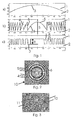
Bezüglich der Gestaltung entsprechender Gitter wird der Einfachheit halber auf die beiliegende Figur 1 verwiesen, wobei die obere Darstellung a) den Querschnitt einer normalen, refraktiven Linse zeigt, während die mittlere Darstellung b) schematisch den Querschnitt durch eine diffraktive Linse mit jeweils einer senkrecht zur Gitter-Hauptebene verlaufenden Flanke und einer demgegenüber schrägen Flanke je Gitterfurche zeigt. In der Darstellung c) der Figur 1 ist eine sogenannte "Binärstruktur" dargestellt, bei der Gitterfurchen und Gitterstege jeweils rechteckigen Querschnitt aufweisen und, wie Figur 1 c) erkennen läßt, die Breite der Gitterstege und die Breite der Gitterfurchen sich von der Linsenmitte zum Rand der Linse zu vermindert. Alle drei in Figur 1 gezeigten Linsenformen erzeugen, wenn man auf eine bestimmte Wellenlänge abstellt, grundsätzlich den gleichen optischen Effekt. Die Besonderheit der erfindungsgemäß vorgeschlagenen diffraktiven Linsenstrukturen ist aber, daß diese - anders als refraktive Linsen - abhängig von der jeweils vorhandenen Licht-Wellenlänge einen verschiedenen visuellen Eindruck erzeugen. Trotzdem ist die Höhe der die diffraktiven Linsen gemäß Figur 1b) und Figur 1c) bildenden Struktur um ein Vielfaches geringer als die Dicke der entsprechenden refraktiven Linse gemäß Figur 1a. Erst hierdurch wird es möglich, die Linsenstruktur in eine Schichtanordnung einzugliedern ohne mit extremen, in der Praxis ausgeschlossenen Schichtdicken arbeiten zu müssen.With regard to the design of corresponding gratings, reference is made to the accompanying Figure 1 for the sake of simplicity, the upper representation a) showing the cross section of a normal, refractive lens, while the middle representation b) schematically showing the cross section through a diffractive lens with one perpendicular to the grating Main plane extending edge and a contrast oblique edge per grid groove shows. In the representation c) of Figure 1, a so-called "binary structure" is shown, in the lattice grooves and lattice webs each have rectangular cross-section and, as Figure 1 c) reveals, the width of the lattice webs and the width of the lattice grooves from the lens center to the edge the lens is reduced. All three lens shapes shown in Figure 1, when turned off to a certain wavelength, basically produce the same optical effect. The peculiarity of the diffractive lens structures proposed according to the invention, however, is that, unlike refractive lenses, they produce a different visual impression depending on the particular wavelength of light present. Nevertheless, the height of the structure forming the diffractive lenses according to FIG. 1b) and FIG. 1c) is many times smaller than the thickness of the corresponding refractive lens according to FIG. 1a. Only then is it possible to incorporate the lens structure in a layer arrangement without having to work with extreme, excluded in practice layer thicknesses.
Wenn Linsenstrukturen gemäß der Erfindung verwendet werden, erzielt man zum einen den Vorteil, daß sich eine höhere Effizienz gegenüber holographisch hergestellten Linsenstrukturen erzeugen läßt, was zur Folge hat, daß das unter Zuhilfenahme der Linse gebildete Bild bzw. der entsprechende Dekorations- oder Sicherheitseffekt brillanter erscheinen. Weiterhin lassen sich die erfindungsgemäßen Linsenstrukturen mit sehr hoher Genauigkeit - im Vergleich zu holographisch hergestellten Strukturen - erzeugen, wodurch das visuelle Erscheinungsbild deutlich verbessert wird. Schließlich ist es durch geeignete Wahl der Gitterkonstanten (Gitterfrequenz, Gittertiefe etc.) bei den erfindungsgemäßen Linsenstrukturen möglich, spezielle Farbeffekte zu erzielen bzw. die Farbeffekte über das Gesamtprofil der Linsenstruktur in vorgegebener Weise zu steuern. Weiterhin sei in diesem Zusammenhang auf die Möglichkeit hingewiesen, die Linsenstrukturen mit anderen, optische Effekte bewirkenden Elementen, z.B. andersartigen Beugungsstrukturen zur Erzielung von Bewegungseffekten, Flips oder dergleichen oder mit Dünnschichtanordnungen zur Erzielung besonderer Farbeffekte zu kombinieren, wie dies allgemein z.B. von optisch variablen Sicherheitselementen bekannt ist. Linsenstrukturen gemäß der Erfindung haben somit gegenüber holographisch erzeugten Linsenstrukturen neben der Gemeinsamkeit der geringen "Dicke" eine große Vielzahl von Vorteilen.When lens structures according to the invention are used, on the one hand, there is the advantage of being able to produce a higher efficiency compared to holographically produced lens structures, with the result that the image formed with the aid of the lens or the corresponding decorative or security effect appears more brilliant , Furthermore, the lens structures according to the invention can be produced with very high accuracy-in comparison to holographically produced structures-whereby the visual appearance is markedly improved. Finally, it is possible by suitable choice of the lattice constants (grating frequency, grating depth, etc.) in the lens structures according to the invention to achieve special color effects or to control the color effects over the overall profile of the lens structure in a predetermined manner. Furthermore, in this context, attention should be drawn to the possibility of the lens structures with other, optical effects causing elements, such as other diffraction structures to achieve motion effects, flips or the like or with Thin film arrangements to achieve special color effects to combine, as is generally known, for example, of optically variable security elements. Lens structures according to the invention thus have, in addition to the commonality of the small "thickness", a wide variety of advantages over holographically produced lens structures.
Schichtanordnungen mit einer Linsenstruktur gemäß der Erfindung können sowohl bei Betrachtung in Transmission als auch bei Reflexion entsprechende spezielle optische Effekte erzeugen. Um eine Betrachtung in Transmission zu ermöglichen, ist nach der Erfindung vorgesehen, daß die der Grenzfläche benachbarten Schichten transparent sind und einen deutlich, vorzugsweise um wenigstens 0,2 verschiedenen Brechungsindex aufweisen. Durch den Unterschied im Brechungsindex erreicht man, daß die Linsenwirkung der Grenzfläche trotz des Umstandes, daß das Licht durch die Schichtanordnung hindurchtritt, doch einen deutlich sichtbaren Effekt bewirkt. Speziell beim Arbeiten in Transmission kann die Gitterstruktur einseitig nicht abgedeckt sein sondern an Luft anschließen.Layer arrangements with a lens structure according to the invention can produce corresponding special optical effects both when viewed in transmission and in reflection. In order to enable a viewing in transmission, it is provided according to the invention that the layers adjacent to the interface are transparent and have a distinct, preferably at least 0.2 different refractive index. Due to the difference in the refractive index, it is achieved that the lens effect of the interface, despite the fact that the light passes through the layer arrangement, but causes a clearly visible effect. Especially when working in transmission, the lattice structure can not be covered on one side but connected to air.
Es liegt weiter im Rahmen der Erfindung, daß die Grenzfläche zumindest bereichsweise mit einer reflexionserhöhenden Schicht versehen ist, wobei die reflexionserhöhende Schicht zweckmäßig eine, beispielsweise aufgedampfte, Metallschicht ist. Es wäre jedoch durchaus denkbar, als reflexionserhöhende Schicht eine transparente Schicht mit einem entsprechend hohen Brechungsindex vorzusehen, in welchem Falle man in gewissem Umfang eine Durchlässigkeit der Schichtanordnung erreichen könnte. Auch Dünnschichtanordnungen der bekannten Kombinationen oder Halbleiterschichten könnten verwendet werden.It is further within the scope of the invention that the interface is at least partially provided with a reflection-enhancing layer, wherein the reflection-enhancing layer is expediently a, for example vapor-deposited, metal layer. However, it would certainly be conceivable to provide a transparent layer with a correspondingly high refractive index as a reflection-enhancing layer, in which case it would be possible to achieve a certain degree of permeability of the layer arrangement. Thin-film arrangements of the known combinations or semiconductor layers could also be used.
Bei der bekannten Kreditkarte umfaßt das von einer Schichtanordnung der gattungsgemäßen Art gebildete holographisch erzeugte Sicherheitselement lediglich eine kreisförmige Linsenstruktur. Verwendet man nun dagegen eine diffraktive Linsenstruktur gemäß der Erfindung, ist es möglich, über die Fläche der Schichtanordnung mehrere Linsenstrukturen verteilt anzuordnen, wodurch sich einerseits wesentlich interessantere Effekte (für den Fall der Verwendung zu Dekorationszwecken) erzielen lassen oder, sofern die Linsenstruktur Teil eines Sicherheitselementes ist, auch die Sicherheitswirkung erhöhen läßt. Zweckmäßig sind in einem derartigen Fall die mehreren Linsenstrukturen in einem Raster angeordnet, wodurch die Verifikation erleichtert werden kann. Aber auch eine zumindest bereichsweise Überlappung der Linsenstrukturen wäre denkbar, wobei eine Verschachtelung sogar in der Art möglich wäre, daß abhängig vom Betrachtungswinkel unterschiedliche Linsenstrukturen in Erscheinung treten.In the known credit card formed by a layer arrangement of the generic type holographically generated security element comprises only a circular lens structure. By contrast, if a diffractive lens structure according to the invention is used, it is possible to arrange a plurality of lens structures distributed over the surface of the layer arrangement, which on the one hand yields much more interesting effects (in the case of use for decorative purposes) or, if the lens structure is part of a security element is, also allows to increase the safety effect. expedient In such a case, the plurality of lens structures are arranged in a grid, whereby the verification can be facilitated. But also an at least partially overlapping of the lens structures would be conceivable, wherein an interleaving would even be possible in the way that different lens structures appear depending on the viewing angle.
Besonders einfach wird die Herstellung entsprechender Linsenstrukturen oder Linsenstruktur-Anordnungen, wenn, wie nach der Erfindung vorgesehen, die Linsenstrukturen im wesentlichen kreisförmig mit konzentrisch verlaufenden Gitterlinien ausgebildet sind.The production of corresponding lens structures or lens structure arrangements becomes particularly simple when, as provided according to the invention, the lens structures are formed essentially circular with concentrically extending grid lines.
Für die Praxis als zweckmäßig hat es sich erwiesen, wenn die Linsenstrukturen einen Durchmesser zwischen 0,15 und 300 mm, vorzugsweise zwischen 3 und 50 mm aufweisen.It has proven to be expedient in practice if the lens structures have a diameter between 0.15 and 300 mm, preferably between 3 and 50 mm.
Wenn, wie nach der Erfindung weiter vorgesehen, die Gittertiefe der Linsenstrukturen kleiner als 5 µm, vorzugsweise kleiner als 3 µm ist, lassen sich derartige Gitterstrukturen ohne Probleme in die üblicherweise bei Transfer- oder Laminierfolien vorgesehenen Lackschichten, die in etwa diese Dicke haben, einbringen.If, as further provided according to the invention, the lattice depth of the lens structures is smaller than 5 .mu.m, preferably smaller than 3 .mu.m, such lattice structures can be introduced without problems into the lacquer layers conventionally provided in transfer or laminating foils, which have approximately this thickness ,
Es wird nach der Erfindung vorgeschlagen, daß die Binärstruktur über die gesamte Fläche der Linsenstruktur in etwa die gleiche Tiefe besitzt. Hierdurch wird die Herstellung besonders einfach. Über die Wahl der Tiefe der Binärstruktur läßt sich dabei Einfluß auf die Farbe nehmen, die bei Betrachtung der Linsenstruktur für den Beobachter entsteht.It is proposed according to the invention that the binary structure has approximately the same depth over the entire surface of the lens structure. As a result, the production is particularly simple. By choosing the depth of the binary structure, it is possible to influence the color which arises when the lens structure is considered by the observer.
Schließlich kann es vorteilhaft sein, wenn die transparente(n), dem Beobachter zugeheftete(n) Schicht(en) pigmentfrei eingefärbt ist (sind).Finally, it may be advantageous if the transparent layer (s) adhered to the observer is (are) dyed pigment-free.
Weitere Merkmale, Einzelheiten und Vorteile der Erfindung ergeben sich aus der folgenden Beschreibung bevorzugter Ausführungsbeispiele an Hand der Zeichnung.Further features, details and advantages of the invention will become apparent from the following description of preferred embodiments with reference to the drawing.
Es zeigen:
Figur 1- schematisch und im Querschnitt
- a) eine refraktive Linse
- b) eine diffraktive Linse mit im Querschnitt etwa dreieckförmigen Gitterfurchen,
- c) eine Linse mit einer diffraktiven Binärstruktur;
Figur 2- in schematischer Draufsicht ein in einer Schichtanordnung gemäß der Erfindung vorgesehenes Sicherheits- oder Dekorationselement mit einer erfindungsgemäßen Linsenstruktur, und
Figur 3- eine Darstellung
ähnlich Figur 2, allerdings in kleinerem Maßstab und bei einer Schichtanordnung mit mehreren, in Form eines Rasters angeordneten Linsenstrukturen.
- FIG. 1
- schematically and in cross section
- a) a refractive lens
- b) a diffractive lens with cross-sectionally approximately triangular grid grooves,
- c) a lens with a diffractive binary structure;
- FIG. 2
- in a schematic plan view provided in a layer arrangement according to the invention security or decorative element with a lens structure according to the invention, and
- FIG. 3
- a representation similar to Figure 2, but on a smaller scale and in a layer arrangement with a plurality of arranged in the form of a grid lens structures.
In den schematischen Querschnittsdarstellungen der Figur 1 ist gezeigt, daß die Schichtanordnung gemäß der Erfindung jeweils zwei Materialschichten 1, 2 aufweist, die zwischen sich eine Grenzfläche 3 bilden, die beispielsweise mit einer Metallisierung, z.B. einer im Vakuum aufgedampften Metallschicht, versehen sein kann. Für bestimmte Anwendungsfälle kann dabei eine der Materialschichten 1, 2 durch Luft gebildet sein. Der Durchmesser der Linsen in Figur 1 ist auf der x-Achse in beliebig angenommenen Einheiten gezeigt, da es auf die genaue Größe bzw. den genauen Durchmesser der Linsenstrukturen nicht ankommt. Der Durchmesser der Linsenstrukturen liegt jedoch im allgemeinen zwischen 0,15 und 300 mm, vorzugsweise zwischen 3 und 50 mm, wobei die Brennweite der Linsen üblicherweise zwischen dem Wert des Linsendurchmessers und dem fünffachen dieses Wertes liegt.In the schematic cross-sectional representations of Figure 1 it is shown that the layer arrangement according to the invention comprises two
Auf der y-Achse in Figur 1 ist jeweils die Dicke bzw. die Höhe der entsprechenden Schicht 1, 2 bzw. Struktur aufgetragen, wobei es sich bei den angegebenen Werten um die Phasendifferenz in Radiant handelt. Bei Verwendung einer bestimmten Licht-Wellenlänge (z.B. 550 nm für die maximale Empfindlichkeit des menschlichen Auges) läßt sich aus dieser Phasendifferenz in bekannter Weise (auch unter Berücksichtigung der jeweiligen Brechungsindices) die geometrische Tiefe berechnen. Aus einem Vergleich der Figur 1a) mit den Figuren 1b) und 1c) ist ohne weiteres ersichtlich, daß die Dicke der Schichtanordnung gemäß Figur 1a) wenigstens zehn Mal so groß sein muß wie die Dicke der Schichtanordnung gemäß Figur 1b) und sogar etwa zwanzig Mal so groß wie die Dicke der Schichtanordnung der Figur 1c). Daß die Schichtanordnungen der Figuren 1b) und 1c) wesentlich dünner sein können als die der Figur 1a) beruht auf der geringeren Gesamthöhe 9 der von der Grenzschicht 3 bestimmten Linsenstruktur, die sich nur über eine Höhe erstreckt, die umgerechnet (für ein System n=1,5/n=1 in Transmission) bei Figur 1b) etwa der doppelten Wellenlänge, in Figur 1c) sogar nur etwa der einfachen Wellenlänge entspricht.The thickness or height of the
Bei den Schichten 1 und 2 der Schichtanordnung handelt es sich im allgemeinen um Lackschichten entsprechender Zusammensetzung, wobei wenigstens die dem Beobachter zugekehrte Lackschicht (im vorliegenden Falle im allgemeinen die Schicht 1) weitgehend transparent sein muß, allerdings dabei gefärbt sein kann. Für bestimmte Anwendungsfälle kann eine der Schichten eine Kleberschicht sein oder die dem Betrachter zugekehrte Schicht sogar entfallen.
Wenn die Grenzschicht 3 mit einer Metallisierung oder einer sonstigen, stark reflektierenden Beschichtung versehen ist, kann die Schicht 2 ebenfalls transparent, aber auch durchscheinend oder undurchsichtig sein. Soll dagegen die Schichtanordnung gemäß der Erfindung in Transmission eingesetzt werden, beispielsweise zur Abdeckung eines auf einem Substrat vorhandenen sichtbaren Merkmals, muß auch die Schicht 2 transparent sein. In diesem Falle wird die Grenzfläche 3 nicht mit einer- im allgemeinen undurchsichtigen - Metallisierung versehen werden. Statt dessen wird man den Brechungsindex der beiden transparenten Schichten 1 und 2 derart unterschiedlich wählen (wobei die Differenz des Brechungsindex vorzugsweise wenigstens 0,2 betragen sollte), daß trotz Verwendung zweier transparenter Schichten der durch die Grenzfläche 3 erzeugte Effekt optisch hinreichend deutlich sichtbar wird.If the
Die Linsenstruktur gemäß Figur 1b wird üblicherweise in einem sogenannten "Direktschreib-Verfahren" erzeugt, d.h. in einem Verfahren, bei dem entweder mittels eines Lasers das Material gemäß dem gewünschten Profil abgetragen wird oder mittels eines Lasers oder einer Elektronenstrahl-Lithographieeinrichtung ein Photoresist gemäß dem gewünschten Profil belichtet wird und anschließend durch Entwicklung des Photoresists das gewünschte Profil bzw. dessen Negativprofil erhalten wird. Diese Vorgehensweise bietet den Vorteil, daß sich sehr unterschiedliche Gitterstrukturen und insbesondere Gitterquerschnitte, z.B. auch für bestimmte Anwendungsfälle sogenannte Blaze-Gitter, erzeugen lassen, wobei insbesondere erreicht werden kann, daß der Winkel α zwischen den in Figur 1b) schräg verlaufenden Flanken 4 der Gitterfurchen und einer Senkrechten S auf die Hauptebene der Linsenstruktur sich- wie aus Figur 1b) deutlich ersichtlich - kontinuierlich vom Zentrum der Linse aus nach außen verändert, und zwar in dem Sinn, daß die zu der Senkrechten S etwa parallelen Flanken 5 der Gitterfurchen gleichsam nur Unstetigkeitsstellen in einem ansonsten im wesentlichen stetigen Linsenprofil, welches durch die jeweils anderen, schrägen Flanken 4 der Gitterfurchen sowie den zentrischen, paraboloidförmigen Abschnitt 6 der Grenzfläche 3 gebildet ist, darstellen.The lens structure according to FIG. 1b is usually produced in a so-called "direct writing process", ie in a process in which the material is either removed by means of a laser in accordance with the desired profile or a photoresist is exposed according to the desired profile by means of a laser or an electron beam lithography device, and then the desired profile or its negative profile is obtained by developing the photoresist. This procedure offers the advantage that it is possible to produce very different lattice structures and, in particular, lattice cross sections, for example also so-called blaze lattices for certain applications, it being possible in particular to achieve that the angle α between the edges 4 of the lattice grooves running obliquely in FIG. 1b) and a perpendicular S on the main plane of the lens structure as clearly seen in Figure 1b) - continuously outwardly from the center of the lens, in the sense that the approximately parallel to the vertical S flanks 5 of the lattice grooves as it were only points of discontinuity in an otherwise substantially continuous lens profile, which is formed by the respective other, oblique edges 4 of the lattice grooves and the central,
Derartige Linsenstrukturen sowie die Art ihrer Berechnung sind grundsätzlich in der Literatur beschrieben, weshalb hierauf nicht näher eingegangen werden soll.Such lens structures as well as the nature of their calculation are basically described in the literature, which is why this will not be discussed in detail.
Dabei ist auch die Möglichkeit zu erwähnen, anstelle der gemäß Figur 1 b über die Höhe 9 kontinuierlichen schrägen Flanken 4 eine stufenförmige Anordnung zu verwenden, bei welcher die die Stufen bildenden Flächen die Flanken 4 in ihrer optischen Wirkung annähern. Derartige Gitterstrukturen können sowohl in sog. Direkt-Schreibverfahren als auch über geeignete Masken-Techniken erzeugt werden, wobei die Zahl der Stufen abhängig von dem angestrebten Ergebnis variiert werden kann. Für eine Vielzahl von Anwendungsfällen genügt dabei bereits eine Aufteilung in vier oder acht Stufen. Bei hohen Qualitätsanforderungen ist es aber beispielsweise auch möglich, vierundsechzig Stufen oder eine Stufenzahl gemäß einer höheren Potenz von 2 vorzusehen.In this case, it is also possible to mention, instead of the continuous oblique flanks 4 according to FIG. 1 b, to use a stepped arrangement in which the surfaces forming the steps approximate the flanks 4 in their optical action. Such grating structures can be produced both in so-called direct write methods and via suitable mask techniques, wherein the number of stages can be varied depending on the desired result. Already sufficient for a variety of applications, a division into four or eight stages. For high quality requirements, however, it is also possible, for example, to provide sixty-four steps or a number of steps according to a higher power of 2.
Die Binärstruktur gemäß Figur 1c) wird unter Verwendung entsprechender Masken hergestellt. Das wesentliche Charakteristikum der Binärstruktur gemäß Figur 1c) ist darin zu sehen, daß sowohl die Gitterfurchen 7 als auch die Gitterstege 8 jeweils im Querschnitt im wesentlichen rechteckig sind. Eine weitere Besonderheit der Struktur gemäß Figur 1c) ist darin zu sehen, daß die Gittertiefe 9 über die gesamte Linsenstruktur einheitlich ist, was insbesondere bei der Herstellung den Vorteil bietet, daß weder unterschiedliche Einwirkungszeiten des das Material entfernenden Mittels vorgesehen noch mit unterschiedlichen Intensitäten des durch die entsprechende Maske auf das Substrat einwirkenden Mittels gearbeitet werden muß.The binary structure according to FIG. 1c) is produced using corresponding masks. The essential characteristic of the binary structure according to FIG. 1c) can be seen in that both the grating grooves 7 and the
In Figur 2 ist schematisch (tatsächlich sind die Abstände der Gitterlinien wesentlich geringer) ein linsenartiges Element gezeigt, das mit einer Linsenstruktur gemäß Figur 1b) hergestellt ist, wobei die Draufsicht der Figur 2 deutlich den sich ständig vermindernden Abstand zwischen den einzelnen Gitterstegen bzw. die sich ständig vom Zentrum der kreisförmigen Linse zu deren Rand zu erhöhende Gitterfrequenz erkennen läßt. Zusätzlich ist auch die Neigung der in der Draufsicht der Figur 2 sichtbaren Gitterflanken 4 von dem Zentrum der Linse nach außen ständig und im wesentlichen kontinuierlich verändert. Auch die zur Linsen-Hauptebene senkrechten Gitterflanken 5 sind in Form dunkler Linien in Figur 2 deutlich sichtbar.In Figure 2 is schematically (actually the distances of the grid lines are much lower) shown a lens-like element, which is made with a lens structure according to Figure 1b), the plan view of Figure 2 clearly the ever decreasing distance between the grid bars or the can be constantly seen from the center of the circular lens to its edge increasing grid frequency. In addition, the inclination of the visible in the plan view of Figure 2 lattice edges 4 from the center of the lens to the outside is constantly changing and substantially continuously. Also, the grid edges 5 perpendicular to the lens main plane are clearly visible in the form of dark lines in FIG.
Die Figur 3 zeigt eine weitere Möglichkeit, wie in einer erfindungsgemäßen Schichtanordnung diffraktive Linsenstrukturen vorgesehen sein können.FIG. 3 shows a further possibility of how diffractive lens structures can be provided in a layer arrangement according to the invention.
In dem Ausführungsbeispiel der Figur 3, das beispielsweise bei einer dekorativen Transfer- oder Laminierfolie verwirklicht sein könnte, sind über die Oberfläche der Folie verteilt in mehreren, in einem Raster angeordneten Flächenbereichen kreisförmige Linsenstrukturen angeordnet, die prinzipiell den Linsenstrukturen der Figur 2 entsprechen können. Die Anordnung ist dabei so gewählt, daß nicht die äußeren Gitterfurchen entsprechend Figur 2 teilweise abgeschnitten sind. Die Linsenstrukturen 10 der Figur 3 sind vielmehr jeweils insgesamt kreisförmig erhalten. Die hierdurch bei einer Aneinanderreihung entsprechender Linsenstruktur-Kreise entstehenden Zwischenräume in Form von sphärischen Quadraten sind bei der Schichtanordnung der Figur 3 durch entsprechend gestaltete Beugungsstrukturen 11 ausgefüllt, die durchaus ebenfalls einen Linseneffekt erzeugen können, wobei beispielsweise die Linsenstrukturen 10 den Effekt von Sammellinsen zeigen, während die Strukturen 11 als Zerstreuungslinsen wirken, wodurch sich der optische Effekt beider Linsenarten quasi verstärken läßt.In the exemplary embodiment of FIG. 3, which could be realized, for example, in the case of a decorative transfer or laminating film, circular lens structures are arranged distributed over the surface of the film in a plurality of surface areas arranged in a grid, which in principle can correspond to the lens structures of FIG. The arrangement is chosen so that not the outer grid grooves corresponding to Figure 2 are partially cut off. Rather, the
Es ist selbstverständlich möglich, durch entsprechende Kombination der unterschiedlichsten Linsenstrukturen Schichtanordnungen mit komplexen, optisch wirksamen Effekten zu erzeugen, wobei es natürlich auch denkbar ist, diffraktive Strukturen zusätzlich und bereichsweise vorzusehen, die völlig andersartige Effekte, beispielsweise Bewegungseffekte, Flips etc., generieren. Auch ist es denkbar, die Linsenstrukturen und/oder sonstige diffraktive Strukturen mit einer Dünnschichtfolge mit speziellen Farben, z.B. OVI, oder mit Halbleiterschichten zu kombinieren, um so spezielle Farbwechseleffekte zu erzielen.It is of course possible to produce layer arrangements with complex, optically effective effects by appropriate combination of the most diverse lens structures, whereby it is naturally also conceivable to additionally and partially provide diffractive structures which generate completely different types of effects, for example motion effects, flips, etc. It is also conceivable to use the lens structures and / or other diffractive structures with a thin-layer sequence with special colors, e.g. OVI, or to combine with semiconductor layers, so as to achieve special color change effects.
Besonders interessante Gestaltungen der Schichtanordnungen ergeben sich dann, wenn die Grenzschicht 3 nur teilweise mit einer Metallisierung versehen ist, wobei z.B. eine Demetallisierung im Register mit den Linsenstrukturen vorgesehen sein kann.Particularly interesting designs of the layer arrangements arise when the
Weiterhin müssen selbstverständlich die Linsenstrukturen nicht, wie dies in der Zeichnung im allgemeinen dargestellt ist, jeweils kreisförmig sein. Ein Vorteil der Verwendung diffraktiver Linsenstrukturen ist gerade der, daß diese auch anderen Formen (sogenannten Freiformflächen) überlagert werden können, um so beispielsweise drei-dimensional erscheinende Gebilde zu generieren. Weiterhin wäre es z.B. auch denkbar, die Linsenstruktur der Figur 2 zu unterteilen und in anderer Weise die Teile wieder zusammenzusetzen, wodurch sich ebenfalls sehr interessante optische Effekte erzielen lassen.Furthermore, of course, the lens structures do not have to be circular, as shown generally in the drawing. An advantage of using diffractive lens structures is precisely that they can also be superimposed on other shapes (so-called free-form surfaces) in order, for example, to generate three-dimensional structures. Furthermore, it would be e.g. also conceivable to divide the lens structure of Figure 2 and otherwise reassemble the parts, which can also be achieved very interesting optical effects.
Claims (11)
- Layer arrangement, in particular for transfer or laminating films, having at least two consecutive material layers, of which at least the layer or layers facing the observer during use is or are transparent and between which an interface is formed which is provided, at least in a surface area, with a structure which is active in terms of optical diffraction and produces a lens-type magnification or reduction effect, characterized in that the structure (4, 5, 6; 7, 8), which is active in terms of optical diffraction and produces the lens-type effect, is a grating structure which varies continuously over the surface area with respect to its grating frequency and possibly further grating constants and is either a binary structure or designed in a manner such (Figure 1b) that the in each case first flanks (5) of the grating grooves extend parallel to one another and approximately parallel to a perpendicular (S) to the main plane of the interface, whereas the angle (α) of the in each case second flanks (4) of the grating faces with respect to a perpendicular (S) to the main plane of the interface (3) varies substantially continuously over the surface area, the grating depth (9) of the grating structures being not more than 10 µm.
- Layer arrangement according to Claim 1, characterized in that the layers (1, 2) adjoining the interface (3) are transparent and have a different refractive index, preferably one that differs by at least 0.2.
- Layer arrangement according to Claim 1, characterized in that the interface (3) is provided with a reflection-increasing layer at least in regions.
- Layer arrangement according to Claim 3, characterized in that the reflection-increasing layer is a metal layer.
- Layer arrangement according to one of the preceding claims, characterized in that a plurality of lens structures (10, 11) are arranged such that they are distributed over the area of the layer arrangement.
- Layer arrangement according to Claim 5, characterized in that the plurality of lens structures (10, 11) are arranged in a grid.
- Layer arrangement according to one of the preceding claims, characterized in that the lens structures (10) are designed such that they are substantially circular with concentrically extending grating lines.
- Layer arrangement according to one of the preceding claims, characterized in that the lens structures (10) have a diameter of between 0.15 and 300 mm, preferably between 3 and 50 mm.
- Layer arrangement according to one of the preceding claims, characterized in that the grating depth (9) of the lens structures is less than 5 µm, preferably less than 2 µm.
- Layer arrangement according to one of the preceding claims, characterized in that the depth (9) of the binary structure is approximately the same over the entire area of the lens structure (10).
- Layer arrangement according to one of the preceding claims, characterized in that the transparent layers facing the observer are dyed without pigment.
Applications Claiming Priority (3)
| Application Number | Priority Date | Filing Date | Title |
|---|---|---|---|
| DE10254499A DE10254499B4 (en) | 2002-11-22 | 2002-11-22 | Layer arrangement with a lens-like effect generating diffractive optical effective structure |
| DE10254499 | 2002-11-22 | ||
| PCT/EP2003/012451 WO2004049250A1 (en) | 2002-11-22 | 2003-11-07 | Layer arrangement provided with a structure producing a diffractive optical effect and a lens-type effect |
Publications (2)
| Publication Number | Publication Date |
|---|---|
| EP1570422A1 EP1570422A1 (en) | 2005-09-07 |
| EP1570422B1 true EP1570422B1 (en) | 2007-05-16 |
Family
ID=32318619
Family Applications (1)
| Application Number | Title | Priority Date | Filing Date |
|---|---|---|---|
| EP03775318A Expired - Lifetime EP1570422B1 (en) | 2002-11-22 | 2003-11-07 | Layer arrangement provided with a structure producing a diffractive optical effect and a lens-type effect |
Country Status (14)
| Country | Link |
|---|---|
| US (1) | US7227690B2 (en) |
| EP (1) | EP1570422B1 (en) |
| JP (1) | JP4510636B2 (en) |
| KR (1) | KR100974682B1 (en) |
| CN (1) | CN100419789C (en) |
| AT (1) | ATE362627T1 (en) |
| AU (1) | AU2003283371B2 (en) |
| DE (2) | DE10254499B4 (en) |
| ES (1) | ES2287538T3 (en) |
| MY (1) | MY138939A (en) |
| PL (1) | PL375554A1 (en) |
| RU (1) | RU2317574C2 (en) |
| TW (1) | TWI306514B (en) |
| WO (1) | WO2004049250A1 (en) |
Cited By (1)
| Publication number | Priority date | Publication date | Assignee | Title |
|---|---|---|---|---|
| WO2012000669A1 (en) | 2010-07-01 | 2012-01-05 | Giesecke & Devrient Gmbh | Security element, and value document comprising such a security element |
Families Citing this family (22)
| Publication number | Priority date | Publication date | Assignee | Title |
|---|---|---|---|---|
| DE10254500B4 (en) * | 2002-11-22 | 2006-03-16 | Ovd Kinegram Ag | Optically variable element and its use |
| US7251398B2 (en) * | 2004-08-26 | 2007-07-31 | Interuniversitair Microelektronica Centrum (Imec) | Method for providing an optical interface and devices according to such methods |
| DE102004044459B4 (en) * | 2004-09-15 | 2009-07-09 | Ovd Kinegram Ag | Security document with transparent windows |
| DE102005017170B4 (en) | 2005-04-13 | 2010-07-01 | Ovd Kinegram Ag | Transfer film, process for their preparation and multilayer body and its use |
| DE102005017169B4 (en) | 2005-04-13 | 2023-06-22 | Ovd Kinegram Ag | transfer film |
| DE102005027380B4 (en) | 2005-06-14 | 2009-04-30 | Ovd Kinegram Ag | The security document |
| DE102005061749A1 (en) | 2005-12-21 | 2007-07-05 | Giesecke & Devrient Gmbh | Optically variable security element for making valuable objects safe has an achromatic reflecting micro-structure taking the form of a mosaic made from achromatic reflecting mosaic elements |
| US7973990B2 (en) * | 2006-04-27 | 2011-07-05 | Ricoh Company, Ltd. | Optical scanning device, optical writing device, and image forming apparatus |
| US8133638B2 (en) * | 2006-05-30 | 2012-03-13 | Brady Worldwide, Inc. | All-polymer grating microstructure |
| TW200913238A (en) * | 2007-06-04 | 2009-03-16 | Sony Corp | Optical member, solid state imaging apparatus, and manufacturing method |
| ES2320520B1 (en) * | 2007-11-21 | 2010-03-04 | Joaquin Devesa Company | PROCEDURE FOR OBTAINING A LENTICULAR SHEET AND SHEET SO OBTAINED. |
| FR2959830B1 (en) | 2010-05-07 | 2013-05-17 | Hologram Ind | OPTICAL AUTHENTICATION COMPONENT AND METHOD FOR MANUFACTURING THE SAME |
| DE102010019766A1 (en) | 2010-05-07 | 2011-11-10 | Giesecke & Devrient Gmbh | Method for producing a microstructure on a support |
| RU2430836C1 (en) | 2010-07-29 | 2011-10-10 | Федеральное Государственное Унитарное Предприятие "Гознак" (Фгуп "Гознак") | Multilayer protective element with alternate optical effect and counterfeit-proof document |
| CN102981194B (en) * | 2012-11-23 | 2015-04-01 | 中国科学院物理研究所 | One-piece type optical element and design method of one-piece type diffraction optical element |
| FR3000112B1 (en) | 2012-12-20 | 2015-03-06 | Arjowiggins Security | SAFETY STRUCTURE. |
| DE102015100280A1 (en) * | 2015-01-09 | 2016-07-14 | Ovd Kinegram Ag | Method for the production of security elements and security elements |
| GB2545387A (en) | 2015-07-24 | 2017-06-21 | De La Rue Int Ltd | Security device and method of manufacturing thereof |
| GB201513096D0 (en) | 2015-07-24 | 2015-09-09 | Rue De Int Ltd | Diffractive security device and method of manufacturing thereof |
| JP2018114696A (en) | 2017-01-19 | 2018-07-26 | 凸版印刷株式会社 | Display body |
| UA127132C2 (en) * | 2017-09-29 | 2023-05-10 | Сікпа Холдінг Са | Thin optical security element and method of designing it |
| DE102018103236A1 (en) | 2018-02-14 | 2019-08-14 | Leonhard Kurz Stiftung & Co. Kg | Security element and method for producing a security element |
Family Cites Families (19)
| Publication number | Priority date | Publication date | Assignee | Title |
|---|---|---|---|---|
| CA1267173A (en) * | 1985-09-23 | 1990-03-27 | Thomas I. Bradshaw | Sheet containing contour-dependent directional image and method for forming the same |
| DE3687560D1 (en) * | 1985-10-15 | 1993-03-04 | Gao Ges Automation Org | DATA CARRIER WITH AN OPTICAL AUTHENTICITY CHARACTER, AND METHOD FOR PRODUCING AND CHECKING THE DATA CARRIER. |
| GB9309673D0 (en) * | 1993-05-11 | 1993-06-23 | De La Rue Holographics Ltd | Security device |
| CN1063552C (en) * | 1995-02-28 | 2001-03-21 | 中国科学技术大学 | Method for making quantum line ultra-fine figure |
| JP3618465B2 (en) * | 1996-05-31 | 2005-02-09 | オリンパス株式会社 | Diffractive optical element and optical apparatus using the same |
| JP3618464B2 (en) * | 1995-08-29 | 2005-02-09 | オリンパス株式会社 | Diffractive optical element and optical apparatus using the same |
| DE69636991T2 (en) | 1995-11-28 | 2007-12-06 | Ovd Kinegram Ag | Optical information carrier |
| JPH10116016A (en) * | 1996-10-09 | 1998-05-06 | Dainippon Printing Co Ltd | Optical diffraction pattern molding |
| AUPO289296A0 (en) * | 1996-10-10 | 1996-10-31 | Securency Pty Ltd | Self-verifying security documents |
| US5969864A (en) * | 1997-09-25 | 1999-10-19 | Raytheon Company | Variable surface relief kinoform optical element |
| JP3479449B2 (en) * | 1998-02-04 | 2003-12-15 | 沖電気工業株式会社 | Method of manufacturing reflection type diffractive optical element |
| US6324004B1 (en) * | 1999-01-21 | 2001-11-27 | Ovd Kingegram Ag | Planar patterns with superimposed diffraction gratings |
| DE59911557D1 (en) * | 1999-08-12 | 2005-03-10 | Ovd Kinegram Ag Zug | disk |
| US6502757B1 (en) * | 1999-09-17 | 2003-01-07 | Dai Nippon Printing Co., Ltd. | Information recorded medium, device for reading the information, information recorded medium transfer foil, and method for producing information recorded medium |
| DE19949945A1 (en) * | 1999-10-16 | 2001-08-30 | Bundesdruckerei Gmbh | Data carriers with authenticity features and manufacturing processes therefor |
| JP2001332087A (en) * | 2000-05-19 | 2001-11-30 | Nec Corp | Sense amplifier circuit |
| JP3242638B2 (en) * | 2000-07-07 | 2001-12-25 | キヤノン株式会社 | Display element and display device |
| DE10054503B4 (en) * | 2000-11-03 | 2005-02-03 | Ovd Kinegram Ag | Light diffractive binary lattice structure and security element with such a lattice structure |
| DE10123230A1 (en) * | 2001-05-12 | 2002-11-28 | Zeiss Carl | Diffractive optical element and optical arrangement with a diffractive optical element |
-
2002
- 2002-11-22 DE DE10254499A patent/DE10254499B4/en not_active Expired - Fee Related
-
2003
- 2003-11-07 ES ES03775318T patent/ES2287538T3/en not_active Expired - Lifetime
- 2003-11-07 AT AT03775318T patent/ATE362627T1/en active
- 2003-11-07 JP JP2004554325A patent/JP4510636B2/en not_active Expired - Lifetime
- 2003-11-07 RU RU2005119642/28A patent/RU2317574C2/en active
- 2003-11-07 US US10/535,732 patent/US7227690B2/en not_active Expired - Lifetime
- 2003-11-07 CN CNB2003801039085A patent/CN100419789C/en not_active Expired - Fee Related
- 2003-11-07 EP EP03775318A patent/EP1570422B1/en not_active Expired - Lifetime
- 2003-11-07 WO PCT/EP2003/012451 patent/WO2004049250A1/en active IP Right Grant
- 2003-11-07 PL PL03375554A patent/PL375554A1/en not_active Application Discontinuation
- 2003-11-07 AU AU2003283371A patent/AU2003283371B2/en not_active Ceased
- 2003-11-07 KR KR1020057009173A patent/KR100974682B1/en active IP Right Grant
- 2003-11-07 DE DE50307303T patent/DE50307303D1/en not_active Expired - Lifetime
- 2003-11-12 TW TW092131640A patent/TWI306514B/en not_active IP Right Cessation
- 2003-11-18 MY MYPI20034412A patent/MY138939A/en unknown
Cited By (3)
| Publication number | Priority date | Publication date | Assignee | Title |
|---|---|---|---|---|
| WO2012000669A1 (en) | 2010-07-01 | 2012-01-05 | Giesecke & Devrient Gmbh | Security element, and value document comprising such a security element |
| DE102010025775A1 (en) | 2010-07-01 | 2012-01-05 | Giesecke & Devrient Gmbh | Security element and value document with such a security element |
| US10870305B2 (en) | 2010-07-01 | 2020-12-22 | Giesecke+Devrient Currency Technology Gmbh | Security element as well as value document having such a security element |
Also Published As
| Publication number | Publication date |
|---|---|
| RU2005119642A (en) | 2006-01-27 |
| JP4510636B2 (en) | 2010-07-28 |
| CN1714370A (en) | 2005-12-28 |
| ES2287538T3 (en) | 2007-12-16 |
| PL375554A1 (en) | 2005-11-28 |
| CN100419789C (en) | 2008-09-17 |
| JP2006507526A (en) | 2006-03-02 |
| DE10254499B4 (en) | 2005-12-22 |
| US7227690B2 (en) | 2007-06-05 |
| TWI306514B (en) | 2009-02-21 |
| MY138939A (en) | 2009-08-28 |
| AU2003283371B2 (en) | 2008-04-03 |
| ATE362627T1 (en) | 2007-06-15 |
| DE50307303D1 (en) | 2007-06-28 |
| US20060072225A1 (en) | 2006-04-06 |
| EP1570422A1 (en) | 2005-09-07 |
| AU2003283371A1 (en) | 2004-06-18 |
| RU2317574C2 (en) | 2008-02-20 |
| KR20050085086A (en) | 2005-08-29 |
| TW200428019A (en) | 2004-12-16 |
| WO2004049250A1 (en) | 2004-06-10 |
| KR100974682B1 (en) | 2010-08-06 |
| DE10254499A1 (en) | 2004-06-17 |
Similar Documents
| Publication | Publication Date | Title |
|---|---|---|
| EP1570422B1 (en) | Layer arrangement provided with a structure producing a diffractive optical effect and a lens-type effect | |
| EP1562758B1 (en) | Optically variable element and the use thereof | |
| EP2951031B1 (en) | Security element comprising groove or rib-shaped structural elements | |
| EP2451650B2 (en) | Multi-layer body | |
| EP2633344B1 (en) | Optically variable surface pattern | |
| EP3581395A2 (en) | Multilayer body | |
| WO2009024265A1 (en) | Grid image | |
| EP2934904B1 (en) | Security element with a lenticular image | |
| DE102010049600A1 (en) | Security element with optically variable surface pattern | |
| EP2853411B1 (en) | Security element with lenticular image | |
| EP3493996B1 (en) | Optically variable security element | |
| DE102011108242A1 (en) | Optically variable element, in particular security element | |
| EP2727742B1 (en) | Security element with lenticular image | |
| WO2004077468A2 (en) | Safety element | |
| EP3253584B1 (en) | Optically variable security element | |
| EP3242801A1 (en) | Method for producing security elements, and security elements | |
| EP3606765B1 (en) | Security element with relief structure and method for the production thereof | |
| WO2018172528A2 (en) | Security element, and method for producing a security element | |
| EP3648983B1 (en) | Optically variable security arrangement | |
| EP3921679B1 (en) | Grid structure image for representing a multi-colour diffraction image | |
| DE102022003386A1 (en) | Security element with nanostructures | |
| EP4353486A2 (en) | Security element with refractive structures and colour change |
Legal Events
| Date | Code | Title | Description |
|---|---|---|---|
| PUAI | Public reference made under article 153(3) epc to a published international application that has entered the european phase |
Free format text: ORIGINAL CODE: 0009012 |
|
| 17P | Request for examination filed |
Effective date: 20050507 |
|
| AK | Designated contracting states |
Kind code of ref document: A1 Designated state(s): AT BE BG CH CY CZ DE DK EE ES FI FR GB GR HU IE IT LI LU MC NL PT RO SE SI SK TR |
|
| AX | Request for extension of the european patent |
Extension state: AL LT LV MK |
|
| DAX | Request for extension of the european patent (deleted) | ||
| GRAP | Despatch of communication of intention to grant a patent |
Free format text: ORIGINAL CODE: EPIDOSNIGR1 |
|
| GRAS | Grant fee paid |
Free format text: ORIGINAL CODE: EPIDOSNIGR3 |
|
| GRAA | (expected) grant |
Free format text: ORIGINAL CODE: 0009210 |
|
| AK | Designated contracting states |
Kind code of ref document: B1 Designated state(s): AT BE BG CH CY CZ DE DK EE ES FI FR GB GR HU IE IT LI LU MC NL PT RO SE SI SK TR |
|
| PG25 | Lapsed in a contracting state [announced via postgrant information from national office to epo] |
Ref country code: FI Free format text: LAPSE BECAUSE OF FAILURE TO SUBMIT A TRANSLATION OF THE DESCRIPTION OR TO PAY THE FEE WITHIN THE PRESCRIBED TIME-LIMIT Effective date: 20070516 |
|
| REG | Reference to a national code |
Ref country code: GB Ref legal event code: FG4D Free format text: NOT ENGLISH |
|
| REG | Reference to a national code |
Ref country code: CH Ref legal event code: EP |
|
| REG | Reference to a national code |
Ref country code: IE Ref legal event code: FG4D Free format text: LANGUAGE OF EP DOCUMENT: GERMAN |
|
| REF | Corresponds to: |
Ref document number: 50307303 Country of ref document: DE Date of ref document: 20070628 Kind code of ref document: P |
|
| REG | Reference to a national code |
Ref country code: CH Ref legal event code: NV Representative=s name: FIAMMENGHI-FIAMMENGHI |
|
| GBT | Gb: translation of ep patent filed (gb section 77(6)(a)/1977) |
Effective date: 20070726 |
|
| REG | Reference to a national code |
Ref country code: SE Ref legal event code: TRGR |
|
| ET | Fr: translation filed | ||
| REG | Reference to a national code |
Ref country code: ES Ref legal event code: FG2A Ref document number: 2287538 Country of ref document: ES Kind code of ref document: T3 |
|
| REG | Reference to a national code |
Ref country code: IE Ref legal event code: FD4D |
|
| PG25 | Lapsed in a contracting state [announced via postgrant information from national office to epo] |
Ref country code: IE Free format text: LAPSE BECAUSE OF FAILURE TO SUBMIT A TRANSLATION OF THE DESCRIPTION OR TO PAY THE FEE WITHIN THE PRESCRIBED TIME-LIMIT Effective date: 20070516 Ref country code: DK Free format text: LAPSE BECAUSE OF FAILURE TO SUBMIT A TRANSLATION OF THE DESCRIPTION OR TO PAY THE FEE WITHIN THE PRESCRIBED TIME-LIMIT Effective date: 20070516 Ref country code: BG Free format text: LAPSE BECAUSE OF FAILURE TO SUBMIT A TRANSLATION OF THE DESCRIPTION OR TO PAY THE FEE WITHIN THE PRESCRIBED TIME-LIMIT Effective date: 20070816 Ref country code: PT Free format text: LAPSE BECAUSE OF FAILURE TO SUBMIT A TRANSLATION OF THE DESCRIPTION OR TO PAY THE FEE WITHIN THE PRESCRIBED TIME-LIMIT Effective date: 20071016 Ref country code: SI Free format text: LAPSE BECAUSE OF FAILURE TO SUBMIT A TRANSLATION OF THE DESCRIPTION OR TO PAY THE FEE WITHIN THE PRESCRIBED TIME-LIMIT Effective date: 20070516 |
|
| PG25 | Lapsed in a contracting state [announced via postgrant information from national office to epo] |
Ref country code: SK Free format text: LAPSE BECAUSE OF FAILURE TO SUBMIT A TRANSLATION OF THE DESCRIPTION OR TO PAY THE FEE WITHIN THE PRESCRIBED TIME-LIMIT Effective date: 20070516 |
|
| PLBE | No opposition filed within time limit |
Free format text: ORIGINAL CODE: 0009261 |
|
| STAA | Information on the status of an ep patent application or granted ep patent |
Free format text: STATUS: NO OPPOSITION FILED WITHIN TIME LIMIT |
|
| 26N | No opposition filed |
Effective date: 20080219 |
|
| PG25 | Lapsed in a contracting state [announced via postgrant information from national office to epo] |
Ref country code: GR Free format text: LAPSE BECAUSE OF FAILURE TO SUBMIT A TRANSLATION OF THE DESCRIPTION OR TO PAY THE FEE WITHIN THE PRESCRIBED TIME-LIMIT Effective date: 20070817 |
|
| PG25 | Lapsed in a contracting state [announced via postgrant information from national office to epo] |
Ref country code: RO Free format text: LAPSE BECAUSE OF FAILURE TO SUBMIT A TRANSLATION OF THE DESCRIPTION OR TO PAY THE FEE WITHIN THE PRESCRIBED TIME-LIMIT Effective date: 20070516 |
|
| PG25 | Lapsed in a contracting state [announced via postgrant information from national office to epo] |
Ref country code: MC Free format text: LAPSE BECAUSE OF NON-PAYMENT OF DUE FEES Effective date: 20071130 |
|
| PG25 | Lapsed in a contracting state [announced via postgrant information from national office to epo] |
Ref country code: EE Free format text: LAPSE BECAUSE OF FAILURE TO SUBMIT A TRANSLATION OF THE DESCRIPTION OR TO PAY THE FEE WITHIN THE PRESCRIBED TIME-LIMIT Effective date: 20070516 |
|
| PG25 | Lapsed in a contracting state [announced via postgrant information from national office to epo] |
Ref country code: CY Free format text: LAPSE BECAUSE OF FAILURE TO SUBMIT A TRANSLATION OF THE DESCRIPTION OR TO PAY THE FEE WITHIN THE PRESCRIBED TIME-LIMIT Effective date: 20070516 |
|
| PG25 | Lapsed in a contracting state [announced via postgrant information from national office to epo] |
Ref country code: LU Free format text: LAPSE BECAUSE OF NON-PAYMENT OF DUE FEES Effective date: 20071107 |
|
| PG25 | Lapsed in a contracting state [announced via postgrant information from national office to epo] |
Ref country code: HU Free format text: LAPSE BECAUSE OF FAILURE TO SUBMIT A TRANSLATION OF THE DESCRIPTION OR TO PAY THE FEE WITHIN THE PRESCRIBED TIME-LIMIT Effective date: 20071117 Ref country code: TR Free format text: LAPSE BECAUSE OF FAILURE TO SUBMIT A TRANSLATION OF THE DESCRIPTION OR TO PAY THE FEE WITHIN THE PRESCRIBED TIME-LIMIT Effective date: 20070516 |
|
| REG | Reference to a national code |
Ref country code: FR Ref legal event code: PLFP Year of fee payment: 13 |
|
| REG | Reference to a national code |
Ref country code: FR Ref legal event code: PLFP Year of fee payment: 14 |
|
| REG | Reference to a national code |
Ref country code: FR Ref legal event code: PLFP Year of fee payment: 15 |
|
| PGFP | Annual fee paid to national office [announced via postgrant information from national office to epo] |
Ref country code: SE Payment date: 20191125 Year of fee payment: 17 |
|
| PGFP | Annual fee paid to national office [announced via postgrant information from national office to epo] |
Ref country code: BE Payment date: 20191121 Year of fee payment: 17 |
|
| PGFP | Annual fee paid to national office [announced via postgrant information from national office to epo] |
Ref country code: AT Payment date: 20191119 Year of fee payment: 17 |
|
| REG | Reference to a national code |
Ref country code: SE Ref legal event code: EUG |
|
| REG | Reference to a national code |
Ref country code: AT Ref legal event code: MM01 Ref document number: 362627 Country of ref document: AT Kind code of ref document: T Effective date: 20201107 |
|
| REG | Reference to a national code |
Ref country code: BE Ref legal event code: MM Effective date: 20201130 |
|
| PG25 | Lapsed in a contracting state [announced via postgrant information from national office to epo] |
Ref country code: SE Free format text: LAPSE BECAUSE OF NON-PAYMENT OF DUE FEES Effective date: 20201108 Ref country code: AT Free format text: LAPSE BECAUSE OF NON-PAYMENT OF DUE FEES Effective date: 20201107 |
|
| PGFP | Annual fee paid to national office [announced via postgrant information from national office to epo] |
Ref country code: ES Payment date: 20211216 Year of fee payment: 19 |
|
| PGFP | Annual fee paid to national office [announced via postgrant information from national office to epo] |
Ref country code: IT Payment date: 20211130 Year of fee payment: 19 Ref country code: CH Payment date: 20211123 Year of fee payment: 19 |
|
| PG25 | Lapsed in a contracting state [announced via postgrant information from national office to epo] |
Ref country code: BE Free format text: LAPSE BECAUSE OF NON-PAYMENT OF DUE FEES Effective date: 20201130 |
|
| PGFP | Annual fee paid to national office [announced via postgrant information from national office to epo] |
Ref country code: NL Payment date: 20221118 Year of fee payment: 20 Ref country code: GB Payment date: 20221123 Year of fee payment: 20 Ref country code: FR Payment date: 20221118 Year of fee payment: 20 Ref country code: DE Payment date: 20220609 Year of fee payment: 20 Ref country code: CZ Payment date: 20221026 Year of fee payment: 20 |
|
| REG | Reference to a national code |
Ref country code: CH Ref legal event code: PL |
|
| PG25 | Lapsed in a contracting state [announced via postgrant information from national office to epo] |
Ref country code: LI Free format text: LAPSE BECAUSE OF NON-PAYMENT OF DUE FEES Effective date: 20221130 Ref country code: CH Free format text: LAPSE BECAUSE OF NON-PAYMENT OF DUE FEES Effective date: 20221130 |
|
| PG25 | Lapsed in a contracting state [announced via postgrant information from national office to epo] |
Ref country code: IT Free format text: LAPSE BECAUSE OF NON-PAYMENT OF DUE FEES Effective date: 20221107 |
|
| REG | Reference to a national code |
Ref country code: DE Ref legal event code: R071 Ref document number: 50307303 Country of ref document: DE |
|
| REG | Reference to a national code |
Ref country code: NL Ref legal event code: MK Effective date: 20231106 |
|
| REG | Reference to a national code |
Ref country code: GB Ref legal event code: PE20 Expiry date: 20231106 |
|
| REG | Reference to a national code |
Ref country code: ES Ref legal event code: FD2A Effective date: 20231227 |
|
| PG25 | Lapsed in a contracting state [announced via postgrant information from national office to epo] |
Ref country code: GB Free format text: LAPSE BECAUSE OF EXPIRATION OF PROTECTION Effective date: 20231106 |
|
| PG25 | Lapsed in a contracting state [announced via postgrant information from national office to epo] |
Ref country code: ES Free format text: LAPSE BECAUSE OF NON-PAYMENT OF DUE FEES Effective date: 20221108 |
|
| PG25 | Lapsed in a contracting state [announced via postgrant information from national office to epo] |
Ref country code: GB Free format text: LAPSE BECAUSE OF EXPIRATION OF PROTECTION Effective date: 20231106 Ref country code: ES Free format text: LAPSE BECAUSE OF NON-PAYMENT OF DUE FEES Effective date: 20221108 Ref country code: CZ Free format text: LAPSE BECAUSE OF EXPIRATION OF PROTECTION Effective date: 20231107 |