EP1570326B1 - Verfahren und vorrichtung zur steuerung eines körpers, der mittels einem stellglied schwenkbar und auf eine trajektorie lagegeregelt ist - Google Patents
Verfahren und vorrichtung zur steuerung eines körpers, der mittels einem stellglied schwenkbar und auf eine trajektorie lagegeregelt ist Download PDFInfo
- Publication number
- EP1570326B1 EP1570326B1 EP03815096.7A EP03815096A EP1570326B1 EP 1570326 B1 EP1570326 B1 EP 1570326B1 EP 03815096 A EP03815096 A EP 03815096A EP 1570326 B1 EP1570326 B1 EP 1570326B1
- Authority
- EP
- European Patent Office
- Prior art keywords
- attitude
- parameters
- gain
- control
- term
- Prior art date
- Legal status (The legal status is an assumption and is not a legal conclusion. Google has not performed a legal analysis and makes no representation as to the accuracy of the status listed.)
- Expired - Lifetime
Links
- 238000000034 method Methods 0.000 title claims description 33
- 238000013016 damping Methods 0.000 claims description 20
- 238000012546 transfer Methods 0.000 claims description 13
- 238000005259 measurement Methods 0.000 claims description 12
- 238000004088 simulation Methods 0.000 claims description 9
- 238000012937 correction Methods 0.000 claims description 5
- 238000011161 development Methods 0.000 claims description 5
- 238000012360 testing method Methods 0.000 claims description 3
- 238000010200 validation analysis Methods 0.000 claims description 3
- 238000005096 rolling process Methods 0.000 claims 1
- 230000015572 biosynthetic process Effects 0.000 description 19
- 238000003786 synthesis reaction Methods 0.000 description 19
- 230000014509 gene expression Effects 0.000 description 15
- 238000004422 calculation algorithm Methods 0.000 description 12
- 230000005484 gravity Effects 0.000 description 9
- 230000000875 corresponding effect Effects 0.000 description 6
- 230000002123 temporal effect Effects 0.000 description 6
- 238000010586 diagram Methods 0.000 description 5
- 230000010349 pulsation Effects 0.000 description 4
- 239000000243 solution Substances 0.000 description 4
- 241000897276 Termes Species 0.000 description 3
- 230000006399 behavior Effects 0.000 description 3
- 230000001276 controlling effect Effects 0.000 description 3
- 230000008569 process Effects 0.000 description 3
- 238000004364 calculation method Methods 0.000 description 2
- 230000002596 correlated effect Effects 0.000 description 2
- 239000006185 dispersion Substances 0.000 description 2
- 230000010363 phase shift Effects 0.000 description 2
- 230000004044 response Effects 0.000 description 2
- 230000001052 transient effect Effects 0.000 description 2
- WFWKZHZTDPTPOV-UHFFFAOYSA-N 4-amino-n-[2-(ethylamino)ethyl]benzamide Chemical compound CCNCCNC(=O)C1=CC=C(N)C=C1 WFWKZHZTDPTPOV-UHFFFAOYSA-N 0.000 description 1
- RZVHIXYEVGDQDX-UHFFFAOYSA-N 9,10-anthraquinone Chemical compound C1=CC=C2C(=O)C3=CC=CC=C3C(=O)C2=C1 RZVHIXYEVGDQDX-UHFFFAOYSA-N 0.000 description 1
- 241001080024 Telles Species 0.000 description 1
- 230000001133 acceleration Effects 0.000 description 1
- 230000006978 adaptation Effects 0.000 description 1
- 238000013459 approach Methods 0.000 description 1
- 230000008878 coupling Effects 0.000 description 1
- 238000010168 coupling process Methods 0.000 description 1
- 238000005859 coupling reaction Methods 0.000 description 1
- 238000009795 derivation Methods 0.000 description 1
- 230000009365 direct transmission Effects 0.000 description 1
- 230000000694 effects Effects 0.000 description 1
- 230000008030 elimination Effects 0.000 description 1
- 238000003379 elimination reaction Methods 0.000 description 1
- 238000010304 firing Methods 0.000 description 1
- 230000036039 immunity Effects 0.000 description 1
- 238000002347 injection Methods 0.000 description 1
- 239000007924 injection Substances 0.000 description 1
- 238000012544 monitoring process Methods 0.000 description 1
- 230000000306 recurrent effect Effects 0.000 description 1
- 238000005070 sampling Methods 0.000 description 1
- 238000000926 separation method Methods 0.000 description 1
- 239000003381 stabilizer Substances 0.000 description 1
- 230000000087 stabilizing effect Effects 0.000 description 1
- 238000001308 synthesis method Methods 0.000 description 1
- 238000013519 translation Methods 0.000 description 1
- 238000012795 verification Methods 0.000 description 1
Images

Classifications
-
- G—PHYSICS
- G05—CONTROLLING; REGULATING
- G05D—SYSTEMS FOR CONTROLLING OR REGULATING NON-ELECTRIC VARIABLES
- G05D1/00—Control of position, course, altitude or attitude of land, water, air or space vehicles, e.g. using automatic pilots
- G05D1/10—Simultaneous control of position or course in three dimensions
- G05D1/107—Simultaneous control of position or course in three dimensions specially adapted for missiles
Definitions
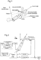
- the invention relates to a method and a device for piloting control of a powered vehicle which is provided with orientation control means, in particular a launcher provided with steerable nozzles.
- the axis of the vehicle is coincident with one of the axes of the reference mark.
- the control is a control loop whose primary purpose is to stabilize the movements of the launcher around its center of gravity (concept of stability), typically by adjusting the thrust orientation.
- the steering achieves as much as possible the attitude setpoint sent by the guidance (the control is a slave system "follower") and ensures a certain immunity of the launcher face disturbances that it is likely to meet (driving is a regulation loop).
- the steering function from the inertial measurements of attitudes (the same as those used by the guidance), determines the proper orientation of the thrust.
- the wind also generates an overall movement of the launcher (movement in translation or drift). Since the guidance takes into account the current point of the launcher (using inertial measurements) to establish a new trajectory to the target point, it is not wrong to consider only the movements around the center of gravity for the establishment. performance of the steering function.
- the piloting function must take into account certain peculiarities which, in particular, make the launcher, by its very nature, a non-stationary system. Its physical characteristics (position of the center of gravity, mass, inertia) and aerodynamics evolve according to the flight. Transient phases will interact with the piloting function, among which the stage separation, the presence of external (wind) and internal disturbances (eccentricity of the thrust for example). Finally, like any physical system, launcher parameters are affected by uncertainties.
- the control algorithm is usually integrated as recurrent equations in a numerical calculator.
- the guidance algorithm based on the information provided by the detectors (attitudes, attitude speeds, accelerations) and navigation, calculates the attitude instructions to be made by the control loop, and which therefore serve the purpose of piloting algorithm.
- the driving laws are determined by assuming a decoupling of the axes pitch, yaw and roll. This hypothesis makes it possible to synthesize the law using a one-axis model valid for small angles. The effect of the coupling of the three laws (one for each axis) is verified a posteriori in three-axis simulation.
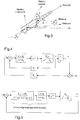
- the figure 2 establishes the one-axis functional diagram of the control law.
- the control algorithm is seen as a "black" box with information from launcher detectors (inertial center for attitude measurement and gyrometer for attitude speed measurement) and defining a command for the one-axis actuator, here a nozzle.
- the one-axis representation assumes that the movement of the thrower is a plane movement.
- the actuator is slaved in position. It rallies a position equivalent to the steering set translated into elongation.
- the main difficulty encountered by the designer of the steering group is the retranscription of the physical objectives that the piloting law must satisfy to deduce a mathematical criterion that can then be optimized. This retranscription requires circumventing the physical nature of the objectives to find an adequate mathematical representation.
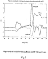
- the stability (from a physical point of view) is noted by the damping quality of the temporal response of the control loop subjected to a disturbance or a setpoint.
- the degree of stability (damping value) is related to the overvoltage coefficient of the control loop (resonance of the control loop at a given frequency).
- the explicit relation between damping and the overvoltage coefficient exists only for so-called academic systems (second-order systems).
- Each algorithm provides synthesis parameters to optimize the law so that it meets the requirements and constraints required for control (stability, retrofit performance, robustness in stability and performance).
- the standard formatting generally generates a complexity of the algorithm.
- the synthesis parameters are not necessarily adapted to the resolution of the problem, one is obliged to give oneself additional degrees of freedom (hence an increase in order) to correctly transcribe the objectives.
- the subject of the invention is a method and a device for controlling an orientable machine, enslaved in attitude on a trajectory and subjected to external disturbances, implementing a control algorithm whose parameters can be correlated with fixed physical objectives. for piloting.
- a control device adapted to the implementation of the method as described above, comprising an input receiving at least one pitch attitude measurement, an output intended to apply a control of an actuator, at least a pitch servo loop connected between this input and this output and comprising a first-order correction filter, a transfer term comprising characteristic parameters of the vehicle and external disturbances, a gain in attitude and a gain in speed of rotation. 'attitude.
- control algorithm strictly necessary in terms of complexity is used to control a machine.
- the algorithm is based on a generic structure whose parameters are computed in a formal way according to those of the vehicle to be piloted and the desired characteristics of the piloting (trajectory tracking, minimization of the incidence, transient phases, ...) .
- the law explicitly takes into account the uncertainties of the gear parameters and a globalized chain delay (delay induced by the dynamics of the actuator + delay of the sensors + delay due to the sampling).
- the synthesis parameters are high-level physical parameters (damping of the closed loop, bandwidth,). We know how to associate with these parameters a physical quantity and a corresponding objective. The adjustment is obtained directly from the physical requirements expressed by the designer.
- the establishment of a pilot law requires the introduction of a launcher model called the synthesis model.
- the uncorrected open loop dynamics can be represented by two coupled equations describing the attitude and drift movements of the launcher (cf. Fig. 3 ).
- the uncorrected open loop dynamics can be represented, with reference to the quantities defined in FIG. figure 3 , by two coupled equations describing the movements of attitude and drift of the craft.
- the pitch moment can be defined by equations (1) of the appendix while the transverse forces with respect to the axis of the air velocity can be defined by equations (2).
- equation (3) which, after derivation with respect to time, gives equations (4).
- condition (C) If we assume that the terms identified in condition (C) are small for the values of this contained in the bandwidth of the control loop, we can approach the expression (5) by the expression (6).
- This expression shows that the system is of order 2 with a first-order dynamics, unstable at the pulsation AT 6 . .
- the system of equations (6) constitutes the model of synthesis from which will be established the bases of the analytical synthesis.
- the pure delay has, in the above expression, been approximated by an approximation of PADE of order 1.
- the loopback is performed so that the corresponding closed loop meets the expected stability and performance objectives.
- the figure 4 shows the generic architecture of the analytic piloting law. It is presented on the assumption that attitude and attitude measurements are accessible but, as will be shown later, this assumption is not a limitation of the method.
- the delay ⁇ sum the chain delay, the delay induced by the sampling-blocking as well as the delay equivalent to the phase shift of the rudder.
- This delay may also include the phase shift of a filter for locally attenuating the loop gain of the driving law to ensure a gain robustness of a launcher soft mode.
- the first dynamics of the closed loop process are evaluated to fix the latter on a model of the 2nd order of parameters ( ⁇ , ⁇ n ).
- This policy makes it possible to condense the performance-stability tradeoff of a elegant way.
- the damping induces a certain degree of stability whereas ⁇ n (speed of the servo-control) generates temporal performances.
- the parameters ( ⁇ , ⁇ n ) thus constitute the setting parameters of "high level".
- the previous method is applicable even if the attitude speed measurement is not accessible.
- the latter is estimated by a clean high-pass type estimator (existence of a direct transmission term at high frequencies) or strictly clean (high-frequency filter gain cutoff with a slope of 20 dB per second). decade at least). Let's choose a high-pass filter with a cutoff of 20 dB per decade. Its expression is defined by equation (12).
- the piloting law then becomes a mono-looping law whose architecture is defined by the figure 5 .
- the expressions of the control law ( ⁇ 1 , ⁇ 2 , K v ) can be entirely determined by development of the closed loop at order 3 and as a function of the parameters K p, ⁇ n, ⁇ , ⁇ c and ⁇ .
- Kp a non-zero value of Kp will have to be set if one wishes a good attitude monitoring (take-off, flight phase out of atmosphere).
- a low or no value of Kp should be chosen to minimize the incidence in critical flight phases such as those corresponding to the maximum dynamic pressure.
- ⁇ n determines the speed of feedback of the control loop.
- the pulsation ⁇ n must be properly selected so that the launcher's retraction at the maximum dynamic pressure is compatible with the permissible incidence and the performance of the servo drive.
- the setting parameter ⁇ n is therefore closely related to the performance objective of the control law.
- the choice of ⁇ n will take into account the uncertainties on the parameters of the launcher (objective of robustness in performance).
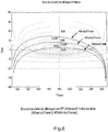
- the stability and stability stability objectives are set by the parameter ⁇ so that all the launchers defined by the variations of the parameters A 6 and K 1 are stabilized with a damping at least equal to the damping specified by the designer. .
- the synthesis process is reiterated for n flight points of the stage considered.
- the non stationary global law is obtained by interpolating the n stationary laws.
- the analytic law has two basic generic forms depending on whether or not attitude feedback is given by equations (13) and (14).
- a first proposition consists in making one or the other of the basic forms more complex by multiplying them by a filter of any order.
- This filter will have the objectives of either locally reducing the gain in order to avoid exciting soft modes of the launcher at particular frequencies, or to provide a gain attenuation of the loop from a certain frequency defined by the designer.
- the pulse ⁇ 1 is equal to AT 6 , the launcher's own dynamics. This is compensated for. More precisely, it can be written that the pulsation ⁇ 1 is proportional to the dynamic pressure of the moment of flight considered and inversely proportional to the inertia of the launcher. Its value is a difficult to quantify, since it depends on the characteristics of the launcher.
- ⁇ 2 depends on the speed chosen for the control loop. In the same way as before, it is difficult to give a range of numerical values. However, qualitatively, we can specify that the greater the value of ⁇ 2 , the faster the control loop will be. In practice, the speed of the loop is chosen such that the latter does not force the process (launcher) beyond its own dynamics AT 6 .
- the expression of the gain K v is relatively complex.
- damping ⁇ parameter setting the stability and stability stability of the control loop.
- the degree of stability of the control is all the more important that the numerical value of the gain K v is high, the latter being proportional to ⁇ .
- ⁇ n 3.5 rad / s
- the synthesis step of the corrector is repeated until a value of ⁇ n compatible with the steering performance verified by time simulation is found.
- the analytical piloting law makes it possible to reach quickly the objectives of stability and performance for all the launchers described by the variations of the parameters A6 and K1. Unlike the LQG or H ⁇ type methods, frequency iteration, which consists in checking the stability margins afterwards, has been eliminated. The temporal iteration, which makes it possible to choose the speed of the control loop, remains necessary because the objective of performance is directly related to the nature of the disturbances acting on the launcher (wind, gust, internal disturbances, ). The non-stationary extension is direct and does not pose particular problems from the point of view of synthesis.
- the analytical piloting law may possibly be extended for machines other than launchers.
- the basic study shows that it is elaborated from a synthesis model deduced from the equations of the mechanics of flight, the strong hypothesis being the instability of the machine.
- this type of law is therefore no limitation for this type of law to be applicable for unstable aircraft on one or more axes of flight (pitch, yaw and roll). For that, it is enough to adapt the equations of the mechanics of the flight to the unstable planes. This adaptation will make it possible to obtain a new synthesis model from which the parameters of the analytical control law will be deduced.
Landscapes
- Engineering & Computer Science (AREA)
- Aviation & Aerospace Engineering (AREA)
- Radar, Positioning & Navigation (AREA)
- Remote Sensing (AREA)
- Physics & Mathematics (AREA)
- General Physics & Mathematics (AREA)
- Automation & Control Theory (AREA)
- Control Of Position, Course, Altitude, Or Attitude Of Moving Bodies (AREA)
- Feedback Control In General (AREA)
Claims (11)
- Verfahren zum Steuern einer angetriebenen Rakete im Flug, welche mit einem verstellbaren Triebwerk versehen ist, welche in einer Haltung auf eine Bahnkurve gezwungen wird und externen Störungen unterworfen ist, wobei wenigstens in Nickrichtung:- zuvor ein Steuergesetz definiert wird, welches einen Korrekturterm erster Ordnung, einen charakteristischen Parameter der Rakete und externe Störungen (A6, K1) umfassenden Transferterm, eine Haltungszunahme (KP) und eine Haltungs-Geschwindigkeitszunahme (KV) umfasst;- zuvor Korrelationsverhältnisse zwischen der Haltungs-Geschwindigkeitszunahme und den Parametern des Korrekturterms als Funktion der Haltungszunahme, den Parametern des Transferterms der Rakete und von zwei Termen definiert werden, welche Sollwerte der Rapidität (ωn) und der Dämpfung (ζ) repräsentieren, und- für wenigstens eine Phase des Flugs der Rakete Werte der Parameter des Transferterms bestimmt werden und die Haltungszunahme und die Terme der Rapidität und der Dämpfung ausgewählt werden, hieraus die Parameter des Korrekturterms und die Geschwindigkeitszunahme abgeleitet werden, und auf das Triebwerk das Steuerungsgesetz mit diesen Werten der Parameter angewendet wird.
- Verfahren nach Anspruch 1, dadurch gekennzeichnet, dass die Korrelationsgesetze ausgehend von einer beschränkten Entwicklung der Gleichung des Regelkreises definiert werden, welcher durch die Rakete und ihr Triebwerk gebildet ist.
- Verfahren nach Anspruch 1 oder 2, dadurch gekennzeichnet, dass für die Phase des Flugs Werte (A6max, K1min) der Parameter des Transferterms bestimmt werden, welche die externen Störungen erhöhen.
- Verfahren nach einem der Ansprüche 1 bis 3, dadurch gekennzeichnet, dass ferner in dem Steuerungsgesetz ein Filter vorgesehen wird.
- Verfahren nach einem der Ansprüche 1 bis 4, dadurch gekennzeichnet, dass das Steuerungsgesetz unter Verwendung von Messungen der Haltung und der Haltungsgeschwindigkeit angewendet wird.
- Verfahren nach einem der Ansprüche 1 bis 4, dadurch gekennzeichnet, dass das Steuerungsgesetz unter Verwendung eines Schätzfilters der Haltungsgeschwindigkeit in dem Steuerungsgesetz angewendet wird.
- Verfahren nach einem der Ansprüche 1 bis 6, dadurch gekennzeichnet, dass ein Validierungstest durch Simulation auf die Auswahlen der Haltungszunahme und die Terme der Rapidität und der Dämpfung während der gesamten Dauer des Flugs angewendet wird, und diese Auswahlen während des gesamten Flugs angewendet werden, wenn die Auswahlen validiert werden, und falls nicht die Flugzeit in mehrere Phasen aufgeteilt wird.
- Verfahren nach einem der Ansprüche 1 bis 7, dadurch gekennzeichnet, dass der Transferterm für externe Störungen definiert wird, welche im Wesentlichen durch atmosphärische Luft hervorgerufen werden.
- Verfahren nach einem der Ansprüche 1 bis 8, dadurch gekennzeichnet, dass das Steuerungsgesetz ferner einen Retardierungsterm umfasst.
- Verfahren nach einem der Ansprüche 1 bis 9, dadurch gekennzeichnet, dass für die Roll- und die Gierrichtung Steuerungsgesetze angewendet werden, welche gemäß demselben Verfahren definiert werden wie das Steuerungsgesetz für die Nickrichtung.
- Steuerungsvorrichtung, welche dazu eingerichtet ist, das Verfahren nach einem der Ansprüche 1 bis 10 durchzuführen, umfassend einen Eingang, welcher wenigstens eine Messung einer Nickhaltung empfängt, einen Ausgang, welcher dazu eingerichtet ist, eine Anweisung eines Triebwerks anzuwenden, wenigstens eine Regelungsschleife für die Nickrichtung, welche zwischen dem Eingang und dem Ausgang verbunden ist und einen Korrekturfilter erster Ordnung umfasst, wobei ein Transferterm einen charakteristischen Parameter der Rakete und externe Störungen, eine Haltungszunahme und eine Haltungs-Geschwindigkeitszunahme umfasst.
Applications Claiming Priority (3)
| Application Number | Priority Date | Filing Date | Title |
|---|---|---|---|
| FR0215588 | 2002-12-10 | ||
| FR0215588A FR2848307B1 (fr) | 2002-12-10 | 2002-12-10 | Procede et dispositif de pilotage d'un engin orientable au moyen d'un actionneur asservi en attitude sur une trajectoire |
| PCT/FR2003/003637 WO2004063824A1 (fr) | 2002-12-10 | 2003-12-09 | Procede et dispositif de pilotage d'un engin orientable au moyen d'un actionneur asservi en attitude sur une trajectoire |
Publications (3)
| Publication Number | Publication Date |
|---|---|
| EP1570326A2 EP1570326A2 (de) | 2005-09-07 |
| EP1570326B1 true EP1570326B1 (de) | 2017-10-25 |
| EP1570326B8 EP1570326B8 (de) | 2017-12-06 |
Family
ID=32320150
Family Applications (1)
| Application Number | Title | Priority Date | Filing Date |
|---|---|---|---|
| EP03815096.7A Expired - Lifetime EP1570326B8 (de) | 2002-12-10 | 2003-12-09 | Verfahren und vorrichtung zur steuerung eines körpers, der mittels einem stellglied schwenkbar und auf eine trajektorie lagegeregelt ist |
Country Status (6)
| Country | Link |
|---|---|
| EP (1) | EP1570326B8 (de) |
| ES (1) | ES2657436T3 (de) |
| FR (1) | FR2848307B1 (de) |
| RU (1) | RU2323464C2 (de) |
| UA (1) | UA82858C2 (de) |
| WO (1) | WO2004063824A1 (de) |
Families Citing this family (8)
| Publication number | Priority date | Publication date | Assignee | Title |
|---|---|---|---|---|
| RU2465535C1 (ru) * | 2011-05-12 | 2012-10-27 | Открытое акционерное общество "Конструкторское бюро приборостроения" | Способ телеуправления ракетой |
| RU2511610C1 (ru) * | 2012-11-13 | 2014-04-10 | Открытое акционерное общество "Конструкторское бюро приборостроения" | Способ формирования сигналов управления вращающейся вокруг продольной оси двухканальной ракетой |
| CN105783612B (zh) * | 2016-03-28 | 2018-01-05 | 北京航天控制仪器研究所 | 一种通用小型化数字电动舵机控制器及其控制方法 |
| RU2663251C1 (ru) * | 2017-05-30 | 2018-08-03 | Акционерное общество Московский научно-производственный комплекс "Авионика" имени О.В. Успенского (АО МНПК "Авионика") | Способ помощи в навигации для уточнения траектории летательного аппарата |
| FR3073282B1 (fr) * | 2017-11-07 | 2020-10-16 | Centre Nat Etd Spatiales | Procede de guidage d'un lanceur spatial le long d'une trajectoire |
| RU2695762C1 (ru) * | 2019-01-25 | 2019-07-25 | Федеральное государственное казённое военное образовательное учреждение высшего образования "Военная академия воздушно-космической обороны имени Маршала Советского Союза Г.К. Жукова" Министерства обороны Российской Федерации | Способ формирования параметров рассогласования в радиоэлектронной системе управления ракетой класса "воздух-воздух" при её самонаведении на самолёт из состава их пары по его функциональному назначению по принципу "ведущий-ведомый" |
| CN111830994B (zh) * | 2020-08-05 | 2022-04-01 | 华侨大学 | 一种轮式移动机器人速度控制方法及系统 |
| CN113064443B (zh) * | 2021-03-08 | 2022-10-11 | 北京理工大学 | 增益在线调整方法及使用其的阻尼回路控制方法 |
Family Cites Families (4)
| Publication number | Priority date | Publication date | Assignee | Title |
|---|---|---|---|---|
| US4659035A (en) * | 1985-01-25 | 1987-04-21 | The United States As Represented By The Secretary Of The Navy | Rate estimation by mixing two independent rate signals |
| US5259569A (en) * | 1992-02-05 | 1993-11-09 | Hughes Missile Systems Company | Roll damper for thrust vector controlled missile |
| RU2099665C1 (ru) * | 1995-06-19 | 1997-12-20 | Военная академия противовоздушной обороны им.маршала Советского Союза Жукова Г.К. | Способ формирования сигнала управления ракетой класса "воздух-воздух" и устройство для его осуществления |
| IL118883A (en) * | 1996-07-17 | 2000-06-01 | Israel State | Flight control of an airborne vehicle at low velocity |
-
2002
- 2002-12-10 FR FR0215588A patent/FR2848307B1/fr not_active Expired - Fee Related
-
2003
- 2003-09-12 UA UAA200506737A patent/UA82858C2/uk unknown
- 2003-12-09 WO PCT/FR2003/003637 patent/WO2004063824A1/fr not_active Ceased
- 2003-12-09 ES ES03815096.7T patent/ES2657436T3/es not_active Expired - Lifetime
- 2003-12-09 EP EP03815096.7A patent/EP1570326B8/de not_active Expired - Lifetime
- 2003-12-09 RU RU2005121574/28A patent/RU2323464C2/ru not_active IP Right Cessation
Non-Patent Citations (1)
| Title |
|---|
| None * |
Also Published As
| Publication number | Publication date |
|---|---|
| ES2657436T3 (es) | 2018-03-05 |
| FR2848307A1 (fr) | 2004-06-11 |
| RU2005121574A (ru) | 2006-02-27 |
| EP1570326A2 (de) | 2005-09-07 |
| EP1570326B8 (de) | 2017-12-06 |
| WO2004063824A1 (fr) | 2004-07-29 |
| UA82858C2 (en) | 2008-05-26 |
| WO2004063824A8 (fr) | 2004-09-23 |
| FR2848307B1 (fr) | 2005-08-26 |
| RU2323464C2 (ru) | 2008-04-27 |
Similar Documents
| Publication | Publication Date | Title |
|---|---|---|
| EP2613214B1 (de) | Steuerungsverfahren einer Drehflügel-Drone, um Aufnahmen mit einer Bordkamera mit Minimierung der störenden Bewegungen zu machen | |
| EP2242552B1 (de) | Verfahren zur führung einer drehflügeldrohne mit automatischer flugstabilisierung im schwebezustand | |
| EP2644240B1 (de) | Flughöhenschätzgerät für Drehflügel-Drohne mit mehreren Rotoren | |
| FR2988868A1 (fr) | Procede de pilotage d'un drone a voilure tournante a rotors multiples avec estimation et compensation du vent lateral | |
| EP2431084A1 (de) | Verfahren zum Steuern einer Drohne mit schwenkbarer Tragfläche und mehreren Rotoren | |
| FR2978588A1 (fr) | Procede et dispositif de gestion optimisee de l'utilisation des becs et des volets, ainsi que du train d'atterrissage d'un aeronef | |
| FR2946161A1 (fr) | Procede d'elaboration continue et adaptative d'une consigne de vitesse pour la tenue d'un rta par un aeronef | |
| EP3379200A2 (de) | Verfahren zum regulieren des korrekturkurses für luftfahrzeug | |
| EP2048475B1 (de) | Verfahren zur Bestimmung der Lage, Position und Geschwindigkeit eines beweglichen Geräts | |
| EP2957871B1 (de) | Verfahren zum vorhersagen einer kurzzeit-flugbahn eines luftfahrzeugs, entsprechendes computerprogramm, entsprechende vorhersagevorrichtung, lenkverfahren und -system und entsprechendes luftfahrzeug | |
| EP2998818A1 (de) | Dynamisches kontrollverfahren beim starten einer drehflügeldrone | |
| EP1570326B1 (de) | Verfahren und vorrichtung zur steuerung eines körpers, der mittels einem stellglied schwenkbar und auf eine trajektorie lagegeregelt ist | |
| FR3022340A1 (fr) | Procede et dispositif de determination d'une consigne de controle d'un aeronef, produit programme d'ordinateur et aeronef associes | |
| FR2994286A1 (fr) | Procede et dispositif d'aide a la gestion du vol d'un aeronef | |
| EP1756620A1 (de) | System zur messung des projizierten turbulenzfallwinds eines luftfahrzeugs | |
| EP3264214A1 (de) | Verfahren zur dynamischen fluglage-konvertierung eines drehflügeldrohne | |
| EP1157254B1 (de) | Vorrichtung mit kreiseln und beschleunigungsaufnehmern zum bestimmen der lagen eines flugzeugs | |
| FR2949576A1 (fr) | Procede d'aide a la gestion d'un vol en vue de tenir une contrainte de temps | |
| EP3281871A1 (de) | Bilderfassungsverfahren für eine starrflügeldrohne, entsprechendes computerprogramm und elektronisches system | |
| EP2653387A1 (de) | Notinstrument für einen Luftfahrzeug | |
| EP0199648A2 (de) | Verfahren und Vorrichtung zur Nutationsdämpfung eines Satelliten durch Steuerung der Gewichtslagebestimmung | |
| FR2916868A1 (fr) | Procede et dispositif de determination de la marge de stabilite dynamique d'un avion. | |
| EP0678732B1 (de) | Verfahren und Vorrichtung zum Kalibrieren der Kreiseln eines dreiachsenstabilisierten Satelliten | |
| WO2021239696A1 (fr) | Procédé et système d'aide à l'approche d'un aéronef en vue de l'atterrissage | |
| EP1312998B1 (de) | Verfahren und Vorrichtung zur Echtzeitbestimmung des Verhaltens eines Fahrzeugs, insbesondere eines Flugzeuges |
Legal Events
| Date | Code | Title | Description |
|---|---|---|---|
| PUAI | Public reference made under article 153(3) epc to a published international application that has entered the european phase |
Free format text: ORIGINAL CODE: 0009012 |
|
| 17P | Request for examination filed |
Effective date: 20050608 |
|
| AK | Designated contracting states |
Kind code of ref document: A2 Designated state(s): AT BE BG CH CY CZ DE DK EE ES FI FR GB GR HU IE IT LI LU MC NL PT RO SE SI SK TR |
|
| AX | Request for extension of the european patent |
Extension state: AL LT LV MK |
|
| DAX | Request for extension of the european patent (deleted) | ||
| RBV | Designated contracting states (corrected) |
Designated state(s): DE ES GB IT |
|
| RAP1 | Party data changed (applicant data changed or rights of an application transferred) |
Owner name: ASTRIUM SAS |
|
| 17Q | First examination report despatched |
Effective date: 20140923 |
|
| RAP1 | Party data changed (applicant data changed or rights of an application transferred) |
Owner name: AIRBUS DEFENCE AND SPACE SAS |
|
| RAP1 | Party data changed (applicant data changed or rights of an application transferred) |
Owner name: AIRBUS SAFRAN LAUNCHERS SAS |
|
| GRAP | Despatch of communication of intention to grant a patent |
Free format text: ORIGINAL CODE: EPIDOSNIGR1 |
|
| INTG | Intention to grant announced |
Effective date: 20170518 |
|
| RIN1 | Information on inventor provided before grant (corrected) |
Inventor name: MARTINEZ, DIDIER |
|
| GRAS | Grant fee paid |
Free format text: ORIGINAL CODE: EPIDOSNIGR3 |
|
| GRAA | (expected) grant |
Free format text: ORIGINAL CODE: 0009210 |
|
| AK | Designated contracting states |
Kind code of ref document: B1 Designated state(s): DE ES GB IT |
|
| REG | Reference to a national code |
Ref country code: GB Ref legal event code: FG4D Free format text: NOT ENGLISH Ref country code: DE Ref legal event code: R081 Ref document number: 60350721 Country of ref document: DE Owner name: ARIANEGROUP SAS, FR Free format text: FORMER OWNER: EADS SPACE TRANSPORTATION S.A., PARIS, FR |
|
| RAP2 | Party data changed (patent owner data changed or rights of a patent transferred) |
Owner name: ARIANEGROUP SAS |
|
| REG | Reference to a national code |
Ref country code: DE Ref legal event code: R096 Ref document number: 60350721 Country of ref document: DE |
|
| REG | Reference to a national code |
Ref country code: DE Ref legal event code: R081 Ref document number: 60350721 Country of ref document: DE Owner name: ARIANEGROUP SAS, FR Free format text: FORMER OWNER: AIRBUS SAFRAN LAUNCHERS SAS, PARIS, FR |
|
| REG | Reference to a national code |
Ref country code: ES Ref legal event code: FG2A Ref document number: 2657436 Country of ref document: ES Kind code of ref document: T3 Effective date: 20180305 |
|
| REG | Reference to a national code |
Ref country code: DE Ref legal event code: R097 Ref document number: 60350721 Country of ref document: DE |
|
| PLBE | No opposition filed within time limit |
Free format text: ORIGINAL CODE: 0009261 |
|
| STAA | Information on the status of an ep patent application or granted ep patent |
Free format text: STATUS: NO OPPOSITION FILED WITHIN TIME LIMIT |
|
| 26N | No opposition filed |
Effective date: 20180726 |
|
| PGFP | Annual fee paid to national office [announced via postgrant information from national office to epo] |
Ref country code: DE Payment date: 20191216 Year of fee payment: 17 |
|
| PGFP | Annual fee paid to national office [announced via postgrant information from national office to epo] |
Ref country code: IT Payment date: 20191218 Year of fee payment: 17 |
|
| PGFP | Annual fee paid to national office [announced via postgrant information from national office to epo] |
Ref country code: GB Payment date: 20191220 Year of fee payment: 17 Ref country code: ES Payment date: 20200124 Year of fee payment: 17 |
|
| REG | Reference to a national code |
Ref country code: DE Ref legal event code: R119 Ref document number: 60350721 Country of ref document: DE |
|
| GBPC | Gb: european patent ceased through non-payment of renewal fee |
Effective date: 20201209 |
|
| PG25 | Lapsed in a contracting state [announced via postgrant information from national office to epo] |
Ref country code: IT Free format text: LAPSE BECAUSE OF NON-PAYMENT OF DUE FEES Effective date: 20201209 |
|
| PG25 | Lapsed in a contracting state [announced via postgrant information from national office to epo] |
Ref country code: GB Free format text: LAPSE BECAUSE OF NON-PAYMENT OF DUE FEES Effective date: 20201209 Ref country code: DE Free format text: LAPSE BECAUSE OF NON-PAYMENT OF DUE FEES Effective date: 20210701 |
|
| REG | Reference to a national code |
Ref country code: ES Ref legal event code: FD2A Effective date: 20220208 |
|
| PG25 | Lapsed in a contracting state [announced via postgrant information from national office to epo] |
Ref country code: ES Free format text: LAPSE BECAUSE OF NON-PAYMENT OF DUE FEES Effective date: 20201210 |