EP1157254B1 - Vorrichtung mit kreiseln und beschleunigungsaufnehmern zum bestimmen der lagen eines flugzeugs - Google Patents
Vorrichtung mit kreiseln und beschleunigungsaufnehmern zum bestimmen der lagen eines flugzeugs Download PDFInfo
- Publication number
- EP1157254B1 EP1157254B1 EP00902695A EP00902695A EP1157254B1 EP 1157254 B1 EP1157254 B1 EP 1157254B1 EP 00902695 A EP00902695 A EP 00902695A EP 00902695 A EP00902695 A EP 00902695A EP 1157254 B1 EP1157254 B1 EP 1157254B1
- Authority
- EP
- European Patent Office
- Prior art keywords
- vector
- aerodyne
- gyrometric
- accelerometers
- loop
- Prior art date
- Legal status (The legal status is an assumption and is not a legal conclusion. Google has not performed a legal analysis and makes no representation as to the accuracy of the status listed.)
- Expired - Lifetime
Links
Images


Classifications
-
- G—PHYSICS
- G01—MEASURING; TESTING
- G01C—MEASURING DISTANCES, LEVELS OR BEARINGS; SURVEYING; NAVIGATION; GYROSCOPIC INSTRUMENTS; PHOTOGRAMMETRY OR VIDEOGRAMMETRY
- G01C21/00—Navigation; Navigational instruments not provided for in groups G01C1/00 - G01C19/00
- G01C21/10—Navigation; Navigational instruments not provided for in groups G01C1/00 - G01C19/00 by using measurements of speed or acceleration
- G01C21/12—Navigation; Navigational instruments not provided for in groups G01C1/00 - G01C19/00 by using measurements of speed or acceleration executed aboard the object being navigated; Dead reckoning
- G01C21/16—Navigation; Navigational instruments not provided for in groups G01C1/00 - G01C19/00 by using measurements of speed or acceleration executed aboard the object being navigated; Dead reckoning by integrating acceleration or speed, i.e. inertial navigation
- G01C21/183—Compensation of inertial measurements, e.g. for temperature effects
- G01C21/188—Compensation of inertial measurements, e.g. for temperature effects for accumulated errors, e.g. by coupling inertial systems with absolute positioning systems
-
- G—PHYSICS
- G01—MEASURING; TESTING
- G01C—MEASURING DISTANCES, LEVELS OR BEARINGS; SURVEYING; NAVIGATION; GYROSCOPIC INSTRUMENTS; PHOTOGRAMMETRY OR VIDEOGRAMMETRY
- G01C21/00—Navigation; Navigational instruments not provided for in groups G01C1/00 - G01C19/00
- G01C21/10—Navigation; Navigational instruments not provided for in groups G01C1/00 - G01C19/00 by using measurements of speed or acceleration
- G01C21/12—Navigation; Navigational instruments not provided for in groups G01C1/00 - G01C19/00 by using measurements of speed or acceleration executed aboard the object being navigated; Dead reckoning
- G01C21/16—Navigation; Navigational instruments not provided for in groups G01C1/00 - G01C19/00 by using measurements of speed or acceleration executed aboard the object being navigated; Dead reckoning by integrating acceleration or speed, i.e. inertial navigation
- G01C21/183—Compensation of inertial measurements, e.g. for temperature effects
- G01C21/185—Compensation of inertial measurements, e.g. for temperature effects for gravity
Definitions
- the invention relates to a determination apparatus attitudes of a flying machine.
- Attitudes are by definition the three angles Euler ⁇ , ⁇ , ⁇ , or, respectively, heading, attitude, and inclination, which define the orientation of the marker linked to the aerodyne compared to the local geographical reference.
- the landmark (or trihedron) local geographical area is an orthonormal trihedron whose axis is following the local vertical (down) and the other two axes along the north and east directions.
- the reference linked to the aerodyne is an orthonormed trihedron whose axis X, or axis of roll, is collinear with the fuselage of the aerodyne, the Y axis, or pitch axis, is perpendicular to its plane of symmetry, and the Z axis, or yaw axis, is included in the plane of symmetry.
- Attitudes are determined using a so-called linked-component gyrometric device consisting of at least three gyrometers integral with each other and integral with the structure of the aircraft. Each of these provides a component, along its axis, of the vector ⁇ instantaneous rotation of the aircraft compared to an inertial reference system.
- This device makes it possible to measure the three components of ⁇ in the X, Y, Z coordinate linked to the aerodyne. These components are, respectively, the roll p along the X axis, the pitch q along the Y axis and the yaw r along the Z axis.
- Integration provides quaternions of attitudes, from which one deduces, with the initial orientation of the aerodyne, a matrix of attitudes then the angles Euler.
- the measurement signals delivered by the gyrometers defects called drifts. Since these signals are integrated, attitude errors increase with the time. That's why, usually, to determine attitudes, in addition to gyrometers, accelerometers are used which are used to correct the results provided by the integration of gyrometer signals. This correction is made in a servo loop.
- Accelerometers integral with the gyrometric device linked components can provide, thanks to gravity, attitude in attitude and inclination of the aerodyne; however the signals they deliver are tainted with errors that make the results difficult to use as they are.
- the combination, in a servo loop, of signals provided by gyrometers and accelerometers allows to compensate the drifts of the gyrometers while maintaining the advantage of these which is to provide results with a relatively low noise in the short term.
- the comparison between gyrometric and accelerometric signals constitutes an operation complex because the signals of the accelerometers are integrated in order to represent speeds and these are compared to references; this comparison serves to develop the correction of the gyrometric device. Integration uses to the attitudes resulting from the gyrometric device.
- US-A-4,070,674 discloses a apparatus conforming to the preamble of this claim 1.
- the invention provides an apparatus in which the corrections are performed simply and reliably.
- the comparison is made between, on the one hand, a vector of vertical direction provided by the gyrometric device and, on the other hand, a vertical direction vector provided by accelerometers.
- the comparison consists of performing the vector product of these two vectors.
- the vertical direction vector provided by the accelerometers is collinear with the acceleration of gravity, during the non-accelerated straight flight phases. So, he it is not necessary to integrate the signals accelerometer. Moreover, in the gyrometric device, the vertical direction vector is the last column of the attitude matrix obtained with this device. In in addition, the two vertical direction vectors can be expressed in the same reference frame linked to the aerodyne.
- the attitude matrix is a 3x3 matrix in which the first column represents the north direction in the XYZ mark of the aerodyne, and the second and third columns respectively represent the east and vertical directions, also in XYZ mark.
- vector product is isotropic, that is to say independent of the reference.
- the vector product module is proportional to the sine of the angle of the rotation that makes the direction vector coincide vertical provided by the gyrometric device with the vector vertical direction provided by the accelerometer device.
- the direction of the vector product gives the axis of this rotation.
- a vector product being, by definition, perpendicular to each of the product's vectors, its component is zero in the vertical direction, and if we want to estimate the vertical component of the drift of the gyrometric device, additional data is needed.
- an orthogonal projection of the vector is performed. ⁇ of components p, qr, which is provided by the gyrometers, after compensation of the drifts (by the servocontrol mentioned above), on the vertical direction provided by the gyrometric device.
- U g represents the drift of the gyrometer in the vertical direction only if the airplane is in straight flight phase, that is to say that it does not turn around the vertical direction.
- the turning phases are detected and the lace servo loop (to compensate for the vertical component of the drifts of the device) is opened during the turning phases.
- the accelerometer device does not provide a vector representing the acceleration of gravity that during the phases of straight flight not accelerated. So it is better to open at least some servo loops of the gyrometric device during the turning and / or acceleration phases. We open the roll control loop in the turning phases and we open the servo loop of pitch during the acceleration phases. During turns accelerated, the roll loop is preferably opened, the loop of pitch remaining closed.
- a enslavement in cape that is to say that we enslave the direction from the north, expressed as an aerodyne mark, provided by the device gyrometric, magnetic north provided by a sensor external such as a magnetometer.
- the heading deviation is represented by a vector whose direction corresponds to the vertical of the gyrometric device so that it does not conflict with the vector product mentioned above which, by definition, is perpendicular to the vertical direction provided by the gyro device.
- a vector U m representing the direction of magnetic north (provided by a magnetometer)
- a vector b 1 representing the north direction provided by the gyrometric device in the first column of the attitude matrix.
- This vector product is then projected on the vertical direction b 3 provided by the gyrometric device.
- the invention thus provides a determination apparatus of attitudes, including the attitude and inclination of an aerodyne according to claim 1.
- attitude and inclination of an aerodyne according to claim 1.
- the embodiment of the invention that we are going describe in relation to the figures relates to an instrument or aircraft to determine the attitudes of an airplane that includes at least three gyrometers (not shown) whose components have a fixed position relative to the aircraft.
- the device gyrometric is, under these conditions, said to "components
- gyrometers are sensors whose axes have well-defined positions in relation to the axes of the plane.
- the apparatus also includes accelerometers (not shown) to correct errors or drifts of the gyrometers.
- accelerometers not shown
- accelerometers are used which give the components of the acceleration of the aerodyne corresponding to the resultant of the contact forces applying to this aircraft.
- Contact forces means thrust and aerodynamic forces (drag and lift). AT from these components provided by the accelerometers, can deduce the acceleration of gravity, that is to say the vertical direction. Indeed :
- F d is the sum of the so-called "remote" forces that apply to the aerodyne, that is, gravity and inertia, F it is the sum of the contact forces mentioned above, ⁇ it is the kinematic acceleration of the aerodyne and m the mass of the latter.
- the forces of inertia are the forces of Coriolis which are here negligible.
- the accelerometers then provide the components of the acceleration boy Wut of gravity.
- the components of boy Wut are determined with respect to the axes of the sensors that constitute the accelerometers. Since these sensors are attached to the aircraft frame, it is easy to determine the components of the boy Wut in the reference of the plane.
- the accelerometers therefore provide an indication of the orientation of the aircraft.
- accelerometers do not provide a vector component boy Wut than during uniform straight flight phases of the aircraft. In other phases, we can know the vertical direction, provided we have other data, as will be seen later.
- a servo loop is provided in which the vector ⁇ provided by the gyrometers is integrated to provide the attitudes. Accelerations are integrated using gyrometric attitudes to make marker change projections and the resulting velocities are compared to a reference to derive the corrections that are used to correct the gyro data in a closed loop.
- the invention consists in directly comparing the vertical direction vector provided by the accelerometers to the vertical direction vector provided by the matrix of attitudes that the gyrometric device delivers.
- the apparatus according to the invention is therefore particularly simple because, on the one hand, it is not necessary to integrate the data provided by the accelerometers and, on the other hand, the vectors U a and U g are in the same reference which is that of the sensors, that is to say the housing 10.
- the vector ⁇ is exploitable to perform the correction since its norm is sin ⁇ , where ⁇ is the angle between the vectors U g and U a .
- the correction is to rotate the vector U g of an angle ⁇ so as to bring it back in the direction of the vector U a .
- This vector ⁇ in a servo loop that converges the vector U g to the vector U a . This convergence occurs with a rotation speed equal to the norm of the vector ⁇ and therefore proportional (if the angle ⁇ is small) to the angular difference between the vectors U g and U a .
- the correction is isotropic, that is to say independent of the reference in which one is. However, will perform the servo calculations in the sensor mark.
- the vector U g is provided by the last column of the attitude matrix of the gyrometric device.
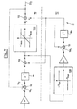
- This servocontrol circuit comprises: an integrating calculation means, or integrator 12, providing a quaternion of attitudes, a means 14 for extracting the matrix B of quaternion attitudes, and a block 16 that extracts matrix B the last column that represents the vector U g , that is to say the unit vector of vertical direction in the XYZ mark of the housing 10.
- the vector U g provided by block 16 is applied to the first input of a block 18 of vector product whose second input receives the vertical unit vector U provided by the accelerometric device.
- the block 18 delivers on its output the vector ⁇ .
- a first proportional control loop comprising an amplifier (or attenuator) 20 of coefficient k 1 .
- This proportional slaving is completed by an integrator servo 22 making it possible to estimate and compensate for the drifts of the gyrometric device.
- a second loop is thus provided with a second amplifier (or attenuator) 24 of coefficient k 2 .
- the signal of the first loop is provided on a first input - (minus) of a subtractor 26 whose output is connected to the input of the integrator 12 and which has a + input (plus) 28 receiving the vector ⁇ g provided by the three gyrometers and a second input - 30 connected to the output of the integrator 22 in series with the amplifier 24.
- switches are provided, respectively 32 and 34, which are open during the phases dynamic flight. Indeed, during these phases, the accelerometers no longer provide the components of the acceleration of gravity. However, during these openings loops enslavement, we continue to compensate for the drifts of the gyrometers thanks to the output of the integrator 22.
- each arrow line represents vector information of dimension 3. There is therefore, in practice, three servo loops, one for each component. The most appropriate reference is the (X, Y, Z) linked to the aerodyne.
- FIG. 3 will now describe a servocontrol circuit which uses control loops similar to those shown in FIG. 2 and, in addition, another servocontrol loop enabling the vertical component of the servocontrol to be compensated for. drift d ⁇ g .
- the vertical component of the instantaneous rotation constituting the rate of turn serves to distinguish the straight phases of the phases of turns to open, at correctly chosen times, some of the loops. servo.
- an orthogonal projection of the vector is carried out ⁇ c , that is to say the instantaneous rotation vector compensated for the estimated drifts, on the direction U g .
- the dot product is produced ⁇ c . U g , and we use the vector ( ⁇ c . U g ). U g to perform lace control.
- the vector ⁇ g is applied to the input + of a subtractor 40 whose output is connected to the input + of another subtractor 42 whose input - receives the output of the amplifier 20 (k 1 ). Moreover, the input - of the subtractor 40 is connected to the output of an adder 44 via the integrator 22.
- a first input of the adder 44 is connected to the output of the amplifier 24 (k 2 ), whereas the second input of this adder is connected to the output of a gain amplifier 46 k 3 located in the loop lace servo.
- This lace servo loop comprises a block 48 which calculates the components of the vector ( ⁇ c . U g ). U g .
- this block 48 has an input 50 receiving the vector ⁇ c ( ⁇ g compensated drifts, due to the servo loop amplifier 24 and integrator 22), and a second input 52 receiving the vector U g provided by the output of the block 16.
- the output of the block 48 is connected to the input of the amplifier 46 via a switch 54.
- the servo amplifier loop 46 Since the servo amplifier loop 46 must compensate a drift, it includes an integrator, and the latter is the integrator 22, which also makes part of the amplifier loop 24.
- U g represents the vertical component of the drift of the gyrometric device provided that the aircraft does not rotate around the vertical. This is why the switch 54 is open during turns.
- This switch 32 must be open during accelerations or turns, because, in this case, the vector U provided by the accelerometers does not represent the actual vertical direction. To detect these phases, the angular differences between the vectors are detected.
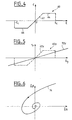
- FIG. 4 is a diagram showing, for a component (x for example), the variation of the correction c range ordinate of the amplifier 20 as a function of the component ⁇ x of the vector ⁇ , this component ⁇ x being plotted on the abscissa.
- This variation is represented by a line 60 having: a linear zone of slope K 1 represented by a line segment 62 passing through the origin O, saturation zones represented by line segments 64 and 66 parallel to the axis of the lines abscissae, and cutoff areas beyond the abscissa ⁇ xc and - ⁇ xc .
- the saturation limits the signal applied to the input - of the subtractor 42. This limit of the signal corresponds to the maximum allowable for the compensation of the drifts. Such a feature is a compromise between a proportional correction and the open loop. This saturation feature mitigates the effect of errors in ⁇ on the accuracy of U g , without having to cut off the enslavement.
- the standards of ⁇ and of ⁇ c at thresholds to detect the evolutions of the aerodyne, when passing into phase of turn or acceleration.
- Switch 54 is open when the rate of turn exceeds a threshold. This rate of turn is represented by the scalar product ⁇ c . U g .
- This arrangement is to maintain the switch 32 closed y from the time the switch 32 x is open, regardless ⁇ y, by replacing, in this case, the amplifier profile 20 are as described with Figure 4 by that described with Figure 5, that is to say with a lower slope and continuous without threshold.
- the gain of the amplifier k 1y 20 presents a lower value during the turning phases.
- the ⁇ y component of the vector is plotted on the abscissa. ⁇ , and, on the ordinate, the signal r y at the output of the amplifier 20 y .
- the line 60 y represented in broken lines corresponds to the line 60 of FIG. 4.
- This variation of r y as a function of ⁇ y occurs during the straight-flight phases without acceleration, the switch 32 x of the roll control loop. being closed in this case.
- the switch 32 x is opened and the switch 32 remains closed.
- line 72 is the characteristic of the amplifier 20 is changed in this situation: the slope of the line 72 is less than the slope of the line 62 there.
- the maintaining in the open or closed state of the switches 32 depends on the comparison of each component of ⁇ at a threshold.
- ⁇ c . U g which represents the rate of turn.
- the opening of 32 x is forbidden when ⁇ x exceeds its cut-off threshold if the calculated turn ratio indicates that it is not turning.
- the profile of the amplifier 20 y as shown in FIG. 4 is replaced by a linear profile such as the line 72 in FIG. 5. However, the slope of this line is greater than the slope of the line 62.
- the integrator 22 must be able to compensate the open-loop drifts, that is to say when the servocontrols are inhibited.
- Integrator 22 takes into account the characteristics of drifts of the gyrometric device. In particular, evolution drifts as a function of time being limited by a slope characteristic of the gyrometers, the output slope of the integrator 22.
- FIG. 7 shows a sampled system, of period dt.
- Each block Z -1 is a delay, which means that the output is one period behind the input.
- the integrator 22 comprises two stages, respectively 90 and 92.
- the first stage comprises a delay 94 whose input is connected to the output of an adder 96, an input 96 1 of which constitutes the input of the integrator 22 and whose other input 96 2 is connected to the output 22 2 of the integrator 22.
- the output of the delay 94 is connected to the input + of a subtracter 98 whose output is connected to the input of a difference saturator 100 limiting the signals between two values + E max and -E max of opposite signs .
- the output of the saturator 100 is connected to an input of an adder 102 whose output is connected to the output 22 2 of the integrator 22.
- the second stage 92 also comprises a delay 104 whose output is connected to the second input of the adder 102 and whose input is connected to the output of an adder 106, an input 106 1 of which is connected to the output of a slope saturator 108 whose input is connected to the output of the subtractor 98 upstream of the difference saturator 100.
- the output of delay 104 is also connected to the input - of the subtracter 98, and the second input of the adder 106.
- the slope saturator 108 makes it possible to limit the slope of the second stage 92 to two maximum slopes of opposite signs P max , -P max .
- the first stage 90 directly integrates the signal input. Its output is limited by the saturator 100 in a fixed width zone whose center is the output signal of the second floor 92.
- the output signal of the second stage evolves according to two opposite maximum slopes P max and -P max determined by the saturator 108.
- the second stage 92 serves to limit the average slope of the integrated signal, while the output of the integrator 22 is provided by the first floor.
- the evolution of the output signal is shown in FIG. 8. It can be seen that the output signal 105 is confined between two broken lines 107 and 109 whose all segments are parallel to each other. Each of the segments of lines 107 and 109 alternately having a slope P max and a slope -P max . As long as the difference between the signals of the two stages 90 and 92 remains smaller than the maximum difference 2E max (parts 110, 112, etc. of the curve 105), the estimator has a linear operation, that is to say that he functions as a simple integrator. The dynamic properties of the servocontrol around the zero value are thus preserved.
- the integrator 22 shown in FIG. allows to limit the average speed of evolution of the estimation signal and not to limit the instantaneous speed of this signal estimation. These characteristics make it possible to overcome difficulties that could result from theft with many turns and therefore with frequent opening of servo loops.
- the vectors V and ⁇ as well as the acceleration dV / dt are considered aerodyne reference.
- the speed of the aerodyne, V can be determined by an anemometer.
- the aerodyne reference speed is a vector V whose component V x is the velocity provided by the anemometer and the components V y and V z are zero (since there is no slip and the incidence is zero).
- An anemometer can be used to maintain constantly closed the servo loops, either to limit the opening periods of these loops.
- One embodiment of this provision of the invention is to provide a course correction vector. ⁇ c vertical direction so that this correction does not conflict with that provided by the vector ⁇ mentioned above which is by construction, in the horizontal plane (vector product of the vertical directions provided by the gyrometric device and by the accelerometers).
- the vector U m is the unit vector in the magnetic north direction and b 1 , b 2 and b 3 are the three vectors provided by each of the three columns of the attitudinal matrix B with:
- the vector b 1 is the attitude vector in the north direction
- the vector b 2 is the attitude vector in the east direction
- the vector b 3 is the attitude vector in the vertical direction.
- Equation (5) means that the vector product of U m by b 1 and project the result vector to the vertical given by b 3 .
- FIG. 9 represents, in a simplified manner, the control loops used in this embodiment where a heading correction is performed.
- This FIG. 9 is similar to that of FIG. 3.
- the lace servo is replaced by the cap servo.
- the integrator 22 is common to the attitude and heading servo loops.
- Block 120 represents the organ that determines the vectors ⁇ c deviation of attitudes (obtained from the vector product of the vertical direction vectors provided, on the one hand, by the gyrometric device and, on the other hand, by the accelerometers) and ⁇ c of course deviation.
- This vector ⁇ it is obtained from the attitude matrix and the vector B Earth's magnetic field.
- a correction of the proportional type with a gain ⁇ (amplifier 122) and a correction of integral type of gain ⁇ (amplifier 124) is provided in the servo-control in captivity, the latter correction using the same integrator 22 as the servo-control. in attitude of gain k 2 .
- the apparatus comprises, typically, reset means usually referred to as "caging".
- This reset is triggered manually by the pilot to converge quickly attitudes so that the vertical direction determined by the gyrometric device corresponds to the vertical real.
- This function can be used in flight at speed rectilinear constant, or in any phase of flight, if the data provided by an anemometer, or the like, are combined with the data provided by the accelerometers.
- the gains of the amplifiers proportional servo loops are increased for a specified time, for example three minutes, on the three axes and, during this period, the control loops are kept in the closed state and the saturations are inhibited. Since the integrators are flanged, the control loops enable to quickly converge the errors of attitudes so that they can get into the catching range of these servos.
Claims (19)
- Gerät zur Bestimmung von Fluglagen, insbesondere der Trimmlage () und der Neigung (Φ) eines Luftfahrzeugs, das aufweist:dadurch gekennzeichnet, dass die Beschleunigungsmesser fest mit der gyrometrischen Vorrichtung verbunden sind, und dass der Vergleich zwischen dem von der gyrometrischen Vorrichtung gelieferten senkrechten Richtungsvektoreine gyrometrische Vorrichtung mit verbundenen Komponenten, die mindestens drei Gyrometer aufweist und die Komponenten des augenblicklichen Drehvektors (
Ω ) des Luftfahrzeugs in einem mit dem Luftfahrzeug verbundenen Bezugssystem liefert,Mittel, um ausgehend von gyrometrischen Messungen eine Fluglagenmatrix (b 1,b 2,b 3) zu berechnen, die die Orientierung des Luftfahrzeugs bezüglich des lokalen geographischen Bezugssystems definiert, einschließlich insbesondere der Komponenten eines senkrechten RichtungsvektorsU g in einem mit dem Luftfahrzeug verbundenen Bezugssystem,Beschleunigungsmesser, die die Komponenten eines VektorsU a liefern, der die Richtung der Senkrechten in einem mit dem Luftfahrzeug verbundenen Bezugssystem darstellt, wenn das Luftfahrzeug sich in einer nicht beschleunigten, geradlinigen Bewegung fortbewegt,Mittel, um ausgehend von den Beschleunigungsmessern berechnete Daten mit Daten zu vergleichen, die ausgehend von den Gyrometern berechnet werden, um Korrekturen zur Kompensation der Fehler oder Drifte der gyrometrischen Vorrichtung zu liefern,U g und dem von den Beschleunigungsmessern gelieferten senkrechten RichtungsvektorU a durchgeführt und ein den Unterschied zwischen diesen Richtungen darstellendes Fehlersignal erstellt wird. - Gerät nach Anspruch 1, dadurch gekennzeichnet, dass die Komponenten des von der gyrometrischen Vorrichtung gelieferten Vektors
U a aus der letzten Spalte (b 3) der Fluglagenmatrix bestehen. - Gerät nach einem der vorhergehenden Ansprüche, dadurch gekennzeichnet, dass die senkrechten Richtungsvektoren eine Einheitslänge haben.
- Gerät nach einem der vorhergehenden Ansprüche, dadurch gekennzeichnet, dass die Vergleichsmittel das Vektorprodukt (
ε ) der beiden senkrechten Richtungsvektoren herstellen. - Gerät nach einem der vorhergehenden Ansprüche, dadurch gekennzeichnet, dass es eine Regelschleife vom proportionalen Typ aufweist.
- Gerät nach Anspruch 5, dadurch gekennzeichnet, dass die Regelschleife vom proportionalen Typ eine Verstärkung aufweist, die auf einen vorbestimmten maximalen Wert (64, 66) begrenzt ist.
- Gerät nach einem der vorhergehenden Ansprüche, dadurch gekennzeichnet, dass es eine Regelschleife mit Integrator (22) aufweist, um die Drifte zu kompensieren.
- Gerät nach Anspruch 4, dadurch gekennzeichnet, dass es ein Mittel aufweist, um eine Korrektur gemäß der senkrechten Richtung durchzuführen.
- Gerät nach Anspruch 8, dadurch gekennzeichnet, dass das Mittel zur Durchführung einer Korrektur gemäß der senkrechten Richtung ein Mittel zur Berechnung der Projektion des von der gyrometrischen Vorrichtung gelieferten augenblicklichen Drehvektors (
Ω ) auf die senkrechte Richtung aufweist, wobei die senkrechte Richtung, auf die die Projektion durchgeführt wird, von der gyrometrischen Vorrichtung geliefert wird, und der augenblickliche Drehvektor, der projiziert wird, von der Regelschleife korrigiert wird. - Gerät nach einem der vorhergehenden Ansprüche, dadurch gekennzeichnet, dass der senkrechte Richtungsvektor einerseits von den Beschleunigungsmessern und andererseits ausgehend von der Geschwindigkeit des Luftfahrzeugs geliefert wird, die zum Beispiel von Windmessungsmitteln geliefert wird.
- Gerät nach Anspruch 10, dadurch gekennzeichnet, dass die senkrechte Richtung ausgehend von der folgenden Gleichung bestimmt wird:
F d die Schwerkraft in senkrechter Richtung,V der von den Windmessungsmitteln bestimmte Geschwindigkeitsvektor des Luftfahrzeugs,Ω der durch die gyrometrische Vorrichtung bestimmte augenblickliche Drehvektor des Luftfahrzeugs,F c die von den Beschleunigungsmessern bestimmte Resultierende der Kontaktkräfte, und m die Masse des Luftfahrzeugs ist. - Gerät nach einem der vorhergehenden Ansprüche,
dadurch gekennzeichnet, dass es ein Mittel zur Regelung des gyrometrischen Kurses auf den magnetischen Kurs aufweist. - Gerät nach den Ansprüchen 4 und 12, dadurch gekennzeichnet, dass die Regelung des Kurses ausgehend vom Korrekturvektor (
ε c) bestimmt wird, der die folgende Gleichung erfüllt:U m ein Vektor ist, der die Richtung des magnetischen Nordens darstellt, vorzugsweise mit einer Einheitsamplitude, und die Vektorenb 1,b 2 undb 3 drei Vektoren sind, deren Koordinaten von den Spalten der Fluglagenmatrix geliefert werden, die von der gyrometrischen Vorrichtung geliefert wird. - Gerät nach einem der vorhergehenden Ansprüche, dadurch gekennzeichnet, dass es geschlossene Regelschleifen der Fluglagen, die die von den Vergleichsmitteln gelieferten Korrektursignale verwenden, und Mittel aufweist, um mindestens eine Schleife außerhalb der Phasen des geradlinigen Flugs mit konstanter Geschwindigkeit des Luftfahrzeugs zu öffnen.
- Gerät nach Anspruch 14, dadurch gekennzeichnet, dass das Öffnen der Regelschleifen erfolgt, wenn der Unterschied zwischen dem von der gyrometrischen Vorrichtung gelieferten senkrechten Richtungsvektor und dem von den Beschleunigungsmessern gelieferten senkrechten Richtungsvektor einen vorbestimmten Wert (εxc) überschreitet.
- Gerät nach Anspruch 14 oder 15, dadurch gekennzeichnet, dass wenn eine Roll-Regelschleife während einer Kurve offen ist, eine entsprechende Nick-Regelschleife während dieser Kurve geschlossen bleibt.
- Gerät nach einem der Ansprüche 14 bis 16, dadurch gekennzeichnet, dass, wenn der Kurvengrad verwendet wird, um zwischen den Phasen des geradlinigen Flugs und anderen Flugphasen zu unterscheiden, eine Roll-Regelschleife geschlossen ist, wenn der Kurvengrad im Absolutwert unter einem bestimmten Schwellwert liegt.
- Gerät nach den Ansprüchen 7 und 8, dadurch gekennzeichnet, dass es eine Regelschleife aufweist, um eine Korrektur der gyrometrischen Messungen in senkrechter Richtung zu gewährleisten, und dass diese Regelschleife gemeinsam mit der die Drifte kompensierenden Schleife einen Integrator (22) aufweist.
- Gerät nach Anspruch 18, dadurch gekennzeichnet, dass der Integrator (22) Mittel (108), die es ermöglichen, die mittlere Steigung seines Ausgangssignals zu begrenzen, und Mittel (100) aufweist, damit zu jedem Zeitpunkt das Ausgangssignal einen unter einer Schwelle liegenden Unterschied im Vergleich mit einem Signal mit linearer Veränderung mit bestimmter Neigung aufweist.
Applications Claiming Priority (3)
| Application Number | Priority Date | Filing Date | Title |
|---|---|---|---|
| FR9901181 | 1999-02-02 | ||
| FR9901181A FR2789172B1 (fr) | 1999-02-02 | 1999-02-02 | Appareil a gyrometres et accelerometres pour la determination des attitudes d'un aerodyne |
| PCT/FR2000/000219 WO2000046573A1 (fr) | 1999-02-02 | 2000-01-31 | Appareil a gyrometres et accelerometres pour la determination des attitudes d'un aerodyne |
Publications (2)
| Publication Number | Publication Date |
|---|---|
| EP1157254A1 EP1157254A1 (de) | 2001-11-28 |
| EP1157254B1 true EP1157254B1 (de) | 2005-03-16 |
Family
ID=9541507
Family Applications (1)
| Application Number | Title | Priority Date | Filing Date |
|---|---|---|---|
| EP00902695A Expired - Lifetime EP1157254B1 (de) | 1999-02-02 | 2000-01-31 | Vorrichtung mit kreiseln und beschleunigungsaufnehmern zum bestimmen der lagen eines flugzeugs |
Country Status (8)
| Country | Link |
|---|---|
| US (1) | US6588117B1 (de) |
| EP (1) | EP1157254B1 (de) |
| JP (1) | JP4447791B2 (de) |
| BR (1) | BR0007735A (de) |
| CA (1) | CA2361727A1 (de) |
| DE (1) | DE60018719T2 (de) |
| FR (1) | FR2789172B1 (de) |
| WO (1) | WO2000046573A1 (de) |
Families Citing this family (18)
| Publication number | Priority date | Publication date | Assignee | Title |
|---|---|---|---|---|
| DE10115217C1 (de) * | 2001-03-28 | 2002-08-14 | Bosch Gmbh Robert | Verfahren zum Bestimmen der Winkellage eines Fahrzeugs |
| FR2833714B1 (fr) * | 2001-12-18 | 2004-04-02 | Thales Sa | Procede de traitement d'un signal de navigation contenant des donnees |
| FR2834144B1 (fr) * | 2001-12-20 | 2004-02-27 | Thales Sa | Convertisseur et convertisseur inverse (moyenne, ecart), correcteur de boucle, recepteur et procede de reception bi-frequence associe les utilisant |
| FR2837638B1 (fr) * | 2002-03-22 | 2006-07-14 | Thales Sa | Procede de traitement de signal en presence d'interferences |
| FR2841069B1 (fr) * | 2002-06-14 | 2004-10-22 | Thales Sa | Recepteur de positionnement par satellite utilisant deux porteuses de signal |
| FR2843638B1 (fr) * | 2002-08-13 | 2004-10-22 | Thales Sa | Recepteur de positionnement par satellite avec correction d'erreurs d'inter-correlation |
| FR2869997B1 (fr) * | 2004-05-04 | 2006-06-23 | Commissariat Energie Atomique | Accelerometre en boucle fermee avec detection d'erreur |
| FR2871313B1 (fr) * | 2004-06-08 | 2006-08-18 | Thales Sa | Procede de transmission d'un signal de radionavigation |
| FR2895073B1 (fr) * | 2005-12-20 | 2008-02-08 | Thales Sa | Dispositif d'hybridation en boucle fermee avec surveillance de l'integrite des mesures. |
| KR100711261B1 (ko) * | 2006-06-21 | 2007-04-25 | (주)마이크로인피니티 | 입력 장치의 공간 인식 방법 및 그 장치 |
| US8184974B2 (en) | 2006-09-11 | 2012-05-22 | Lumexis Corporation | Fiber-to-the-seat (FTTS) fiber distribution system |
| SE531778C2 (sv) * | 2007-01-09 | 2009-08-04 | C2Sat Comm Ab | Förfarande för att driftkompensera ett positionsmätningsorgan |
| US8326561B2 (en) * | 2008-05-20 | 2012-12-04 | Airmar Technology Corporation | Dynamic motion control |
| JP5596145B2 (ja) | 2009-08-06 | 2014-09-24 | ルメクシス・コーポレーション | 直列ネットワーキングファイバーツーザシート機内エンターテイメントシステム |
| US8424045B2 (en) | 2009-08-14 | 2013-04-16 | Lumexis Corporation | Video display unit docking assembly for fiber-to-the-screen inflight entertainment system |
| WO2011022708A1 (en) | 2009-08-20 | 2011-02-24 | Lumexis Corp. | Serial networking fiber optic inflight entertainment system network configuration |
| US9383384B2 (en) * | 2013-05-31 | 2016-07-05 | Honeywell International Inc. | Extended-range closed-loop accelerometer |
| US20220234700A1 (en) * | 2019-08-16 | 2022-07-28 | WP Controls, LLC | Boat lift systems and methods |
Family Cites Families (9)
| Publication number | Priority date | Publication date | Assignee | Title |
|---|---|---|---|---|
| US3597598A (en) * | 1964-12-14 | 1971-08-03 | North American Rockwell | Method and means for transforming the acceleration signals generated by accelerometers in a first coordinate system into acceleration signals in a second coordinate system |
| US3974699A (en) * | 1973-08-28 | 1976-08-17 | Systron Donner Corporation | Angular position sensing and control system, apparatus and method |
| US4070674A (en) * | 1973-10-17 | 1978-01-24 | The Singer Company | Doppler heading attitude reference system |
| US3979090A (en) * | 1975-03-17 | 1976-09-07 | Sperry Rand Corporation | Velocity damped erection system for stable gyroscopic attitude and heading reference apparatus |
| US4179818A (en) * | 1976-10-07 | 1979-12-25 | Litton Systems, Inc. | Tetrahedral redundant inertial reference unit |
| FR2511146B1 (fr) * | 1981-08-07 | 1986-07-25 | British Aerospace | Instrument de navigation |
| DE3634023A1 (de) * | 1986-10-07 | 1988-04-21 | Bodenseewerk Geraetetech | Integriertes, redundantes referenzsystem fuer die flugregelung und zur erzeugung von kurs- und lageinformationen |
| US5297052A (en) * | 1989-10-16 | 1994-03-22 | The Boeing Company | Integrated fault-tolerant air data inertial reference system |
| US5479161A (en) * | 1994-03-25 | 1995-12-26 | Honeywell Inc. | Automatic calibration of redundant sensors |
-
1999
- 1999-02-02 FR FR9901181A patent/FR2789172B1/fr not_active Expired - Fee Related
-
2000
- 2000-01-31 WO PCT/FR2000/000219 patent/WO2000046573A1/fr active IP Right Grant
- 2000-01-31 EP EP00902695A patent/EP1157254B1/de not_active Expired - Lifetime
- 2000-01-31 JP JP2000597607A patent/JP4447791B2/ja not_active Expired - Fee Related
- 2000-01-31 DE DE60018719T patent/DE60018719T2/de not_active Expired - Fee Related
- 2000-01-31 CA CA002361727A patent/CA2361727A1/fr not_active Abandoned
- 2000-01-31 BR BR0007735-6A patent/BR0007735A/pt not_active IP Right Cessation
- 2000-01-31 US US09/889,578 patent/US6588117B1/en not_active Expired - Fee Related
Also Published As
| Publication number | Publication date |
|---|---|
| CA2361727A1 (fr) | 2000-08-10 |
| US6588117B1 (en) | 2003-07-08 |
| JP2002538033A (ja) | 2002-11-12 |
| DE60018719D1 (de) | 2005-04-21 |
| WO2000046573A1 (fr) | 2000-08-10 |
| FR2789172A1 (fr) | 2000-08-04 |
| BR0007735A (pt) | 2002-01-29 |
| DE60018719T2 (de) | 2006-04-13 |
| JP4447791B2 (ja) | 2010-04-07 |
| FR2789172B1 (fr) | 2001-04-13 |
| EP1157254A1 (de) | 2001-11-28 |
Similar Documents
| Publication | Publication Date | Title |
|---|---|---|
| EP1157254B1 (de) | Vorrichtung mit kreiseln und beschleunigungsaufnehmern zum bestimmen der lagen eines flugzeugs | |
| WO2013144508A1 (fr) | Procede de pilotage d'un drone a voilure tournante a rotors multiples avec estimation et compensation du vent lateral et du biais des accelerometres. | |
| EP2048475B1 (de) | Verfahren zur Bestimmung der Lage, Position und Geschwindigkeit eines beweglichen Geräts | |
| EP2644240B1 (de) | Flughöhenschätzgerät für Drehflügel-Drohne mit mehreren Rotoren | |
| US8442703B2 (en) | Turning-stabilized estimation of the attitude angles of an aircraft | |
| EP2400460B1 (de) | Bewertungsverfahren der horizontalen Geschwindigkeit einer Drohne, insbesondere einer Drohne mit über den Autopiloten gesteuertem stationärem Flug | |
| EP0493143A1 (de) | System zur Lagestabilisierung eines dreiachs-stabilisierten Satelliten, insbesondere eines Beobachtungssatelliten | |
| EP2169508B1 (de) | Geschosssteuerungssystem | |
| EP2998818A1 (de) | Dynamisches kontrollverfahren beim starten einer drehflügeldrone | |
| EP2613213A1 (de) | Intuitives Steuerungsverfahren einer Drone mit Hilfe eines Fernbedienungsgeräts | |
| FR2915569A1 (fr) | Procede de calibration d'un capteur | |
| WO2012152669A1 (fr) | Dispositif et procede de determination d'attitude d'un satellite, et satellite embarquant un tel dispositif | |
| EP1205732A2 (de) | Inertialnavigationseinheit mit integriertem GPS-Empfänger | |
| EP3896398B1 (de) | Verfahren zur identifizierung einer statischen phase eines fahrzeugs | |
| EP0292339B1 (de) | Integriertes Lagebestimmungssystem für Flugzeuge | |
| FR2697651A1 (fr) | Procédé et appareil de calibration des gyromètres d'un satellite stabilisé 3-axes. | |
| WO2004063824A1 (fr) | Procede et dispositif de pilotage d'un engin orientable au moyen d'un actionneur asservi en attitude sur une trajectoire | |
| FR2926637A1 (fr) | Procede et dispositif pour l'estimation de la vitesse par rapport a l'air d'un vehicule aerien | |
| WO2023094763A1 (fr) | Procédé de limitation de correction de vitesse baro-inertielle et système associé | |
| EP0671323A1 (de) | Adaptives Lagerregelungsverfahren für magnetische Stabilisierung eines Satelliten bezüglich der Roll- und der Gierachse | |
| EP3983759B1 (de) | Verfahren zur überwachung der leistung von trägheitsmesseinheiten | |
| WO2023094761A1 (fr) | Procédé de détection de défaillance d'un baro-altimètre dans une boucle baro-inertielle et système associé | |
| FR2759163A1 (fr) | Dispositif de determination des vitesses angulaires d'un aeronef |
Legal Events
| Date | Code | Title | Description |
|---|---|---|---|
| PUAI | Public reference made under article 153(3) epc to a published international application that has entered the european phase |
Free format text: ORIGINAL CODE: 0009012 |
|
| 17P | Request for examination filed |
Effective date: 20010828 |
|
| AK | Designated contracting states |
Kind code of ref document: A1 Designated state(s): AT BE CH CY DE DK ES FI FR GB GR IE IT LI LU MC NL PT SE |
|
| RBV | Designated contracting states (corrected) |
Designated state(s): DE FR GB |
|
| GRAP | Despatch of communication of intention to grant a patent |
Free format text: ORIGINAL CODE: EPIDOSNIGR1 |
|
| GRAS | Grant fee paid |
Free format text: ORIGINAL CODE: EPIDOSNIGR3 |
|
| GRAA | (expected) grant |
Free format text: ORIGINAL CODE: 0009210 |
|
| AK | Designated contracting states |
Kind code of ref document: B1 Designated state(s): DE FR GB |
|
| REG | Reference to a national code |
Ref country code: GB Ref legal event code: FG4D Free format text: NOT ENGLISH |
|
| REG | Reference to a national code |
Ref country code: IE Ref legal event code: FG4D Free format text: FRENCH |
|
| REF | Corresponds to: |
Ref document number: 60018719 Country of ref document: DE Date of ref document: 20050421 Kind code of ref document: P |
|
| GBT | Gb: translation of ep patent filed (gb section 77(6)(a)/1977) |
Effective date: 20050405 |
|
| PLBE | No opposition filed within time limit |
Free format text: ORIGINAL CODE: 0009261 |
|
| STAA | Information on the status of an ep patent application or granted ep patent |
Free format text: STATUS: NO OPPOSITION FILED WITHIN TIME LIMIT |
|
| 26N | No opposition filed |
Effective date: 20051219 |
|
| PG25 | Lapsed in a contracting state [announced via postgrant information from national office to epo] |
Ref country code: DE Free format text: LAPSE BECAUSE OF NON-PAYMENT OF DUE FEES Effective date: 20060801 |
|
| REG | Reference to a national code |
Ref country code: FR Ref legal event code: PLFP Year of fee payment: 17 |
|
| REG | Reference to a national code |
Ref country code: FR Ref legal event code: PLFP Year of fee payment: 18 |
|
| REG | Reference to a national code |
Ref country code: FR Ref legal event code: PLFP Year of fee payment: 19 |
|
| PGFP | Annual fee paid to national office [announced via postgrant information from national office to epo] |
Ref country code: GB Payment date: 20180123 Year of fee payment: 19 |
|
| PGFP | Annual fee paid to national office [announced via postgrant information from national office to epo] |
Ref country code: FR Payment date: 20181227 Year of fee payment: 20 |
|
| GBPC | Gb: european patent ceased through non-payment of renewal fee |
Effective date: 20190131 |
|
| PG25 | Lapsed in a contracting state [announced via postgrant information from national office to epo] |
Ref country code: GB Free format text: LAPSE BECAUSE OF NON-PAYMENT OF DUE FEES Effective date: 20190131 |