EP1157254B1 - Apparatus with gyroscopes and accelerometers for determining the attitudes of an aerodyne - Google Patents
Apparatus with gyroscopes and accelerometers for determining the attitudes of an aerodyne Download PDFInfo
- Publication number
- EP1157254B1 EP1157254B1 EP00902695A EP00902695A EP1157254B1 EP 1157254 B1 EP1157254 B1 EP 1157254B1 EP 00902695 A EP00902695 A EP 00902695A EP 00902695 A EP00902695 A EP 00902695A EP 1157254 B1 EP1157254 B1 EP 1157254B1
- Authority
- EP
- European Patent Office
- Prior art keywords
- vector
- aerodyne
- gyrometric
- accelerometers
- loop
- Prior art date
- Legal status (The legal status is an assumption and is not a legal conclusion. Google has not performed a legal analysis and makes no representation as to the accuracy of the status listed.)
- Expired - Lifetime
Links
Images


Classifications
-
- G—PHYSICS
- G01—MEASURING; TESTING
- G01C—MEASURING DISTANCES, LEVELS OR BEARINGS; SURVEYING; NAVIGATION; GYROSCOPIC INSTRUMENTS; PHOTOGRAMMETRY OR VIDEOGRAMMETRY
- G01C21/00—Navigation; Navigational instruments not provided for in groups G01C1/00 - G01C19/00
- G01C21/10—Navigation; Navigational instruments not provided for in groups G01C1/00 - G01C19/00 by using measurements of speed or acceleration
- G01C21/12—Navigation; Navigational instruments not provided for in groups G01C1/00 - G01C19/00 by using measurements of speed or acceleration executed aboard the object being navigated; Dead reckoning
- G01C21/16—Navigation; Navigational instruments not provided for in groups G01C1/00 - G01C19/00 by using measurements of speed or acceleration executed aboard the object being navigated; Dead reckoning by integrating acceleration or speed, i.e. inertial navigation
- G01C21/183—Compensation of inertial measurements, e.g. for temperature effects
- G01C21/188—Compensation of inertial measurements, e.g. for temperature effects for accumulated errors, e.g. by coupling inertial systems with absolute positioning systems
-
- G—PHYSICS
- G01—MEASURING; TESTING
- G01C—MEASURING DISTANCES, LEVELS OR BEARINGS; SURVEYING; NAVIGATION; GYROSCOPIC INSTRUMENTS; PHOTOGRAMMETRY OR VIDEOGRAMMETRY
- G01C21/00—Navigation; Navigational instruments not provided for in groups G01C1/00 - G01C19/00
- G01C21/10—Navigation; Navigational instruments not provided for in groups G01C1/00 - G01C19/00 by using measurements of speed or acceleration
- G01C21/12—Navigation; Navigational instruments not provided for in groups G01C1/00 - G01C19/00 by using measurements of speed or acceleration executed aboard the object being navigated; Dead reckoning
- G01C21/16—Navigation; Navigational instruments not provided for in groups G01C1/00 - G01C19/00 by using measurements of speed or acceleration executed aboard the object being navigated; Dead reckoning by integrating acceleration or speed, i.e. inertial navigation
- G01C21/183—Compensation of inertial measurements, e.g. for temperature effects
- G01C21/185—Compensation of inertial measurements, e.g. for temperature effects for gravity
Definitions
- the invention relates to a determination apparatus attitudes of a flying machine.
- Attitudes are by definition the three angles Euler ⁇ , ⁇ , ⁇ , or, respectively, heading, attitude, and inclination, which define the orientation of the marker linked to the aerodyne compared to the local geographical reference.
- the landmark (or trihedron) local geographical area is an orthonormal trihedron whose axis is following the local vertical (down) and the other two axes along the north and east directions.
- the reference linked to the aerodyne is an orthonormed trihedron whose axis X, or axis of roll, is collinear with the fuselage of the aerodyne, the Y axis, or pitch axis, is perpendicular to its plane of symmetry, and the Z axis, or yaw axis, is included in the plane of symmetry.
- Attitudes are determined using a so-called linked-component gyrometric device consisting of at least three gyrometers integral with each other and integral with the structure of the aircraft. Each of these provides a component, along its axis, of the vector ⁇ instantaneous rotation of the aircraft compared to an inertial reference system.
- This device makes it possible to measure the three components of ⁇ in the X, Y, Z coordinate linked to the aerodyne. These components are, respectively, the roll p along the X axis, the pitch q along the Y axis and the yaw r along the Z axis.
- Integration provides quaternions of attitudes, from which one deduces, with the initial orientation of the aerodyne, a matrix of attitudes then the angles Euler.
- the measurement signals delivered by the gyrometers defects called drifts. Since these signals are integrated, attitude errors increase with the time. That's why, usually, to determine attitudes, in addition to gyrometers, accelerometers are used which are used to correct the results provided by the integration of gyrometer signals. This correction is made in a servo loop.
- Accelerometers integral with the gyrometric device linked components can provide, thanks to gravity, attitude in attitude and inclination of the aerodyne; however the signals they deliver are tainted with errors that make the results difficult to use as they are.
- the combination, in a servo loop, of signals provided by gyrometers and accelerometers allows to compensate the drifts of the gyrometers while maintaining the advantage of these which is to provide results with a relatively low noise in the short term.
- the comparison between gyrometric and accelerometric signals constitutes an operation complex because the signals of the accelerometers are integrated in order to represent speeds and these are compared to references; this comparison serves to develop the correction of the gyrometric device. Integration uses to the attitudes resulting from the gyrometric device.
- US-A-4,070,674 discloses a apparatus conforming to the preamble of this claim 1.
- the invention provides an apparatus in which the corrections are performed simply and reliably.
- the comparison is made between, on the one hand, a vector of vertical direction provided by the gyrometric device and, on the other hand, a vertical direction vector provided by accelerometers.
- the comparison consists of performing the vector product of these two vectors.
- the vertical direction vector provided by the accelerometers is collinear with the acceleration of gravity, during the non-accelerated straight flight phases. So, he it is not necessary to integrate the signals accelerometer. Moreover, in the gyrometric device, the vertical direction vector is the last column of the attitude matrix obtained with this device. In in addition, the two vertical direction vectors can be expressed in the same reference frame linked to the aerodyne.
- the attitude matrix is a 3x3 matrix in which the first column represents the north direction in the XYZ mark of the aerodyne, and the second and third columns respectively represent the east and vertical directions, also in XYZ mark.
- vector product is isotropic, that is to say independent of the reference.
- the vector product module is proportional to the sine of the angle of the rotation that makes the direction vector coincide vertical provided by the gyrometric device with the vector vertical direction provided by the accelerometer device.
- the direction of the vector product gives the axis of this rotation.
- a vector product being, by definition, perpendicular to each of the product's vectors, its component is zero in the vertical direction, and if we want to estimate the vertical component of the drift of the gyrometric device, additional data is needed.
- an orthogonal projection of the vector is performed. ⁇ of components p, qr, which is provided by the gyrometers, after compensation of the drifts (by the servocontrol mentioned above), on the vertical direction provided by the gyrometric device.
- U g represents the drift of the gyrometer in the vertical direction only if the airplane is in straight flight phase, that is to say that it does not turn around the vertical direction.
- the turning phases are detected and the lace servo loop (to compensate for the vertical component of the drifts of the device) is opened during the turning phases.
- the accelerometer device does not provide a vector representing the acceleration of gravity that during the phases of straight flight not accelerated. So it is better to open at least some servo loops of the gyrometric device during the turning and / or acceleration phases. We open the roll control loop in the turning phases and we open the servo loop of pitch during the acceleration phases. During turns accelerated, the roll loop is preferably opened, the loop of pitch remaining closed.
- a enslavement in cape that is to say that we enslave the direction from the north, expressed as an aerodyne mark, provided by the device gyrometric, magnetic north provided by a sensor external such as a magnetometer.
- the heading deviation is represented by a vector whose direction corresponds to the vertical of the gyrometric device so that it does not conflict with the vector product mentioned above which, by definition, is perpendicular to the vertical direction provided by the gyro device.
- a vector U m representing the direction of magnetic north (provided by a magnetometer)
- a vector b 1 representing the north direction provided by the gyrometric device in the first column of the attitude matrix.
- This vector product is then projected on the vertical direction b 3 provided by the gyrometric device.
- the invention thus provides a determination apparatus of attitudes, including the attitude and inclination of an aerodyne according to claim 1.
- attitude and inclination of an aerodyne according to claim 1.
- the embodiment of the invention that we are going describe in relation to the figures relates to an instrument or aircraft to determine the attitudes of an airplane that includes at least three gyrometers (not shown) whose components have a fixed position relative to the aircraft.
- the device gyrometric is, under these conditions, said to "components
- gyrometers are sensors whose axes have well-defined positions in relation to the axes of the plane.
- the apparatus also includes accelerometers (not shown) to correct errors or drifts of the gyrometers.
- accelerometers not shown
- accelerometers are used which give the components of the acceleration of the aerodyne corresponding to the resultant of the contact forces applying to this aircraft.
- Contact forces means thrust and aerodynamic forces (drag and lift). AT from these components provided by the accelerometers, can deduce the acceleration of gravity, that is to say the vertical direction. Indeed :
- F d is the sum of the so-called "remote" forces that apply to the aerodyne, that is, gravity and inertia, F it is the sum of the contact forces mentioned above, ⁇ it is the kinematic acceleration of the aerodyne and m the mass of the latter.
- the forces of inertia are the forces of Coriolis which are here negligible.
- the accelerometers then provide the components of the acceleration boy Wut of gravity.
- the components of boy Wut are determined with respect to the axes of the sensors that constitute the accelerometers. Since these sensors are attached to the aircraft frame, it is easy to determine the components of the boy Wut in the reference of the plane.
- the accelerometers therefore provide an indication of the orientation of the aircraft.
- accelerometers do not provide a vector component boy Wut than during uniform straight flight phases of the aircraft. In other phases, we can know the vertical direction, provided we have other data, as will be seen later.
- a servo loop is provided in which the vector ⁇ provided by the gyrometers is integrated to provide the attitudes. Accelerations are integrated using gyrometric attitudes to make marker change projections and the resulting velocities are compared to a reference to derive the corrections that are used to correct the gyro data in a closed loop.
- the invention consists in directly comparing the vertical direction vector provided by the accelerometers to the vertical direction vector provided by the matrix of attitudes that the gyrometric device delivers.
- the apparatus according to the invention is therefore particularly simple because, on the one hand, it is not necessary to integrate the data provided by the accelerometers and, on the other hand, the vectors U a and U g are in the same reference which is that of the sensors, that is to say the housing 10.
- the vector ⁇ is exploitable to perform the correction since its norm is sin ⁇ , where ⁇ is the angle between the vectors U g and U a .
- the correction is to rotate the vector U g of an angle ⁇ so as to bring it back in the direction of the vector U a .
- This vector ⁇ in a servo loop that converges the vector U g to the vector U a . This convergence occurs with a rotation speed equal to the norm of the vector ⁇ and therefore proportional (if the angle ⁇ is small) to the angular difference between the vectors U g and U a .
- the correction is isotropic, that is to say independent of the reference in which one is. However, will perform the servo calculations in the sensor mark.
- the vector U g is provided by the last column of the attitude matrix of the gyrometric device.
- This servocontrol circuit comprises: an integrating calculation means, or integrator 12, providing a quaternion of attitudes, a means 14 for extracting the matrix B of quaternion attitudes, and a block 16 that extracts matrix B the last column that represents the vector U g , that is to say the unit vector of vertical direction in the XYZ mark of the housing 10.
- the vector U g provided by block 16 is applied to the first input of a block 18 of vector product whose second input receives the vertical unit vector U provided by the accelerometric device.
- the block 18 delivers on its output the vector ⁇ .
- a first proportional control loop comprising an amplifier (or attenuator) 20 of coefficient k 1 .
- This proportional slaving is completed by an integrator servo 22 making it possible to estimate and compensate for the drifts of the gyrometric device.
- a second loop is thus provided with a second amplifier (or attenuator) 24 of coefficient k 2 .
- the signal of the first loop is provided on a first input - (minus) of a subtractor 26 whose output is connected to the input of the integrator 12 and which has a + input (plus) 28 receiving the vector ⁇ g provided by the three gyrometers and a second input - 30 connected to the output of the integrator 22 in series with the amplifier 24.
- switches are provided, respectively 32 and 34, which are open during the phases dynamic flight. Indeed, during these phases, the accelerometers no longer provide the components of the acceleration of gravity. However, during these openings loops enslavement, we continue to compensate for the drifts of the gyrometers thanks to the output of the integrator 22.
- each arrow line represents vector information of dimension 3. There is therefore, in practice, three servo loops, one for each component. The most appropriate reference is the (X, Y, Z) linked to the aerodyne.
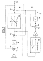
- FIG. 3 will now describe a servocontrol circuit which uses control loops similar to those shown in FIG. 2 and, in addition, another servocontrol loop enabling the vertical component of the servocontrol to be compensated for. drift d ⁇ g .
- the vertical component of the instantaneous rotation constituting the rate of turn serves to distinguish the straight phases of the phases of turns to open, at correctly chosen times, some of the loops. servo.
- an orthogonal projection of the vector is carried out ⁇ c , that is to say the instantaneous rotation vector compensated for the estimated drifts, on the direction U g .
- the dot product is produced ⁇ c . U g , and we use the vector ( ⁇ c . U g ). U g to perform lace control.
- the vector ⁇ g is applied to the input + of a subtractor 40 whose output is connected to the input + of another subtractor 42 whose input - receives the output of the amplifier 20 (k 1 ). Moreover, the input - of the subtractor 40 is connected to the output of an adder 44 via the integrator 22.
- a first input of the adder 44 is connected to the output of the amplifier 24 (k 2 ), whereas the second input of this adder is connected to the output of a gain amplifier 46 k 3 located in the loop lace servo.
- This lace servo loop comprises a block 48 which calculates the components of the vector ( ⁇ c . U g ). U g .
- this block 48 has an input 50 receiving the vector ⁇ c ( ⁇ g compensated drifts, due to the servo loop amplifier 24 and integrator 22), and a second input 52 receiving the vector U g provided by the output of the block 16.
- the output of the block 48 is connected to the input of the amplifier 46 via a switch 54.
- the servo amplifier loop 46 Since the servo amplifier loop 46 must compensate a drift, it includes an integrator, and the latter is the integrator 22, which also makes part of the amplifier loop 24.
- U g represents the vertical component of the drift of the gyrometric device provided that the aircraft does not rotate around the vertical. This is why the switch 54 is open during turns.
- This switch 32 must be open during accelerations or turns, because, in this case, the vector U provided by the accelerometers does not represent the actual vertical direction. To detect these phases, the angular differences between the vectors are detected.
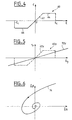
- FIG. 4 is a diagram showing, for a component (x for example), the variation of the correction c range ordinate of the amplifier 20 as a function of the component ⁇ x of the vector ⁇ , this component ⁇ x being plotted on the abscissa.
- This variation is represented by a line 60 having: a linear zone of slope K 1 represented by a line segment 62 passing through the origin O, saturation zones represented by line segments 64 and 66 parallel to the axis of the lines abscissae, and cutoff areas beyond the abscissa ⁇ xc and - ⁇ xc .
- the saturation limits the signal applied to the input - of the subtractor 42. This limit of the signal corresponds to the maximum allowable for the compensation of the drifts. Such a feature is a compromise between a proportional correction and the open loop. This saturation feature mitigates the effect of errors in ⁇ on the accuracy of U g , without having to cut off the enslavement.
- the standards of ⁇ and of ⁇ c at thresholds to detect the evolutions of the aerodyne, when passing into phase of turn or acceleration.
- Switch 54 is open when the rate of turn exceeds a threshold. This rate of turn is represented by the scalar product ⁇ c . U g .
- This arrangement is to maintain the switch 32 closed y from the time the switch 32 x is open, regardless ⁇ y, by replacing, in this case, the amplifier profile 20 are as described with Figure 4 by that described with Figure 5, that is to say with a lower slope and continuous without threshold.
- the gain of the amplifier k 1y 20 presents a lower value during the turning phases.
- the ⁇ y component of the vector is plotted on the abscissa. ⁇ , and, on the ordinate, the signal r y at the output of the amplifier 20 y .
- the line 60 y represented in broken lines corresponds to the line 60 of FIG. 4.
- This variation of r y as a function of ⁇ y occurs during the straight-flight phases without acceleration, the switch 32 x of the roll control loop. being closed in this case.
- the switch 32 x is opened and the switch 32 remains closed.
- line 72 is the characteristic of the amplifier 20 is changed in this situation: the slope of the line 72 is less than the slope of the line 62 there.
- the maintaining in the open or closed state of the switches 32 depends on the comparison of each component of ⁇ at a threshold.
- ⁇ c . U g which represents the rate of turn.
- the opening of 32 x is forbidden when ⁇ x exceeds its cut-off threshold if the calculated turn ratio indicates that it is not turning.
- the profile of the amplifier 20 y as shown in FIG. 4 is replaced by a linear profile such as the line 72 in FIG. 5. However, the slope of this line is greater than the slope of the line 62.
- the integrator 22 must be able to compensate the open-loop drifts, that is to say when the servocontrols are inhibited.
- Integrator 22 takes into account the characteristics of drifts of the gyrometric device. In particular, evolution drifts as a function of time being limited by a slope characteristic of the gyrometers, the output slope of the integrator 22.
- FIG. 7 shows a sampled system, of period dt.
- Each block Z -1 is a delay, which means that the output is one period behind the input.
- the integrator 22 comprises two stages, respectively 90 and 92.
- the first stage comprises a delay 94 whose input is connected to the output of an adder 96, an input 96 1 of which constitutes the input of the integrator 22 and whose other input 96 2 is connected to the output 22 2 of the integrator 22.
- the output of the delay 94 is connected to the input + of a subtracter 98 whose output is connected to the input of a difference saturator 100 limiting the signals between two values + E max and -E max of opposite signs .
- the output of the saturator 100 is connected to an input of an adder 102 whose output is connected to the output 22 2 of the integrator 22.
- the second stage 92 also comprises a delay 104 whose output is connected to the second input of the adder 102 and whose input is connected to the output of an adder 106, an input 106 1 of which is connected to the output of a slope saturator 108 whose input is connected to the output of the subtractor 98 upstream of the difference saturator 100.
- the output of delay 104 is also connected to the input - of the subtracter 98, and the second input of the adder 106.
- the slope saturator 108 makes it possible to limit the slope of the second stage 92 to two maximum slopes of opposite signs P max , -P max .
- the first stage 90 directly integrates the signal input. Its output is limited by the saturator 100 in a fixed width zone whose center is the output signal of the second floor 92.
- the output signal of the second stage evolves according to two opposite maximum slopes P max and -P max determined by the saturator 108.
- the second stage 92 serves to limit the average slope of the integrated signal, while the output of the integrator 22 is provided by the first floor.
- the evolution of the output signal is shown in FIG. 8. It can be seen that the output signal 105 is confined between two broken lines 107 and 109 whose all segments are parallel to each other. Each of the segments of lines 107 and 109 alternately having a slope P max and a slope -P max . As long as the difference between the signals of the two stages 90 and 92 remains smaller than the maximum difference 2E max (parts 110, 112, etc. of the curve 105), the estimator has a linear operation, that is to say that he functions as a simple integrator. The dynamic properties of the servocontrol around the zero value are thus preserved.
- the integrator 22 shown in FIG. allows to limit the average speed of evolution of the estimation signal and not to limit the instantaneous speed of this signal estimation. These characteristics make it possible to overcome difficulties that could result from theft with many turns and therefore with frequent opening of servo loops.
- the vectors V and ⁇ as well as the acceleration dV / dt are considered aerodyne reference.
- the speed of the aerodyne, V can be determined by an anemometer.
- the aerodyne reference speed is a vector V whose component V x is the velocity provided by the anemometer and the components V y and V z are zero (since there is no slip and the incidence is zero).
- An anemometer can be used to maintain constantly closed the servo loops, either to limit the opening periods of these loops.
- One embodiment of this provision of the invention is to provide a course correction vector. ⁇ c vertical direction so that this correction does not conflict with that provided by the vector ⁇ mentioned above which is by construction, in the horizontal plane (vector product of the vertical directions provided by the gyrometric device and by the accelerometers).
- the vector U m is the unit vector in the magnetic north direction and b 1 , b 2 and b 3 are the three vectors provided by each of the three columns of the attitudinal matrix B with:
- the vector b 1 is the attitude vector in the north direction
- the vector b 2 is the attitude vector in the east direction
- the vector b 3 is the attitude vector in the vertical direction.
- Equation (5) means that the vector product of U m by b 1 and project the result vector to the vertical given by b 3 .
- FIG. 9 represents, in a simplified manner, the control loops used in this embodiment where a heading correction is performed.
- This FIG. 9 is similar to that of FIG. 3.
- the lace servo is replaced by the cap servo.
- the integrator 22 is common to the attitude and heading servo loops.
- Block 120 represents the organ that determines the vectors ⁇ c deviation of attitudes (obtained from the vector product of the vertical direction vectors provided, on the one hand, by the gyrometric device and, on the other hand, by the accelerometers) and ⁇ c of course deviation.
- This vector ⁇ it is obtained from the attitude matrix and the vector B Earth's magnetic field.
- a correction of the proportional type with a gain ⁇ (amplifier 122) and a correction of integral type of gain ⁇ (amplifier 124) is provided in the servo-control in captivity, the latter correction using the same integrator 22 as the servo-control. in attitude of gain k 2 .
- the apparatus comprises, typically, reset means usually referred to as "caging".
- This reset is triggered manually by the pilot to converge quickly attitudes so that the vertical direction determined by the gyrometric device corresponds to the vertical real.
- This function can be used in flight at speed rectilinear constant, or in any phase of flight, if the data provided by an anemometer, or the like, are combined with the data provided by the accelerometers.
- the gains of the amplifiers proportional servo loops are increased for a specified time, for example three minutes, on the three axes and, during this period, the control loops are kept in the closed state and the saturations are inhibited. Since the integrators are flanged, the control loops enable to quickly converge the errors of attitudes so that they can get into the catching range of these servos.
Description
L'invention est relative à un appareil de détermination des attitudes d'un engin volant.The invention relates to a determination apparatus attitudes of a flying machine.
Pour piloter un aérodyne, il est nécessaire de connaítre ses attitudes.To pilot an aerodyne, it is necessary to know his attitudes.
Les attitudes sont par définition les trois angles d'Euler ψ, , ϕ, ou, respectivement, cap, assiette, et inclinaison, qui définissent l'orientation du repère lié à l'aérodyne par rapport au repère géographique local. Le repère (ou trièdre) géographique local est un trièdre orthonormé dont un axe est suivant la verticale locale (vers le bas) et les deux autres axes suivant les directions nord et est locales. Le repère lié à l'aérodyne est un trièdre orthonormé dont l'axe X, ou axe de roulis, est colinéaire au fuselage de l'aérodyne, l'axe Y, ou axe de tangage, est perpendiculaire à son plan de symétrie, et l'axe Z, ou axe de lacet, est inclus dans le plan de symétrie.Attitudes are by definition the three angles Euler ψ, , φ, or, respectively, heading, attitude, and inclination, which define the orientation of the marker linked to the aerodyne compared to the local geographical reference. The landmark (or trihedron) local geographical area is an orthonormal trihedron whose axis is following the local vertical (down) and the other two axes along the north and east directions. The reference linked to the aerodyne is an orthonormed trihedron whose axis X, or axis of roll, is collinear with the fuselage of the aerodyne, the Y axis, or pitch axis, is perpendicular to its plane of symmetry, and the Z axis, or yaw axis, is included in the plane of symmetry.
Les attitudes sont déterminées à l'aide d'un dispositif
gyrométrique dit à composants liés, constitué d'au moins
trois gyromètres solidaires entre eux et solidaires de la structure
de l'aéronef. Chacun de ceux-ci fournit une composante,
suivant son axe, du vecteur
Ces trois composantes sont intégrées, par exemple par la méthode dite des quaternions. L'intégration fournit des quaternions d'attitudes, d'où l'on déduit, avec l'orientation initiale de l'aérodyne, une matrice d'attitudes puis les angles d'Euler.These three components are integrated, for example by the so-called quaternions method. Integration provides quaternions of attitudes, from which one deduces, with the initial orientation of the aerodyne, a matrix of attitudes then the angles Euler.
Les signaux de mesure délivrés par les gyromètres présentent des défauts appelés dérives. Comme ces signaux sont intégrés, les erreurs sur les attitudes augmentent avec le temps. C'est pourquoi, habituellement, pour déterminer les attitudes, on fait appel, en plus des gyromètres, à des accéléromètres qui sont utilisés pour corriger les résultats fournis par l'intégration des signaux des gyromètres. Cette correction s'effectue dans une boucle d'asservissement.The measurement signals delivered by the gyrometers defects called drifts. Since these signals are integrated, attitude errors increase with the time. That's why, usually, to determine attitudes, in addition to gyrometers, accelerometers are used which are used to correct the results provided by the integration of gyrometer signals. This correction is made in a servo loop.
Les accéléromètres solidaires du dispositif gyrométrique à composants liés peuvent fournir, grâce à la pesanteur, les attitudes en assiette et inclinaison de l'aérodyne ; toutefois les signaux qu'ils délivrent sont entachés d'erreurs qui rendent les résultats difficilement exploitables tels quels. Par contre, la combinaison, dans une boucle d'asservissement, des signaux fournis par des gyromètres et des accéléromètres permet de compenser les dérives des gyromètres tout en conservant l'avantage de ces derniers qui est de fournir des résultats avec un bruit relativement faible à court terme.Accelerometers integral with the gyrometric device linked components can provide, thanks to gravity, attitude in attitude and inclination of the aerodyne; however the signals they deliver are tainted with errors that make the results difficult to use as they are. By against, the combination, in a servo loop, of signals provided by gyrometers and accelerometers allows to compensate the drifts of the gyrometers while maintaining the advantage of these which is to provide results with a relatively low noise in the short term.
Dans des appareils connus, la comparaison entre les signaux gyrométriques et accélérométriques constitue une opération complexe car les signaux des accéléromètres sont intégrés de façon à représenter des vitesses et ces dernières sont comparées à des références ; cette comparaison sert à élaborer la correction du dispositif gyrométrique. L'intégration fait appel aux attitudes issues du dispositif gyrométrique.In known devices, the comparison between gyrometric and accelerometric signals constitutes an operation complex because the signals of the accelerometers are integrated in order to represent speeds and these are compared to references; this comparison serves to develop the correction of the gyrometric device. Integration uses to the attitudes resulting from the gyrometric device.
Le document US-A-4 070 674 divulgue un
appareil conforme au préambule de la présente
revendication 1. US-A-4,070,674 discloses a
apparatus conforming to the preamble of this
L'invention fournit un appareil dans lequel les corrections sont effectuées de façon simple et fiable. Dans l'appareil selon l'invention, la comparaison est effectuée entre, d'une part, un vecteur de direction verticale fourni par le dispositif gyrométrique et, d'autre part, un vecteur de direction verticale fourni par les accéléromètres. De préférence, la comparaison consiste à effectuer le produit vectoriel de ces deux vecteurs.The invention provides an apparatus in which the corrections are performed simply and reliably. In the apparatus according to the invention, the comparison is made between, on the one hand, a vector of vertical direction provided by the gyrometric device and, on the other hand, a vertical direction vector provided by accelerometers. Preferably, the comparison consists of performing the vector product of these two vectors.
Le vecteur de direction verticale fourni par les accéléromètres est colinéaire à l'accélération de la pesanteur, durant les phases de vol rectiligne non accéléré. Ainsi, il n'est pas nécessaire d'effectuer une intégration des signaux accélérométriques. Par ailleurs, dans le dispositif gyrométrique, le vecteur de direction verticale constitue la dernière colonne de la matrice d'attitudes obtenue avec ce dispositif. En outre, les deux vecteurs de direction verticale peuvent être exprimés dans un même repère lié à l'aérodyne.The vertical direction vector provided by the accelerometers is collinear with the acceleration of gravity, during the non-accelerated straight flight phases. So, he it is not necessary to integrate the signals accelerometer. Moreover, in the gyrometric device, the vertical direction vector is the last column of the attitude matrix obtained with this device. In in addition, the two vertical direction vectors can be expressed in the same reference frame linked to the aerodyne.
On rappelle ici que la matrice d'attitudes est une matrice 3x3 dans laquelle la première colonne représente la direction du nord dans le repère XYZ de l'aérodyne, et les seconde et troisième colonnes représentent respectivement les directions est et verticale, également en repère XYZ.It is recalled here that the attitude matrix is a 3x3 matrix in which the first column represents the north direction in the XYZ mark of the aerodyne, and the second and third columns respectively represent the east and vertical directions, also in XYZ mark.
Il est d'ailleurs à noter que le produit vectoriel est isotrope, c'est-à-dire indépendant du repère.It should be noted that the vector product is isotropic, that is to say independent of the reference.
Quand on fait appel à un produit vectoriel, les corrections à apporter sont aussi d'une grande simplicité car le module du produit vectoriel est proportionnel au sinus de l'angle de la rotation qui fait coïncider le vecteur de direction verticale fourni par le dispositif gyrométrique avec le vecteur de direction verticale fourni par le dispositif accélérométrique. De plus, la direction du produit vectoriel donne l'axe de cette rotation.When using a vector product, corrections to bring are also very simple because the vector product module is proportional to the sine of the angle of the rotation that makes the direction vector coincide vertical provided by the gyrometric device with the vector vertical direction provided by the accelerometer device. In addition, the direction of the vector product gives the axis of this rotation.
Si la comparaison consiste à effectuer un produit vectoriel, des dispositions supplémentaires peuvent être nécessaires. En effet, un produit vectoriel étant, par définition, perpendiculaire à chacun des vecteurs du produit, sa composante est nulle suivant la direction verticale, et si l'on veut estimer la composante verticale de la dérive du dispositif gyrométrique, il est nécessaire de disposer de données supplémentaires.If the comparison is to make a vector product, additional provisions may be necessary. Indeed, a vector product being, by definition, perpendicular to each of the product's vectors, its component is zero in the vertical direction, and if we want to estimate the vertical component of the drift of the gyrometric device, additional data is needed.
Dans un mode de réalisation de l'invention, pour obtenir
une estimation de la composante verticale de la dérive du
dispositif gyrométrique, on effectue une projection orthogonale
du vecteur
Pour obtenir cette projection, il suffit d'effectuer
le produit scalaire du vecteur
Le produit scalaire
De même, le dispositif accélérométrique ne fournit un vecteur représentant l'accélération de la pesanteur que pendant les phases de vol rectiligne non accéléré. Il est donc préférable d'ouvrir au moins certaines boucles d'asservissement du dispositif gyrométrique pendant les phases de virage et/ou d'accélération. On ouvre la boucle d'asservissement de roulis dans les phases de virage et on ouvre la boucle d'asservissement de tangage pendant les phases d'accélération. Lors des virages accélérés, on ouvre de préférence la boucle de roulis, la boucle de tangage restant fermée.Similarly, the accelerometer device does not provide a vector representing the acceleration of gravity that during the phases of straight flight not accelerated. So it is better to open at least some servo loops of the gyrometric device during the turning and / or acceleration phases. We open the roll control loop in the turning phases and we open the servo loop of pitch during the acceleration phases. During turns accelerated, the roll loop is preferably opened, the loop of pitch remaining closed.
Dans une variante, pour obtenir une estimation de la composante verticale de la dérive du dispositif gyrométrique, au lieu d'utiliser un asservissement en lacet, on fait appel à un asservissement en cap, c'est-à-dire qu'on asservit la direction du nord exprimée en repère aérodyne, fourni par le dispositif gyrométrique, sur le nord magnétique fourni par un capteur externe tel qu'un magnétomètre.In a variant, to obtain an estimate of the vertical component of the drift of the gyrometric device, Instead of using a yaw control, one uses a enslavement in cape, that is to say that we enslave the direction from the north, expressed as an aerodyne mark, provided by the device gyrometric, magnetic north provided by a sensor external such as a magnetometer.
De préférence, l'écart de cap est représenté par un
vecteur dont la direction correspond à la verticale du dispositif
gyrométrique de façon qu'il n'entre pas en conflit avec le
produit vectoriel mentionné ci-dessus qui, par définition, est
perpendiculaire à la direction verticale fournie par le dispositif
gyrométrique. A cet effet, on peut utiliser le produit
vectoriel d'un vecteur
L'invention prévoit ainsi un appareil de détermination
d'attitudes, notamment l'assiette et l'inclinaison d'un aérodyne
selon la revendication 1. Les caractéristiques de
modes de réalisation particuliers figurent dans les
revendications dépendantes 2 à 19. The invention thus provides a determination apparatus
of attitudes, including the attitude and inclination of an aerodyne
according to
D'autres caractéristiques et avantages de l'invention
apparaítront avec la description de certains de ses modes de
réalisation, celle-ci étant effectuée en se référant aux dessins
ci-annexés sur lesquels :
L'exemple de réalisation de l'invention que l'on va décrire en relation avec les figures se rapporte à un instrument ou appareil pour déterminer les attitudes d'un avion qui comprend au moins trois gyromètres (non représentés) dont les composants ont une position fixe par rapport à l'avion. Le dispositif gyrométrique est, dans ces conditions, dit à "composants liés". Autrement dit, les gyromètres sont des capteurs dont les axes ont des positions bien définies par rapport aux axes de l'avion.The embodiment of the invention that we are going describe in relation to the figures relates to an instrument or aircraft to determine the attitudes of an airplane that includes at least three gyrometers (not shown) whose components have a fixed position relative to the aircraft. The device gyrometric is, under these conditions, said to "components In other words, gyrometers are sensors whose axes have well-defined positions in relation to the axes of the plane.
L'appareil comprend aussi des accéléromètres (non montrés) pour corriger les erreurs ou dérives des gyromètres. On sait, en effet, que les gyromètres fournissent des données (les attitudes d'un avion) à faibles bruits mais présentant des dérives, ou biais, entraínant des erreurs croissant avec le temps.The apparatus also includes accelerometers (not shown) to correct errors or drifts of the gyrometers. We knows, in fact, that gyrometers provide data (the attitudes of a plane) with low noise but drifts, or bias, resulting in increasing errors with the time.
Pour compenser les dérives, on fait appel à des accéléromètres qui donnent les composantes de l'accélération de l'aérodyne correspondant à la résultante des forces de contact s'appliquant à cet aérodyne. Par "forces de contact", on entend la poussée et les forces aérodynamiques (traínée et portance). A partir de ces composantes fournies par les accéléromètres, on peut en déduire l'accélération de la pesanteur, c'est-à-dire la direction verticale. En effet :To compensate for the drifts, accelerometers are used which give the components of the acceleration of the aerodyne corresponding to the resultant of the contact forces applying to this aircraft. "Contact forces" means thrust and aerodynamic forces (drag and lift). AT from these components provided by the accelerometers, can deduce the acceleration of gravity, that is to say the vertical direction. Indeed :
L'équation générale de la dynamique s'écrit :
Dans cette formule
Dans le cas d'un vol rectiligne à vitesse uniforme,
Par ailleurs, on peut observer que les accéléromètres
ne fournissent une composante du vecteur
Dans l'exemple, on prévoit trois gyromètres disposés
suivant un trièdre trirectangle colinéaire aux axes du boítier
10 de l'appareil (figure 1). On prévoit donc un gyromètre selon
l'axe x, un selon l'axe y et un selon l'axe z.In the example, three gyrometers arranged
following a trirectangle trihedron collinear with the axes of the
Par contre, on prévoit seulement deux accéléromètres,
l'un selon l'axe x et l'autre selon l'axe y. En effet, pour
déterminer la direction du vecteur
Dans les appareils connus, pour corriger les données
gyrométriques par les données fournies par les accéléromètres,
on prévoit une boucle d'asservissement dans laquelle le vecteur
Contrairement aux traitements effectués par les appareils classiques dans lesquels on intègre les données fournies par les accéléromètres, l'invention consiste à comparer directement le vecteur de direction verticale fourni par les accéléromètres au vecteur de direction verticale fourni par la matrice d'attitudes que délivre le dispositif gyrométrique.Unlike the treatments performed by the devices in which the data provided are integrated accelerometers, the invention consists in directly comparing the vertical direction vector provided by the accelerometers to the vertical direction vector provided by the matrix of attitudes that the gyrometric device delivers.
Dans le mode de réalisation préféré de l'invention,
cette comparaison est obtenue en élaborant le produit vectoriel
L'appareil selon l'invention est donc particulièrement
simple car, d'une part, il n'est pas nécessaire d'intégrer les
données fournies par les accéléromètres et, d'autre part, les
vecteurs
En outre, le vecteur
De plus, la correction est isotrope, c'est-à-dire indépendante du repère dans lequel on se trouve. Toutefois, on effectuera les calculs d'asservissement dans le repère capteur. Moreover, the correction is isotropic, that is to say independent of the reference in which one is. However, will perform the servo calculations in the sensor mark.
Le vecteur
On va maintenant décrire en relation avec la figure 2 un circuit d'asservissement d'un appareil conforme à l'invention.We will now describe in relation with FIG. 2 a control circuit of an apparatus according to the invention.
Ce circuit d'asservissement comporte : un moyen de
calcul d'intégration, ou intégrateur 12, fournissant un quaternion
d'attitudes, un moyen 14 pour extraire la matrice B d'attitudes
des quaternions, et un bloc 16 qui extrait de la matrice
B la dernière colonne qui représente le vecteur
Le vecteur
Pour faire converger le vecteur
Cet asservissement proportionnel est complété par un
asservissement à intégrateur 22 permettant d'estimer et de compenser
les dérives du dispositif gyrométrique. On prévoit donc
une seconde boucle avec un second amplificateur (ou atténuateur)
24 de coefficient k2.This proportional slaving is completed by an
Le signal de la première boucle est fourni sur une
première entrée - (moins) d'un soustracteur 26 dont la sortie
est reliée à l'entrée de l'intégrateur 12 et qui comporte une
entrée + (plus) 28 recevant le vecteur
Dans chacune des boucles d'asservissement, en série
avec les amplificateurs 20 et 24, on prévoit des interrupteurs,
respectivement 32 et 34, qui sont ouverts pendant les phases
dynamiques de vol. En effet, pendant ces phases, les accéléromètres
ne fournissent plus les composantes de l'accélération de
la pesanteur. Cependant, pendant ces ouvertures des boucles
d'asservissement, on continue à compenser les dérives des gyromètres
grâce à la sortie de l'intégrateur 22.In each of the servo loops, in series
with
Il est à noter que le schéma représenté sur la figure 2 est une représentation vectorielle. Chaque ligne fléchée représente une information vectorielle de dimension 3. Il y a donc, en pratique, trois boucles d'asservissement, une pour chaque composante. Le repère le plus approprié est le repère (X, Y, Z) lié à l'aérodyne.It should be noted that the diagram shown in the figure 2 is a vector representation. Each arrow line represents vector information of dimension 3. There is therefore, in practice, three servo loops, one for each component. The most appropriate reference is the (X, Y, Z) linked to the aerodyne.
Pour détecter les phases dynamiques pendant lesquelles
les boucles d'asservissement doivent être ouvertes, on compare
les composantes du vecteur
Il faut également éviter que le vecteur
On va maintenant décrire, en relation avec la figure
3, un circuit d'asservissement qui utilise des boucles d'asservissement
analogues à celles représentées sur la figure 2 et, en
plus, une autre boucle d'asservissement permettant de compenser
la composante verticale de dérive d
En effet, le produit vectoriel
Cette compensation est nécessaire pour pouvoir obtenir
correctement les trois composantes de la rotation instantanée
Dans le mode de réalisation représenté sur la figure
3, on effectue une projection orthogonale du vecteur
Pour éviter toute confusion, on a noté
Sur la figure 3, les éléments correspondant à ceux de la figure 2 portent les mêmes chiffres de références.In FIG. 3, the elements corresponding to those of Figure 2 show the same reference numbers.
Dans cette réalisation, le vecteur
Une première entrée de l'additionneur 44 est reliée à
la sortie de l'amplificateur 24 (k2), tandis que la seconde entrée
de cet additionneur est reliée à la sortie d'un amplificateur
46 de gain k3 se trouvant dans la boucle d'asservissement
de lacet.A first input of the
Cette boucle d'asservissement de lacet comporte un
bloc 48 qui calcule les composantes du vecteur (
Étant donné que la boucle d'asservissement à amplificateur
46 doit compenser une dérive, elle comporte un intégrateur,
et ce dernier est l'intégrateur 22, qui fait également
partie de la boucle à amplificateur 24.Since the
Le produit scalaire
On va maintenant décrire, notamment en relation avec
les figures 4 à 6, un certain nombre de dispositions permettant
de commander correctement l'ouverture des interrupteurs 32, 34
et 54 des circuits d'asservissement pendant certaines phases
transitoires pour lesquelles ces circuits (ou une partie d'entre
eux) ne peuvent pas fonctionner correctement.We will now describe, particularly in relation to
Figures 4 to 6, a number of provisions allowing
to correctly control the opening of the
On considérera tout d'abord l'interrupteur 32 (figures 2 et 3) du circuit d'asservissement de type proportionnel.We will first consider the switch 32 (figures 2 and 3) of the proportional type servo circuit.
Cet interrupteur 32 doit être ouvert pendant les accélérations
ou les virages, car, dans ce cas, le vecteur
Pour limiter les ouvertures de l'interrupteur 32, on
confère une caractéristique de saturation à l'amplificateur 20.
Cette caractéristique est représentée sur la figure 4, qui est
un diagramme montrant, pour une composante (x par exemple), la
variation de la correction c portée en ordonnées, de l'amplificateur
20 en fonction de la composante εx du vecteur
La saturation limite le signal appliqué sur l'entrée -
du soustracteur 42. Cette limite du signal correspond au maximum
admissible pour la compensation des dérives. Une telle caractéristique
est un compromis entre une correction proportionnelle
et la boucle ouverte. Cette caractéristique de saturation atténue
l'effet des erreurs de
Pour commander l'ouverture de l'interrupteur 34, on
compare les normes de
L'interrupteur 54 est ouvert lorsque le taux de virage
dépasse un seuil. Ce taux de virage est représenté par le produit
scalaire
On va maintenant décrire, en relation avec les diagrammes
des figures 5 et 6, une disposition qui permet de limiter
le risque de divergence pendant les ouvertures de l'interrupteur
32x lors des phases de virage.We will now describe, in connection with the diagrams of Figures 5 and 6, a provision that limits the risk of divergence during the openings of the
Cette disposition consiste à maintenir fermé l'interrupteur
32y à partir du moment où l'interrupteur 32x est ouvert,
quel que soit εy, en remplaçant, dans ce cas, le profil de l'amplificateur
20y tel que décrit avec la figure 4 par celui décrit
avec la figure 5, c'est-à-dire avec une pente plus faible et
continue, sans seuil.This arrangement is to maintain the
Autrement dit, le gain k1y de l'amplificateur 20y présente
une valeur plus faible pendant les phases de virages. Dans
le diagramme de la figure 5, on a porté en abscisses la composante
εy du vecteur
Avec cette disposition, lorsque l'avion tourne autour de la verticale, les erreurs d'attitude en tangage et en roulis convergent vers zéro suivant une spirale comme représentée par la figure 6, si la vitesse de l'aérodyne reste constante.With this layout, when the plane is spinning around from the vertical, attitude errors in pitch and roll converge to zero following a spiral as represented by Figure 6, if the speed of the aircraft remains constant.
Ainsi, en régime permanent, on obtient des erreurs nulles en tangage et roulis.So, in steady state, we get errors zero in pitch and roll.
Sur le diagramme de la figure 6, on a porté en ordonnées
l'erreur δ (roulis) et, en abscisses, l'erreur δ (tangage).
La courbe en spirale 74 converge vers des erreurs nulles
en (roulis) et en (tangage).In the diagram of Figure 6, it is shown on the ordinate
the error δ (roll) and, on the abscissa, the error δ (pitch).
The
Dans le cas d'un virage, s'il se produit des accélérations
ou décélérations longitudinales (axe x), la référence de
verticale
On va maintenant décrire une autre disposition qui
permet de fiabiliser la distinction entre les phases rectilignes
et les phases de virage de façon à maintenir fermé l'interrupteur
32x lorsqu'on détecte une phase de vol rectiligne.We will now describe another provision that makes reliable the distinction between the rectilinear phases and the turning phases so as to keep closed the
On a vu que le maintien à l'état ouvert ou fermé des
interrupteurs 32 dépend de la comparaison de chaque composante
de
On va maintenant décrire, en relation avec les figures
7 et 8, un mode de réalisation de l'intégrateur 22 utilisé pour
estimer les dérives.We will now describe, in relation to the figures
7 and 8, an embodiment of the
On rappelle ici que l'intégrateur 22 doit pouvoir compenser
les dérives en boucle ouverte, c'est-à-dire quand les
asservissements sont inhibés.It is recalled here that the
L'intégrateur 22 tient compte des caractéristiques des
dérives du dispositif gyrométrique. En particulier, l'évolution
des dérives en fonction du temps étant limitée par une pente
maximale caractéristique des gyromètres, on limite également la
pente de sortie de l'intégrateur 22.
La figure 7 représente un système échantillonné, de période dt. Chaque bloc Z-1 est un retard, ce qui signifie que la sortie est en retard d'une période par rapport à l'entrée.Figure 7 shows a sampled system, of period dt. Each block Z -1 is a delay, which means that the output is one period behind the input.
Dans l'exemple représenté sur la figure 7, l'intégrateur
22 comporte deux étages, respectivement 90 et 92. Le premier
étage comporte un retard 94 dont l'entrée est reliée à la
sortie d'un additionneur 96 dont une entrée 961 constitue l'entrée
de l'intégrateur 22 et dont l'autre entrée 962 est reliée à
la sortie 222 de l'intégrateur 22. In the example represented in FIG. 7, the
La sortie du retard 94 est reliée à l'entrée + d'un
soustracteur 98 dont la sortie est reliée à l'entrée d'un saturateur
d'écart 100 limitant les signaux entre deux valeurs +Emax
et -Emax de signes opposés. La sortie du saturateur 100 est
reliée à une entrée d'un additionneur 102 dont la sortie est
reliée à la sortie 222 de l'intégrateur 22.The output of the
Le second étage 92 comporte aussi un retard 104 dont
la sortie est reliée à la seconde entrée de l'additionneur 102
et dont l'entrée est reliée à la sortie d'un additionneur 106
dont une entrée 1061 est reliée à la sortie d'un saturateur de
pente 108 dont l'entrée est reliée à la sortie du soustracteur
98 en amont du saturateur d'écart 100.The
La sortie du retard 104 est également connectée à
l'entrée - du soustracteur 98, et à la deuxième entrée de l'additionneur
106.The output of
Le saturateur de pente 108 permet de limiter la pente
du second étage 92 à deux pentes maximales de signes opposés
Pmax, -Pmax.The
Le premier étage 90 intègre directement le signal
d'entrée. Sa sortie est limitée par le saturateur 100 dans une
zone de largeur fixée dont le centre est le signal de sortie du
second étage 92.The
Le signal de sortie du second étage évolue selon deux
pentes maximales opposées Pmax et -Pmax déterminées par le saturateur
108.The output signal of the second stage evolves according to two opposite maximum slopes P max and -P max determined by the
Le second étage 92 sert à limiter la pente moyenne du
signal intégré, tandis que la sortie de l'intégrateur 22 est
fournie par le premier étage.The
L'évolution du signal de sortie est représentée sur la
figure 8. On voit que le signal de sortie 105 est confiné entre
deux lignes brisées 107 et 109 dont tous les segments sont
parallèles entre eux. Chacun des segments des lignes 107 et 109
ayant alternativement une pente Pmax et une pente -Pmax. Tant
que l'écart entre les signaux des deux étages 90 et 92 reste
inférieur à l'écart maximum 2Emax (parties 110, 112, etc. de la
courbe 105), l'estimateur a un fonctionnement linéaire, c'est-àdire
qu'il fonctionne comme un simple intégrateur. On conserve
ainsi les propriétés dynamiques de l'asservissement autour de la
valeur zéro. Par contre, lorsque l'écart dépasse l'écart maximum
déterminé par le saturateur 100, la sortie de l'estimateur est
"bridée" afin que son signal n'évolue pas plus que la pente
maximale autorisée Pmax. Ce bridage est représenté par les segments
111, 113, etc. sur la figure 8.The evolution of the output signal is shown in FIG. 8. It can be seen that the
En résumé, l'intégrateur 22 représenté sur la figure 7
permet de limiter la vitesse moyenne d'évolution du signal d'estimation
et non de limiter la vitesse instantanée de ce signal
d'estimation. Ces caractéristiques permettent de s'affranchir
des difficultés qui pourraient résulter de vols avec de nombreux
virages et donc avec des ouvertures fréquentes de boucles d'asservissement.In summary, the
Dans tous les exemples décrits ci-dessus, on a indiqué
qu'il était nécessaire de prendre des précautions lors des
phases de vol non rectilignes et/ou accélérées, car la correction
fournie par les accéléromètres ne peut être utilisée pendant
ces phases. En effet, dans le cas de vol en virage ou accéléré,
les mesures accélérométriques ne fournissent plus la verticale
vraie liée à la pesanteur mais la verticale apparente
liée à la portance de l'aérodyne. Cependant, dans l'équation (1)
mentionnée ci-dessus, le vecteur
Dans cette formule, les vecteurs
On voit ainsi que si l'on connaít le vecteur
La vitesse de l'aérodyne,
Un anémomètre peut ainsi être utilisé soit pour maintenir constamment fermées les boucles d'asservissement, soit pour limiter les périodes d'ouverture de ces boucles.An anemometer can be used to maintain constantly closed the servo loops, either to limit the opening periods of these loops.
On va maintenant décrire, notamment en relation avec la figure 9, une disposition qui peut être utilisée en combinaison avec l'utilisation de la vitesse fournie par un anémomètre pour corriger les erreurs et dérives des gyromètres.We will now describe, particularly in relation to Figure 9, a provision that can be used in combination with the use of the speed provided by an anemometer to correct errors and drifts of the gyrometers.
Cette disposition part de la constatation qu'en phase
de vol rectiligne, la référence de verticale est très sensible
aux erreurs sur le vecteur
Ainsi, selon une autre disposition de l'invention, on remplace l'asservissement de lacet par un asservissement du cap gyrométrique sur le cap magnétique fourni par un magnétomètre. Cet asservissement est analogue à celui des attitudes, mais ne nécessite pas d'ouverture de boucle d'asservissement pendant les virages. Cet asservissement en cap permet, bien entendu, de limiter les erreurs de cap et améliore l'estimation de la dérive de lacet. On améliore la précision du calcul de la verticale vraie dans l'équation (4) lorsqu'on utilise la vitesse anémométrique. On peut aussi améliorer la détection des phases rectilignes de vol. Enfin, les contraintes de qualité sur le gyromètre de lacet sont moins sévères, ce qui permet l'utilisation d'un gyromètre de lacet plus économique. Thus, according to another embodiment of the invention, replaces the control of yaw by a control of the course gyrometric on the magnetic heading provided by a magnetometer. This enslavement is analogous to that of attitudes, but requires no servo loop opening during turns. This enslavement in cap allows, of course, limit heading errors and improve drift estimation lace. We improve the accuracy of the calculation of the vertical true in equation (4) when using the airspeed. We can also improve the detection of straight phases flight. Finally, the quality constraints on the gyrometer are less severe, which allows the use of a more economical yaw rate gyro.
Un mode de réalisation de cette disposition de l'invention
consiste à fournir un vecteur de correction de cap
L'écart de cap peut être obtenu grâce à un magnétomètre
ou appareil analogue qui fournit les composantes du champ
magnétique terrestre
Dans cette formule, le vecteur 
Dans ce cas, le vecteur
L'équation (5) signifie que l'on effectue le produit
vectoriel de
La figure 9 représente, de façon simplifiée, les boucles
d'asservissement utilisées dans ce mode de réalisation où
on effectue une correction de cap. Cette figure 9 est analogue à
celle de la figure 3. Toutefois, comme déjà indiqué ci-dessus,
l'asservissement de lacet est remplacé par l'asservissement en
cap. On voit que l'intégrateur 22 est commun aux boucles d'asservissement
d'attitude et de cap. On a représenté par un bloc
120 l'organe qui détermine les vecteurs
On prévoit, dans l'asservissement en cap, une correction
de type proportionnel avec un gain α (amplificateur 122) et
une correction de type intégral de gain β (amplificateur 124),
cette dernière correction faisant appel au même intégrateur 22
que l'asservissement en attitude de gain k2.A correction of the proportional type with a gain α (amplifier 122) and a correction of integral type of gain β (amplifier 124) is provided in the servo-control in captivity, the latter correction using the
Quel que soit le mode de réalisation, l'appareil comporte, de façon classique, des moyens de réinitialisation habituellement dénommés "caging". Cette réinitialisation est déclenchée de façon manuelle par le pilote pour faire converger rapidement les attitudes afin que la direction verticale déterminée par le dispositif gyrométrique corresponde à la verticale réelle. Cette fonction peut être utilisée en vol à vitesse constante rectiligne, ou dans n'importe quelle phase de vol, si on combine les données fournies par un anémomètre, ou analogue, avec les données fournies par les accéléromètres.Whatever the embodiment, the apparatus comprises, typically, reset means usually referred to as "caging". This reset is triggered manually by the pilot to converge quickly attitudes so that the vertical direction determined by the gyrometric device corresponds to the vertical real. This function can be used in flight at speed rectilinear constant, or in any phase of flight, if the data provided by an anemometer, or the like, are combined with the data provided by the accelerometers.
Pour assurer cette fonction de réinitialisation, dans un mode de réalisation de l'invention, les gains des amplificateurs des boucles d'asservissement proportionnel sont majorés pendant un temps déterminé, par exemple trois minutes, sur les trois axes et, pendant cette durée, les boucles d'asservissement sont maintenues à l'état fermé et les saturations sont inhibées. Les intégrateurs étant bridés, les boucles d'asservissement permettent de faire converger rapidement les erreurs d'attitudes afin qu'elles puissent rentrer dans la plage de capture de ces asservissements.To ensure this reset function, in an embodiment of the invention, the gains of the amplifiers proportional servo loops are increased for a specified time, for example three minutes, on the three axes and, during this period, the control loops are kept in the closed state and the saturations are inhibited. Since the integrators are flanged, the control loops enable to quickly converge the errors of attitudes so that they can get into the catching range of these servos.
Claims (19)
- Apparatus for determining postures, in particular the attitude () and the inclination () of an aerodyne, comprising:characterized in that the accelerometers are integral with the said gyrometric device, and in that the comparison is performed between the vertically directed vectora strap-down gyrometric device comprising at least three gyrometers and providing the components of the vector (
Ω ) of instantaneous rotation of the aerodyne in a reference frame tied to the aerodyne,means for calculating, from gyrometric measurements, a matrix of postures (b 1,b 2,b 3) defining the orientation of the aerodyne with respect to the local geographical reference frame, including in particular the components of a vertically directed vectorU g in a reference frame tied to the aerodyne,accelerometers providing the components of a vectorU a representing the direction of the vertical in a reference frame tied to the aerodyne when the aerodyne is moving with unaccelerated rectilinear motion,means for comparing data calculated from the accelerometers with data calculated from the gyrometers so as to provide corrections for compensating for the errors or drifts of the gyrometric device,U g provided by the gyrometric device and the vertically directed vectorU a provided by the accelerometers, and an error signal representing the discrepancy between these directions is established. - Apparatus according to Claim 1, characterized in that the components of the vector
U a provided by the gyrometric device consist of the last column (b 3) of the posture matrix. - Apparatus according to either one of the preceding claims, characterized in that the vertically directed vectors have unit length.
- Apparatus according to any one of the preceding claims, characterized in that the means of comparison perform the vector product (
ε ) of the two vertically directed vectors. - Apparatus according to any one of the preceding claims, characterized in that it comprises a slaving loop of proportional type.
- Apparatus according to Claim 5, characterized in that the slaving loop of proportional type exhibits a gain limited to a predetermined maximum value (64, 66).
- Apparatus according to any one of the preceding claims, characterized in that it comprises a slaving loop with integrator (22) for compensating for drifts.
- Apparatus according to Claim 4, characterized in that it comprises a means for performing a correction along the vertical direction.
- Apparatus according to Claim 8, characterized in that the means for performing a correction along the vertical direction comprises a means for calculating the projection, onto the vertical direction, of the instantaneous rotation vector (
Ω ) provided by the gyrometric device, the vertical direction onto which the projection is performed being provided by the gyrometric device, and the instantaneous rotation vector which is projected being corrected by the slaving loop. - Apparatus according to any one of the preceding claims, characterized in that the vertically directed vector is provided, on the one hand, by the accelerometers and, on the other hand, from the velocity of the aerodyne as delivered, for example, by anemometric means.
- Apparatus according to Claim 10, characterized in that the vertical direction is determined from the following equation:
F d being the force of gravity, directed vertically,V the velocity vector of the aerodyne determined by the anemometric means,Ω the vector of instantaneous rotation of the aerodyne determined by the gyrometric device, andF c the resultant of the contact forces as determined by the accelerometers, and m the mass of the aerodyne. - Apparatus according to any one of the preceding claims, characterized in that it comprises a means for slaving the gyrometric heading to the magnetic heading.
- Apparatus according to Claims 4 and 12, characterized in that the slaving of the heading is determined from the correction vector (
ε c) satisfying the following equation:U m is a vector representing the direction of magnetic north, preferably of unit amplitude, and the vectorsb 1,b 2 andb 3 are three vectors whose coordinates are provided by the columns of the posture matrix delivered by the gyrometric device. - Apparatus according to any one of the preceding claims, characterized in that it comprises closed loops for slaving the postures using the correction signals provided by the comparison means, and means for opening at least one loop outside of the rectilinear-flight and constant-velocity phases of the aerodyne.
- Apparatus according to Claim 14, characterized in that the opening of the slaving loops occurs when the discrepancy between the vertically directed vector provided by the gyrometric device and the vertically directed vector provided by the accelerometers exceeds a predetermined value (εxc).
- Apparatus according to Claim 14 or 15,
characterized in that a roll slaving loop being open during a turn, a corresponding pitch slaving loop remains closed during this turn. - Apparatus according to any one of Claims 14 to 18, characterized in that, the rate of turn being used to distinguish between rectilinear flight phases and different flight phases, a roll slaving loop is closed when the rate of turn is less in absolute value than a specified threshold.
- Apparatus according to Claims 7 and 8,
characterized in that it comprises a slaving loop for correcting the gyrometric measurements along the vertical direction and in that this slaving loop comprises an integrator (22) common to the loop compensating for the drifts. - Apparatus according to Claim 18, characterized in that the integrator (22) comprises means (108) making it possible to limit the mean slope of its output signal and means (100) such that, at each instant, the output signal exhibits a discrepancy smaller than a threshold with respect to a linear-variation signal having a specified slope.
Applications Claiming Priority (3)
| Application Number | Priority Date | Filing Date | Title |
|---|---|---|---|
| FR9901181 | 1999-02-02 | ||
| FR9901181A FR2789172B1 (en) | 1999-02-02 | 1999-02-02 | APPARATUS FOR GYROMETERS AND ACCELEROMETERS FOR DETERMINING ATTITUDES OF AN AERODYNE |
| PCT/FR2000/000219 WO2000046573A1 (en) | 1999-02-02 | 2000-01-31 | Apparatus with gyroscopes and accelerometers for determining the attitudes of an aerodyne |
Publications (2)
| Publication Number | Publication Date |
|---|---|
| EP1157254A1 EP1157254A1 (en) | 2001-11-28 |
| EP1157254B1 true EP1157254B1 (en) | 2005-03-16 |
Family
ID=9541507
Family Applications (1)
| Application Number | Title | Priority Date | Filing Date |
|---|---|---|---|
| EP00902695A Expired - Lifetime EP1157254B1 (en) | 1999-02-02 | 2000-01-31 | Apparatus with gyroscopes and accelerometers for determining the attitudes of an aerodyne |
Country Status (8)
| Country | Link |
|---|---|
| US (1) | US6588117B1 (en) |
| EP (1) | EP1157254B1 (en) |
| JP (1) | JP4447791B2 (en) |
| BR (1) | BR0007735A (en) |
| CA (1) | CA2361727A1 (en) |
| DE (1) | DE60018719T2 (en) |
| FR (1) | FR2789172B1 (en) |
| WO (1) | WO2000046573A1 (en) |
Families Citing this family (18)
| Publication number | Priority date | Publication date | Assignee | Title |
|---|---|---|---|---|
| DE10115217C1 (en) * | 2001-03-28 | 2002-08-14 | Bosch Gmbh Robert | Method for determining the angular position of a vehicle |
| FR2833714B1 (en) * | 2001-12-18 | 2004-04-02 | Thales Sa | PROCESS FOR PROCESSING A NAVIGATION SIGNAL CONTAINING DATA |
| FR2834144B1 (en) * | 2001-12-20 | 2004-02-27 | Thales Sa | CONVERTER AND INVERSE CONVERTER (MEDIUM, GAP), LOOP CORRECTOR, RECEIVER AND RELATED DUAL FREQUENCY RECEPTION METHOD USING THE SAME |
| FR2837638B1 (en) * | 2002-03-22 | 2006-07-14 | Thales Sa | SIGNAL PROCESSING METHOD IN THE PRESENCE OF INTERFERENCE |
| FR2841069B1 (en) * | 2002-06-14 | 2004-10-22 | Thales Sa | SATELLITE POSITIONING RECEIVER USING TWO SIGNAL CARRIERS |
| FR2843638B1 (en) * | 2002-08-13 | 2004-10-22 | Thales Sa | SATELLITE POSITIONING RECEIVER WITH INTER-CORRELATION ERROR CORRECTION |
| FR2869997B1 (en) * | 2004-05-04 | 2006-06-23 | Commissariat Energie Atomique | LOOP ACCELEROMETER CLOSED WITH ERROR DETECTION |
| FR2871313B1 (en) * | 2004-06-08 | 2006-08-18 | Thales Sa | METHOD FOR TRANSMITTING A RADIONAVIGATION SIGNAL |
| FR2895073B1 (en) * | 2005-12-20 | 2008-02-08 | Thales Sa | CLOSED LOOP HYBRIDIZATION DEVICE WITH MONITORING THE INTEGRITY OF MEASUREMENTS. |
| KR100711261B1 (en) * | 2006-06-21 | 2007-04-25 | (주)마이크로인피니티 | Method for recognizing space of inputting device and apparatus thereof |
| WO2008033870A2 (en) | 2006-09-11 | 2008-03-20 | Lumexis Corporation | Fiber-to-the-seat (ftts) fiber distribution system |
| SE531778C2 (en) * | 2007-01-09 | 2009-08-04 | C2Sat Comm Ab | Method for operating compensation of a position measuring means |
| US8326561B2 (en) * | 2008-05-20 | 2012-12-04 | Airmar Technology Corporation | Dynamic motion control |
| US8659990B2 (en) | 2009-08-06 | 2014-02-25 | Lumexis Corporation | Serial networking fiber-to-the-seat inflight entertainment system |
| WO2011020071A1 (en) | 2009-08-14 | 2011-02-17 | Lumexis Corp. | Video display unit docking assembly for fiber-to-the-screen inflight entertainment system |
| WO2011022708A1 (en) | 2009-08-20 | 2011-02-24 | Lumexis Corp. | Serial networking fiber optic inflight entertainment system network configuration |
| US9383384B2 (en) * | 2013-05-31 | 2016-07-05 | Honeywell International Inc. | Extended-range closed-loop accelerometer |
| US20220234700A1 (en) * | 2019-08-16 | 2022-07-28 | WP Controls, LLC | Boat lift systems and methods |
Family Cites Families (9)
| Publication number | Priority date | Publication date | Assignee | Title |
|---|---|---|---|---|
| US3597598A (en) * | 1964-12-14 | 1971-08-03 | North American Rockwell | Method and means for transforming the acceleration signals generated by accelerometers in a first coordinate system into acceleration signals in a second coordinate system |
| US3974699A (en) * | 1973-08-28 | 1976-08-17 | Systron Donner Corporation | Angular position sensing and control system, apparatus and method |
| US4070674A (en) * | 1973-10-17 | 1978-01-24 | The Singer Company | Doppler heading attitude reference system |
| US3979090A (en) * | 1975-03-17 | 1976-09-07 | Sperry Rand Corporation | Velocity damped erection system for stable gyroscopic attitude and heading reference apparatus |
| US4179818A (en) * | 1976-10-07 | 1979-12-25 | Litton Systems, Inc. | Tetrahedral redundant inertial reference unit |
| FR2511146B1 (en) * | 1981-08-07 | 1986-07-25 | British Aerospace | NAVIGATION INSTRUMENT |
| DE3634023A1 (en) * | 1986-10-07 | 1988-04-21 | Bodenseewerk Geraetetech | INTEGRATED, REDUNDANT REFERENCE SYSTEM FOR FLIGHT CONTROL AND FOR GENERATING COURSE AND LOCATION INFORMATION |
| US5297052A (en) * | 1989-10-16 | 1994-03-22 | The Boeing Company | Integrated fault-tolerant air data inertial reference system |
| US5479161A (en) * | 1994-03-25 | 1995-12-26 | Honeywell Inc. | Automatic calibration of redundant sensors |
-
1999
- 1999-02-02 FR FR9901181A patent/FR2789172B1/en not_active Expired - Fee Related
-
2000
- 2000-01-31 DE DE60018719T patent/DE60018719T2/en not_active Expired - Fee Related
- 2000-01-31 EP EP00902695A patent/EP1157254B1/en not_active Expired - Lifetime
- 2000-01-31 WO PCT/FR2000/000219 patent/WO2000046573A1/en active IP Right Grant
- 2000-01-31 BR BR0007735-6A patent/BR0007735A/en not_active IP Right Cessation
- 2000-01-31 US US09/889,578 patent/US6588117B1/en not_active Expired - Fee Related
- 2000-01-31 CA CA002361727A patent/CA2361727A1/en not_active Abandoned
- 2000-01-31 JP JP2000597607A patent/JP4447791B2/en not_active Expired - Fee Related
Also Published As
| Publication number | Publication date |
|---|---|
| CA2361727A1 (en) | 2000-08-10 |
| BR0007735A (en) | 2002-01-29 |
| JP4447791B2 (en) | 2010-04-07 |
| WO2000046573A1 (en) | 2000-08-10 |
| US6588117B1 (en) | 2003-07-08 |
| FR2789172A1 (en) | 2000-08-04 |
| FR2789172B1 (en) | 2001-04-13 |
| DE60018719T2 (en) | 2006-04-13 |
| DE60018719D1 (en) | 2005-04-21 |
| EP1157254A1 (en) | 2001-11-28 |
| JP2002538033A (en) | 2002-11-12 |
Similar Documents
| Publication | Publication Date | Title |
|---|---|---|
| EP1157254B1 (en) | Apparatus with gyroscopes and accelerometers for determining the attitudes of an aerodyne | |
| WO2013144508A1 (en) | Method for controlling a multi-rotor rotary-wing drone, with cross wind and accelerometer bias estimation and compensation | |
| EP0493143B1 (en) | Attitude control system for a three-axis stabilized satellite, particularly for an observation satellite | |
| EP2048475B1 (en) | Method of determining the attitude, position and velocity of a mobile unit | |
| EP2644240B1 (en) | Altitude estimator for rotary-wing drone with multiple rotors | |
| US8442703B2 (en) | Turning-stabilized estimation of the attitude angles of an aircraft | |
| EP2400460B1 (en) | Method for assessing the horizontal speed of a drone, particularly of a drone capable of hovering on automatic pilot | |
| EP2169508B1 (en) | Projectile guiding system | |
| EP2998818A1 (en) | Method for dynamic control of a rotary-wing drone launched departure | |
| EP2613213A1 (en) | Intuitive piloting method of a drone by means of a remote control device | |
| EP2694375A1 (en) | Device and method for determining the attitude of a satellite, and satellite carrying such a device | |
| EP3896398B1 (en) | Method for identifying a static phase of a vehicle | |
| EP0678732B1 (en) | Procedure and device for calibrating the gyrometers of a three-axis stabilized satellite | |
| EP0292339B1 (en) | Integrated attitude determining system for aircraft | |
| EP1570326A2 (en) | Method and device for piloting a steerable craft using an actuator servocontrolled in attitude on a trajectory | |
| FR2926637A1 (en) | Speed estimating device for e.g. rotary-wing unmanned aerial vehicle, has accelerometers comprising data to estimate speed by equation with specific parameters such as value of ram force that is equal to proportionality factor and air speed | |
| WO2023094763A1 (en) | Method for limiting baro-inertial speed correction and associated system | |
| EP0671323A1 (en) | Adaptive attitude control method for magnetically stabilizing a satellite with repect to at least the roll-yaw axes | |
| EP3983759B1 (en) | Method for monitoring the performance of inertial measurement units | |
| WO2023094761A1 (en) | Method for detecting failure of a barometric altimeter in a baro-inertial loop and associated system | |
| FR2759163A1 (en) | Determination of aircraft angular velocities using positional beacons |
Legal Events
| Date | Code | Title | Description |
|---|---|---|---|
| PUAI | Public reference made under article 153(3) epc to a published international application that has entered the european phase |
Free format text: ORIGINAL CODE: 0009012 |
|
| 17P | Request for examination filed |
Effective date: 20010828 |
|
| AK | Designated contracting states |
Kind code of ref document: A1 Designated state(s): AT BE CH CY DE DK ES FI FR GB GR IE IT LI LU MC NL PT SE |
|
| RBV | Designated contracting states (corrected) |
Designated state(s): DE FR GB |
|
| GRAP | Despatch of communication of intention to grant a patent |
Free format text: ORIGINAL CODE: EPIDOSNIGR1 |
|
| GRAS | Grant fee paid |
Free format text: ORIGINAL CODE: EPIDOSNIGR3 |
|
| GRAA | (expected) grant |
Free format text: ORIGINAL CODE: 0009210 |
|
| AK | Designated contracting states |
Kind code of ref document: B1 Designated state(s): DE FR GB |
|
| REG | Reference to a national code |
Ref country code: GB Ref legal event code: FG4D Free format text: NOT ENGLISH |
|
| REG | Reference to a national code |
Ref country code: IE Ref legal event code: FG4D Free format text: FRENCH |
|
| REF | Corresponds to: |
Ref document number: 60018719 Country of ref document: DE Date of ref document: 20050421 Kind code of ref document: P |
|
| GBT | Gb: translation of ep patent filed (gb section 77(6)(a)/1977) |
Effective date: 20050405 |
|
| PLBE | No opposition filed within time limit |
Free format text: ORIGINAL CODE: 0009261 |
|
| STAA | Information on the status of an ep patent application or granted ep patent |
Free format text: STATUS: NO OPPOSITION FILED WITHIN TIME LIMIT |
|
| 26N | No opposition filed |
Effective date: 20051219 |
|
| PG25 | Lapsed in a contracting state [announced via postgrant information from national office to epo] |
Ref country code: DE Free format text: LAPSE BECAUSE OF NON-PAYMENT OF DUE FEES Effective date: 20060801 |
|
| REG | Reference to a national code |
Ref country code: FR Ref legal event code: PLFP Year of fee payment: 17 |
|
| REG | Reference to a national code |
Ref country code: FR Ref legal event code: PLFP Year of fee payment: 18 |
|
| REG | Reference to a national code |
Ref country code: FR Ref legal event code: PLFP Year of fee payment: 19 |
|
| PGFP | Annual fee paid to national office [announced via postgrant information from national office to epo] |
Ref country code: GB Payment date: 20180123 Year of fee payment: 19 |
|
| PGFP | Annual fee paid to national office [announced via postgrant information from national office to epo] |
Ref country code: FR Payment date: 20181227 Year of fee payment: 20 |
|
| GBPC | Gb: european patent ceased through non-payment of renewal fee |
Effective date: 20190131 |
|
| PG25 | Lapsed in a contracting state [announced via postgrant information from national office to epo] |
Ref country code: GB Free format text: LAPSE BECAUSE OF NON-PAYMENT OF DUE FEES Effective date: 20190131 |