EP1570254B1 - Icp-oes- icp-ms-induktionsstrom - Google Patents
Icp-oes- icp-ms-induktionsstrom Download PDFInfo
- Publication number
- EP1570254B1 EP1570254B1 EP03790465.3A EP03790465A EP1570254B1 EP 1570254 B1 EP1570254 B1 EP 1570254B1 EP 03790465 A EP03790465 A EP 03790465A EP 1570254 B1 EP1570254 B1 EP 1570254B1
- Authority
- EP
- European Patent Office
- Prior art keywords
- plasma
- sample
- plasma torch
- parallel plates
- current
- Prior art date
- Legal status (The legal status is an assumption and is not a legal conclusion. Google has not performed a legal analysis and makes no representation as to the accuracy of the status listed.)
- Expired - Lifetime
Links
- 230000006698 induction Effects 0.000 title description 2
- 238000000034 method Methods 0.000 claims description 14
- 239000000463 material Substances 0.000 claims description 6
- 239000006199 nebulizer Substances 0.000 claims description 6
- 239000007921 spray Substances 0.000 claims description 6
- 230000003287 optical effect Effects 0.000 claims 1
- 210000002381 plasma Anatomy 0.000 description 58
- 238000002354 inductively-coupled plasma atomic emission spectroscopy Methods 0.000 description 8
- 238000009616 inductively coupled plasma Methods 0.000 description 7
- 238000010586 diagram Methods 0.000 description 6
- 238000001095 inductively coupled plasma mass spectrometry Methods 0.000 description 6
- 239000012159 carrier gas Substances 0.000 description 4
- 238000004458 analytical method Methods 0.000 description 3
- 230000005284 excitation Effects 0.000 description 3
- 230000003595 spectral effect Effects 0.000 description 3
- 239000007789 gas Substances 0.000 description 2
- 238000004949 mass spectrometry Methods 0.000 description 2
- 238000004891 communication Methods 0.000 description 1
- 230000008878 coupling Effects 0.000 description 1
- 238000010168 coupling process Methods 0.000 description 1
- 238000005859 coupling reaction Methods 0.000 description 1
- 238000000921 elemental analysis Methods 0.000 description 1
- 238000004993 emission spectroscopy Methods 0.000 description 1
- 238000000295 emission spectrum Methods 0.000 description 1
- 238000005516 engineering process Methods 0.000 description 1
- 230000008020 evaporation Effects 0.000 description 1
- 238000001704 evaporation Methods 0.000 description 1
- 238000011065 in-situ storage Methods 0.000 description 1
- 150000002500 ions Chemical class 0.000 description 1
- 238000005259 measurement Methods 0.000 description 1
- 238000012986 modification Methods 0.000 description 1
- 230000004048 modification Effects 0.000 description 1
- 238000012545 processing Methods 0.000 description 1
- 230000005855 radiation Effects 0.000 description 1
- 238000012552 review Methods 0.000 description 1
- 238000004611 spectroscopical analysis Methods 0.000 description 1
Images


Classifications
-
- H—ELECTRICITY
- H01—ELECTRIC ELEMENTS
- H01J—ELECTRIC DISCHARGE TUBES OR DISCHARGE LAMPS
- H01J49/00—Particle spectrometers or separator tubes
- H01J49/02—Details
- H01J49/10—Ion sources; Ion guns
- H01J49/105—Ion sources; Ion guns using high-frequency excitation, e.g. microwave excitation, Inductively Coupled Plasma [ICP]
-
- G—PHYSICS
- G01—MEASURING; TESTING
- G01N—INVESTIGATING OR ANALYSING MATERIALS BY DETERMINING THEIR CHEMICAL OR PHYSICAL PROPERTIES
- G01N21/00—Investigating or analysing materials by the use of optical means, i.e. using sub-millimetre waves, infrared, visible or ultraviolet light
- G01N21/62—Systems in which the material investigated is excited whereby it emits light or causes a change in wavelength of the incident light
- G01N21/71—Systems in which the material investigated is excited whereby it emits light or causes a change in wavelength of the incident light thermally excited
- G01N21/73—Systems in which the material investigated is excited whereby it emits light or causes a change in wavelength of the incident light thermally excited using plasma burners or torches
-
- H—ELECTRICITY
- H05—ELECTRIC TECHNIQUES NOT OTHERWISE PROVIDED FOR
- H05H—PLASMA TECHNIQUE; PRODUCTION OF ACCELERATED ELECTRICALLY-CHARGED PARTICLES OR OF NEUTRONS; PRODUCTION OR ACCELERATION OF NEUTRAL MOLECULAR OR ATOMIC BEAMS
- H05H1/00—Generating plasma; Handling plasma
- H05H1/24—Generating plasma
- H05H1/26—Plasma torches
- H05H1/30—Plasma torches using applied electromagnetic fields, e.g. high frequency or microwave energy
Definitions
- This invention relates to a method and apparatus for spectroscopically analyzing a material sample in a plasma.
- ICP-MS systems typically utilize a solenoid receptive of an RF electrical current for confining a plasma and material sample in an associated magnetic field for analysis.
- a solenoid receptive of an RF electrical current for confining a plasma and material sample in an associated magnetic field for analysis.
- such a device generates an uneven magnetic field over the length of the interior of the solenoid due to the helical configuration of the solenoid. This results in an uneven temperature distribution within the plasma affecting sample excitation and the trajectory of ions in the plasma.
- the solenoid is a single element, which lacks flexibility in controlling the associated magnetic field and the plasma/sample excitation.
- a plasma is generated.
- a magnetic field is generated by a magnetic dipole wherein the plasma is confined within the magnetic field.
- Atoms of a material sample are introduced into the plasma wherein energized atoms of the sample are at least temporarily confined.
- the spectral or mass content of the energized sample atoms are analyzed.
- a magnetic dipole has an associated magnetic field.
- a plasma is confined within the magnetic field and a material sample of atoms is introduced into the plasma.
- a spectrometer analyses the excited atoms for their mass-to-charge ratio or for their emission spectra.
- the invention refers to a spectroscopic system comprising: a plasma torch; parallel plates positioned at a distance from each other to provide loop currents oriented with respect to one another in such a manner that an alternating electric current in a first loop current flows in an opposite direction to that of an alternating current in a second loop current during alternating half cycles of a sinusoidally alternating current so as to generate magnetic fields having a same spatial orientation, wherein each of the parallel plates include an aperture through which the plasma torch is positioned such that the plasma torch, an innermost tube, a middle tube and the aperture are aligned along an axis, so as to generate a magnetic field and a plasma within the plasma torch, wherein the generated plasma is confined within the generated magnetic fields in the plasma torch; a pump, nebulizer and spray chamber to introduce an atomized sample into the generated plasma in the plasma torch to excite sample atoms to give off light as they decay to a lower state; a spectrometer for analyzing characteristic features of the excited atoms within
- the invention refers to a method of spectroscopically analyzing a material sample, the method comprising: providing a spectroscopic system according to claim 1 or 2; generating a plasma using the parallel plates positioned a distance from each other to provide loop currents oriented with respect to one another in such a manner that an alternating electric current in a first loop current flows in an opposite direction to that of an alternating current in a second loop current during alternating half cycles of a sinusoidally alternating current so as to generate magnetic fields having a same spatial orientation, wherein the plasma is confined within the generated magnetic fields in the plasma torch; introducing an atomized sample into the generated plasma in the plasma torch through the pump, nebulizer and spray chamber to excite sample atoms to give off light as they decay to a lower state; and analyzing characteristic features of the excited sample atoms.
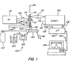
- FIG. 1 shows a schematic diagram of an Inductively Coupled Plasma-Optical Emission Spectroscopy (ICP-OES) system at 100.
- the ICP-OES 100 generally comprises a system for directing a carrier gas 102 to a torch 114 whereat the carrier gas 102 is ionized to form a hot plasma 116 (5,000 - 10.000K).
- the plasma 116 comprises a preheating zone 190, an induction zone 192, an initial radiation zone 194, an analytic zone 196 and a plasma tail 198.
- An atomized sample 104 is also directed to the plasma 116 through a pump 106, nebulizer 108 and spray chamber 162.
- a radio frequency (RF) power source 110 provides RF electrical power to the plasma 116 by way of a load coil 112.
- RF radio frequency
- the light 134 is collected by collection optics 118 and directed to a spectrometer 120 where it is spectrally resolved.
- a detector 122 detects the spectrally resolved light 134 and provides a signal 138, 140 to a microprocessor 122 and computer network 124 for analysis.
- FIG. 1 it is seen that the viewing of the plasma 116 is from a direction at a right angle to the plasma 116. However, it will be understood from FIG. 1 that the viewing of the plasma 116 may also be performed from a direction along the axis 126.
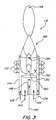
- the Inductively Coupled Plasma Spectroscopy performed herein may also be performed with a mass spectrometer (MS) 180 such as a quadrupole mass analyzer in an Inductively Coupled Plasma-Mass Spectroscopy (ICP-MS) system at 100 as seen in FIG. 2 .
- MS mass spectrometer
- ICP-MS Inductively Coupled Plasma-Mass Spectroscopy
- the RF power source 110 operates generally in the range of 10 to 100 MHz, particularly 20 - 50 MHz, e.g., 27 - 40 MHz.
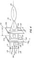
- FIG. 3 shows a more detailed rendition of the plasma 116 of FIGS. 1 and 2 .
- the torch 114 includes three concentric tubes.
- the innermost tube 148 provides atomized flow 146 of the sample into the plasma 116.
- the middle tube 150 provides auxiliary gas flow 144 to the plasma 116.
- the outermost tube of torch 114 provides carrier gas flow 128 for sustaining the plasma.
- the carrier gas flow 128 is directed to the plasma 116 in an laminar flow about the middle tube 150.
- the auxiliary gas flow 144 is directed to the plasma 116 within the middle tube 150 and the atomized sample flow 146 is directed to the plasma 116 from the spray chamber 162 along the innermost tube 148.
- the RF current in the load coil 112 forms a magnetic field within the load coil 112 so as to confine the plasma 116 therein.
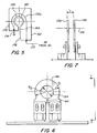
- FIGS. 4 - 11 show various configurations of an electrode 152, 156, 158.
- the electrode 152 comprises two parallel plates 152a, 152b positioned at a distance 'L' from one another.
- the parallel plates 152a, 152b each include an aperture 154 through which the torch 114 is positioned such that the torch 114 and the aperture 154 are aligned along an axis 126.
- the parallel plates 152a, 152b have a thickness of 't.'
- the aperture 154 of the electrode 152 also includes a slot 164, of width 'w' such that the aperture 154 is in communication with its surroundings.
- the electrode 152 is generally comprised of a square or rectangular planar shape, though it may be a wire as seen in FIG. 12 .
- the RF current supplied to the planar electrode comprises a planar current loop 172a generating a toroidal magnetic field 182 through the aperture 154 ( FIG. 12 ).
- the electrode 156 is of a rounded nature having an outside diameter of D 1 and inside aperture diameter of D 2 .
- the electrodes 152, 156 of FIGS. 4 - 7 are distinct elements which are supplied independently with RF electrical current 172 of opposite polarity.
- One part 176 of the electrode 152 is supplied with the RF power while a second part 178 of the electrode 152 is tied to a ground 174.
- the RF power and frequency supplied to each electrode 152 can be independently controlled and varied for optimum performance. For instance, each electrode 152 can be driven at a different frequency in order to optimize the plasma emission and excitation.
- one electrode can be operated in a continuous power mode while the other electrode can be modulated (e.g.; pulsed or gated).
- the distance, 'L', between the electrodes 152 can be adjusted since the electrodes 152 are not connected to one another; thus adjusting the power distribution within the plasma 116.
- the diameter, D 2 , of the aperture 154 can be independently adjusted in order to adjust the coupling characteristics between the RF power supply 110 and the plasma 116.
- the electrode 158 is shown as a single element having two electrodes 166, 168 connected to a common electrical ground 170.
- FIG. 14 a plurality of loop currents 184a, 184b is shown generated from a single RF electric current source 110.
- the loop currents 184a, 184b are oriented with respect to one another in such a manner that the alternating electric current in a first loop current 184 flows in a direction opposite to that of the alternating electric current in a second loop current 184b during alternating half cycles of a sinusoidally alternating current.
- a method and apparatus for spectroscopically analyzing a sample comprises generating a plasma; generating a magnetic field by a magnetic dipole wherein the plasma is confined within the magnetic field; introducing sample atoms into the plasma wherein excited sample atoms are confined; and analyzing the spectral or mass content of the exited sample atoms.
- a spectroscopic system comprises a magnetic dipole having an associated magnetic field; a plasma confined within the magnetic field; a sample of excited atoms introduced within the plasma; and a spectrometer for analyzing the spectral or mass content of the excited sample atoms.
Landscapes
- Physics & Mathematics (AREA)
- Engineering & Computer Science (AREA)
- Plasma & Fusion (AREA)
- Chemical & Material Sciences (AREA)
- Health & Medical Sciences (AREA)
- Analytical Chemistry (AREA)
- Biochemistry (AREA)
- Life Sciences & Earth Sciences (AREA)
- Nuclear Medicine, Radiotherapy & Molecular Imaging (AREA)
- General Health & Medical Sciences (AREA)
- General Physics & Mathematics (AREA)
- Immunology (AREA)
- Pathology (AREA)
- Electromagnetism (AREA)
- Spectroscopy & Molecular Physics (AREA)
- Investigating, Analyzing Materials By Fluorescence Or Luminescence (AREA)
- Other Investigation Or Analysis Of Materials By Electrical Means (AREA)
Claims (7)
- Spektroskopiesystem (100), Folgendes umfassend:einen Plasmabrenner (114);parallele Platten (152a, 152b), welche in einem Abstand voneinander positioniert sind, um Schleifenströme (184a, 184b) bereitzustellen, welche in Bezug aufeinander so ausgerichtet sind, dass ein elektrischer Wechselstrom (172a) in einem ersten Schleifenstrom (184a) in eine entgegengesetzte Richtung zu derjenigen eines Wechselstroms (172b) in einem zweiten Schleifenstrom (184b) während alternierender Halbzyklen eines sinusförmigen Wechselstroms strömt, um Magnetfelder (182a, 182b) zu erzeugen, welche eine gleiche räumliche Ausrichtung aufweisen, wobei jede der parallelen Platten (152a, 152b) eine Öffnung (154) einschließt, durch welche der Plasmabrenner (114) in solch einer Weise positioniert ist, dass der Plasmabrenner (114) und die Öffnung (154) entlang einer Achse (126) ausgefluchtet sind, um ein Magnetfeld (182a, 182b) und ein Plasma (116) innerhalb des Plasmabrenners (114) zu erzeugen, wobei das erzeugte Plasma (116) innerhalb der erzeugten Magnetfelder (182a, 182b) in dem Plasmabrenner (114) eingeschlossen ist;eine Pumpe (106), einen Vernebler (108) und eine Sprühkammer (162) zum Einleiten einer atomisierten Probe (104) in das erzeugte Plasma (116) in dem Plasmabrenner (114) zum Anregen von Probenatomen (104) zum Abgeben von Licht, während sie zu einem niedrigeren Zustand zerfallen;ein Spektrometer (120) zum Analysieren charakteristischer Merkmale der angeregten Atome (104) innerhalb des Plasmas (116) innerhalb des Plasmabrenners (114); undeine Radiofrequenz-Stromversorgung (110), welche elektrisch mit den parallelen Platten zum Erzeugen des ersten und des zweiten planaren Schleifenstroms (184a, 184b) gekoppelt ist.
- Spektroskopiesystem (100) nach Anspruch 1, wobei die parallelen Platten (152a, 152b) jeweils einen rechteckigen Querschnitt mit einem kreisförmigen inneren Querschnitt umfassen, welcher die Öffnungen (154) bildet.
- Verfahren zur spektroskopischen Analyse einer Materialprobe, wobei das Verfahren Folgendes umfasst:Bereitstellen eines Spektroskopiesystems (100) nach Anspruch 1 oder 2;Erzeugen eines Plasmas (116) unter Verwendung der parallelen Platten (152a, 152b), welche in einem Abstand voneinander positioniert sind, um Schleifenströme (184a, 184b) bereitzustellen, welche in Bezug aufeinander so ausgerichtet sind, dass ein elektrischer Wechselstrom (172a) in einem ersten Schleifenstrom (184a) in eine entgegengesetzte Richtung zu derjenigen eines Wechselstroms (172b) in einem zweiten Schleifenstrom (184b) während alternierender Halbzyklen eines sinusförmigen Wechselstroms strömt, um Magnetfelder (182a, 182b) zu erzeugen, welche eine gleiche räumliche Ausrichtung aufweisen, wobei das Plasma (116) innerhalb der erzeugten Magnetfelder (182a, 182b) in dem Plasmabrenner (114) eingeschlossen ist;Einleiten einer atomisierten Probe (104) in das erzeugte Plasma (116) in dem Plasmabrenner (114) durch die Pumpe (106), den Vernebler (108) und die Sprühkammer (162) zum Anregen von Probenatomen (104) zum Abgeben von Licht, während sie zu einem niedrigeren Zustand zerfallen; undAnalysieren charakteristischer Merkmale der angeregten Probenatome (104).
- Verfahren nach Anspruch 3, wobei Analysieren der charakteristischen Merkmale der angeregten Probenatome (104) Detektieren einer optischen Emission von angeregten Probenatomen (104) oder Bereitstellen der angeregten Atome an ein Massenspektrometer (180) umfasst.
- Verfahren nach Anspruch 3, ferner umfassend elektrisches Erden der Schleifenströme.
- Verfahren nach Anspruch 3, ferner umfassend Konfigurieren der parallelen Platten als ein einziges Element, welches zwei kreisförmige Elektroden (166, 168) mit einem kreisförmigen inneren Querschnitt aufweist, welcher die Öffnungen (154) bildet, wobei die Elektroden (166, 168) mit einer gemeinsamen elektrischen Erde (170) verbunden sind.
- Verfahren nach Anspruch 3, ferner umfassend Anpassen des Abstandes zwischen den parallelen Platten (152a, 152b).
Applications Claiming Priority (4)
| Application Number | Priority Date | Filing Date | Title |
|---|---|---|---|
| US43296302P | 2002-12-12 | 2002-12-12 | |
| US432963P | 2002-12-12 | ||
| US10/730,779 US7106438B2 (en) | 2002-12-12 | 2003-12-09 | ICP-OES and ICP-MS induction current |
| PCT/US2003/039440 WO2004055493A2 (en) | 2002-12-12 | 2003-12-11 | Icp-oes and icp-ms induction current |
Publications (3)
| Publication Number | Publication Date |
|---|---|
| EP1570254A2 EP1570254A2 (de) | 2005-09-07 |
| EP1570254A4 EP1570254A4 (de) | 2007-01-03 |
| EP1570254B1 true EP1570254B1 (de) | 2020-11-18 |
Family
ID=32912132
Family Applications (1)
| Application Number | Title | Priority Date | Filing Date |
|---|---|---|---|
| EP03790465.3A Expired - Lifetime EP1570254B1 (de) | 2002-12-12 | 2003-12-11 | Icp-oes- icp-ms-induktionsstrom |
Country Status (7)
| Country | Link |
|---|---|
| US (1) | US7106438B2 (de) |
| EP (1) | EP1570254B1 (de) |
| JP (1) | JP4290161B2 (de) |
| CN (1) | CN100529741C (de) |
| AU (1) | AU2003293514B2 (de) |
| CA (1) | CA2509525C (de) |
| WO (1) | WO2004055493A2 (de) |
Families Citing this family (19)
| Publication number | Priority date | Publication date | Assignee | Title |
|---|---|---|---|---|
| US7511246B2 (en) * | 2002-12-12 | 2009-03-31 | Perkinelmer Las Inc. | Induction device for generating a plasma |
| DE102004022200B4 (de) * | 2004-05-05 | 2006-07-20 | Actinium Pharmaceuticals, Inc. | Radium-Target sowie Verfahren zu seiner Herstellung |
| WO2006099190A2 (en) * | 2005-03-11 | 2006-09-21 | Perkinelmer, Inc. | Plasmas and methods of using them |
| US8622735B2 (en) * | 2005-06-17 | 2014-01-07 | Perkinelmer Health Sciences, Inc. | Boost devices and methods of using them |
| US7742167B2 (en) * | 2005-06-17 | 2010-06-22 | Perkinelmer Health Sciences, Inc. | Optical emission device with boost device |
| US20070046934A1 (en) * | 2005-08-26 | 2007-03-01 | New Wave Research, Inc. | Multi-function laser induced breakdown spectroscopy and laser ablation material analysis system and method |
| DE102006008023B4 (de) | 2006-02-21 | 2008-05-29 | Actinium Pharmaceuticals, Inc. | Verfahren zum Reinigen von 225Ac aus bestrahlten 226Ra-Targets |
| WO2008028664A1 (en) * | 2006-09-08 | 2008-03-13 | Actinium Pharmaceuticals, Inc. | Method for the purification of radium from different sources |
| US20110108058A1 (en) * | 2009-11-11 | 2011-05-12 | Axcelis Technologies, Inc. | Method and apparatus for cleaning residue from an ion source component |
| CN203556992U (zh) | 2010-05-05 | 2014-04-23 | 珀金埃尔默健康科学股份有限公司 | 感应装置、焰炬组件、光学发射装置、原子吸收装置以及质谱仪 |
| EP2566650B1 (de) | 2010-05-05 | 2019-10-02 | PerkinElmer Health Sciences, Inc. | Induktive vorrichtung und niedrigfluss-plasma damit |
| US8563924B2 (en) * | 2011-06-28 | 2013-10-22 | Agilent Technologies, Inc. | Windowless ionization device |
| US9259798B2 (en) | 2012-07-13 | 2016-02-16 | Perkinelmer Health Sciences, Inc. | Torches and methods of using them |
| CN207824151U (zh) * | 2014-01-28 | 2018-09-07 | 魄金莱默保健科学有限公司 | 感应装置及包括感应装置的系统 |
| US9165751B1 (en) | 2014-06-06 | 2015-10-20 | Agilent Technologies, Inc. | Sample atomization with reduced clogging for analytical instruments |
| US9673032B1 (en) | 2016-03-31 | 2017-06-06 | Agilent Technologies Inc. | Sample sprayer with adjustable conduit and related methods |
| US10195683B2 (en) * | 2016-11-14 | 2019-02-05 | Matthew Fagan | Metal analyzing plasma CNC cutting machine and associated methods |
| US10300551B2 (en) * | 2016-11-14 | 2019-05-28 | Matthew Fagan | Metal analyzing plasma CNC cutting machine and associated methods |
| US20240164005A1 (en) * | 2022-11-16 | 2024-05-16 | Perkinelmer U.S. Llc | Induction devices for inductively coupled plasma torches and methods and systems including same |
Family Cites Families (10)
| Publication number | Priority date | Publication date | Assignee | Title |
|---|---|---|---|---|
| US4540884A (en) | 1982-12-29 | 1985-09-10 | Finnigan Corporation | Method of mass analyzing a sample by use of a quadrupole ion trap |
| US4629940A (en) | 1984-03-02 | 1986-12-16 | The Perkin-Elmer Corporation | Plasma emission source |
| US4818916A (en) | 1987-03-06 | 1989-04-04 | The Perkin-Elmer Corporation | Power system for inductively coupled plasma torch |
| US4766287A (en) | 1987-03-06 | 1988-08-23 | The Perkin-Elmer Corporation | Inductively coupled plasma torch with adjustable sample injector |
| GB9203463D0 (en) | 1992-02-19 | 1992-04-08 | Applied Res Lab | Method and apparatus for analytical sample preparation |
| AU5017293A (en) * | 1992-09-01 | 1994-03-29 | University Of North Carolina At Chapel Hill, The | High pressure magnetically assisted inductively coupled plasma |
| US5526110A (en) | 1994-07-08 | 1996-06-11 | Iowa State University Research Foundation, Inc. | In situ calibration of inductively coupled plasma-atomic emission and mass spectroscopy |
| EP0792091B1 (de) | 1995-12-27 | 2002-03-13 | Nippon Telegraph And Telephone Corporation | Verfahren zur elementaren Analyse |
| JP2929275B2 (ja) * | 1996-10-16 | 1999-08-03 | 株式会社アドテック | 透磁コアを有する誘導結合型−平面状プラズマの発生装置 |
| US6329757B1 (en) | 1996-12-31 | 2001-12-11 | The Perkin-Elmer Corporation | High frequency transistor oscillator system |
-
2003
- 2003-12-09 US US10/730,779 patent/US7106438B2/en not_active Expired - Lifetime
- 2003-12-11 AU AU2003293514A patent/AU2003293514B2/en not_active Expired
- 2003-12-11 EP EP03790465.3A patent/EP1570254B1/de not_active Expired - Lifetime
- 2003-12-11 JP JP2005508319A patent/JP4290161B2/ja not_active Expired - Lifetime
- 2003-12-11 CA CA2509525A patent/CA2509525C/en not_active Expired - Lifetime
- 2003-12-11 CN CNB2003801095259A patent/CN100529741C/zh not_active Expired - Lifetime
- 2003-12-11 WO PCT/US2003/039440 patent/WO2004055493A2/en not_active Ceased
Non-Patent Citations (2)
| Title |
|---|
| HOPWOOD J ET AL: "Review of inductively coupled plasmas for plasma processing", PLASMA SOURCES SCIENCE AND TECHNOLOGY, INSTITUTE OF PHYSICS PUBLISHING, BRISTOL, GB, vol. 1, no. 2, 1 May 1992 (1992-05-01), pages 109 - 116, XP020070364, ISSN: 0963-0252, DOI: 10.1088/0963-0252/1/2/006 * |
| ROBERT H. SCOTT ET AL: "Inductively coupled plasma-optical emission analytical spectrometry", ANALYTICAL CHEMISTRY, vol. 46, no. 1, 1 January 1974 (1974-01-01), pages 75 - 80, XP055304840, ISSN: 0003-2700, DOI: 10.1021/ac60337a031 * |
Also Published As
| Publication number | Publication date |
|---|---|
| JP4290161B2 (ja) | 2009-07-01 |
| JP2006516325A (ja) | 2006-06-29 |
| WO2004055493A3 (en) | 2004-12-09 |
| CN1745295A (zh) | 2006-03-08 |
| US7106438B2 (en) | 2006-09-12 |
| WO2004055493A2 (en) | 2004-07-01 |
| AU2003293514A1 (en) | 2004-07-09 |
| CA2509525C (en) | 2011-03-22 |
| CN100529741C (zh) | 2009-08-19 |
| US20040169855A1 (en) | 2004-09-02 |
| EP1570254A2 (de) | 2005-09-07 |
| EP1570254A4 (de) | 2007-01-03 |
| CA2509525A1 (en) | 2004-07-01 |
| AU2003293514B2 (en) | 2007-07-19 |
| AU2003293514B8 (en) | 2004-07-09 |
Similar Documents
| Publication | Publication Date | Title |
|---|---|---|
| EP1570254B1 (de) | Icp-oes- icp-ms-induktionsstrom | |
| AU2006284864B2 (en) | Induction device for generating a plasma | |
| EP2566650B1 (de) | Induktive vorrichtung und niedrigfluss-plasma damit | |
| US10375811B2 (en) | Asymmetric induction devices and systems and methods using them |
Legal Events
| Date | Code | Title | Description |
|---|---|---|---|
| PUAI | Public reference made under article 153(3) epc to a published international application that has entered the european phase |
Free format text: ORIGINAL CODE: 0009012 |
|
| 17P | Request for examination filed |
Effective date: 20050617 |
|
| AK | Designated contracting states |
Kind code of ref document: A2 Designated state(s): AT BE BG CH CY CZ DE DK EE ES FI FR GB GR HU IE IT LI LU MC NL PT RO SE SI SK TR |
|
| AX | Request for extension of the european patent |
Extension state: AL LT LV MK |
|
| DAX | Request for extension of the european patent (deleted) | ||
| A4 | Supplementary search report drawn up and despatched |
Effective date: 20061204 |
|
| RIC1 | Information provided on ipc code assigned before grant |
Ipc: H01J 49/10 20060101ALI20061128BHEP Ipc: G01N 21/73 20060101AFI20041220BHEP |
|
| 17Q | First examination report despatched |
Effective date: 20070911 |
|
| STAA | Information on the status of an ep patent application or granted ep patent |
Free format text: STATUS: EXAMINATION IS IN PROGRESS |
|
| GRAP | Despatch of communication of intention to grant a patent |
Free format text: ORIGINAL CODE: EPIDOSNIGR1 |
|
| STAA | Information on the status of an ep patent application or granted ep patent |
Free format text: STATUS: GRANT OF PATENT IS INTENDED |
|
| INTG | Intention to grant announced |
Effective date: 20200529 |
|
| GRAS | Grant fee paid |
Free format text: ORIGINAL CODE: EPIDOSNIGR3 |
|
| GRAA | (expected) grant |
Free format text: ORIGINAL CODE: 0009210 |
|
| STAA | Information on the status of an ep patent application or granted ep patent |
Free format text: STATUS: THE PATENT HAS BEEN GRANTED |
|
| REG | Reference to a national code |
Ref country code: DE Ref legal event code: R081 Ref document number: 60352591 Country of ref document: DE Owner name: PERKINELMER HEALTH SCIENCES, INC. (N.D.GES.D. , US Free format text: FORMER OWNER: PERKINELMER LAS, INC., BOSTON, MASS., US |
|
| AK | Designated contracting states |
Kind code of ref document: B1 Designated state(s): AT BE BG CH CY CZ DE DK EE ES FI FR GB GR HU IE IT LI LU MC NL PT RO SE SI SK TR |
|
| REG | Reference to a national code |
Ref country code: GB Ref legal event code: FG4D |
|
| REG | Reference to a national code |
Ref country code: CH Ref legal event code: EP |
|
| REG | Reference to a national code |
Ref country code: DE Ref legal event code: R096 Ref document number: 60352591 Country of ref document: DE |
|
| REG | Reference to a national code |
Ref country code: IE Ref legal event code: FG4D |
|
| REG | Reference to a national code |
Ref country code: AT Ref legal event code: REF Ref document number: 1336292 Country of ref document: AT Kind code of ref document: T Effective date: 20201215 |
|
| REG | Reference to a national code |
Ref country code: AT Ref legal event code: MK05 Ref document number: 1336292 Country of ref document: AT Kind code of ref document: T Effective date: 20201118 |
|
| REG | Reference to a national code |
Ref country code: NL Ref legal event code: MP Effective date: 20201118 |
|
| PG25 | Lapsed in a contracting state [announced via postgrant information from national office to epo] |
Ref country code: PT Free format text: LAPSE BECAUSE OF FAILURE TO SUBMIT A TRANSLATION OF THE DESCRIPTION OR TO PAY THE FEE WITHIN THE PRESCRIBED TIME-LIMIT Effective date: 20210318 Ref country code: FI Free format text: LAPSE BECAUSE OF FAILURE TO SUBMIT A TRANSLATION OF THE DESCRIPTION OR TO PAY THE FEE WITHIN THE PRESCRIBED TIME-LIMIT Effective date: 20201118 Ref country code: GR Free format text: LAPSE BECAUSE OF FAILURE TO SUBMIT A TRANSLATION OF THE DESCRIPTION OR TO PAY THE FEE WITHIN THE PRESCRIBED TIME-LIMIT Effective date: 20210219 |
|
| PG25 | Lapsed in a contracting state [announced via postgrant information from national office to epo] |
Ref country code: SE Free format text: LAPSE BECAUSE OF FAILURE TO SUBMIT A TRANSLATION OF THE DESCRIPTION OR TO PAY THE FEE WITHIN THE PRESCRIBED TIME-LIMIT Effective date: 20201118 Ref country code: BG Free format text: LAPSE BECAUSE OF FAILURE TO SUBMIT A TRANSLATION OF THE DESCRIPTION OR TO PAY THE FEE WITHIN THE PRESCRIBED TIME-LIMIT Effective date: 20210218 Ref country code: AT Free format text: LAPSE BECAUSE OF FAILURE TO SUBMIT A TRANSLATION OF THE DESCRIPTION OR TO PAY THE FEE WITHIN THE PRESCRIBED TIME-LIMIT Effective date: 20201118 |
|
| PG25 | Lapsed in a contracting state [announced via postgrant information from national office to epo] |
Ref country code: SK Free format text: LAPSE BECAUSE OF FAILURE TO SUBMIT A TRANSLATION OF THE DESCRIPTION OR TO PAY THE FEE WITHIN THE PRESCRIBED TIME-LIMIT Effective date: 20201118 Ref country code: RO Free format text: LAPSE BECAUSE OF FAILURE TO SUBMIT A TRANSLATION OF THE DESCRIPTION OR TO PAY THE FEE WITHIN THE PRESCRIBED TIME-LIMIT Effective date: 20201118 Ref country code: EE Free format text: LAPSE BECAUSE OF FAILURE TO SUBMIT A TRANSLATION OF THE DESCRIPTION OR TO PAY THE FEE WITHIN THE PRESCRIBED TIME-LIMIT Effective date: 20201118 Ref country code: CZ Free format text: LAPSE BECAUSE OF FAILURE TO SUBMIT A TRANSLATION OF THE DESCRIPTION OR TO PAY THE FEE WITHIN THE PRESCRIBED TIME-LIMIT Effective date: 20201118 |
|
| REG | Reference to a national code |
Ref country code: CH Ref legal event code: PL |
|
| REG | Reference to a national code |
Ref country code: DE Ref legal event code: R097 Ref document number: 60352591 Country of ref document: DE |
|
| PG25 | Lapsed in a contracting state [announced via postgrant information from national office to epo] |
Ref country code: MC Free format text: LAPSE BECAUSE OF FAILURE TO SUBMIT A TRANSLATION OF THE DESCRIPTION OR TO PAY THE FEE WITHIN THE PRESCRIBED TIME-LIMIT Effective date: 20201118 Ref country code: DK Free format text: LAPSE BECAUSE OF FAILURE TO SUBMIT A TRANSLATION OF THE DESCRIPTION OR TO PAY THE FEE WITHIN THE PRESCRIBED TIME-LIMIT Effective date: 20201118 |
|
| REG | Reference to a national code |
Ref country code: BE Ref legal event code: MM Effective date: 20201231 |
|
| PLBE | No opposition filed within time limit |
Free format text: ORIGINAL CODE: 0009261 |
|
| STAA | Information on the status of an ep patent application or granted ep patent |
Free format text: STATUS: NO OPPOSITION FILED WITHIN TIME LIMIT |
|
| 26N | No opposition filed |
Effective date: 20210819 |
|
| PG25 | Lapsed in a contracting state [announced via postgrant information from national office to epo] |
Ref country code: LU Free format text: LAPSE BECAUSE OF NON-PAYMENT OF DUE FEES Effective date: 20201211 Ref country code: NL Free format text: LAPSE BECAUSE OF FAILURE TO SUBMIT A TRANSLATION OF THE DESCRIPTION OR TO PAY THE FEE WITHIN THE PRESCRIBED TIME-LIMIT Effective date: 20201118 Ref country code: FR Free format text: LAPSE BECAUSE OF NON-PAYMENT OF DUE FEES Effective date: 20210118 Ref country code: IE Free format text: LAPSE BECAUSE OF NON-PAYMENT OF DUE FEES Effective date: 20201211 Ref country code: IT Free format text: LAPSE BECAUSE OF FAILURE TO SUBMIT A TRANSLATION OF THE DESCRIPTION OR TO PAY THE FEE WITHIN THE PRESCRIBED TIME-LIMIT Effective date: 20201118 |
|
| PG25 | Lapsed in a contracting state [announced via postgrant information from national office to epo] |
Ref country code: SI Free format text: LAPSE BECAUSE OF FAILURE TO SUBMIT A TRANSLATION OF THE DESCRIPTION OR TO PAY THE FEE WITHIN THE PRESCRIBED TIME-LIMIT Effective date: 20201118 Ref country code: LI Free format text: LAPSE BECAUSE OF NON-PAYMENT OF DUE FEES Effective date: 20201231 Ref country code: CH Free format text: LAPSE BECAUSE OF NON-PAYMENT OF DUE FEES Effective date: 20201231 Ref country code: ES Free format text: LAPSE BECAUSE OF FAILURE TO SUBMIT A TRANSLATION OF THE DESCRIPTION OR TO PAY THE FEE WITHIN THE PRESCRIBED TIME-LIMIT Effective date: 20201118 |
|
| PG25 | Lapsed in a contracting state [announced via postgrant information from national office to epo] |
Ref country code: TR Free format text: LAPSE BECAUSE OF FAILURE TO SUBMIT A TRANSLATION OF THE DESCRIPTION OR TO PAY THE FEE WITHIN THE PRESCRIBED TIME-LIMIT Effective date: 20201118 Ref country code: CY Free format text: LAPSE BECAUSE OF FAILURE TO SUBMIT A TRANSLATION OF THE DESCRIPTION OR TO PAY THE FEE WITHIN THE PRESCRIBED TIME-LIMIT Effective date: 20201118 |
|
| PG25 | Lapsed in a contracting state [announced via postgrant information from national office to epo] |
Ref country code: BE Free format text: LAPSE BECAUSE OF NON-PAYMENT OF DUE FEES Effective date: 20201231 |
|
| REG | Reference to a national code |
Ref country code: DE Ref legal event code: R081 Ref document number: 60352591 Country of ref document: DE Owner name: PERKINELMER HEALTH SCIENCES, INC. (N.D.GES.D. , US Free format text: FORMER OWNER: PERKINELMER LAS, INC., BOSTON, MASS., US |
|
| PGFP | Annual fee paid to national office [announced via postgrant information from national office to epo] |
Ref country code: GB Payment date: 20221020 Year of fee payment: 20 Ref country code: DE Payment date: 20221018 Year of fee payment: 20 |
|
| P01 | Opt-out of the competence of the unified patent court (upc) registered |
Effective date: 20230601 |
|
| REG | Reference to a national code |
Ref country code: DE Ref legal event code: R071 Ref document number: 60352591 Country of ref document: DE |
|
| REG | Reference to a national code |
Ref country code: GB Ref legal event code: PE20 Expiry date: 20231210 |
|
| PG25 | Lapsed in a contracting state [announced via postgrant information from national office to epo] |
Ref country code: GB Free format text: LAPSE BECAUSE OF EXPIRATION OF PROTECTION Effective date: 20231210 |
|
| PG25 | Lapsed in a contracting state [announced via postgrant information from national office to epo] |
Ref country code: GB Free format text: LAPSE BECAUSE OF EXPIRATION OF PROTECTION Effective date: 20231210 |