EP1570209B1 - Drehbarer ölbrenner - Google Patents
Drehbarer ölbrenner Download PDFInfo
- Publication number
- EP1570209B1 EP1570209B1 EP03776852A EP03776852A EP1570209B1 EP 1570209 B1 EP1570209 B1 EP 1570209B1 EP 03776852 A EP03776852 A EP 03776852A EP 03776852 A EP03776852 A EP 03776852A EP 1570209 B1 EP1570209 B1 EP 1570209B1
- Authority
- EP
- European Patent Office
- Prior art keywords
- cup
- oil
- partition
- burner
- atomizer
- Prior art date
- Legal status (The legal status is an assumption and is not a legal conclusion. Google has not performed a legal analysis and makes no representation as to the accuracy of the status listed.)
- Expired - Lifetime
Links
- 238000005192 partition Methods 0.000 claims abstract description 37
- 238000002485 combustion reaction Methods 0.000 claims abstract description 36
- 230000002093 peripheral effect Effects 0.000 claims description 24
- 239000002245 particle Substances 0.000 claims description 15
- 239000003595 mist Substances 0.000 claims description 7
- 239000003921 oil Substances 0.000 abstract description 82
- 235000019198 oils Nutrition 0.000 abstract description 82
- 238000001816 cooling Methods 0.000 abstract description 11
- 235000015112 vegetable and seed oil Nutrition 0.000 abstract description 5
- 239000008158 vegetable oil Substances 0.000 abstract description 5
- 239000000295 fuel oil Substances 0.000 abstract description 4
- 238000005086 pumping Methods 0.000 abstract description 4
- 230000008642 heat stress Effects 0.000 abstract description 3
- 238000010276 construction Methods 0.000 abstract description 2
- CURLTUGMZLYLDI-UHFFFAOYSA-N Carbon dioxide Chemical compound O=C=O CURLTUGMZLYLDI-UHFFFAOYSA-N 0.000 description 6
- 238000000034 method Methods 0.000 description 5
- 238000010438 heat treatment Methods 0.000 description 4
- XAGFODPZIPBFFR-UHFFFAOYSA-N aluminium Chemical compound [Al] XAGFODPZIPBFFR-UHFFFAOYSA-N 0.000 description 3
- 229910052782 aluminium Inorganic materials 0.000 description 3
- 239000004411 aluminium Substances 0.000 description 3
- 229910002092 carbon dioxide Inorganic materials 0.000 description 3
- 239000001569 carbon dioxide Substances 0.000 description 3
- 239000000446 fuel Substances 0.000 description 3
- 239000007788 liquid Substances 0.000 description 3
- UGFAIRIUMAVXCW-UHFFFAOYSA-N Carbon monoxide Chemical class [O+]#[C-] UGFAIRIUMAVXCW-UHFFFAOYSA-N 0.000 description 2
- 238000000889 atomisation Methods 0.000 description 2
- 229910002091 carbon monoxide Inorganic materials 0.000 description 2
- 238000004519 manufacturing process Methods 0.000 description 2
- 239000010499 rapseed oil Substances 0.000 description 2
- OKTJSMMVPCPJKN-UHFFFAOYSA-N Carbon Chemical compound [C] OKTJSMMVPCPJKN-UHFFFAOYSA-N 0.000 description 1
- NINIDFKCEFEMDL-UHFFFAOYSA-N Sulfur Chemical compound [S] NINIDFKCEFEMDL-UHFFFAOYSA-N 0.000 description 1
- 239000005864 Sulphur Substances 0.000 description 1
- 230000015572 biosynthetic process Effects 0.000 description 1
- 229910052799 carbon Inorganic materials 0.000 description 1
- 239000000571 coke Substances 0.000 description 1
- 239000004020 conductor Substances 0.000 description 1
- 230000000694 effects Effects 0.000 description 1
- 238000000605 extraction Methods 0.000 description 1
- 238000010304 firing Methods 0.000 description 1
- 239000000463 material Substances 0.000 description 1
- VNWKTOKETHGBQD-UHFFFAOYSA-N methane Chemical class C VNWKTOKETHGBQD-UHFFFAOYSA-N 0.000 description 1
- 239000000203 mixture Substances 0.000 description 1
- 238000012544 monitoring process Methods 0.000 description 1
- 230000007935 neutral effect Effects 0.000 description 1
- 230000005855 radiation Effects 0.000 description 1
- 239000013049 sediment Substances 0.000 description 1
- XLYOFNOQVPJJNP-UHFFFAOYSA-N water Substances O XLYOFNOQVPJJNP-UHFFFAOYSA-N 0.000 description 1
Images

Classifications
-
- F—MECHANICAL ENGINEERING; LIGHTING; HEATING; WEAPONS; BLASTING
- F23—COMBUSTION APPARATUS; COMBUSTION PROCESSES
- F23D—BURNERS
- F23D11/00—Burners using a direct spraying action of liquid droplets or vaporised liquid into the combustion space
- F23D11/04—Burners using a direct spraying action of liquid droplets or vaporised liquid into the combustion space the spraying action being obtained by centrifugal action
- F23D11/06—Burners using a direct spraying action of liquid droplets or vaporised liquid into the combustion space the spraying action being obtained by centrifugal action using a horizontal shaft
-
- F—MECHANICAL ENGINEERING; LIGHTING; HEATING; WEAPONS; BLASTING
- F23—COMBUSTION APPARATUS; COMBUSTION PROCESSES
- F23C—METHODS OR APPARATUS FOR COMBUSTION USING FLUID FUEL OR SOLID FUEL SUSPENDED IN A CARRIER GAS OR AIR
- F23C2900/00—Special features of, or arrangements for combustion apparatus using fluid fuels or solid fuels suspended in air; Combustion processes therefor
- F23C2900/99009—Combustion process using vegetable derived fuels, e.g. from rapes
Definitions
- the invention relates to a burner to combust oil in a combustion chamber.
- the burner is of the kind that comprises a burner casing; an atomizer cup mounted in the burner casing and arranged to supply oil to be burned to the combustion chamber and designed with a base and a tubular wall having a peripheral edge; an oil pump for metering the oil during operation to the interior of the atomizer cup; a shaft rotatably journaled in the burner casing and firmly connected to the base of the atomizer cup; a motor for rotating the shaft during operation at such high rates that the centrifugal force will make the oil in the atomizer cup leave its peripheral edge in a mist of fine oil particles; and a blower for supplying air to the combustion chamber for burning of the oil particles.
- Oil is largely used as fuel in e.g. boilers for production of heat energy.
- the oil does not burn readily in the combustion chamber of such a boiler as long as it is in its original liquid state. Normally the oil is therefore atomized to fine oil particles that burn far better and purer in the combustion chamber.
- a widely used atomization technique consists in the oil being forced into the combustion chamber at a relatively high pressure via a nozzle and is atomized on discharge from the nozzle outlet where the pressure drops suddenly. To avoid the nozzle clogging more or less, a not too heavy a fuel must be used in this case which also is of a high and uniform quality. These demands will normally be met by oil which is used for heating private residences where the boilers are relatively small.
- This technique is especially suited for small boilers as the flame easily can be modulated to a small size fitting the relatively small combustion chambers of the boilers at the same time as the flame is kept at such a great distance from the nozzle that this nozzle is not damaged by the heat from the flame.
- Heavy oils of varying grade are normally less expensive than the above oils and are therefore readily used if possible. These oils can especially be used as fuel in relatively large boilers where they are atomized by means of rotary burners with rapidly rotating atomizer cups which are not likely to clog as nozzles are.
- Rotary burners of this type are well suited for, as mentioned above, relatively large boilers with correspondingly large combustion chambers that allow the flame to spread freely.
- a burner of the kind mentioned in the opening paragraph is provided, which is arranged to be used in relatively small boilers.
- a burner of the kind mentioned in the opening paragraph is provided, which is provided with an atomizer cup which, during operation, is rotating at greater speeds than hitherto known.
- a burner of the kind mentioned in the opening paragraph is provided, which is arranged in such a way that the atomizer cup is not damaged by the heat stress from the flame.
- a burner of the kind mentioned in the opening paragraph is provided, which is arranged to burn heavy oils of varying grade, for example vegetable oils.
- a burner of the kind mentioned in the opening paragraph is provided, which is provided with an automatic suction atomizer cup.
- a burner of the kind mentioned in the opening paragraph is provided, which has a simple and reliable construction.
- the burner comprises an inlet cup facing in opposite direction from the atomizer cup and designed with a tubular wall with a peripheral edge and a base joint with the base of the atomizer cup; at least one guide channel extending obliquely through this base at a shorter distance from the rotational axis on the side of the inlet cup than on the side of the atomizer cup; and at least one oil duct connected to the at least one oil pump and opening into an area between the shaft and the inside of the wall of the inlet cup.
- Such a burner can function with a relatively small cup and correspondingly very high rotational speed in a relatively small combustion chamber of the type found in boilers for heating of e.g. private residences.
- the oil is supplied to the inlet cup in an area outside the shaft and led from there to the atomizer cup via the guide channels, after which it is thrown in finely atomized state out of the peripheral edge of the atomizer cup under the influence of the centrifugal force.
- the burner casing can be designed with an air chamber receiving combustion air from the blower of the burner and defined in the burner casing by a first partition at the atomizer cup and a second one at the atomizer cup.
- a slit for primary air can furthermore be made in the second partition at the peripheral edge of the atomizer cup and a number of apertures or a slit for secondary air can be made near the periphery of the burner casing.
- this base functions as a centrifugal pump which furthermore affects the oil with a significant force in the direction of the channels.
- the combination of this force and the centrifugal force causes the oil to settle on the inside of the atomizer cup in an extremely thin oil film.
- the inside face of the atomizer cup is cone-shaped. Therefore the centrifugal force has a component directed towards the peripheral edge of the atomizer cup. Under the influence of this component of force the oil film travels on the interior wall of the atomizer cup continuously towards its peripheral edge where the extremely thin oil film now is successively broken into extremely fine oil particles that are spread in the combustion chamber as a mist.
- the extremely fine oil particles burn far quicker than conventionally, resulting in a relatively small flame being able to develop just as much heat as a larger one but burning slower than a conventional flame.
- the burner according to the invention is therefore suitable for use in relatively small boilers with relatively small combustion chambers.
- the inlet cup communicates with the air chamber via a relatively narrow slit between the first partition and the peripheral edge of the atomizer cup.
- the base between the inlet cup and the atomizer cup functions as a centrifugal pump pumping oil from the inlet cup to the atomizer cup.
- the centrifugal pump is however pumping air from the inlet cup to the atomizer cup whereby a negative pressure is created in the inlet cup that drives an airflow through the narrow slit.
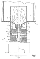
- the oil burner shown comprises a burner 1 with a motor 2.
- the burner supplies a combustion chamber 3 in a boiler 4 with finely atomized oil which is spread in a mist of extremely fine oil particles burning in a flame 5.
- a shaft 8 is rotatably journaled in a burner casing 6 by means of ball bearings 7, the shaft being rotated by the motor 2 during operation at very high shaft speed, for example 25,000 n/min.
- a blade wheel 9 is furthermore mounted that together with a blower chamber 10 made in the burner casing between a back wall 11 and a partition 12 form a blower.
- the blower draws air into the blower chamber via a number of intake apertures 13 made in the wall of the burner casing and blows the drawn-in air out via a number of blow-off apertures 14 made in the partition 12.
- the partition 12 Together with a second partition 15 the partition 12 defines an air chamber 16 which is provided with air from the pump chamber via the blow-off apertures 14.
- the second partition 15 increases outwards in the firing direction in a configuration that mainly follows the back of the flame 5 at an appropriate distance. Therefore there is no unfavourable space between the second partition and the flame, in which turbulent flows could be generated that would disturb the flame so that this flame would not be able to burn properly and purely.
- a base 18 On a cone 17 at the end of the shaft 8 a base 18 is firmly mounted with an atomizer cup 19 facing its opening in towards the combustion chamber 3 and an inlet cup 20 facing its opening in towards the partition 12 in the burner casing 6.
- a slit 21 is made near the atomizer cup and a number of apertures or a slit 22 is made near the periphery of the burner casing.
- the second partition 15 is extending inwards towards the first partition 12 in a funnel 23 surrounding the outer face 24 of the inlet and atomizer cup 20, 19 and together with this outer face defining an annular air nozzle 25 opening into the slit 21.
- the atomizer cup 19 has a first tubular wall 26 with a first conical inside face 27 and a first peripheral edge 28.
- the inlet cup 20 has a second tubular wall 29 with a second conical inside face 30 and a second peripheral edge 31. Both inside faces 27 and 30 are located on a conical surface with peak in the rotational axis 32 and in the case shown, on the.same conical surface.
- the flame formation is controlled the best at the same time as the formed oil particles obtain the desired extremely small size if the conical surface forms an angle with the rotational axis 32 of between 6° and 10°, especially between 7° and 9° in combination with the peripheral edge of the atomizer cup 19 having a diameter of between 20 mm and 100 mm, preferably between 20 mm and 50 mm, and especially 30 mm, and the rotational speed being between 10,000 n/min. and 40,000 n/min., preferably between 20,000 n/min. and 30,000 n/min., and especially 25,000 n/min.
- the joint base 18 of the cups is furthermore designed with a number of guide channels 33 that open at a shorter distance from the rotational axis 32 on side of the inlet cup than on the side of the atomizer cup.
- the first partition 12 is designed with a projection 34 extending into the inlet cup 20 at a short distance from the base 18 and near the peripheral edge 31 of the inlet cup which furthermore is near the partition 12. As it appears, a narrow slit 35 is thereby formed between the inlet cup 20 on the one hand and the partition 12 with its projection 34 on the other hand.
- a pump serves for pumping the oil to be burned into the inlet cup 20 via an oil duct 36 made in the first partition 12 and in through the projection 34 of this partition to near the base 18 of the cup and at least essentially within the circle of outlets of the guide channels 33 in the inlet cup.
- the burner is furthermore provided with an air distributor shell 37 extending in continuation of the burner casing 6 a distance into the combustion chamber 3 and also with an igniter 38 located near the distributor shell and connected to an ignition unit (not shown) via an electric line 39.
- the burner is furthermore provided with a control box, not shown, with among other things monitoring automatics and flame monitor.
- the inlet cup 20 receives oil from the oil pump via the oil duct 36 in the first partition 12.
- the inclined guide channels 33 function as the blades in a centrifugal pump which effectively pumps air from the air chamber 16 to the atomizer cup 19 via the narrow slit 35 between the inlet cup 20 and the partition 12 with its projection 34.
- the pump can therefore, at least essentially, be unpressurized and mainly only function as metering pump to meter the amount of oil that is continuously used for producing the desired heating effect.
- the outlet of the oil duct 36 is near the base 18 of the inlet cup 20 and at least partly within the outlet of the guide channels 33 in the inlet cup.
- the oil therefore settles in a thin oil layer on the base. Under the influence of the centrifugal force this oil layer travels continuously outwards in direction towards the conic inside face 30 of the tubular wall 29 of the inlet cup 20.
- the oil layer undergoes a severe splitting resulting in at least a part of the oil layer being transformed into oil particles that are mixed with the cooling airflow.
- the centrifugal force makes the rest of the oil layer flow through the guide channels in liquid state along the area that is farthest from the rotational axis 32.
- the oil film continuously travels towards the peripheral edge 28 of the atomizer cup where it is split up into extremely small oil particles that leave the edge as a flat mist.
- the blower draws fresh air into the blower chamber 10 via the intake apertures 13 and blows the drawn-in air into the air chamber 16 via the blow-off apertures 14.
- the air is now divided into three airflows, namely a primary airflow, a secondary airflow, and a cooling airflow that all finally will form part of the combustion air for the combustion process.
- the primary air constituting a smaller part of the total amount of air is blown at appropriate rate out through the air nozzle 25.
- This primary airflow serves to, via the air distributor shell, draw the flat oil mist leaving the peripheral edge of the atomizer cup out into the combustion chamber of the boiler so that it will not burn so close to the atomizer cup that this cup is damaged by the heat from the flame. It has proven that the peripheral edge of the atomizer cup and the flame can be spaced between 10 mm and 40 mm.
- the secondary air is blown out through the apertures or slit 22 of the second partition 15 near the air distributor shell 37 where it modulates the flame and keeps it free of the inside face of the shell.
- the secondary air contributes with the chief part of the required combustion air.
- the atomizer cup is located at a position in which it inevitably will receive a significant amount of radiation heat from the flame and its surroundings. It is important that the cup is not damaged during this so that it is thrown off balance and shakes the burner to pieces during its rapid rotation.
- the cooling air flowing out through the aperture of the atomizer cup acts to some extent as a shield shielding the cup against the heat stress, the cooling air absorbing heat concurrently with it getting nearer the flame.
- This air is in itself cooled when it is drawn via the narrow slit 35 between the inlet cup 20 and the partition 12 with its projection 34 into the atomizer cup 19 from the air chamber 16 of the joint base 18 of the cups, the base functioning, due to the presence of the guide channels 33, as a centrifugal pump which is very effective because the cooling air passing the guide channels is mixed with oil particles that are much heavier than the air.
- the sharp pressure drop produced over the narrow slit 35 causes the air to expand and thereby its temperature to drop drastically.
- the now cold air or the cooling air subsequently flows through the inlet cup, the guide channels, and the atomizer cup. Thereby the entire cup is cooled so effectively that it can be made of a material such as e.g. aluminium which in conventional burners would be destroyed by the great heat impact from the burning flame.
- the burner according to the invention is well suited for heavy oils of varying grade such as e.g. vegetable oils. Thereby a perspective of global significance is opened.
- a boiler is burned with 2 kg rape oil per hour by means of a rotary oil burner according to the invention.
- the rape oil is of the following quality: Ash 0.068 w% Coke remainder 0.51 w% Density at 15°C 0.9209 g/ml Flash point. >140 °C Upper calorific value 44.35 MJ/kg Lower calorific value 41.78 MJ/kg Pour point -24 °C Sediments at extraction 0.02 w% Sulphur ⁇ 0.05 w% Viscosity at 40°C 34.7 cSt Water 1480 ppm by weight
- the atomizer cup of the burner had a diameter at the peripheral edge of 30 mm and a depth, of 10 mm whereas its inlet cup had a diameter at the peripheral edge of 20 mm and a depth of 10 mm.
- the joint base of the two cups had a thickness of 10 mm and their conicity was 8° measured as the angle between a generator and the rotational axis.
- the entire cup was made of aluminium and was mounted on a shaft which was rotated at a rotational speed of 25,000 rpm by means of a direct-driven motor of 0.25 kW.
- the air was drawn in from an air chamber with an air temperature of 40 °C via a narrow slit with a width of 0.1 mm and length of about 11 mm whereby the air temperature dropped to minus 12 °C.
- the cold air kept the atomizer cup temperature at about 115 °C. After 100 operating hours there were no signs of the atomizer cup being damaged by the heat from the flame.
- the content of carbon monoxide was 15 ppm and total unburnt was 22 ppm.
Landscapes
- Engineering & Computer Science (AREA)
- Chemical & Material Sciences (AREA)
- Combustion & Propulsion (AREA)
- Mechanical Engineering (AREA)
- General Engineering & Computer Science (AREA)
- Nozzles (AREA)
- Combustion Of Fluid Fuel (AREA)
- Feeding And Controlling Fuel (AREA)
Claims (10)
- Ein Brenner zum Verbrennen von Öl in einer Brennkammer (3), mit- einem Brennergehäuse (6),- einem Atomisierungsbecher (19), der in dem Brennergehäuse (6) montiert ist und zum Liefern von zu verbrennendes Öl in die Verbrennungskammer angeordnet und mit einer Kammer (18) mit einer ersten ringförmigen Wand (26) mit einer ersten Umfangskante (28) versehen ist,- wenigstens einer Ölpumpe zum dosierten Einbringen des Öls in das Innere des Atomisierungsbechers (19) während des Betriebs,- einer Welle (8) die drehbar in dem Brennergehäuse (6) gelagert ist und an einem Ende fest mit der Basis (18) des Atomisierungsbecher (19) verbunden ist,- einem Motor (2) zum Drehen der Welle (8) während des Betriebs mit einer derart hohen Rate, dass die Zentrifugalkraft das Öl in dem Atomisierungsbecher (19) den Umfangsrand dieses Bechers in einem Nebel von feinen Ölpartikeln verlässt,- wenigstens einem Gebläse (9, 10) zum Zuführen von Luft in die Kammer (3) zum Verbrennen der feinen Ölpartikel,- einem Einlassbecher (20), der in die entgegengesetzte Richtung zu dem Atomisierungsbecher (19) weist und mit einer zweiten ringförmigen Wandung mit einem zweiten Umfangsrand (31) und mit der Basis (18), die mit der Basis (18) des Atomisierungsbechers (19) verbunden ist, ausgebildet ist,- wenigstens einer Ölleitung (36) die mit der wenigstens einen Ölpumpe verbunden ist und sich in einen Bereich zwischen der Welle (8) und der Innenfläche (30) der Wand (29) des Einlassbechers (30) öffnet,dadurch gekennzeichnet, dass der Brenner weiter aufweist:- wenigstens einen Führungskanal (33) für die Verbrennungsluft und das Öl, der sich schräg durch die Basis (18) mit einem kürzeren Abstand von der Rotationsachse (32) auf der Seite des Einlassbechers (20) als auf der Seite des Atomisierungsbechers (19) erstreckt, wobei eine erste Trennwand (12) sich mit einem Vorsprung (34) in das Innere des Einlassbechers (20) derart erstreckt, dass ein Schlitz (35) nahe genug zum Erzeugen eines plötzlichen Druckabfalls in der Verbrennungsluft, die den Schlitz passiert, der zwischen dem Einlassbecher (20) und der Trennwandung (12) und dessen Vorsprung (34) gebildet wird.
- Ein Brenner nach Anspruch 1, dadurch gekennzeichnet, dass die erste- und zweite Innenfläche (27; 30) der ringförmigen Wandung (26) des Atomisierungsbechers (19) und die ringförmige Wand (29) des Einlassbechers (20) auf jeder ihrer Rotationsflächen mit einem zunehmenden Durchmesser in der Richtung von dem Einlassbecher (20) zu dem Atomisierungsbecher (19) angeordnet sind.
- Ein Brenner nach Anspruch 1 oder 2, dadurch gekennzeichnet, dass die erste und die zweite Innenfläche (27; 30) der ringförmigen Wand (26; 29) des Atomisierungsbechers (19) bzw. des Einlassbechers (20) an einer konischen Fläche mit der Spitze in der Drehachse (32) angeordnet sind.
- Ein Brenner nach Anspruch 1, 2 oder 3, dadurch gekennzeichnet, dass die Innenfläche des wenigstens einen Führungskanals (33) durch die Basis (18), die den Einlassbecher (20) von dem Atomisierungsbecher (19) trennt, mit einer Erzeugenden der konischen Fläche entlang einer Linie oder einem Fläche fluchtet.
- Ein Brenner nach einem der Ansprüche 1 - 4, dadurch gekennzeichnet, dass- die Luftkammer (16) zum Aufnehmen der Verbrennungsluft von dem wenigstens einen Gebläse (9, 10) in einer Fläche um den Einlassbecher (20) und dem Atomisierungsbecher (19) in dem Brennergehäuse ausgebildet ist,- die Luftkammer (16) durch eine erste Trennwand (12) in dem Einlassbecher (20) und eine zweite Trennwand (15) an dem Atomisierungsbecher (19) begrenzt wird, und- ein Schlitz (21) in der zweiten Trennwand (15) nahe dem Atomisierungsbecher (19) vorgesehen ist und eine Anzahl von Öffnungen oder ein Schlitz (20) nahe der Peripherie des Brennergehäuses (6) vorgesehen ist.
- Ein Brenner nach Anspruch 5, dadurch gekennzeichnet, dass- der Einlassbescher (29) und der Atomisierungsbecher (19) eine gemeinsame Außenfläche haben,- ein Kanal (23) mit einem Abstand um diese Außenfläche angeordnet ist, der sich von einem Bereich nahe der ersten Trennwand (12) zu einem Bereich nahe dem Schlitz (21) der zweiten Trennwand erstreckt, und- die Außenfläche (24) gemeinsam mit der Innenfläche des Kanals (23) eine ringförmige Düse (25) bildet.
- Ein Brenner nach Anspruch 6, dadurch gekennzeichnet, dass- die erste Trennwand (12) mit einem relativ geringen axialen Abstand von dem Umfangsrand des Einlassbechers (20) angeordnet ist,- der Vorsprung (34) ringförmig ausgebildet ist, wobei der Vorsprung die Welle (8) umgibt und sich in den Einlassbecher (20) mit einem relativ kurzen radialen Abstand von dem Umfangsrand (31) dieses Bechers und gleichzeitig mit einem relativ kurzen axialen Abstand von seiner Basis gegeben ist, erstreckt, und- die wenigstens eine Ölleitung (36) in der ersten Trennwand (12) vorgesehen ist und sich in den Vorsprung (34) dieser Trennwand öffnet.
- Ein Brenner nach Anspruch 6 oder 7, dadurch gekennzeichnet, dass- der Ventilator (9) des Gebläses auf der Welle (8) montiert ist,
die Welle (8) einerseits in der ersten Trennwand und andererseits n einer Rückwand (11) in dem Brennergehäuse (6) gelagert ist,- eine Gebläsekammer (10) für den Ventilator (9) zwischen der Rückwand (11) und der ersten Trennwand (12) vorgesehen ist und- die Druckseite der Gebläsekammer (10) mit der Luftkammer (16) über Ausblasöffnungen (14) in der ersten Trennwand (12) verbunden ist und die Saugseite mit der Umgebung über Einlassöffnungen (12) in dem Brennergehäuse (6) verbunden ist. - Ein Brenner nach einem der Ansprüche 1 - 8, dadurch gekennzeichnet, dass eine Erzeugende der konischen Fläche einen Winkel mit der Drehachse von zwischen 6° und 10°, insbesondere zwischen 7° und 9°, bildet.
- Ein Brenner nach einem der Ansprüche 1 - 9, dadurch gekennzeichnet, dass der Atomisierungsbecher an seiner Umfangsfläche einen Durchmesser von zwischen 20mm und 100mm vorzugsweise zwischen 20mm und 50mm und insbesondere 30mm hat, und dass die Rotationsgeschwindigkeit zwischen 10.000 n/min und 40,000 n/mm, vorzugsweise zwischen 20,000 n/min und 30,000 n/min und besonders bevorzugt zwischen 25.000 n/min beträgt.
Applications Claiming Priority (3)
| Application Number | Priority Date | Filing Date | Title |
|---|---|---|---|
| DK200201879 | 2002-12-06 | ||
| DKPA200201879 | 2002-12-06 | ||
| PCT/DK2003/000837 WO2004053393A1 (en) | 2002-12-06 | 2003-12-05 | A rotary oil burner |
Publications (2)
| Publication Number | Publication Date |
|---|---|
| EP1570209A1 EP1570209A1 (de) | 2005-09-07 |
| EP1570209B1 true EP1570209B1 (de) | 2011-08-24 |
Family
ID=32479655
Family Applications (1)
| Application Number | Title | Priority Date | Filing Date |
|---|---|---|---|
| EP03776852A Expired - Lifetime EP1570209B1 (de) | 2002-12-06 | 2003-12-05 | Drehbarer ölbrenner |
Country Status (4)
| Country | Link |
|---|---|
| EP (1) | EP1570209B1 (de) |
| AT (1) | ATE521853T1 (de) |
| AU (1) | AU2003289702A1 (de) |
| WO (1) | WO2004053393A1 (de) |
Families Citing this family (2)
| Publication number | Priority date | Publication date | Assignee | Title |
|---|---|---|---|---|
| US20150000648A1 (en) * | 2013-06-28 | 2015-01-01 | Chinhu Jung | Portable stove |
| CN116066270B (zh) * | 2023-03-08 | 2023-06-09 | 山东赛马力发电设备有限公司 | 一种燃烧发动机可燃混合物的混合设备 |
Family Cites Families (5)
| Publication number | Priority date | Publication date | Assignee | Title |
|---|---|---|---|---|
| GB147827A (en) * | 1914-11-30 | 1921-09-01 | William Ruth Ray | Improvements in and relating to oil-burning apparatus |
| US1490861A (en) | 1922-04-26 | 1924-04-15 | Hydro Carbon Burner Mfg Compan | Hydrocarbon-oil burner |
| US1861216A (en) * | 1927-08-11 | 1932-05-31 | A T Oil Burner Co | Oil burner |
| GB620596A (en) | 1945-08-01 | 1949-03-28 | Jakob Meier | Improvements in and relating to liquid fuel burners |
| ES8103823A1 (es) * | 1979-10-01 | 1981-03-16 | Tome Fernandez Montserrat | Quemador rotativo de aceites pesados |
-
2003
- 2003-12-05 AT AT03776852T patent/ATE521853T1/de not_active IP Right Cessation
- 2003-12-05 AU AU2003289702A patent/AU2003289702A1/en not_active Abandoned
- 2003-12-05 EP EP03776852A patent/EP1570209B1/de not_active Expired - Lifetime
- 2003-12-05 WO PCT/DK2003/000837 patent/WO2004053393A1/en not_active Ceased
Also Published As
| Publication number | Publication date |
|---|---|
| WO2004053393A1 (en) | 2004-06-24 |
| ATE521853T1 (de) | 2011-09-15 |
| AU2003289702A1 (en) | 2004-06-30 |
| EP1570209A1 (de) | 2005-09-07 |
Similar Documents
| Publication | Publication Date | Title |
|---|---|---|
| US4830605A (en) | Combustion apparatus and method of forcibly circulating a heating medium in a combustion apparatus | |
| US1733792A (en) | Combustion apparatus | |
| US9874349B2 (en) | Fuel combustion system | |
| EP1570209B1 (de) | Drehbarer ölbrenner | |
| JPS6243091B2 (de) | ||
| US20250390072A1 (en) | Precise concentration generating device for dust particles and dust generation simulation method thereof | |
| US20100209858A1 (en) | Combustion system for atomizing fuel mixture in burner box | |
| US9657938B2 (en) | Fuel combustion system | |
| CA1203435A (en) | Solid fuel pulverizing and burning system and method and pulverizer and burner therefor | |
| US2620864A (en) | Rotary oil burner | |
| US1101779A (en) | Centrifugal burner. | |
| US2765842A (en) | Hydrocarbon burner head | |
| US2030123A (en) | Rotary projector head for oil burners | |
| US1505746A (en) | Oil burner | |
| US1707474A (en) | Oil burner | |
| JPS609543Y2 (ja) | 液体燃料気化バ−ナ | |
| US1979465A (en) | Oil burning apparatus | |
| DK176025B1 (da) | Fremgangsmåde til at generere varme i forbrændingskammeret i en kedel og et forstöverfyr til at udöve nævnte fremgangsmåde | |
| CN220648244U (zh) | 一种高平原自适应80kw大功率立式燃烧机 | |
| US1547739A (en) | Fuel burner | |
| CN2586908Y (zh) | 转轴供油燃烧器 | |
| JPS6030571Y2 (ja) | ロ−タリ−ガス化バ−ナ | |
| JPS6226683Y2 (de) | ||
| US2030124A (en) | Method for burning liquid fuels | |
| JPH0229380Y2 (de) |
Legal Events
| Date | Code | Title | Description |
|---|---|---|---|
| PUAI | Public reference made under article 153(3) epc to a published international application that has entered the european phase |
Free format text: ORIGINAL CODE: 0009012 |
|
| 17P | Request for examination filed |
Effective date: 20050706 |
|
| AK | Designated contracting states |
Kind code of ref document: A1 Designated state(s): AT BE BG CH CY CZ DE DK EE ES FI FR GB GR HU IE IT LI LU MC NL PT RO SE SI SK |
|
| AX | Request for extension of the european patent |
Extension state: AL LT LV MK |
|
| DAX | Request for extension of the european patent (deleted) | ||
| RAP1 | Party data changed (applicant data changed or rights of an application transferred) |
Owner name: MADSEN, OLE |
|
| 17Q | First examination report despatched |
Effective date: 20080526 |
|
| GRAP | Despatch of communication of intention to grant a patent |
Free format text: ORIGINAL CODE: EPIDOSNIGR1 |
|
| RBV | Designated contracting states (corrected) |
Designated state(s): AT BE BG CH CY CZ DE DK EE ES FI FR GB GR HU IE IT LI LU MC NL PT RO SE SI SK TR |
|
| GRAS | Grant fee paid |
Free format text: ORIGINAL CODE: EPIDOSNIGR3 |
|
| RIN1 | Information on inventor provided before grant (corrected) |
Inventor name: SJONOV, JAN |
|
| GRAA | (expected) grant |
Free format text: ORIGINAL CODE: 0009210 |
|
| AK | Designated contracting states |
Kind code of ref document: B1 Designated state(s): AT BE BG CH CY CZ DE DK EE ES FI FR GB GR HU IE IT LI LU MC NL PT RO SE SI SK TR |
|
| REG | Reference to a national code |
Ref country code: GB Ref legal event code: FG4D |
|
| REG | Reference to a national code |
Ref country code: CH Ref legal event code: EP |
|
| REG | Reference to a national code |
Ref country code: IE Ref legal event code: FG4D |
|
| REG | Reference to a national code |
Ref country code: DE Ref legal event code: R096 Ref document number: 60338199 Country of ref document: DE Effective date: 20111020 |
|
| REG | Reference to a national code |
Ref country code: NL Ref legal event code: VDEP Effective date: 20110824 |
|
| PG25 | Lapsed in a contracting state [announced via postgrant information from national office to epo] |
Ref country code: SE Free format text: LAPSE BECAUSE OF FAILURE TO SUBMIT A TRANSLATION OF THE DESCRIPTION OR TO PAY THE FEE WITHIN THE PRESCRIBED TIME-LIMIT Effective date: 20110824 Ref country code: NL Free format text: LAPSE BECAUSE OF FAILURE TO SUBMIT A TRANSLATION OF THE DESCRIPTION OR TO PAY THE FEE WITHIN THE PRESCRIBED TIME-LIMIT Effective date: 20110824 Ref country code: PT Free format text: LAPSE BECAUSE OF FAILURE TO SUBMIT A TRANSLATION OF THE DESCRIPTION OR TO PAY THE FEE WITHIN THE PRESCRIBED TIME-LIMIT Effective date: 20111226 Ref country code: FI Free format text: LAPSE BECAUSE OF FAILURE TO SUBMIT A TRANSLATION OF THE DESCRIPTION OR TO PAY THE FEE WITHIN THE PRESCRIBED TIME-LIMIT Effective date: 20110824 |
|
| REG | Reference to a national code |
Ref country code: AT Ref legal event code: MK05 Ref document number: 521853 Country of ref document: AT Kind code of ref document: T Effective date: 20110824 |
|
| PG25 | Lapsed in a contracting state [announced via postgrant information from national office to epo] |
Ref country code: CY Free format text: LAPSE BECAUSE OF FAILURE TO SUBMIT A TRANSLATION OF THE DESCRIPTION OR TO PAY THE FEE WITHIN THE PRESCRIBED TIME-LIMIT Effective date: 20110824 Ref country code: GR Free format text: LAPSE BECAUSE OF FAILURE TO SUBMIT A TRANSLATION OF THE DESCRIPTION OR TO PAY THE FEE WITHIN THE PRESCRIBED TIME-LIMIT Effective date: 20111125 Ref country code: AT Free format text: LAPSE BECAUSE OF FAILURE TO SUBMIT A TRANSLATION OF THE DESCRIPTION OR TO PAY THE FEE WITHIN THE PRESCRIBED TIME-LIMIT Effective date: 20110824 Ref country code: SI Free format text: LAPSE BECAUSE OF FAILURE TO SUBMIT A TRANSLATION OF THE DESCRIPTION OR TO PAY THE FEE WITHIN THE PRESCRIBED TIME-LIMIT Effective date: 20110824 |
|
| PG25 | Lapsed in a contracting state [announced via postgrant information from national office to epo] |
Ref country code: BE Free format text: LAPSE BECAUSE OF FAILURE TO SUBMIT A TRANSLATION OF THE DESCRIPTION OR TO PAY THE FEE WITHIN THE PRESCRIBED TIME-LIMIT Effective date: 20110824 |
|
| PG25 | Lapsed in a contracting state [announced via postgrant information from national office to epo] |
Ref country code: CZ Free format text: LAPSE BECAUSE OF FAILURE TO SUBMIT A TRANSLATION OF THE DESCRIPTION OR TO PAY THE FEE WITHIN THE PRESCRIBED TIME-LIMIT Effective date: 20110824 Ref country code: SK Free format text: LAPSE BECAUSE OF FAILURE TO SUBMIT A TRANSLATION OF THE DESCRIPTION OR TO PAY THE FEE WITHIN THE PRESCRIBED TIME-LIMIT Effective date: 20110824 |
|
| PG25 | Lapsed in a contracting state [announced via postgrant information from national office to epo] |
Ref country code: EE Free format text: LAPSE BECAUSE OF FAILURE TO SUBMIT A TRANSLATION OF THE DESCRIPTION OR TO PAY THE FEE WITHIN THE PRESCRIBED TIME-LIMIT Effective date: 20110824 Ref country code: RO Free format text: LAPSE BECAUSE OF FAILURE TO SUBMIT A TRANSLATION OF THE DESCRIPTION OR TO PAY THE FEE WITHIN THE PRESCRIBED TIME-LIMIT Effective date: 20110824 Ref country code: IT Free format text: LAPSE BECAUSE OF FAILURE TO SUBMIT A TRANSLATION OF THE DESCRIPTION OR TO PAY THE FEE WITHIN THE PRESCRIBED TIME-LIMIT Effective date: 20110824 |
|
| PG25 | Lapsed in a contracting state [announced via postgrant information from national office to epo] |
Ref country code: DK Free format text: LAPSE BECAUSE OF FAILURE TO SUBMIT A TRANSLATION OF THE DESCRIPTION OR TO PAY THE FEE WITHIN THE PRESCRIBED TIME-LIMIT Effective date: 20110824 |
|
| PLBE | No opposition filed within time limit |
Free format text: ORIGINAL CODE: 0009261 |
|
| STAA | Information on the status of an ep patent application or granted ep patent |
Free format text: STATUS: NO OPPOSITION FILED WITHIN TIME LIMIT |
|
| RAP2 | Party data changed (patent owner data changed or rights of a patent transferred) |
Owner name: ENOILCO APS |
|
| PG25 | Lapsed in a contracting state [announced via postgrant information from national office to epo] |
Ref country code: MC Free format text: LAPSE BECAUSE OF NON-PAYMENT OF DUE FEES Effective date: 20111231 |
|
| REG | Reference to a national code |
Ref country code: CH Ref legal event code: PL |
|
| 26N | No opposition filed |
Effective date: 20120525 |
|
| PGFP | Annual fee paid to national office [announced via postgrant information from national office to epo] |
Ref country code: GB Payment date: 20120625 Year of fee payment: 9 |
|
| REG | Reference to a national code |
Ref country code: DE Ref legal event code: R097 Ref document number: 60338199 Country of ref document: DE Effective date: 20120525 |
|
| REG | Reference to a national code |
Ref country code: IE Ref legal event code: MM4A |
|
| PG25 | Lapsed in a contracting state [announced via postgrant information from national office to epo] |
Ref country code: IE Free format text: LAPSE BECAUSE OF NON-PAYMENT OF DUE FEES Effective date: 20111205 Ref country code: LI Free format text: LAPSE BECAUSE OF NON-PAYMENT OF DUE FEES Effective date: 20111231 Ref country code: CH Free format text: LAPSE BECAUSE OF NON-PAYMENT OF DUE FEES Effective date: 20111231 |
|
| PGFP | Annual fee paid to national office [announced via postgrant information from national office to epo] |
Ref country code: FR Payment date: 20120712 Year of fee payment: 9 |
|
| PG25 | Lapsed in a contracting state [announced via postgrant information from national office to epo] |
Ref country code: ES Free format text: LAPSE BECAUSE OF FAILURE TO SUBMIT A TRANSLATION OF THE DESCRIPTION OR TO PAY THE FEE WITHIN THE PRESCRIBED TIME-LIMIT Effective date: 20111205 |
|
| PG25 | Lapsed in a contracting state [announced via postgrant information from national office to epo] |
Ref country code: LU Free format text: LAPSE BECAUSE OF NON-PAYMENT OF DUE FEES Effective date: 20111205 |
|
| PG25 | Lapsed in a contracting state [announced via postgrant information from national office to epo] |
Ref country code: BG Free format text: LAPSE BECAUSE OF FAILURE TO SUBMIT A TRANSLATION OF THE DESCRIPTION OR TO PAY THE FEE WITHIN THE PRESCRIBED TIME-LIMIT Effective date: 20111124 |
|
| GBPC | Gb: european patent ceased through non-payment of renewal fee |
Effective date: 20121205 |
|
| REG | Reference to a national code |
Ref country code: FR Ref legal event code: ST Effective date: 20130830 |
|
| PG25 | Lapsed in a contracting state [announced via postgrant information from national office to epo] |
Ref country code: TR Free format text: LAPSE BECAUSE OF FAILURE TO SUBMIT A TRANSLATION OF THE DESCRIPTION OR TO PAY THE FEE WITHIN THE PRESCRIBED TIME-LIMIT Effective date: 20110824 |
|
| PG25 | Lapsed in a contracting state [announced via postgrant information from national office to epo] |
Ref country code: HU Free format text: LAPSE BECAUSE OF FAILURE TO SUBMIT A TRANSLATION OF THE DESCRIPTION OR TO PAY THE FEE WITHIN THE PRESCRIBED TIME-LIMIT Effective date: 20110824 |
|
| PG25 | Lapsed in a contracting state [announced via postgrant information from national office to epo] |
Ref country code: GB Free format text: LAPSE BECAUSE OF NON-PAYMENT OF DUE FEES Effective date: 20121205 Ref country code: FR Free format text: LAPSE BECAUSE OF NON-PAYMENT OF DUE FEES Effective date: 20130102 |
|
| PGFP | Annual fee paid to national office [announced via postgrant information from national office to epo] |
Ref country code: DE Payment date: 20141223 Year of fee payment: 12 |
|
| REG | Reference to a national code |
Ref country code: DE Ref legal event code: R119 Ref document number: 60338199 Country of ref document: DE |
|
| PG25 | Lapsed in a contracting state [announced via postgrant information from national office to epo] |
Ref country code: DE Free format text: LAPSE BECAUSE OF NON-PAYMENT OF DUE FEES Effective date: 20160701 |