EP1570200B1 - Verfahren zum herstellen einer von aussen abgedichteten gewinderohrkupplung - Google Patents
Verfahren zum herstellen einer von aussen abgedichteten gewinderohrkupplung Download PDFInfo
- Publication number
- EP1570200B1 EP1570200B1 EP03789406A EP03789406A EP1570200B1 EP 1570200 B1 EP1570200 B1 EP 1570200B1 EP 03789406 A EP03789406 A EP 03789406A EP 03789406 A EP03789406 A EP 03789406A EP 1570200 B1 EP1570200 B1 EP 1570200B1
- Authority
- EP
- European Patent Office
- Prior art keywords
- sealing ring
- male
- female
- annular
- housing
- Prior art date
- Legal status (The legal status is an assumption and is not a legal conclusion. Google has not performed a legal analysis and makes no representation as to the accuracy of the status listed.)
- Expired - Lifetime
Links
Images

Classifications
-
- F—MECHANICAL ENGINEERING; LIGHTING; HEATING; WEAPONS; BLASTING
- F16—ENGINEERING ELEMENTS AND UNITS; GENERAL MEASURES FOR PRODUCING AND MAINTAINING EFFECTIVE FUNCTIONING OF MACHINES OR INSTALLATIONS; THERMAL INSULATION IN GENERAL
- F16L—PIPES; JOINTS OR FITTINGS FOR PIPES; SUPPORTS FOR PIPES, CABLES OR PROTECTIVE TUBING; MEANS FOR THERMAL INSULATION IN GENERAL
- F16L15/00—Screw-threaded joints; Forms of screw-threads for such joints
- F16L15/001—Screw-threaded joints; Forms of screw-threads for such joints with conical threads
- F16L15/003—Screw-threaded joints; Forms of screw-threads for such joints with conical threads with sealing rings
-
- F—MECHANICAL ENGINEERING; LIGHTING; HEATING; WEAPONS; BLASTING
- F16—ENGINEERING ELEMENTS AND UNITS; GENERAL MEASURES FOR PRODUCING AND MAINTAINING EFFECTIVE FUNCTIONING OF MACHINES OR INSTALLATIONS; THERMAL INSULATION IN GENERAL
- F16B—DEVICES FOR FASTENING OR SECURING CONSTRUCTIONAL ELEMENTS OR MACHINE PARTS TOGETHER, e.g. NAILS, BOLTS, CIRCLIPS, CLAMPS, CLIPS OR WEDGES; JOINTS OR JOINTING
- F16B2200/00—Constructional details of connections not covered for in other groups of this subclass
- F16B2200/40—Clamping arrangements where clamping parts are received in recesses of elements to be connected
- F16B2200/403—Threaded clamping parts
-
- Y—GENERAL TAGGING OF NEW TECHNOLOGICAL DEVELOPMENTS; GENERAL TAGGING OF CROSS-SECTIONAL TECHNOLOGIES SPANNING OVER SEVERAL SECTIONS OF THE IPC; TECHNICAL SUBJECTS COVERED BY FORMER USPC CROSS-REFERENCE ART COLLECTIONS [XRACs] AND DIGESTS
- Y10—TECHNICAL SUBJECTS COVERED BY FORMER USPC
- Y10T—TECHNICAL SUBJECTS COVERED BY FORMER US CLASSIFICATION
- Y10T29/00—Metal working
- Y10T29/49—Method of mechanical manufacture
- Y10T29/49428—Gas and water specific plumbing component making
-
- Y—GENERAL TAGGING OF NEW TECHNOLOGICAL DEVELOPMENTS; GENERAL TAGGING OF CROSS-SECTIONAL TECHNOLOGIES SPANNING OVER SEVERAL SECTIONS OF THE IPC; TECHNICAL SUBJECTS COVERED BY FORMER USPC CROSS-REFERENCE ART COLLECTIONS [XRACs] AND DIGESTS
- Y10—TECHNICAL SUBJECTS COVERED BY FORMER USPC
- Y10T—TECHNICAL SUBJECTS COVERED BY FORMER US CLASSIFICATION
- Y10T29/00—Metal working
- Y10T29/53—Means to assemble or disassemble
- Y10T29/53987—Tube, sleeve or ferrule
Definitions
- the invention relates to a method for producing a threaded tubular connection consisting of a male tubular element comprising a tapered male thread, a female tubular element comprising a tapered female thread which cooperates with said male thread, and a deformable sealing ring interposed between the male and female elements to oppose fluid communication between the outside of the threaded tubular connection and the zone of cooperation of said threads.
- Such threaded tubular connections are known for instance in US 2002/158469; on which is based claim 1, in which the male element is formed at the end of a great length pipe and the female element is formed at the end of a further great length pipe or a shorter tubular component such as a sleeve-like connection called "coupling", said connections allowing a plurality of pipes to be assembled end to end to form a string, in particular for a hydrocarbon well, in which said string serves for exploitation of hydrocarbons (tubing string) or to support the earth (casing string).
- EP 0 488 912 A describes a threaded connection with a frustoconical metallic sealing surface disposed at the end of the male threaded element and a corresponding metallic sealing surface provided on the female threaded element. That threaded connection provides an excellent seal against fluids circulating both outside and inside the connection. However, fluid can infiltrate from the outside over all or a portion of the threads, risking corrosion of the latter when the fluid is corrosive.
- US 5 687 999 A describes a threaded connection with tapered threads having metallic sealing surfaces at two longitudinal ends of the threads, and which thus should be free of the disadvantages mentioned above.
- the cyclic stress to which submarine strings are subjected due to submarine currents tend to initiate cracks in the sealing surfaces by mutual sliding of the male and female surfaces.
- the aim of the invention is to eliminate the above disadvantages and as a result to produce a threaded tubular connection that is particularly suitable for risers subjected to cyclic stresses and to micro-deformations.
- the aim of the invention is to provide a threaded tubular connection the male and female elements of which are very close to those in current use for casing strings, in particular as regards their thickness, and which are therefore cheap to produce, and which can effectively isolate the threaded zone of the connection from the external environment, and more particularly from seawater.
- the invention relates to a method of the type defined in the introduction, and provides that:
- seal and “sealing contact” as used here refer to measures that are not necessarily intended to completely prevent access of fluid in contact with the threads, but to at least limit such access to practically prevent renewal of fluid and as a result, prevent any substantial corrosion.
- connection of the invention has the advantage of permitting simple installation of the sealing ring, since once it has been placed on the rib of the male element without the need for heating, it is sufficient to screw the male element up into the female element to introduce the ring into the annular housings in the female element.
- the invention also concerns a deformable sealing ring and a set for use in the method as defined above, as well as a threaded tubular connection obtained by the method.
- the ring of the invention comprises a solid body (146), a retaining lip (143) with a radial thickness that is less than that of the body, extending axially from a shoulder (144) defining the body and having a thinned zone in the vicinity of the body which is defined by an annular groove (145) formed in the radial, inner surface (132) of the sealing ring (130), said sealing ring (130) further comprises a head (136, 137) connected to the body (146), extending axially from the body opposite to the retaining lip and having a radial thickness that is greater than that of the body with a recess (135) disposed between its radially outer (139) and inner (132) surfaces.
- the set of the invention comprises:
- connection of the invention comprises a male tubular element comprising a tapered male thread, a female tubular element comprising a tapered female thread which cooperates with the male thread, and a deformable sealing ring interposed between the male and female elements to oppose fluid communication between, the outside of the threaded tubular connection and the zone of cooperation of said threads, the sealing ring being positioned axially between said threads and the free end of the female element and comprising a body and a retaining lip with a radial thickness that is less than that of the body, extending axially towards said threads from a shoulder defining the body and having a thinned zone in the vicinity of the body, the body being housed in a first annular housing provided in the female element in the form of an enlargement of its axial boring, extending axially from its free end to a shoulder and having a peripheral surface adjacent to said shoulder, which is in contact with the sealing ring for radial compression thereof, a radially projecting annular rib provided on the
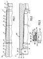
- the male threaded element or pin of Figure 1 is formed at the end of a great length pipe 101 i.e. a pipe of several meters long. It comprises a continuous tapered male thread 3 having a trapezoidal shape. Over a portion 11 of its length, thread 3 is formed by perfect threads having a constant thread height equal to a nominal value between an envelope of thread roots 15 and an envelope of thread crests 16, both being frustoconical. Over the remaining portion 13 of the thread, the threads are imperfect or runout with an envelope of frustoconical thread roots extending that of the perfect threads and an envelope of thread crests constituted by the cylindrical outer peripheral surface 19 of the pipe 101.
- Element 1 comprises a male lip 9 extending between its free end 7 and the thread 3.
- the free end can be defined by a flat surface perpendicular to the axis of the thread.
- it is defined by a concave frustoconical surface 7 the apex half-angle of which is 75°, for example. This surface acts as an axial abutment during makeup of the male element into the female element and its effects have been described in more detail in EP 0 488 912 A.
- the end surface 7 is connected to a frustoconical sealing surface 5, as also described in EP 0 488 912 A.
- element 1 has two successive grooves 51 and 52 obtained by machining, including cylindrical bottom surfaces with the same diameter.
- the non-machined portion subsisting between the two grooves 51 and 52 forms an annular projection (rib) 53.
- the shape of the projection is designed not to cause deleterious fatigue effects.
- One conical surface 54 inclined at about 5° ensures the connection between the cylindrical bottom of the groove 52 to which it is connected via a fillet radius, and the outer cylindrical surface 19.
- the diameter of the thread roots is greater than the bottom of the groove 51, which means that the groove serves not only as a seat for the elastic seal but also as a groove for relaxing stresses in the threads.
- the female threaded element 2 or box shown in Figure 2 is formed at the end of a short tube or sleeve 102 called “coupling" which allows an assembly known as “threaded and coupled” of two great length pipes such as 101, the male threaded elements thereof being made up respectively into two female elements formed at the two ends of the coupling.
- the female threaded element can be formed at the end of a great length pipe to allow it to be coupled to the pipe 101, elements 1 and 2 then forming an integral threaded connection.
- Element 2 as shown comprises a continuous female tapered thread 4 with trapezoidal threads formed exclusively by perfect threads.
- threads 3 and 4 are designed to allow them to cooperate.
- Element 2 has a female lip 10 extending beyond the thread 4 to its free end defined by a flat face 14 perpendicular to the axis of the pipe 102.
- lip 10 In an intermediate region of its length, lip 10 has an inner cylindrical surface 16 with a short axial length and with a diameter that is greater than the diameter of the surface 19 of pipe 101. Either side of surface 16, the lip is hollowed out internally to form an annular groove 18 on the side of the thread 4, and a housing 20 on the side of the free end 14, which are intended to receive respective portions of the sealing ring.
- the thread 4 opens into the groove 18 allowing the tool used to produce the thread to be disengaged.
- Housing 20 has a cylindrical surface 22 with its axis of revolution identical with the longitudinal axis of element 2 and a flat surface 25 perpendicular to the axis and adjacent to the surface 16. Housing 20 opens at end 14 of element 2 via a chamfer 21 intended to facilitate introduction of the male element 1 and of the ring into female element 2.
- female element 2 has a frustoconical abutment surface 8 that can cooperate with the surface 7 of the male element and a frustoconical sealing surface 6 that can cooperate with the sealing surface 5 of the male element.
- the sealing ring 130 shown in Figure 3 is formed from an elastic deformable sealing material, preferably with a low coefficient of friction, for example from polytetrafluoroethylene, polytetrafluoroethylene reinforced with glass fibres, polyamide or a soft metal such as copper.
- Ring 130 has a toroidal form of revolution axially subdivided into three portions, namely a head 136, 137, a body 146 and a retaining lip 143.
- the head is separated into two lips 136 and 137 via an annular groove 135 with a V-shaped profile formed in one end face 133 of the ring.
- Lip 136 is radially outwardly limited by a frustoconical surface 139 the diameter of which decreases from the face 133 towards the body, and which connects with the outer cylindrical surface 131 thereof.
- the body 146 is solid, i.e., does not include any recesses.
- Retaining lip 143 extends axially to the end surface 134 opposite to the face 133, and has an outer cylindrical surface 147 with a diameter that is smaller than that of the surface 131 and which is connected thereto via a flat shoulder 144.
- the ring 130 is radially limited inwardly by a cylindrical surface 132 which extends from the face 133 to the face 134 and is only interrupted by a groove 145 formed in the retaining lip 143 in the vicinity of the body 146, and which has a shape that is adapted to receive the projection (rib) 53 on the male element.
- the sealing ring 134 is initially installed at ambient temperature on the cylindrical bottom of the grooves 51 and 52 of the male element 1, straddling the rib 53. Its designed flexibility allows it to pass over the threads.
- the shape of the groove 145 which is adapted to the rib 53 of the male element, enables the sealing ring 134 to be retained on the male element against translation when screwing up thereof is commenced into the female element.
- the body 146 and lip 143 are then overlapped by the respective cylindrical surfaces 22 and 16 of the female element without stress ( Figures 4 and 5), which has the effect of radially retaining the ring 130 when it is subjected to stresses.
- Axial retention of the ring on the male element then allows the head to penetrate into the housing 20, which necessitates more stress to deform the lip 136 with shrinkage of the groove (recess) 135.
- the ring stops penetrating into the housing 20 when the surface 25 of the housing 20 comes into abutment against the shoulder 144 of the ring, the groove 145 and the rib 53 being located facing the surface 16 ( Figure 6).
- the ring then advances along the male element 1 while the rear portion of the lip 143 is lifted by the rib 53 of the male element 1 and penetrates into the groove 18 of the female element 2 which thus forms a housing for said rear portion.
- this rear portion is axially pinched between the rib 53 and the flank of the groove 18 adjacent to the surface 16, which pinching, along with the cooperation between the shoulders 25 and 144, axially immobilizes the ring 130 with respect to elements 1 and 2.
- lip 137 is raised by the frustoconical surface 54, accentuating compression of the head of the ring and improving the seal at low pressures.
- the recess 135 also ensures a seal at high outer pressures of 150 to 400 bars, for example, the radial component of the forces exerted by the outer pressure on the flanks of the V-shaped recess 135 of the ring increasing the contact pressure resulting from radial interference of the lips 136, 137 between the surface 22 of the female housing and the male surface 54.
Landscapes
- Engineering & Computer Science (AREA)
- General Engineering & Computer Science (AREA)
- Mechanical Engineering (AREA)
- Gasket Seals (AREA)
- Joints With Pressure Members (AREA)
- Non-Disconnectible Joints And Screw-Threaded Joints (AREA)
- Prostheses (AREA)
Claims (26)
- Verfahren zum Herstellen einer rohrförmigen Gewindeverbindung bestehend aus einem rohrförmigen Steckelement (1) mit einem geneigten Außengewinde (3), einem rohrförmigen Buchsenelement (2) mit einem geneigten Innengewinde (4), das mit dem Außengewinde (3) zusammenwirkt, und einem deformierbaren Dichtungsring (130) zur gegenseitigen Fluidverbindung zwischen der Außenseite der rohrförmigen Gewindeverbindung und dem Bereich des Zusammenwirkens der Gewinde, wobei der Dichtungsring in ein erstes ringförmiges Gehäuse (20) eingesetzt wird, dasi) in dem Buchsenelement vorgesehen ist undii) eine Umfangsfläche (21, 22) aufweist, die über wenigstens einen Abschnitt ihrer axialen Länge mit der radialen Außenfläche (131, 139) des Dichtungsrings zusammenwirkt, um letzteren zusammenzudrücken und einen Dichtkontakt zwischen der radialen Außenfläche (139) und der Innenfläche (132) des Dichtungsrings einerseits und der Umfangsfläche (21, 22) des ersten Gehäuses (20) des Buchsenelementes und der zugewandten Fläche (52) des Steckelementes (1) andererseits herzustellen,wobei das freie Ende des Steckelementes (1) mit dem Buchsenelement (2) in Eingriff ist und das Außengewinde in das Innengewinde eingesetzt ist,
dadurch gekennzeichnet, dass
das erste Gehäuse die Form einer Vergrößerung der axialen Bohrung des Buchsenelementes aufweist, das sich axial von dem freien Ende des Buchsenelementes (14) zu einer Schulter (25) gegenüber dem freien Ende erstreckt, und dass:- der Dichtungsring um das Steckelement (1) über sein Gewinde (3) in Bezug auf sein freies Ende (7) hinaus angeordnet ist, wobei der Dichtungsring (130) einen Körper und eine Haltelippe (143) mit einer radialen Dicke aufweist, die geringer als diejenige des Körpers ist, die sich axial in Richtung des Gewindes (3) von einer Schulter (144) erstreckt, die den Körper definiert und einen verdünnten Bereich (145) in der Nähe des Körpers aufweist, wobei der verdünnte Bereich (145) mit einer ringförmigen Rippe (53) in Kontakt steht, die als ein radialer Vorsprung auf dem Steckelement vorgesehen ist; und- während der Montage der Dichtungsring nach und nach in das erste ringförmige Gehäuse (20) eingeführt wird, der Körper (146) dann entlang dem Steckelement mittels der Schulter (25) des ersten Gehäuses (20) des Buchsenelementes (2) gestoßen wird, nachdem die beiden Schultern (25, 144) aneinander anliegen, und die ringförmige Rippe (53) des Steckelementes (1) in Kontakt mit der Haltelippe (143) am Ende der Montage über den verdünnten Bereich (145) hinaus in Kontakt kommt, um die Haltelippe in ein zweites ringförmiges Gehäuse (18), das in dem Buchsenelement (2) in einem axialen Abstand zu dem ersten Gehäuse (20) ausgebildet ist, eindringen zu lassen, um einen axialen Rückhalt des Dichtungsringes durch das Buchsenelement sicherzustellen. - Verfahren nach Anspruch 1, bei dem der Dichtungsring aus einem Material ausgebildet ist, das aus synthetischen Materialien, verformbaren Metallen und Verbundmaterialien ausgewählt ist.
- Verfahren nach Anspruch 1 oder 2, bei dem der Dichtungsring aus einem Material mit einem geringen Reibungskoeffizienten in Bezug auf das Material des Steckelementes ausgebildet ist.
- Verfahren nach einem der vorhergehenden Ansprüche, bei dem der Dichtungsring aus gefülltem oder nicht gefülltem Polytetrafluoroethylen ausgebildet ist.
- Verfahren nach einem der vorhergehenden Ansprüche, bei dem am Ende der Montage die ringförmige Rippe (53) des Steckelementes (1) die Haltelippe (143) in Kontakt mit der Flanke des zweiten ringförmigen Gehäuses (18) des Buchsenelementes (2) bringt, die an der Seite der Schulter (25) des ersten Gehäuses (20) angeordnet ist.
- Verfahren nach einem der vorhergehenden Ansprüche, bei dem das Außengewinde gegenüber dem freien Ende (7) des Steckelementes Auslaufgewindegänge (13) aufweist, deren radiale Höhe im allgemeinen von einem Nominalwert auf den Wert 0 abnimmt.
- Verfahren nach einem der vorhergehenden Ansprüche, bei dem die Umfangsfläche (21, 22) des ersten Gehäuses (20) eine im wesentlichen zylindrische Fläche (22) neben seiner Schulter (25) mit einem Durchmesser aufweist, der im wesentlichen dem Durchmesser einer im wesentlichen zylindrischen Außenfläche (131) des Körpers entspricht.
- Verfahren nach einem der vorhergehenden Ansprüche, bei dem die Umfangsfläche (21, 22) des ersten Gehäuses (20) eine aufgeweitete Fläche (21) nahe dem freien Ende (14) des Buchsenelementes aufweist.
- Verfahren nach einem der vorhergehenden Ansprüche, bei dem das Steckelement (1) eine axiale Anschlagfläche (7) nahe seines freien Endes aufweist, wobei die Fläche mit einer axialen Anschlagfläche (8) des Buchsenelementes (2) zusammenwirken kann, um die Montage zu begrenzen.
- Verfahren nach einem der vorhergehenden Ansprüche, bei dem der verdünnte Bereich durch eine ringförmige Nut (145) definiert ist, die in der radialen Innenfläche (132) des Dichtungsringes (130) ausgebildet ist und welche die ringförmige Rippe (53) des Steckelementes aufnehmen kann, um den Dichtungsring (130) in Position zu halten, nachdem dieser auf dem Steckelement positioniert ist.
- Verfahren nach Anspruch 10, bei dem vor dem Zusammenbau die radiale Innenfläche (132) des Dichtungsringes (130) einen im wesentlichen konstanten Durchmesser mit Ausnahme der ringförmigen Nut (145) aufweist.
- Verfahren nach Anspruch 11, abhängig von Anspruch 10, bei dem die ringförmige Rippe (53) durch zwei ringförmige Nuten (51, 52) mit Bodenflächen definiert ist, die derart hergestellt sind, dass sie im wesentlichen zylindrisch sind und den gleichen Durchmesser aufweisen, um mit der radialen Innenfläche (132) zusammenzuwirken.
- Verfahren nach Anspruch 12, bei dem die ringförmige Nut (52), welche die ringförmige Rippe (53) definiert, die gegenüber dem freien Ende (7) des Buchsenelementes angeordnet ist, eine Flanke (54) gegenüber der Rippe (53) aufweist, die geringfügig in Bezug auf die Achse der Verbindung geneigt ist, die am Ende der Montage mit der radialen Innenfläche (132) des Dichtungsringes in Kontakt kommt, um den Druck zwischen dem Dichtungsring und der Dichtung der Verbindung zu erhöhen.
- Verfahren nach einem der vorhergehenden Ansprüche, bei dem der Körper (146) massiv ist und mit einem Kopf (136, 137) verbunden ist, der eine radiale Dicke aufweist, die größer als die des Körpers ist, und sich axial von dem Körper gegenüber der Haltelippe erstreckt und eine Aussparung (135) aufweist, die zwischen seiner radialen Außenfläche (139) und seiner Innenfläche (132) angeordnet ist.
- Verfahren nach Anspruch 14, bei dem das radiale Pressen des Dichtungsringes das radiale Pressen des Kopfes (136, 137) und seiner Aussparung (135) umfasst.
- Verfahren nach Anspruch 14 oder Anspruch 15, bei dem die Aussparung die Form einer ringförmigen Nut (135) aufweist, die den Kopf radial in zwei Bereiche (136, 137) und entsprechend benachbart zu der radialen Außenfläche (139) und der radialen Innenfläche (132) trennt.
- Verfahren nach Anspruch 16, abhängig von Anspruch 7, bei dem der Bereich (136) des Kopfes nahe der radialen Außenfläche (139) auf der im Wesentlichen zylindrischen Fläche (22) des ersten Gehäuses ruht, wenn die Montage abgeschlossen ist.
- Verfahren nach Anspruch 16 oder 17, bei dem die ringförmige Nut (135) ein V-förmiges Profil aufweist.
- Verfahren nach einem der Ansprüche 14 bis 18, bei dem sich die Außenfläche (139) des Kopfes nach und nach von einer im wesentlichen zylindrischen Fläche (131) des Körpers zu dem freien Ende des Kopfes (136, 137) aufweitet.
- Verfahren nach einem der vorhergehenden Ansprüche, bei dem das erste Gehäuse und das zweite Gehäuse (20, 18) des Buchsenelementes (2) gemeinsam einen ringförmigen Vorsprung (16) mit einem minimalen Durchmesser definieren, der im wesentlichen gleich dem maximalen Außendurchmesser der Haltelippe ist, um letztere während der Montage zu überlappen.
- Verfahren nach Anspruch 20, bei dem der ringförmige Vorsprung (16) zu Beginn des Pressens des Dichtungsringes (130) über die ringförmige Rippe (53) hinaus auf dem Steckelement (1) an der freiendigen (7) Seite des Steckelementes angeordnet ist.
- Verfahren nach Anspruch 20 oder 21, bei dem der ringförmige Vorsprung (16) mit der ringförmige Rippe (53) des Steckelementes (1) fluchtend angeordnet ist, wenn die beiden Schultern (25, 144) gegenseitig aneinander anliegen.
- Verfahren nach einem der vorhergehenden Ansprüche, bei dem das zweite ringförmige Gehäuse des Buchsenelementes (2) die Form einer Nut (18) aufweist, in einer deren Flanken sich das Innengewinde (4) öffnet.
- Deformierbarer Dichtungsring (130) zur Verwendung bei dem Verfahren nach einem der vorhergehenden Ansprüche, der einen massiven Körper (146) und eine Haltelippe (143) umfasst, die eine radiale Dicke aufweist, die geringer als diejenige des Körpers ist, und die sich axial von einer den Körper definierenden Schulter (144) erstreckt und einen verdünnten Bereich in der Nähe des Körpers aufweist, der durch eine ringförmige Nut (145) definiert ist, der in der radialen Innenfläche (132) des Dichtungsringes (130) ausgebildet ist, wobei der Dichtungsring (130) ferner einen Kopf (136, 137) aufweist, der mit dem Körper (146) verbunden ist, sich axial von dem Körper gegenüber der Haltelippe erstreckt und eine radiale Dicke aufweist, die größer als diejenige des Körpers ist,
dadurch gekennzeichnet, dass
der Kopf (136, 137) eine Aussparung (135) aufweist, die zwischen seiner radialen Außenfläche (139) und seiner Innenfläche (132) angeordnet ist. - Ein Satz zur Verwendung bei dem Verfahren gemäß einem der Ansprüche 1 bis 23, der aufweist:- einen deformierbaren Dichtungsring (130), der einen Körper (146) und eine Haltelippe (143) umfasst, die eine radiale Dicke aufweist, die geringer als diejenige des Körpers ist, und die sich axial von einer körperdefinierenden Schulter (144) erstreckt und einen verdünnten Bereich in der Nähe des Körpers aufweist;- ein rohrförmiges Steckelement (1) mit einem geneigten Außengewinde (3) und einer radial über das Gewinde (3) in Bezug auf sein freies Ende (7) vorstehenden ringförmigen Rippe (53); und- ein rohrförmiges Buchsenelement (2) mit einem geneigten Innengewinde (4), das mit dem Außengewinde (3) zusammenwirken kann, einem ersten ringförmigen Gehäuse (20), das in dem Buchsenelement in Form einer Vergrößerung seiner axialen Bohrung vorgesehen ist, sich axial von seinem freien Ende (14) zu einer Schulter (25) erstreckt und eine Umfangsfläche (22) neben der Schulter (25) aufweist, und einem zweiten ringförmigen Gehäuse (18), das in einem axialen Abstand von dem ersten Gehäuse (20) angeordnet ist.
- Rohrförmige Gewindeverbindung, die mit Hilfe des Verfahrens nach einem der Ansprüche 1 bis 23 erzielt wird, mit einem Steckelement (1), das ein geneigtes Außengewinde (3) aufweist, einem rohrförmigen Buchsenelement (2), das ein geneigtes Innengewinde (4) aufweist, das mit dem Außengewinde (3) zusammenwirkt, und einem deformierbaren Dichtungsring (130), der zwischen dem Steckelement und dem Buchsenelement zur gegenseitigen Fluidkommunikation zwischen der Außenseite der rohrförmigen Gewindeverbindung und dem Bereich des Zusammenwirkens der Gewinde angeordnet ist, wobei der Dichtungsring (130) axial zwischen den Gewinden und dem freien Ende des Buchsenelementes (2) angeordnet ist und einen Körper (146) und eine Haltelippe (143) aufweist, die eine radiale Dicke hat, die geringer als diejenige des Körpers ist, die sich axial in Richtung der Gewinde (3, 4) von einer den Körper definierenden Schulter (144) erstreckt und einen verdünnten Bereich (145) in der Nähe des Körpers umfasst, wobei sich der Körper, der in einem ersten ringförmigen Gehäuse (20) aufgenommen ist, das in dem Buchsenelement in der Form einer Vergrößerung seiner axialen Bohrung vorgesehen ist, axial von seinem freien Ende (14) zu einer Schulter (25) erstreckt und eine Umfangsfläche (22) nahe der Schulter (25) aufweist, die in Kontakt mit dem Dichtungsring zum radialen Pressen desselben steht, eine radial vorstehende ringförmige Rippe (53), die auf dem Steckelement, das mit der Haltelippe (143) in Kontakt steht, über den verdünnten Bereich (145) hinaus vorgesehen ist, um die Haltelippe dazu zu bringen, in ein zweites ringförmiges Gehäuse (18) vorzudringen, das in dem Buchsenelement (2) in einem axialen Abstand von dem ersten Gehäuse (20) ausgebildet ist, um einen axialen Rückhalt des Dichtungsringes durch das Buchsenelement sicherzustellen.
Applications Claiming Priority (3)
| Application Number | Priority Date | Filing Date | Title |
|---|---|---|---|
| FR0215541 | 2002-12-09 | ||
| FR0215541A FR2848282B1 (fr) | 2002-12-09 | 2002-12-09 | Procede de realisation d'un joint filete tubulaire etanche vis-a-vis de l'exterieur |
| PCT/EP2003/014843 WO2004053376A1 (en) | 2002-12-09 | 2003-11-28 | Method for producing a threaded tubular connection sealed to the outside |
Publications (2)
| Publication Number | Publication Date |
|---|---|
| EP1570200A1 EP1570200A1 (de) | 2005-09-07 |
| EP1570200B1 true EP1570200B1 (de) | 2007-01-17 |
Family
ID=32320113
Family Applications (1)
| Application Number | Title | Priority Date | Filing Date |
|---|---|---|---|
| EP03789406A Expired - Lifetime EP1570200B1 (de) | 2002-12-09 | 2003-11-28 | Verfahren zum herstellen einer von aussen abgedichteten gewinderohrkupplung |
Country Status (16)
| Country | Link |
|---|---|
| US (1) | US7475476B2 (de) |
| EP (1) | EP1570200B1 (de) |
| JP (1) | JP4201766B2 (de) |
| CN (1) | CN100485243C (de) |
| AR (1) | AR042323A1 (de) |
| AT (1) | ATE352005T1 (de) |
| AU (1) | AU2003293992A1 (de) |
| BR (1) | BR0317074A (de) |
| CA (1) | CA2508461C (de) |
| DE (1) | DE60311308T2 (de) |
| ES (1) | ES2278217T3 (de) |
| FR (1) | FR2848282B1 (de) |
| MX (1) | MXPA05006112A (de) |
| PL (1) | PL207607B1 (de) |
| RU (1) | RU2301371C2 (de) |
| WO (1) | WO2004053376A1 (de) |
Families Citing this family (30)
| Publication number | Priority date | Publication date | Assignee | Title |
|---|---|---|---|---|
| US7828158B2 (en) * | 2005-07-14 | 2010-11-09 | Displays Plus, Inc. | Merchandise dispensing apparatus providing theft deterrence |
| US20080000851A1 (en) * | 2006-06-02 | 2008-01-03 | Rohm And Haas Electronic Materials Llc | Apparatus with fillet radius joints |
| FR2904031B1 (fr) * | 2006-07-20 | 2014-03-07 | Vallourec Mannesmann Oil & Gas | Element male, pour un composant de forage, a butee externe et butee interne adaptee au refacage sans perte de couple de resistance, et ensemble de composants de forage associe. |
| EP2006589B1 (de) * | 2007-06-22 | 2011-08-31 | Tenaris Connections Aktiengesellschaft | Gewindeverbindungsstück mit aktivierbarer Dichtung |
| EP2009340B1 (de) * | 2007-06-27 | 2010-12-08 | Tenaris Connections Aktiengesellschaft | Gewindeverbindung mit unter Druck setzbarer Dichtung |
| EP2017507B1 (de) | 2007-07-16 | 2016-06-01 | Tenaris Connections Limited | Gewindeverbindungsstück mit elastischem Dichtungsring |
| DE602007013892D1 (de) | 2007-08-24 | 2011-05-26 | Tenaris Connections Ag | Gewindeverbindungsstück mit hoher Radiallast und unterschiedlich behandelten Oberflächen |
| DE602007008890D1 (de) | 2007-08-24 | 2010-10-14 | Tenaris Connections Ag | Verfahren zur Erhöhung der Ermüdungsbeständigkeit einer Schraubverbindung |
| ATE471433T1 (de) * | 2008-02-29 | 2010-07-15 | Tenaris Connections Ag | Gewindeverbindungsstück mit verbesserten elastischen dichtungsringen |
| EP2243920A1 (de) | 2009-04-22 | 2010-10-27 | Tenaris Connections Aktiengesellschaft | Gewindeverbindung für Röhren, Leitungen und dergleichen |
| EP2325435B2 (de) | 2009-11-24 | 2020-09-30 | Tenaris Connections B.V. | Verschraubung für [ultrahoch] abgedichteten internen und externen Druck |
| EP2372208B1 (de) * | 2010-03-25 | 2013-05-29 | Tenaris Connections Limited | Gewindeverbindung mit elastomerischem Dichtflansch |
| EP2372211B1 (de) | 2010-03-26 | 2015-06-03 | Tenaris Connections Ltd. | Dünnwandige Rohrverbindung und Verfahren zum Verbinden eines ersten Rohres mit einem zweiten Rohr |
| US9163296B2 (en) | 2011-01-25 | 2015-10-20 | Tenaris Coiled Tubes, Llc | Coiled tube with varying mechanical properties for superior performance and methods to produce the same by a continuous heat treatment |
| CN102644444A (zh) * | 2012-04-24 | 2012-08-22 | 山东东宝钢管有限公司 | 双密封防腐注水井油管 |
| JP6204496B2 (ja) | 2013-01-11 | 2017-09-27 | テナリス・コネクシヨンズ・ベー・ブイ | 耐ゴーリング性ドリルパイプツールジョイントおよび対応するドリルパイプ |
| US9803256B2 (en) | 2013-03-14 | 2017-10-31 | Tenaris Coiled Tubes, Llc | High performance material for coiled tubing applications and the method of producing the same |
| EP2789701A1 (de) | 2013-04-08 | 2014-10-15 | DALMINE S.p.A. | Hochfeste mittelwandige vergütete und nahtlose Stahlrohre und entsprechendes Verfahren zur Herstellung der Stahlrohre |
| EP2789700A1 (de) | 2013-04-08 | 2014-10-15 | DALMINE S.p.A. | Dickwandige vergütete und nahtlose Stahlrohre und entsprechendes Verfahren zur Herstellung der Stahlrohre |
| CN103292076A (zh) * | 2013-06-04 | 2013-09-11 | 无锡金顶石油管材配件制造有限公司 | 一种锥口结构石油管路 |
| EP2885440B1 (de) | 2013-06-25 | 2016-03-23 | Tenaris Connections Ltd. | Hitzebeständiger stahl mit hohem chromgehalt |
| CN104765898B (zh) * | 2014-01-07 | 2019-03-15 | 北京玻钢院复合材料有限公司 | 一种锥环与密封环的组合结构及其设计方法 |
| FR3027338B1 (fr) | 2014-10-16 | 2016-12-02 | Vallourec Oil & Gas France | Connexion polyvalente etanche a double butee |
| CN104613211A (zh) * | 2015-01-23 | 2015-05-13 | 苏州巨瀚阀门有限公司 | 一种防泄漏型排气阀 |
| US20160305192A1 (en) | 2015-04-14 | 2016-10-20 | Tenaris Connections Limited | Ultra-fine grained steels having corrosion-fatigue resistance |
| US11124852B2 (en) | 2016-08-12 | 2021-09-21 | Tenaris Coiled Tubes, Llc | Method and system for manufacturing coiled tubing |
| US10434554B2 (en) | 2017-01-17 | 2019-10-08 | Forum Us, Inc. | Method of manufacturing a coiled tubing string |
| EP3572612B1 (de) * | 2018-05-25 | 2020-10-07 | Vallourec Oil And Gas France | Rohrgewindeanschluss |
| PL3572611T3 (pl) * | 2018-05-25 | 2021-07-05 | Vallourec Oil And Gas France | Gwintowane połączenie rurowe |
| GB2606951A (en) * | 2020-01-20 | 2022-11-23 | United Drilling Tools Ltd | Metal seal weld-on connector for conductor casing |
Family Cites Families (13)
| Publication number | Priority date | Publication date | Assignee | Title |
|---|---|---|---|---|
| GB880283A (en) * | 1959-08-12 | 1961-10-18 | Gilbert Thomas Lyon | Pipe coupling for fluid pressure systems |
| US3150889A (en) * | 1960-10-11 | 1964-09-29 | Gray Tool Co | Coupling with rigidly fixed sealing ring |
| US4706997A (en) | 1982-05-19 | 1987-11-17 | Carstensen Kenneth J | Coupling for tubing or casing and method of assembly |
| US4878285A (en) * | 1982-05-19 | 1989-11-07 | Carstensen Kenneth J | Method of assembling coupling to tubing or casting |
| EP0094509B1 (de) | 1982-05-19 | 1987-07-15 | Kenneth J. Carstensen | Steig- oder Futterrohrkupplung und Verfahren zum Zusammenfügen |
| SU1555587A1 (ru) * | 1988-01-06 | 1990-04-07 | Горловский филиал Донецкого политехнического института | Устройство дл герметизации резьбовых соединений |
| DE8805087U1 (de) * | 1988-04-16 | 1988-06-01 | Schaubstahl-Silobau und Metallwaren GmbH & Co KG, 5910 Kreuztal | Pumpensteigeleitung |
| US5137310A (en) | 1990-11-27 | 1992-08-11 | Vallourec Industries | Assembly arrangement using frustoconical screwthreads for tubes |
| DE4317591C1 (de) | 1993-05-24 | 1994-05-19 | Mannesmann Ag | Gasdichte Ölfeldrohr-Verbindung |
| JPH07139666A (ja) | 1993-11-16 | 1995-05-30 | Kawasaki Steel Corp | 油井管用ネジ継手 |
| US5687999A (en) | 1995-10-03 | 1997-11-18 | Vallourec Oil & Gas | Threaded joint for tubes |
| US6857668B2 (en) * | 2000-10-04 | 2005-02-22 | Grant Prideco, L.P. | Replaceable corrosion seal for threaded connections |
| US6550822B2 (en) * | 2001-04-25 | 2003-04-22 | G. B. Tubulars, Inc. | Threaded coupling with water exclusion seal system |
-
2002
- 2002-12-09 FR FR0215541A patent/FR2848282B1/fr not_active Expired - Fee Related
-
2003
- 2003-11-28 CN CNB2003801055105A patent/CN100485243C/zh not_active Expired - Fee Related
- 2003-11-28 PL PL377349A patent/PL207607B1/pl unknown
- 2003-11-28 ES ES03789406T patent/ES2278217T3/es not_active Expired - Lifetime
- 2003-11-28 BR BR0317074-8A patent/BR0317074A/pt not_active IP Right Cessation
- 2003-11-28 CA CA2508461A patent/CA2508461C/en not_active Expired - Fee Related
- 2003-11-28 RU RU2005121529/06A patent/RU2301371C2/ru not_active IP Right Cessation
- 2003-11-28 AT AT03789406T patent/ATE352005T1/de active
- 2003-11-28 DE DE60311308T patent/DE60311308T2/de not_active Expired - Lifetime
- 2003-11-28 JP JP2004558084A patent/JP4201766B2/ja not_active Expired - Fee Related
- 2003-11-28 US US10/537,903 patent/US7475476B2/en not_active Expired - Lifetime
- 2003-11-28 MX MXPA05006112A patent/MXPA05006112A/es active IP Right Grant
- 2003-11-28 EP EP03789406A patent/EP1570200B1/de not_active Expired - Lifetime
- 2003-11-28 AU AU2003293992A patent/AU2003293992A1/en not_active Abandoned
- 2003-11-28 WO PCT/EP2003/014843 patent/WO2004053376A1/en not_active Ceased
- 2003-12-05 AR ARP030104504A patent/AR042323A1/es active IP Right Grant
Also Published As
| Publication number | Publication date |
|---|---|
| ES2278217T3 (es) | 2007-08-01 |
| RU2005121529A (ru) | 2006-04-10 |
| DE60311308D1 (de) | 2007-03-08 |
| WO2004053376A1 (en) | 2004-06-24 |
| AU2003293992A8 (en) | 2004-06-30 |
| AU2003293992A1 (en) | 2004-06-30 |
| RU2301371C2 (ru) | 2007-06-20 |
| JP2006509167A (ja) | 2006-03-16 |
| BR0317074A (pt) | 2005-10-25 |
| CA2508461A1 (en) | 2004-06-24 |
| PL207607B1 (pl) | 2011-01-31 |
| PL377349A1 (pl) | 2006-01-23 |
| DE60311308T2 (de) | 2007-08-30 |
| JP4201766B2 (ja) | 2008-12-24 |
| AR042323A1 (es) | 2005-06-15 |
| ATE352005T1 (de) | 2007-02-15 |
| US20070039149A1 (en) | 2007-02-22 |
| CN100485243C (zh) | 2009-05-06 |
| FR2848282B1 (fr) | 2006-12-29 |
| MXPA05006112A (es) | 2005-12-14 |
| US7475476B2 (en) | 2009-01-13 |
| FR2848282A1 (fr) | 2004-06-11 |
| EP1570200A1 (de) | 2005-09-07 |
| CN1723357A (zh) | 2006-01-18 |
| CA2508461C (en) | 2011-02-08 |
Similar Documents
| Publication | Publication Date | Title |
|---|---|---|
| EP1570200B1 (de) | Verfahren zum herstellen einer von aussen abgedichteten gewinderohrkupplung | |
| CA2185251C (en) | Threaded joint for tubes | |
| US7621034B2 (en) | Tubular threaded joint which is impervious to the external environment | |
| US4537429A (en) | Tubular connection with cylindrical and tapered stepped threads | |
| EP0897504B1 (de) | Gestängeverschraubung mit zwei angepassten schultern | |
| US4712815A (en) | Metal-to-metal wedge thread coupling connector | |
| US4629224A (en) | Tubular connection | |
| EP0152406B1 (de) | Rohrverbindung | |
| CN100392309C (zh) | 带有塑性膨胀的密封管状接头的实现方法 | |
| US9863560B2 (en) | Expansible threaded joint and method for making same | |
| US7513534B2 (en) | Fatigue-resistant threaded component for a tubular threaded joint | |
| CA3145351C (en) | THREADED FITTING FOR OIL WELL CASING STANDARD | |
| EP3622209B1 (de) | Krummliniges dichtungssystem | |
| CA3145349C (en) | Threaded connection having a dissymmetrical helical profile | |
| CN107075925B (zh) | 多用途双抵接部密封连接 | |
| WO1984004352A1 (en) | Tubular connection with cylindrical and tapered stepped threads | |
| WO2002035128A2 (en) | Threaded pipe joint |
Legal Events
| Date | Code | Title | Description |
|---|---|---|---|
| PUAI | Public reference made under article 153(3) epc to a published international application that has entered the european phase |
Free format text: ORIGINAL CODE: 0009012 |
|
| 17P | Request for examination filed |
Effective date: 20050602 |
|
| AK | Designated contracting states |
Kind code of ref document: A1 Designated state(s): AT BE BG CH CY CZ DE DK EE ES FI FR GB GR HU IE IT LI LU MC NL PT RO SE SI SK TR |
|
| AX | Request for extension of the european patent |
Extension state: AL LT LV MK |
|
| DAX | Request for extension of the european patent (deleted) | ||
| GRAP | Despatch of communication of intention to grant a patent |
Free format text: ORIGINAL CODE: EPIDOSNIGR1 |
|
| GRAS | Grant fee paid |
Free format text: ORIGINAL CODE: EPIDOSNIGR3 |
|
| GRAA | (expected) grant |
Free format text: ORIGINAL CODE: 0009210 |
|
| AK | Designated contracting states |
Kind code of ref document: B1 Designated state(s): AT BE BG CH CY CZ DE DK EE ES FI FR GB GR HU IE IT LI LU MC NL PT RO SE SI SK TR |
|
| PG25 | Lapsed in a contracting state [announced via postgrant information from national office to epo] |
Ref country code: SI Free format text: LAPSE BECAUSE OF FAILURE TO SUBMIT A TRANSLATION OF THE DESCRIPTION OR TO PAY THE FEE WITHIN THE PRESCRIBED TIME-LIMIT Effective date: 20070117 Ref country code: FI Free format text: LAPSE BECAUSE OF FAILURE TO SUBMIT A TRANSLATION OF THE DESCRIPTION OR TO PAY THE FEE WITHIN THE PRESCRIBED TIME-LIMIT Effective date: 20070117 Ref country code: NL Free format text: LAPSE BECAUSE OF FAILURE TO SUBMIT A TRANSLATION OF THE DESCRIPTION OR TO PAY THE FEE WITHIN THE PRESCRIBED TIME-LIMIT Effective date: 20070117 Ref country code: LI Free format text: LAPSE BECAUSE OF FAILURE TO SUBMIT A TRANSLATION OF THE DESCRIPTION OR TO PAY THE FEE WITHIN THE PRESCRIBED TIME-LIMIT Effective date: 20070117 Ref country code: DK Free format text: LAPSE BECAUSE OF FAILURE TO SUBMIT A TRANSLATION OF THE DESCRIPTION OR TO PAY THE FEE WITHIN THE PRESCRIBED TIME-LIMIT Effective date: 20070117 Ref country code: CH Free format text: LAPSE BECAUSE OF FAILURE TO SUBMIT A TRANSLATION OF THE DESCRIPTION OR TO PAY THE FEE WITHIN THE PRESCRIBED TIME-LIMIT Effective date: 20070117 |
|
| REG | Reference to a national code |
Ref country code: GB Ref legal event code: FG4D |
|
| REG | Reference to a national code |
Ref country code: CH Ref legal event code: EP Ref country code: RO Ref legal event code: EPE |
|
| REG | Reference to a national code |
Ref country code: IE Ref legal event code: FG4D |
|
| REF | Corresponds to: |
Ref document number: 60311308 Country of ref document: DE Date of ref document: 20070308 Kind code of ref document: P |
|
| PG25 | Lapsed in a contracting state [announced via postgrant information from national office to epo] |
Ref country code: SE Free format text: LAPSE BECAUSE OF FAILURE TO SUBMIT A TRANSLATION OF THE DESCRIPTION OR TO PAY THE FEE WITHIN THE PRESCRIBED TIME-LIMIT Effective date: 20070417 |
|
| PG25 | Lapsed in a contracting state [announced via postgrant information from national office to epo] |
Ref country code: BG Free format text: LAPSE BECAUSE OF EXPIRATION OF PROTECTION Effective date: 20070418 |
|
| PG25 | Lapsed in a contracting state [announced via postgrant information from national office to epo] |
Ref country code: PT Free format text: LAPSE BECAUSE OF FAILURE TO SUBMIT A TRANSLATION OF THE DESCRIPTION OR TO PAY THE FEE WITHIN THE PRESCRIBED TIME-LIMIT Effective date: 20070618 |
|
| NLV1 | Nl: lapsed or annulled due to failure to fulfill the requirements of art. 29p and 29m of the patents act | ||
| ET | Fr: translation filed | ||
| REG | Reference to a national code |
Ref country code: CH Ref legal event code: PL |
|
| REG | Reference to a national code |
Ref country code: ES Ref legal event code: FG2A Ref document number: 2278217 Country of ref document: ES Kind code of ref document: T3 |
|
| PLBE | No opposition filed within time limit |
Free format text: ORIGINAL CODE: 0009261 |
|
| STAA | Information on the status of an ep patent application or granted ep patent |
Free format text: STATUS: NO OPPOSITION FILED WITHIN TIME LIMIT |
|
| PG25 | Lapsed in a contracting state [announced via postgrant information from national office to epo] |
Ref country code: SK Free format text: LAPSE BECAUSE OF FAILURE TO SUBMIT A TRANSLATION OF THE DESCRIPTION OR TO PAY THE FEE WITHIN THE PRESCRIBED TIME-LIMIT Effective date: 20070117 |
|
| 26N | No opposition filed |
Effective date: 20071018 |
|
| PG25 | Lapsed in a contracting state [announced via postgrant information from national office to epo] |
Ref country code: BE Free format text: LAPSE BECAUSE OF FAILURE TO SUBMIT A TRANSLATION OF THE DESCRIPTION OR TO PAY THE FEE WITHIN THE PRESCRIBED TIME-LIMIT Effective date: 20070117 |
|
| PG25 | Lapsed in a contracting state [announced via postgrant information from national office to epo] |
Ref country code: GR Free format text: LAPSE BECAUSE OF FAILURE TO SUBMIT A TRANSLATION OF THE DESCRIPTION OR TO PAY THE FEE WITHIN THE PRESCRIBED TIME-LIMIT Effective date: 20070418 |
|
| PG25 | Lapsed in a contracting state [announced via postgrant information from national office to epo] |
Ref country code: MC Free format text: LAPSE BECAUSE OF NON-PAYMENT OF DUE FEES Effective date: 20071130 |
|
| PG25 | Lapsed in a contracting state [announced via postgrant information from national office to epo] |
Ref country code: IE Free format text: LAPSE BECAUSE OF NON-PAYMENT OF DUE FEES Effective date: 20071128 |
|
| PG25 | Lapsed in a contracting state [announced via postgrant information from national office to epo] |
Ref country code: EE Free format text: LAPSE BECAUSE OF FAILURE TO SUBMIT A TRANSLATION OF THE DESCRIPTION OR TO PAY THE FEE WITHIN THE PRESCRIBED TIME-LIMIT Effective date: 20070117 |
|
| REG | Reference to a national code |
Ref country code: ES Ref legal event code: FD2A Effective date: 20071129 |
|
| PG25 | Lapsed in a contracting state [announced via postgrant information from national office to epo] |
Ref country code: ES Free format text: LAPSE BECAUSE OF NON-PAYMENT OF DUE FEES Effective date: 20071129 |
|
| PG25 | Lapsed in a contracting state [announced via postgrant information from national office to epo] |
Ref country code: CY Free format text: LAPSE BECAUSE OF FAILURE TO SUBMIT A TRANSLATION OF THE DESCRIPTION OR TO PAY THE FEE WITHIN THE PRESCRIBED TIME-LIMIT Effective date: 20070117 |
|
| PG25 | Lapsed in a contracting state [announced via postgrant information from national office to epo] |
Ref country code: LU Free format text: LAPSE BECAUSE OF NON-PAYMENT OF DUE FEES Effective date: 20071128 |
|
| PG25 | Lapsed in a contracting state [announced via postgrant information from national office to epo] |
Ref country code: HU Free format text: LAPSE BECAUSE OF FAILURE TO SUBMIT A TRANSLATION OF THE DESCRIPTION OR TO PAY THE FEE WITHIN THE PRESCRIBED TIME-LIMIT Effective date: 20070718 Ref country code: TR Free format text: LAPSE BECAUSE OF FAILURE TO SUBMIT A TRANSLATION OF THE DESCRIPTION OR TO PAY THE FEE WITHIN THE PRESCRIBED TIME-LIMIT Effective date: 20070117 |
|
| REG | Reference to a national code |
Ref country code: GB Ref legal event code: 732E Free format text: REGISTERED BETWEEN 20131010 AND 20131016 |
|
| REG | Reference to a national code |
Ref country code: FR Ref legal event code: TQ Owner name: NIPPON STEEL & SUMITOMO METAL CORPORATION, JP Effective date: 20131108 Ref country code: FR Ref legal event code: TQ Owner name: VALLOUREC MANNESMANN OIL GAS FR, FR Effective date: 20131108 |
|
| REG | Reference to a national code |
Ref country code: DE Ref legal event code: R082 Ref document number: 60311308 Country of ref document: DE Representative=s name: GRUENECKER, KINKELDEY, STOCKMAIR & SCHWANHAEUS, DE Effective date: 20140403 Ref country code: DE Ref legal event code: R081 Ref document number: 60311308 Country of ref document: DE Owner name: VALLOUREC MANNESMANN OIL & GAS FRANCE, FR Free format text: FORMER OWNER: VALLOUREC MANNESMANN OIL & GAS , SUMITOMO METAL INDUSTRIES, LTD., , JP Effective date: 20140403 Ref country code: DE Ref legal event code: R081 Ref document number: 60311308 Country of ref document: DE Owner name: NIPPON STEEL & SUMITOMO METAL CORPORATION, JP Free format text: FORMER OWNER: VALLOUREC MANNESMANN OIL & GAS , SUMITOMO METAL INDUSTRIES, LTD., , JP Effective date: 20140403 Ref country code: DE Ref legal event code: R081 Ref document number: 60311308 Country of ref document: DE Owner name: NIPPON STEEL & SUMITOMO METAL CORPORATION, JP Free format text: FORMER OWNERS: VALLOUREC MANNESMANN OIL & GAS FRANCE, AULNOYE-AYMERIES, FR; SUMITOMO METAL INDUSTRIES, LTD., OSAKA, JP Effective date: 20140403 Ref country code: DE Ref legal event code: R082 Ref document number: 60311308 Country of ref document: DE Representative=s name: GRUENECKER PATENT- UND RECHTSANWAELTE PARTG MB, DE Effective date: 20140403 Ref country code: DE Ref legal event code: R081 Ref document number: 60311308 Country of ref document: DE Owner name: VALLOUREC MANNESMANN OIL & GAS FRANCE, FR Free format text: FORMER OWNERS: VALLOUREC MANNESMANN OIL & GAS FRANCE, AULNOYE-AYMERIES, FR; SUMITOMO METAL INDUSTRIES, LTD., OSAKA, JP Effective date: 20140403 |
|
| REG | Reference to a national code |
Ref country code: FR Ref legal event code: CD Owner name: VALLOUREC OIL AND GAS FRANCE, FR Effective date: 20150206 Ref country code: FR Ref legal event code: CD Owner name: NIPPON STEEL & SUMITOMO METAL CORPORATION, JP Effective date: 20150206 |
|
| REG | Reference to a national code |
Ref country code: FR Ref legal event code: PLFP Year of fee payment: 13 |
|
| REG | Reference to a national code |
Ref country code: FR Ref legal event code: PLFP Year of fee payment: 14 |
|
| PGFP | Annual fee paid to national office [announced via postgrant information from national office to epo] |
Ref country code: CZ Payment date: 20161125 Year of fee payment: 14 |
|
| REG | Reference to a national code |
Ref country code: FR Ref legal event code: PLFP Year of fee payment: 15 |
|
| PGFP | Annual fee paid to national office [announced via postgrant information from national office to epo] |
Ref country code: RO Payment date: 20171101 Year of fee payment: 15 Ref country code: DE Payment date: 20171019 Year of fee payment: 15 Ref country code: FR Payment date: 20171020 Year of fee payment: 15 |
|
| PGFP | Annual fee paid to national office [announced via postgrant information from national office to epo] |
Ref country code: GB Payment date: 20171020 Year of fee payment: 15 Ref country code: IT Payment date: 20171020 Year of fee payment: 15 Ref country code: AT Payment date: 20171020 Year of fee payment: 15 |
|
| PG25 | Lapsed in a contracting state [announced via postgrant information from national office to epo] |
Ref country code: CZ Free format text: LAPSE BECAUSE OF NON-PAYMENT OF DUE FEES Effective date: 20171128 |
|
| REG | Reference to a national code |
Ref country code: DE Ref legal event code: R119 Ref document number: 60311308 Country of ref document: DE |
|
| REG | Reference to a national code |
Ref country code: AT Ref legal event code: MM01 Ref document number: 352005 Country of ref document: AT Kind code of ref document: T Effective date: 20181128 |
|
| GBPC | Gb: european patent ceased through non-payment of renewal fee |
Effective date: 20181128 |
|
| PG25 | Lapsed in a contracting state [announced via postgrant information from national office to epo] |
Ref country code: RO Free format text: LAPSE BECAUSE OF NON-PAYMENT OF DUE FEES Effective date: 20181128 |
|
| PG25 | Lapsed in a contracting state [announced via postgrant information from national office to epo] |
Ref country code: DE Free format text: LAPSE BECAUSE OF NON-PAYMENT OF DUE FEES Effective date: 20190601 Ref country code: AT Free format text: LAPSE BECAUSE OF NON-PAYMENT OF DUE FEES Effective date: 20181128 Ref country code: IT Free format text: LAPSE BECAUSE OF NON-PAYMENT OF DUE FEES Effective date: 20181128 Ref country code: FR Free format text: LAPSE BECAUSE OF NON-PAYMENT OF DUE FEES Effective date: 20181130 |
|
| PG25 | Lapsed in a contracting state [announced via postgrant information from national office to epo] |
Ref country code: GB Free format text: LAPSE BECAUSE OF NON-PAYMENT OF DUE FEES Effective date: 20181128 |