EP1570157B1 - Vorrichtung zur datenübertragung - Google Patents
Vorrichtung zur datenübertragung Download PDFInfo
- Publication number
- EP1570157B1 EP1570157B1 EP03789526.5A EP03789526A EP1570157B1 EP 1570157 B1 EP1570157 B1 EP 1570157B1 EP 03789526 A EP03789526 A EP 03789526A EP 1570157 B1 EP1570157 B1 EP 1570157B1
- Authority
- EP
- European Patent Office
- Prior art keywords
- cable
- transmission
- point
- adjacent
- tubular element
- Prior art date
- Legal status (The legal status is an assumption and is not a legal conclusion. Google has not performed a legal analysis and makes no representation as to the accuracy of the status listed.)
- Expired - Lifetime
Links
- 230000005540 biological transmission Effects 0.000 title claims description 53
- 230000015572 biosynthetic process Effects 0.000 claims description 14
- 239000011810 insulating material Substances 0.000 claims description 7
- 239000011248 coating agent Substances 0.000 claims description 6
- 238000000576 coating method Methods 0.000 claims description 6
- 239000004020 conductor Substances 0.000 claims description 5
- 238000007789 sealing Methods 0.000 claims description 5
- 239000002689 soil Substances 0.000 claims description 5
- 239000012530 fluid Substances 0.000 claims description 3
- 238000005259 measurement Methods 0.000 description 14
- 238000009434 installation Methods 0.000 description 9
- 238000010200 validation analysis Methods 0.000 description 6
- 239000002360 explosive Substances 0.000 description 4
- 238000004519 manufacturing process Methods 0.000 description 4
- 239000002184 metal Substances 0.000 description 4
- 238000005553 drilling Methods 0.000 description 2
- 210000004907 gland Anatomy 0.000 description 2
- 238000011065 in-situ storage Methods 0.000 description 2
- 239000003129 oil well Substances 0.000 description 2
- 230000005855 radiation Effects 0.000 description 2
- 241000251556 Chordata Species 0.000 description 1
- 229910001335 Galvanized steel Inorganic materials 0.000 description 1
- 230000003750 conditioning effect Effects 0.000 description 1
- 238000012790 confirmation Methods 0.000 description 1
- 238000010411 cooking Methods 0.000 description 1
- 238000001514 detection method Methods 0.000 description 1
- 239000012777 electrically insulating material Substances 0.000 description 1
- 230000005611 electricity Effects 0.000 description 1
- 238000004880 explosion Methods 0.000 description 1
- 239000003925 fat Substances 0.000 description 1
- 239000008397 galvanized steel Substances 0.000 description 1
- 238000010438 heat treatment Methods 0.000 description 1
- 230000006698 induction Effects 0.000 description 1
- 230000004807 localization Effects 0.000 description 1
- 239000000314 lubricant Substances 0.000 description 1
- 230000005226 mechanical processes and functions Effects 0.000 description 1
- 230000008018 melting Effects 0.000 description 1
- 238000002844 melting Methods 0.000 description 1
- 239000007769 metal material Substances 0.000 description 1
- 239000003973 paint Substances 0.000 description 1
- 230000000379 polymerizing effect Effects 0.000 description 1
- 239000011347 resin Substances 0.000 description 1
- 229920005989 resin Polymers 0.000 description 1
- 230000008054 signal transmission Effects 0.000 description 1
- 239000010935 stainless steel Substances 0.000 description 1
- 229910001220 stainless steel Inorganic materials 0.000 description 1
- 239000011269 tar Substances 0.000 description 1
- 239000012815 thermoplastic material Substances 0.000 description 1
- 239000003981 vehicle Substances 0.000 description 1
- XLYOFNOQVPJJNP-UHFFFAOYSA-N water Substances O XLYOFNOQVPJJNP-UHFFFAOYSA-N 0.000 description 1
Images

Classifications
-
- E—FIXED CONSTRUCTIONS
- E21—EARTH DRILLING; MINING
- E21B—EARTH DRILLING, e.g. DEEP DRILLING; OBTAINING OIL, GAS, WATER, SOLUBLE OR MELTABLE MATERIALS OR A SLURRY OF MINERALS FROM WELLS
- E21B47/00—Survey of boreholes or wells
- E21B47/12—Means for transmitting measuring-signals or control signals from the well to the surface, or from the surface to the well, e.g. for logging while drilling
- E21B47/13—Means for transmitting measuring-signals or control signals from the well to the surface, or from the surface to the well, e.g. for logging while drilling by electromagnetic energy, e.g. radio frequency
Definitions
- the present invention relates to a device according to the preamble of claim 1.
- tubular element denotes a hollow and elongated element, for example a substantially cylindrical element.
- These cables which are referred to as “smooth cables” or “piano wire” in the present application, have the advantage of being simple to use. They inherently have good mechanical properties, unlike torronized electric cables. The achievement of sealing at the wellhead is particularly easier on the "piano string” type of cables than on the torroned electric cables.
- Torronized electric cables are also known which make it possible to fulfill transmission functions of electrical quantities.
- these cables are more expensive and their handling at the wellhead is more complicated than that of a smooth cable.
- WO 01/20129 discloses a communication system in an oil well using a cable as an antenna.
- US6,392,561 describes a bottom tool for drilling down with a drill string. This tool includes a communication system within the tool.
- the main purpose of the invention is to make it possible, by particularly simple and economical means, to transmit data between a surface control device and a tool placed at the end of a "piano wire” type cable or between measuring means. located in the well, and the surface.
- the subject of the invention is a device according to claim 1.
- the device may comprise one or more of the features of claims 2 to 12.
- the invention also relates to an installation according to claim 13.
- the installation according to the invention may comprise one or more of the features of claims 14 to 16.
- a device according to the invention is used, for example, during interventions in an installation 1 of oil production wells, such as a measurement campaign downhole or a perforation operation carried out using a tool mounted in the end of a "piano string" type cable.
- the device comprises a smooth cable 3 supporting an intervention and / or measurement assembly 5 and associated with deployment means 7.
- the device further comprises first means 9 and second means 11 for transmitting / receiving a signal electrical and / or electromagnetic.
- the installation 1 of oil production wells comprises a cavity 13 or "well” closed by a wellhead 15, at the surface 17 of the soil.
- This cavity 13 is of generally tubular shape. It extends between the surface of the ground 17 and the sheet of fluid to be exploited (not shown) located deep in a formation of the subsoil 19. It is delimited by a first external tubular conduit 21 called "casing", composed of an assembly of tubes of electrically conductive material (metal).
- a second tubular duct 25 (called “production casing") of smaller diameter is mounted inside the first duct 21 and also formed of an assembly of metal metal tubes.
- This second duct 25 is keyed substantially in the center of the first duct 21 by means of central 27 blades, electrically conductive material (metal).
- the wellhead 15 comprises a body 31 made of an electrically conductive material provided with an intervention valve 33.
- the body 31 of the wellhead 15 is mounted on the end of the first conduit 21 to the surface of the ground 17.
- the end of the second conduit 25 is mounted in the body 31.
- the second conduit 25 is closed by the valve intervention 33 located in the extension of the second conduit 25.
- the smooth cable 3 is a monofilament cable type "piano wire” or “slickline”. It is made of metallic material, such as a galvanized or stainless steel (for example type 316). This smooth cable has good tensile strength and adequate flexibility. Typically, this type of cable has a breaking load of 300 to 1500 daN, preferably 600 to 1000 daN, and a relatively high electrical resistance, between 30 m ⁇ / m and 500 m ⁇ / m, preferably between 35 m ⁇ / m and 300 m ⁇ / m.
- the diameter of the smooth cable 3 is adapted to be introduced into the wellhead 15.
- the diameter of the cables of this type is between 1 mm and 5 mm, preferably between 1.5 mm and 4 mm.
- the smooth cable 3 is introduced into the second conduit 25 by means of deployment means 7.
- These means 7 comprise a winch 41 provided with a winder 42 associated with a hydraulic or electrical unit 43 and a device 45 for alignment and sealing.
- the deployment means 7 of the smooth cable 3 can be placed on the ground 17 or possibly on a vehicle (not shown).
- the first end of the smooth cable 3 is fixed to the reel 42.
- the alignment and sealing device 45 comprises two return pulleys 49, a lock 51 and a gland 53.
- the seal at the lock 51 can be achieved by a simple gland 53.
- the smooth cable 3 carries at its free end an intervention and / or measurement assembly 5 comprising, in this case, an active part 55, in particular a tool, and a control part 57.
- the tool 55 makes it possible to carry out one or more operations in the well. These operations are controlled from the ground surface 17, using the data transmission device according to the invention:
- the outer surface of the smooth cable 3 is totally electrically insulated from the second conduit 25.
- an electrically insulating material is applied to the outer surface of the smooth cable 3.
- This continuous insulating material may be selected from a thermoplastic material, a paint, or a resin and be permanently applied to the cable. It may also be applied temporarily and be selected from fats, lubricants, tars or the like.
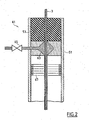
- the application of the insulating material on the smooth cable 3 can be performed during drawing or conditioning of the cable 3. This application can also be carried out on the site, in the vicinity of the cavity 13, by means of a device 61 of FIG. described application Figure 2 .
- This application device can be inserted in the lock 51 between its end 53 and the intervention valve 33 of the wellhead. It comprises a chamber 63 for applying an insulating product injected through a valve 65 and means 67 for cooking, melting or polymerizing this product, such as, for example, induction heating coils.
- the return pulleys 49 and the winder 42 must be electrically isolated from the wellhead and / or the formation 19 to ensure the proper functioning of the transmission device. according to the invention.
- the application device 61 can also be placed between the winch 41 and the lower idler pulley 49.
- an uncoated standard smooth cable 3 (whose diameter is for example 2.34 mm or 2.74 mm) and to apply to this smooth cable 3 a coating of thickness equal to half the difference in diameter. between this cable 3 and a standard smooth cable of greater diameter.
- the diameter of the coated smooth cable 3 is of standard size compared to the existing equipment of "slick line" (2.74 mm or 3.17 mm in the example above). The coated smooth cable 3 then easily adapts to existing "slick line" equipment.
- the smooth cable 3 can be electrically isolated from the second conduit by means of centralizers 71 of insulating material arranged at regular intervals in the second conduit 25, without the use of an insulating coating.
- First means 9 for transmitting and receiving an electrical signal are arranged in the vicinity of the wellhead 15. They comprise a control unit 73, electrically connected on the one hand to the smooth cable 3 and on the other hand to the wellhead 15.
- Second means 11 for transmitting and receiving an electrical signal are mounted on the second end of the smooth cable 3 in the vicinity of the tool 55.
- the second transmitting and receiving means 11 are connected to the control part. 57.
- these means 11 are also electrically connected on the one hand to the smooth cable 3 and on the other hand to the second conduit 25.
- the first and second transmission and reception means comprise an electronic circuit and an energy source, for example a battery. They can send and receive a modulated alternating electric signal of low or medium frequency. These means known per se are not described in detail.
- An example of a transmitter / receiver that can be used in this device is provided by GEOSERVICES under the name WTD (Wireless Transmitted Data).
- Low or medium frequency means frequencies between 1 Hz and 50000 Hz, preferably between 5 Hz and 5000 Hz.
- the transmission of data between the transmitting means and the receiving means takes place over distances between 0 and 10000 m, preferably between 500 and 6000 m.
- the electrical signal transmitted from the surface to the bottom is, in this case, a control signal generated by the operator and the electrical signal transmitted from the bottom to the surface is a validation signal generated by the control part 57.
- the current injected by the emitting means 9, 11 is between 0 and 10 amperes, preferably between 0 and 2 amps, at a voltage of 0 to 50 volts, preferably 5 to 25 volts.
- These means are identical to those commonly used in the context of electromagnetic signal data transmission.
- a current source as used in torronized electric cable signal transmissions may be used in this first embodiment.
- An example of a current source that can be used is provided by the company GEOSERVICES under the name EMROD ® shuttle.
- the surface operator actuates a simple transmitter 9 and the intervention unit 5 and / or measurements may be provided only with receiving means 11.
- intervention and / or measurement assembly 5 may also comprise means (not shown) for detecting physical quantities such as temperature, pressure, flow, depth, status of a depth valve, radiation natural terrain ( ⁇ radiation), localization of Casing Collar Locators or other.
- the intervention and / or measurement assembly may comprise only detection means and a transmitter 11, the surface then being equipped only with reception means 9.
- the first transmission / reception means 9 on the ground surface 17 emit an electrical control signal in the form of a modulated electric current. Since the smooth cable 3 is electrically isolated from the second conduit 25, a current loop is established between the first transmission / reception means 9, the smooth cable 3, the second transmission / reception means 11, the second conduit 25 and the wellhead 15. Despite the poor electrical conductivity properties of the cable 3, the electrical control signal is transmitted to the control member 57 of the intervention and / or measurement assembly via the cable 3. active part 55 of the intervention set 5 and / or measurements then executes the command for example, trigger an explosive charge.
- the second transmission / reception means 11 emit an electrical validation signal in the form of an electric current flowing on the current loop described previously.
- This validation signal is received by the first transmitting / receiving means 9.
- a surface operator can therefore receive a confirmation of the proper execution of the commanded operation and proceed to the next operation (for example, reassembling the cable and the intervention set and / or measures).
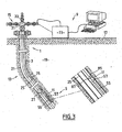
- a second data transmission device is represented on the Figure 3 .
- the smooth cable 3 is disposed in the annular space between the first conduit 21 and the second conduit 25.
- This smooth cable 3 is permanently installed in the oil well installation represented Figure 3 .
- the smooth cable 3 can be fixed on the outer surface of the second conduit 25 by fasteners 75 and positioned during the introduction of the second conduit 25 in the first conduit 21.
- the outer surface of the smooth cable 3 is coated with a permanently applied insulating material.
- the deployment means 7 are no longer necessary.
- the smooth cable is therefore directly connected to the control unit 73.
- the operation of the second device according to the invention is also identical to that of the first device according to the invention.
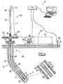
- a third data transmission device is represented on the Figure 4 .
- the surface of the smooth cable 3 has at least one electrical contact point 81 with the second conduit 25.
- the first transmitting / receiving means 9 are electrically connected on the one hand to the smooth cable 3 and on the other hand to the formation of the sub-ground 19, via a pile 83 made of a conductive material. electricity, planted in formation 19 on the soil surface 17.
- the pile 83 can be planted in an underwater bottom, if the installation is related to drilling in the open sea.
- the operation of the third device according to the invention is similar to that of the first device according to the invention.
- the first transmission / reception means 9 emit an electrical control signal. This signal is identical to that generated in the first device according to the invention. It can therefore be generated by identical means.
- This signal is injected into a first dipole formed by, on the one hand, the point of contact 84 between the cable 3 and the first transmission / reception means and, on the other hand, the pile 83.
- the electric signal injected into this first dipole gives rise to the propagation, in the terrain surrounding the well of an electromagnetic control signal, in this case an electromagnetic wave, which contains the information to be transmitted.
- This electromagnetic control signal then descends towards the bottom of the well, guided by the smooth cable 3 and / or the second conduit 25.
- This electromagnetic control signal is collected by a second dipole formed between, on the one hand, the contact point 81 of the cable 3 with the second conduit 25 closest to the intervention and / or measurement assembly 5 and, secondly, the electrical contact point 87 of the second transmission / reception means 9 with the second conduit 25, the second conduit being electrically connected to the formation 19 by the centralizers 27 and the first conduit 21.
- the electromagnetic signal received on the second dipole generates an electrical signal which is received by the second transmitting / receiving means 11.
- the validation signal of the intervention and / or measurement assembly 5 is generated in the form of an electrical signal injected on a first dipole formed by, on the one hand, the electrical contact point 81 between the 3 and the second conduit 25 closest to the intervention 5 and / or measurements assembly and, on the other hand, the electrical contact point 87 between the transmission means 11 and the second conduit 25. last contact point is electrically connected to the formation 19.
- the electrical signal injected into the first dipole gives rise to the propagation, in the terrain surrounding the well of an electromagnetic control signal, in this case an electromagnetic wave, which contains the information to be transmitted.
- This electromagnetic validation signal then rises to the surface, guided by the smooth cable 3 and / or the second conduit 25.
- This electromagnetic validation signal is collected by a second dipole formed between, on the one hand, the electrical contact point 84 first transmission / reception means 9 with the cable 3 and, on the other hand, the electrical contact point of the first transmission / reception means 9 with the formation 19 at the pile 83.
- the electromagnetic signal received on the second dipole generates an electrical signal which is received by the first transmitting / receiving means 9.
- a device for the transmission of real-time data between a tool located at the end of a smooth single-strand cable of the "piano wire" type arranged in the bottom of the an installation of oil production wells and a control device on the surface.
- the device can easily adapt to an existing installation.
Claims (16)
- Datenübertragungsvorrichtung für eine Anlage (1) zur Gewinnung von Fluiden, die in Untergrund (19) enthalten sind, wobei die Anlage einen Hohlraum (13) umfasst, der in einer Formation des Untergrunds (19) ausgehend von der Bodenoberfläche (17) begrenzt ist, wobei dieser Hohlraum (13) mit wenigstens einem Elektrizität leitenden rohrförmigen Element (21; 25) versehen ist, wobei diese Vorrichtung von dem Typ ist, der ein glattes einsträngiges Kabel (3) zum Tragen einer Anordnung (5) für den Eingriff und/oder für Messungen umfasst, das aus einem Elektrizität leitenden Material verwirklicht ist, wobei das Kabel in dem rohrförmigen Element (21; 25) zwischen einem ersten Punkt auf der Bodenoberfläche (17) und einem zweiten Punkt im Hohlraum (13) angeordnet ist, wobei die Oberfläche des Kabels (3) wenigstens teilweise von dem rohrförmigen Element (21; 25) elektrisch isoliert ist, wobei die Vorrichtung außerdem Mittel (9, 11) zum Aussenden eines elektrischen und/oder elektromagnetischen Signals, die sich in der Nähe des ersten und/oder des zweiten Punkts befinden, und Mittel (9, 11) zum Empfangen eines elektrischen und/oder elektromagnetischen Signals, die sich in der Nähe des anderen des ersten und/oder des zweiten Punkts befinden, umfasst; dadurch gekennzeichnet, dass das Kabel eine Bruchlast größer als 300 daN aufweist und dass jedes der Sendemittel und jedes der Empfangsmittel einerseits mit dem Kabel (3) und andererseits mit dem rohrförmigen Element (21; 25) und/oder mit der Formation (19) elektrisch verbunden ist; wobei das Kabel (3) einen Teil der Übertragungsschleife des elektrischen und/oder elektromagnetischen Signals zwischen den Sendemitteln (9, 11) und den Empfangsmitteln (9, 11) bildet.
- Übertragungsvorrichtung nach Anspruch 1, dadurch gekennzeichnet, dass die Oberfläche des Kabels (3) eine ununterbrochene Beschichtung aus einem Isoliermaterial aufweist und gegenüber dem rohrförmigen Element (21; 25) elektrisch isoliert ist.
- Übertragungsvorrichtung nach Anspruch 2, dadurch gekennzeichnet, dass die Dicke der ununterbrochenen Beschichtung aus Isoliermaterial gleich der halben Durchmesserdifferenz zwischen zwei nicht beschichteten Standardkabeln (3) ist.
- Übertragungsvorrichtung nach Anspruch 1, dadurch gekennzeichnet, dass die Oberfläche des Kabels (3) in regelmäßigen Intervallen mit Zentrierelementen (71) aus Isoliermaterial versehen ist, um sie gegenüber dem rohrförmigen Element (21; 25) elektrisch zu isolieren.
- Übertragungsvorrichtung nach einem der Ansprüche 1 bis 4, dadurch gekennzeichnet, dass die Sende- und Empfangsmittel (9, 11) in der Umgebung des ersten und des zweiten Punkts mit dem rohrförmigen Element (21; 25) elektrisch verbunden sind und dass das von den Sendemitteln (9, 11) ausgesendete und von den Empfangsmitteln (9, 11) empfangene Signal ein elektrisches Signal ist.
- Übertragungsvorrichtung nach einem der Ansprüche 1 bis 5, dadurch gekennzeichnet, dass der Hohlraum (13) mit wenigstens einem ersten rohrförmigen Element (21) und einem zweiten rohrförmigen Element (25), das innerhalb des ersten Elements (21) angeordnet ist, versehen ist und dass das Kabel (3) in dem ringförmigen Raum zwischen dem ersten Element (21) und dem zweiten Element (25) angeordnet ist.
- Übertragungsvorrichtung nach einem der Ansprüche 1 bis 4, dadurch gekennzeichnet, dass die Oberfläche des Kabels (3) wenigstens einen Punkt (81) für elektrischen Kontakt mit dem rohrförmigen Element (21; 25) besitzt und dass die Sende- und/oder Empfangsmittel (9, 11) in der Umgebung des ersten und des zweiten Punkts und das rohrförmige Element (21; 25) mit der Formation (19) elektrisch verbunden sind.
- Übertragungsvorrichtung nach Anspruch 7, dadurch gekennzeichnet, dass das von den Sendemitteln (9) in der Umgebung des ersten Punkts ausgesendete elektrische Signal in einen ersten Dipol eingeleitet wird, der einerseits einen Punkt (84) für elektrischen Kontakt zwischen den Sendemitteln (9) in der Umgebung des ersten Punkts und dem Kabel (3) und andererseits einen Punkt (83) für elektrischen Kontakt zwischen den Sendemitteln (9) in der Umgebung des ersten Punkts und der Formation (19) aufweist; wobei dieser erste Dipol ein elektromagnetisches Signal erzeugt, das von einem zweiten Dipol empfangen wird, der einerseits einen der Punkte (81) für elektrischen Kontakt zwischen dem Kabel (3) und dem rohrförmigen Element (21; 25) und andererseits einen Punkt (87) für elektrischen Kontakt zwischen den Empfangsmitteln (11) in der Umgebung des zweiten Punkts und dem rohrförmigen Element (21; 25) aufweist, wobei das von dem zweiten Dipol empfangene elektromagnetische Signal ein elektrisches Signal erzeugt, das zu den Empfangsmitteln (11) in der Umgebung des zweiten Punkts übertragen wird.
- Übertragungsvorrichtung nach einem der Ansprüche 7 oder 8, dadurch gekennzeichnet, dass das elektrische Signal, das von den Sendemitteln (11) in der Umgebung des zweiten Punkts ausgesendet wird, in einen zweiten Dipol eingeleitet wird, der einerseits einen der Punkte (81) für elektrischen Kontakt zwischen dem Kabel und dem rohrförmigen Element (21; 25) und andererseits einen Punkt (87) für elektrischen Kontakt zwischen den Sendemitteln (11) in der Umgebung des zweiten Punkts und dem rohrförmigen Element (21; 25) aufweist; wobei dieser zweite Dipol ein elektromagnetisches Signal erzeugt, das von einem ersten Dipol empfangen wird, der einerseits einen Punkt (84) für elektrischen Kontakt zwischen den Empfangsmitteln (9) in der Umgebung des ersten Punkts und dem Kabel (3) und andererseits einen Punkt (83) für elektrischen Kontakt zwischen den Empfangsmitteln (9) in der Umgebung des ersten Punkts und der Formation (19) aufweist; wobei das elektromagnetische Signal, das von dem ersten Dipol empfangen wird, ein elektrisches Signal erzeugt, das zu den Empfangsmitteln (9) in der Umgebung des ersten Punkts übertragen wird.
- Übertragungsvorrichtung nach einem der Ansprüche 7 bis 9, dadurch gekennzeichnet, dass der elektrische Kontakt zwischen den Sendemitteln und/oder Empfangsmitteln in der Umgebung des ersten Punkts und der Formation mittels eines Leiterorgans (83), das im Boden (19) verankert ist, erfolgt.
- Übertragungsvorrichtung nach einem der Ansprüche 1 bis 10, dadurch gekennzeichnet, dass sich Sendemittel (9, 11) und Empfangsmittel (9, 11) für ein elektrisches und/oder elektromagnetisches Signal in der Umgebung des einen und des anderen des ersten und des zweiten Punkts befinden.
- Übertragungsvorrichtung nach einem der Ansprüche 1 bis 10, dadurch gekennzeichnet, dass sich Sendemittel (9) für ein elektrisches und/oder elektromagnetisches Signal ausschließlich in der Umgebung eines des ersten und des zweiten Punkts befinden und sich die Empfangsmittel (11) für ein elektrisches und/oder elektromagnetisches Signal ausschließlich in der Umgebung des anderen des ersten und des zweiten Punkts befinden.
- Anlage zur Gewinnung von in einem Untergrund (19) enthaltenen Fluiden, wobei die Anlage einen Hohlraum (13) umfasst, der in einer Formation des Untergrunds (19) ausgehend von der Oberfläche (17) des Bodens begrenzt ist und auf Höhe des Bodens durch einen Bohrlochkopf (15) verschlossen ist, wobei dieser Hohlraum (13) mit wenigstens einem Elektrizität leitenden rohrförmigen Element (21; 25) versehen ist, dadurch gekennzeichnet, dass sie eine Übertragungsvorrichtung nach einem der Ansprüche 1 bis 12 umfasst.
- Anlage nach Anspruch 13, dadurch gekennzeichnet, dass sie eine Vorrichtung (61) für die Aufbringung einer Isolierbeschichtung auf das Kabel (3) umfasst.
- Anlage nach Anspruch 14, wobei dem Bohrlochkopf (15) eine Schleusenkammer (51) vorhergeht, die mit einer Dichtungsvorrichtung (53) für das Kabel (3) versehen ist, dadurch gekennzeichnet, dass die Vorrichtung (61) für die Aufbringung der Isolierbeschichtung auf das Kabel (3) in der Schleusenkammer (51) stromabseitig der Dichtungsvorrichtung (53) angeordnet ist.
- Anlage nach Anspruch 14, die Ausfahrmittel (7) und eine Ausrichtvorrichtung (43) für das Kabel (3) im Bohrlochkopf (15) umfasst, die wenigstens eine Riemenscheibe (49) aufweisen, dadurch gekennzeichnet, dass die Vorrichtung (61) für die Aufbringung der Isolierbeschichtung auf das Kabel (3) zwischen den Ausfahrmitteln (7) und der Ausrichtvorrichtung (43) angeordnet ist und dass die oder jede Riemenscheibe (49) gegenüber dem Bohrlochkopf (15) und/oder der Formation (19) elektrisch isoliert ist.
Applications Claiming Priority (3)
| Application Number | Priority Date | Filing Date | Title |
|---|---|---|---|
| FR0215608A FR2848363B1 (fr) | 2002-12-10 | 2002-12-10 | Dispositif de transmission de donnees pour une installation d'exploitation de fluides contenus dans un sous-sol. |
| FR0215608 | 2002-12-10 | ||
| PCT/FR2003/003526 WO2004063528A1 (fr) | 2002-12-10 | 2003-11-28 | Dispositif de transmission de donnees |
Publications (2)
| Publication Number | Publication Date |
|---|---|
| EP1570157A1 EP1570157A1 (de) | 2005-09-07 |
| EP1570157B1 true EP1570157B1 (de) | 2015-08-12 |
Family
ID=32320168
Family Applications (1)
| Application Number | Title | Priority Date | Filing Date |
|---|---|---|---|
| EP03789526.5A Expired - Lifetime EP1570157B1 (de) | 2002-12-10 | 2003-11-28 | Vorrichtung zur datenübertragung |
Country Status (12)
| Country | Link |
|---|---|
| US (1) | US7652592B2 (de) |
| EP (1) | EP1570157B1 (de) |
| JP (1) | JP3984995B2 (de) |
| KR (1) | KR100721165B1 (de) |
| CN (1) | CN100393980C (de) |
| AU (1) | AU2003294106B2 (de) |
| BR (1) | BR0316582A (de) |
| DK (1) | DK1570157T3 (de) |
| FR (1) | FR2848363B1 (de) |
| MX (1) | MXPA05006037A (de) |
| NZ (1) | NZ540635A (de) |
| WO (1) | WO2004063528A1 (de) |
Families Citing this family (21)
| Publication number | Priority date | Publication date | Assignee | Title |
|---|---|---|---|---|
| GB0505855D0 (en) * | 2005-03-22 | 2005-04-27 | Expro North Sea Ltd | Signalling downhole |
| US8305227B2 (en) * | 2005-06-15 | 2012-11-06 | Wfs Technologies Ltd. | Wireless auxiliary monitoring and control system for an underwater installation |
| WO2009048459A1 (en) | 2007-10-09 | 2009-04-16 | Halliburton Energy Services | Telemetry system for slickline enabling real time logging |
| FR2946998A1 (fr) | 2009-06-17 | 2010-12-24 | Geoservices Equipements | Outil intermediaire de deconnexion destine a etre place dans une navette descendue dans un puits d'exploitation de fluide, navette et procede associes. |
| BR112012027569A2 (pt) | 2010-04-27 | 2019-09-24 | Geoservices Equipements | caixa de enchimento para um poço de produção de fluido, e conjunto de superfície para um poço de produção de fluido. |
| EP2469014A1 (de) | 2010-12-21 | 2012-06-27 | Geoservices Equipements | Werkzeug zum Extrahieren eines in einem Flüssigkeitsausnutzungsrohr festsitzenden Objekts, Extraktionsvorrichtung und zugehöriges Verfahren |
| EA027088B1 (ru) | 2011-12-28 | 2017-06-30 | Пэредайм Текнолоджи Сёрвисиз Б.В. | Система связи для скважины |
| US9091153B2 (en) | 2011-12-29 | 2015-07-28 | Schlumberger Technology Corporation | Wireless two-way communication for downhole tools |
| EP2650662B1 (de) | 2012-04-10 | 2015-05-27 | Geoservices Equipements | Spannungsmesser zum Messen einer mechanischen Spannung in Längsrichtung in einem Bohrloch und zugehörige Unteranordnung und Verfahren |
| JP2015520313A (ja) * | 2012-06-22 | 2015-07-16 | ノーチラス・ミネラルズ・パシフイツク・プロプライエタリー・リミテツド | 海中掘削作業においてダウンホールツールを作動する装置、システム及び方法 |
| US9863237B2 (en) * | 2012-11-26 | 2018-01-09 | Baker Hughes, A Ge Company, Llc | Electromagnetic telemetry apparatus and methods for use in wellbore applications |
| US9964660B2 (en) | 2013-07-15 | 2018-05-08 | Baker Hughes, A Ge Company, Llc | Electromagnetic telemetry apparatus and methods for use in wellbores |
| GB2530947B (en) | 2013-09-27 | 2017-03-01 | Paradigm Tech Services B V | A tool and method for use within an elongated space |
| EP3190433B1 (de) | 2014-08-03 | 2021-11-03 | Services Pétroliers Schlumberger | Installation mit einem Neutronengenerator zur Intervention in einem Bohrloch und damit zusammenhängendes Verfahren |
| GB201500884D0 (en) | 2015-01-19 | 2015-03-04 | Paradigm Technology Services B V | Composite slickline communication |
| EP3098613A1 (de) * | 2015-05-28 | 2016-11-30 | Services Pétroliers Schlumberger | System und verfahren zur überwachung der leistungen eines kabels, welches eine bohrlochanordnung trägt |
| EP3135619A1 (de) | 2015-08-25 | 2017-03-01 | Services Pétroliers Schlumberger | Hülse zur montage um eine aufspultrommel |
| US10738589B2 (en) | 2016-05-23 | 2020-08-11 | Schlumberger Technology Corporation | System and method for monitoring the performances of a cable carrying a downhole assembly |
| GB201713209D0 (en) * | 2017-08-17 | 2017-10-04 | Ziebel As | Well logging assembly |
| WO2020081073A1 (en) * | 2018-10-17 | 2020-04-23 | Halliburton Energy Services, Inc. | Slickline selective perforating system |
| WO2020149858A1 (en) * | 2019-01-18 | 2020-07-23 | Halliburton Energy Services, Inc. | Electromagnetic telemetry using non-polarizing electrodes |
Citations (11)
| Publication number | Priority date | Publication date | Assignee | Title |
|---|---|---|---|---|
| US3187301A (en) * | 1959-06-05 | 1965-06-01 | Pgac Dev Company | Telemetering system for use in borehole logging to control downhole tool from surface |
| US3453530A (en) * | 1968-03-01 | 1969-07-01 | Schlumberger Technology Corp | Methods and apparatus for investigating earth formations including measuring the resistivity of radially different formation zones |
| GB2101178A (en) * | 1981-05-13 | 1983-01-12 | Otis Eng Co | Control valve |
| US4532614A (en) * | 1981-06-01 | 1985-07-30 | Peppers James M | Wall bore electrical generator |
| US4876539A (en) * | 1983-08-15 | 1989-10-24 | Oil Dynamics, Inc. | Parameter telemetering from the bottom of a deep borehole |
| US5048603A (en) * | 1990-05-29 | 1991-09-17 | Bell Larry M | Lubricator corrosion inhibitor treatment |
| WO1995004290A1 (en) * | 1993-08-02 | 1995-02-09 | Moore Boyd B | Improved slick line system with real-time surface display |
| US5394141A (en) * | 1991-09-12 | 1995-02-28 | Geoservices | Method and apparatus for transmitting information between equipment at the bottom of a drilling or production operation and the surface |
| EP0773345A1 (de) * | 1995-11-07 | 1997-05-14 | Schlumberger Technology B.V. | Verfahren und Vorrichtung zur akustischen Übertragung von die im Bohrlochgespeicherten Messdaten |
| WO2001086831A1 (en) * | 2000-05-05 | 2001-11-15 | Baker Hughes Incorporated | Method for multi-phase data communications and control over an esp power cable |
| US6392561B1 (en) * | 1998-12-18 | 2002-05-21 | Dresser Industries, Inc. | Short hop telemetry system and method |
Family Cites Families (6)
| Publication number | Priority date | Publication date | Assignee | Title |
|---|---|---|---|---|
| FR2613159B1 (fr) * | 1987-03-27 | 1989-07-21 | Inst Francais Du Petrole | Systeme de transmission de signaux entre un ensemble de reception descendu dans un puits et un laboratoire central de commande et d'enregistrement |
| US5233297A (en) * | 1990-08-06 | 1993-08-03 | Atlantic Richfield Company | Transient electromagnetic method and apparatus for inspecting conductive objects utilizing sensors that move during inspection |
| US5974159A (en) * | 1996-03-29 | 1999-10-26 | Sarnoff Corporation | Method and apparatus for assessing the visibility of differences between two image sequences |
| US5694491A (en) * | 1996-03-29 | 1997-12-02 | David Sarnoff Research Center, Inc. | Methods and apparatus for assessing the visibility of differences between two image sequences |
| US5719966A (en) * | 1996-03-29 | 1998-02-17 | David Sarnoff Research Center, Inc. | Apparatus for assessing the visiblity of differences between two image sequences |
| GB9921554D0 (en) * | 1999-09-14 | 1999-11-17 | Mach Limited | Apparatus and methods relating to downhole operations |
-
2002
- 2002-12-10 FR FR0215608A patent/FR2848363B1/fr not_active Expired - Fee Related
-
2003
- 2003-11-28 CN CNB2003801084201A patent/CN100393980C/zh not_active Expired - Lifetime
- 2003-11-28 KR KR1020057010479A patent/KR100721165B1/ko not_active IP Right Cessation
- 2003-11-28 WO PCT/FR2003/003526 patent/WO2004063528A1/fr active Application Filing
- 2003-11-28 EP EP03789526.5A patent/EP1570157B1/de not_active Expired - Lifetime
- 2003-11-28 JP JP2004566082A patent/JP3984995B2/ja not_active Expired - Fee Related
- 2003-11-28 NZ NZ540635A patent/NZ540635A/en not_active IP Right Cessation
- 2003-11-28 US US10/538,503 patent/US7652592B2/en active Active
- 2003-11-28 BR BR0316582-5A patent/BR0316582A/pt not_active IP Right Cessation
- 2003-11-28 MX MXPA05006037A patent/MXPA05006037A/es active IP Right Grant
- 2003-11-28 AU AU2003294106A patent/AU2003294106B2/en not_active Expired
- 2003-11-28 DK DK03789526.5T patent/DK1570157T3/en active
Patent Citations (11)
| Publication number | Priority date | Publication date | Assignee | Title |
|---|---|---|---|---|
| US3187301A (en) * | 1959-06-05 | 1965-06-01 | Pgac Dev Company | Telemetering system for use in borehole logging to control downhole tool from surface |
| US3453530A (en) * | 1968-03-01 | 1969-07-01 | Schlumberger Technology Corp | Methods and apparatus for investigating earth formations including measuring the resistivity of radially different formation zones |
| GB2101178A (en) * | 1981-05-13 | 1983-01-12 | Otis Eng Co | Control valve |
| US4532614A (en) * | 1981-06-01 | 1985-07-30 | Peppers James M | Wall bore electrical generator |
| US4876539A (en) * | 1983-08-15 | 1989-10-24 | Oil Dynamics, Inc. | Parameter telemetering from the bottom of a deep borehole |
| US5048603A (en) * | 1990-05-29 | 1991-09-17 | Bell Larry M | Lubricator corrosion inhibitor treatment |
| US5394141A (en) * | 1991-09-12 | 1995-02-28 | Geoservices | Method and apparatus for transmitting information between equipment at the bottom of a drilling or production operation and the surface |
| WO1995004290A1 (en) * | 1993-08-02 | 1995-02-09 | Moore Boyd B | Improved slick line system with real-time surface display |
| EP0773345A1 (de) * | 1995-11-07 | 1997-05-14 | Schlumberger Technology B.V. | Verfahren und Vorrichtung zur akustischen Übertragung von die im Bohrlochgespeicherten Messdaten |
| US6392561B1 (en) * | 1998-12-18 | 2002-05-21 | Dresser Industries, Inc. | Short hop telemetry system and method |
| WO2001086831A1 (en) * | 2000-05-05 | 2001-11-15 | Baker Hughes Incorporated | Method for multi-phase data communications and control over an esp power cable |
Also Published As
| Publication number | Publication date |
|---|---|
| AU2003294106B2 (en) | 2009-03-12 |
| CN100393980C (zh) | 2008-06-11 |
| JP2006509941A (ja) | 2006-03-23 |
| DK1570157T3 (en) | 2015-11-30 |
| KR20050105976A (ko) | 2005-11-08 |
| FR2848363B1 (fr) | 2005-03-11 |
| KR100721165B1 (ko) | 2007-05-25 |
| NZ540635A (en) | 2006-11-30 |
| WO2004063528A1 (fr) | 2004-07-29 |
| EP1570157A1 (de) | 2005-09-07 |
| FR2848363A1 (fr) | 2004-06-11 |
| CN1735741A (zh) | 2006-02-15 |
| MXPA05006037A (es) | 2005-08-18 |
| US20060044155A1 (en) | 2006-03-02 |
| US7652592B2 (en) | 2010-01-26 |
| AU2003294106A1 (en) | 2004-08-10 |
| BR0316582A (pt) | 2005-10-04 |
| JP3984995B2 (ja) | 2007-10-03 |
Similar Documents
| Publication | Publication Date | Title |
|---|---|---|
| EP1570157B1 (de) | Vorrichtung zur datenübertragung | |
| FR2883915B1 (fr) | Methode et conduit pour transmettre des signaux, en particulier dans un puits de forage | |
| CA2701177C (en) | Telemetry system for slickline enabling real time logging | |
| CA2286435C (fr) | Methode et systeme de transmission d'informations par onde electromagnetique | |
| CA2019421C (fr) | Methode et dispositif pour conduire des operations de perforation dans un puits | |
| EP1501999B1 (de) | Meeresboden/flächen-verbindungsinstallation für eine unterwasserrohrleitung, die durch mindestens ein durch eine basis gestütztes rohrkniestück mit einem steigrohr verbunden ist | |
| FR2697119A1 (fr) | Dispositif émetteur à double raccord isolant, destiné à l'emploi dans un forage. | |
| FR2750450A1 (fr) | Dispositif et methode de transmission d'informations par onde electromagnetique | |
| EP2312116A2 (de) | Gehäusehänger-Verschachtelungsanzeige | |
| FR2501777A1 (fr) | Methode et dispositif pour effectuer, a l'aide d'outils specialises, des operations telles que des mesures, dans des portions de puits fortement inclinees sur la verticale, ou horizontales | |
| US9441431B2 (en) | Intervention device for use in a fluid exploitation well in the subsoil, and associated intervention assembly | |
| WO2016001546A1 (fr) | Dispositif et procédé de mise en place d'un manchon tubulaire de jonction pour conduite comportant un chemisage interne | |
| EP1473256B1 (de) | Verfahren und Vorrichtung zur Datenübertragung zwischen Übertage und einem untertägigen Salzhohlraum | |
| AU2012257724B2 (en) | Method and system for protecting a conduit in an annular space around a well casing | |
| CA2527364C (en) | Downhole communication | |
| WO2006008361A1 (fr) | Train de tiges apte a la transmission d'informations a haut debit dans un puits de forage | |
| FR2570818A1 (fr) | Procede et appareil de transmission de signaux electriques et electro-optiques pour telemetrie | |
| FR2962154A1 (fr) | Mesure de donnees sur les parois exterieures d'un tubage de forage | |
| FR2988769A1 (fr) | Dispositif de colmatage de puits |
Legal Events
| Date | Code | Title | Description |
|---|---|---|---|
| PUAI | Public reference made under article 153(3) epc to a published international application that has entered the european phase |
Free format text: ORIGINAL CODE: 0009012 |
|
| 17P | Request for examination filed |
Effective date: 20050606 |
|
| AK | Designated contracting states |
Kind code of ref document: A1 Designated state(s): AT BE BG CH CY CZ DE DK EE ES FI FR GB GR HU IE IT LI LU MC NL PT RO SE SI SK TR |
|
| AX | Request for extension of the european patent |
Extension state: AL LT LV MK |
|
| DAX | Request for extension of the european patent (deleted) | ||
| RAP1 | Party data changed (applicant data changed or rights of an application transferred) |
Owner name: GEOSERVICES EQUIPEMENTS |
|
| 17Q | First examination report despatched |
Effective date: 20100421 |
|
| GRAP | Despatch of communication of intention to grant a patent |
Free format text: ORIGINAL CODE: EPIDOSNIGR1 |
|
| INTG | Intention to grant announced |
Effective date: 20141105 |
|
| GRAS | Grant fee paid |
Free format text: ORIGINAL CODE: EPIDOSNIGR3 |
|
| GRAP | Despatch of communication of intention to grant a patent |
Free format text: ORIGINAL CODE: EPIDOSNIGR1 |
|
| INTG | Intention to grant announced |
Effective date: 20150330 |
|
| GRAF | Information related to payment of grant fee modified |
Free format text: ORIGINAL CODE: EPIDOSCIGR3 |
|
| GRAA | (expected) grant |
Free format text: ORIGINAL CODE: 0009210 |
|
| AK | Designated contracting states |
Kind code of ref document: B1 Designated state(s): AT BE BG CH CY CZ DE DK EE ES FI FR GB GR HU IE IT LI LU MC NL PT RO SE SI SK TR |
|
| REG | Reference to a national code |
Ref country code: GB Ref legal event code: FG4D Free format text: NOT ENGLISH |
|
| REG | Reference to a national code |
Ref country code: CH Ref legal event code: EP |
|
| REG | Reference to a national code |
Ref country code: AT Ref legal event code: REF Ref document number: 742346 Country of ref document: AT Kind code of ref document: T Effective date: 20150815 |
|
| REG | Reference to a national code |
Ref country code: IE Ref legal event code: FG4D Free format text: LANGUAGE OF EP DOCUMENT: FRENCH |
|
| REG | Reference to a national code |
Ref country code: DE Ref legal event code: R096 Ref document number: 60347921 Country of ref document: DE |
|
| REG | Reference to a national code |
Ref country code: DK Ref legal event code: T3 Effective date: 20151124 |
|
| REG | Reference to a national code |
Ref country code: AT Ref legal event code: MK05 Ref document number: 742346 Country of ref document: AT Kind code of ref document: T Effective date: 20150812 |
|
| REG | Reference to a national code |
Ref country code: NL Ref legal event code: FP |
|
| PG25 | Lapsed in a contracting state [announced via postgrant information from national office to epo] |
Ref country code: FI Free format text: LAPSE BECAUSE OF FAILURE TO SUBMIT A TRANSLATION OF THE DESCRIPTION OR TO PAY THE FEE WITHIN THE PRESCRIBED TIME-LIMIT Effective date: 20150812 Ref country code: GR Free format text: LAPSE BECAUSE OF FAILURE TO SUBMIT A TRANSLATION OF THE DESCRIPTION OR TO PAY THE FEE WITHIN THE PRESCRIBED TIME-LIMIT Effective date: 20151113 |
|
| REG | Reference to a national code |
Ref country code: RO Ref legal event code: EPE |
|
| PG25 | Lapsed in a contracting state [announced via postgrant information from national office to epo] |
Ref country code: AT Free format text: LAPSE BECAUSE OF FAILURE TO SUBMIT A TRANSLATION OF THE DESCRIPTION OR TO PAY THE FEE WITHIN THE PRESCRIBED TIME-LIMIT Effective date: 20150812 Ref country code: ES Free format text: LAPSE BECAUSE OF FAILURE TO SUBMIT A TRANSLATION OF THE DESCRIPTION OR TO PAY THE FEE WITHIN THE PRESCRIBED TIME-LIMIT Effective date: 20150812 Ref country code: PT Free format text: LAPSE BECAUSE OF FAILURE TO SUBMIT A TRANSLATION OF THE DESCRIPTION OR TO PAY THE FEE WITHIN THE PRESCRIBED TIME-LIMIT Effective date: 20151214 Ref country code: SE Free format text: LAPSE BECAUSE OF FAILURE TO SUBMIT A TRANSLATION OF THE DESCRIPTION OR TO PAY THE FEE WITHIN THE PRESCRIBED TIME-LIMIT Effective date: 20150812 |
|
| PG25 | Lapsed in a contracting state [announced via postgrant information from national office to epo] |
Ref country code: CZ Free format text: LAPSE BECAUSE OF FAILURE TO SUBMIT A TRANSLATION OF THE DESCRIPTION OR TO PAY THE FEE WITHIN THE PRESCRIBED TIME-LIMIT Effective date: 20150812 Ref country code: SK Free format text: LAPSE BECAUSE OF FAILURE TO SUBMIT A TRANSLATION OF THE DESCRIPTION OR TO PAY THE FEE WITHIN THE PRESCRIBED TIME-LIMIT Effective date: 20150812 Ref country code: EE Free format text: LAPSE BECAUSE OF FAILURE TO SUBMIT A TRANSLATION OF THE DESCRIPTION OR TO PAY THE FEE WITHIN THE PRESCRIBED TIME-LIMIT Effective date: 20150812 |
|
| REG | Reference to a national code |
Ref country code: DE Ref legal event code: R097 Ref document number: 60347921 Country of ref document: DE |
|
| PLBE | No opposition filed within time limit |
Free format text: ORIGINAL CODE: 0009261 |
|
| STAA | Information on the status of an ep patent application or granted ep patent |
Free format text: STATUS: NO OPPOSITION FILED WITHIN TIME LIMIT |
|
| PG25 | Lapsed in a contracting state [announced via postgrant information from national office to epo] |
Ref country code: LU Free format text: LAPSE BECAUSE OF FAILURE TO SUBMIT A TRANSLATION OF THE DESCRIPTION OR TO PAY THE FEE WITHIN THE PRESCRIBED TIME-LIMIT Effective date: 20151128 Ref country code: MC Free format text: LAPSE BECAUSE OF FAILURE TO SUBMIT A TRANSLATION OF THE DESCRIPTION OR TO PAY THE FEE WITHIN THE PRESCRIBED TIME-LIMIT Effective date: 20150812 |
|
| REG | Reference to a national code |
Ref country code: CH Ref legal event code: PL |
|
| 26N | No opposition filed |
Effective date: 20160513 |
|
| PG25 | Lapsed in a contracting state [announced via postgrant information from national office to epo] |
Ref country code: CH Free format text: LAPSE BECAUSE OF NON-PAYMENT OF DUE FEES Effective date: 20151130 Ref country code: LI Free format text: LAPSE BECAUSE OF NON-PAYMENT OF DUE FEES Effective date: 20151130 |
|
| REG | Reference to a national code |
Ref country code: IE Ref legal event code: MM4A |
|
| REG | Reference to a national code |
Ref country code: FR Ref legal event code: ST Effective date: 20160729 |
|
| PG25 | Lapsed in a contracting state [announced via postgrant information from national office to epo] |
Ref country code: SI Free format text: LAPSE BECAUSE OF FAILURE TO SUBMIT A TRANSLATION OF THE DESCRIPTION OR TO PAY THE FEE WITHIN THE PRESCRIBED TIME-LIMIT Effective date: 20150812 |
|
| PG25 | Lapsed in a contracting state [announced via postgrant information from national office to epo] |
Ref country code: IE Free format text: LAPSE BECAUSE OF NON-PAYMENT OF DUE FEES Effective date: 20151128 |
|
| PG25 | Lapsed in a contracting state [announced via postgrant information from national office to epo] |
Ref country code: FR Free format text: LAPSE BECAUSE OF NON-PAYMENT OF DUE FEES Effective date: 20151130 |
|
| PG25 | Lapsed in a contracting state [announced via postgrant information from national office to epo] |
Ref country code: BG Free format text: LAPSE BECAUSE OF FAILURE TO SUBMIT A TRANSLATION OF THE DESCRIPTION OR TO PAY THE FEE WITHIN THE PRESCRIBED TIME-LIMIT Effective date: 20150812 Ref country code: HU Free format text: LAPSE BECAUSE OF FAILURE TO SUBMIT A TRANSLATION OF THE DESCRIPTION OR TO PAY THE FEE WITHIN THE PRESCRIBED TIME-LIMIT; INVALID AB INITIO Effective date: 20031128 |
|
| PG25 | Lapsed in a contracting state [announced via postgrant information from national office to epo] |
Ref country code: CY Free format text: LAPSE BECAUSE OF FAILURE TO SUBMIT A TRANSLATION OF THE DESCRIPTION OR TO PAY THE FEE WITHIN THE PRESCRIBED TIME-LIMIT Effective date: 20150812 |
|
| PG25 | Lapsed in a contracting state [announced via postgrant information from national office to epo] |
Ref country code: BE Free format text: LAPSE BECAUSE OF NON-PAYMENT OF DUE FEES Effective date: 20151130 |
|
| PG25 | Lapsed in a contracting state [announced via postgrant information from national office to epo] |
Ref country code: TR Free format text: LAPSE BECAUSE OF FAILURE TO SUBMIT A TRANSLATION OF THE DESCRIPTION OR TO PAY THE FEE WITHIN THE PRESCRIBED TIME-LIMIT Effective date: 20150812 |
|
| PGFP | Annual fee paid to national office [announced via postgrant information from national office to epo] |
Ref country code: RO Payment date: 20171122 Year of fee payment: 15 |
|
| PG25 | Lapsed in a contracting state [announced via postgrant information from national office to epo] |
Ref country code: RO Free format text: LAPSE BECAUSE OF NON-PAYMENT OF DUE FEES Effective date: 20181128 |
|
| PGFP | Annual fee paid to national office [announced via postgrant information from national office to epo] |
Ref country code: NL Payment date: 20221019 Year of fee payment: 20 |
|
| PGFP | Annual fee paid to national office [announced via postgrant information from national office to epo] |
Ref country code: IT Payment date: 20221011 Year of fee payment: 20 Ref country code: GB Payment date: 20221006 Year of fee payment: 20 Ref country code: DK Payment date: 20221111 Year of fee payment: 20 Ref country code: DE Payment date: 20221004 Year of fee payment: 20 |
|
| REG | Reference to a national code |
Ref country code: DE Ref legal event code: R071 Ref document number: 60347921 Country of ref document: DE |
|
| REG | Reference to a national code |
Ref country code: NL Ref legal event code: MK Effective date: 20231127 |
|
| REG | Reference to a national code |
Ref country code: DK Ref legal event code: EUP Expiry date: 20231128 |
|
| REG | Reference to a national code |
Ref country code: GB Ref legal event code: PE20 Expiry date: 20231127 |
|
| PG25 | Lapsed in a contracting state [announced via postgrant information from national office to epo] |
Ref country code: GB Free format text: LAPSE BECAUSE OF EXPIRATION OF PROTECTION Effective date: 20231127 |
|
| PG25 | Lapsed in a contracting state [announced via postgrant information from national office to epo] |
Ref country code: GB Free format text: LAPSE BECAUSE OF EXPIRATION OF PROTECTION Effective date: 20231127 |