EP1569854B1 - Behälteranordnungssystem mit mehreren fächern - Google Patents
Behälteranordnungssystem mit mehreren fächern Download PDFInfo
- Publication number
- EP1569854B1 EP1569854B1 EP03772612A EP03772612A EP1569854B1 EP 1569854 B1 EP1569854 B1 EP 1569854B1 EP 03772612 A EP03772612 A EP 03772612A EP 03772612 A EP03772612 A EP 03772612A EP 1569854 B1 EP1569854 B1 EP 1569854B1
- Authority
- EP
- European Patent Office
- Prior art keywords
- sealing
- assembly
- compartment container
- unit
- coupling arms
- Prior art date
- Legal status (The legal status is an assumption and is not a legal conclusion. Google has not performed a legal analysis and makes no representation as to the accuracy of the status listed.)
- Expired - Lifetime
Links
- 238000007789 sealing Methods 0.000 claims abstract description 103
- 230000008878 coupling Effects 0.000 claims description 65
- 238000010168 coupling process Methods 0.000 claims description 65
- 238000005859 coupling reaction Methods 0.000 claims description 65
- 238000009472 formulation Methods 0.000 abstract description 10
- 239000000203 mixture Substances 0.000 abstract description 10
- 230000007246 mechanism Effects 0.000 description 15
- 239000000126 substance Substances 0.000 description 9
- 230000013011 mating Effects 0.000 description 7
- 238000004891 communication Methods 0.000 description 4
- 238000000034 method Methods 0.000 description 4
- 239000003814 drug Substances 0.000 description 3
- 229940079593 drug Drugs 0.000 description 3
- 239000007788 liquid Substances 0.000 description 3
- 239000000843 powder Substances 0.000 description 3
- 230000000712 assembly Effects 0.000 description 2
- 238000000429 assembly Methods 0.000 description 2
- 239000012528 membrane Substances 0.000 description 2
- 239000007787 solid Substances 0.000 description 2
- 235000013334 alcoholic beverage Nutrition 0.000 description 1
- 230000015572 biosynthetic process Effects 0.000 description 1
- 238000007906 compression Methods 0.000 description 1
- 230000006835 compression Effects 0.000 description 1
- 238000011109 contamination Methods 0.000 description 1
- 235000005911 diet Nutrition 0.000 description 1
- 230000000378 dietary effect Effects 0.000 description 1
- 238000006073 displacement reaction Methods 0.000 description 1
- 239000013536 elastomeric material Substances 0.000 description 1
- 239000004615 ingredient Substances 0.000 description 1
- 210000002445 nipple Anatomy 0.000 description 1
- 235000019520 non-alcoholic beverage Nutrition 0.000 description 1
- 238000000638 solvent extraction Methods 0.000 description 1
Images


Classifications
-
- B—PERFORMING OPERATIONS; TRANSPORTING
- B65—CONVEYING; PACKING; STORING; HANDLING THIN OR FILAMENTARY MATERIAL
- B65D—CONTAINERS FOR STORAGE OR TRANSPORT OF ARTICLES OR MATERIALS, e.g. BAGS, BARRELS, BOTTLES, BOXES, CANS, CARTONS, CRATES, DRUMS, JARS, TANKS, HOPPERS, FORWARDING CONTAINERS; ACCESSORIES, CLOSURES, OR FITTINGS THEREFOR; PACKAGING ELEMENTS; PACKAGES
- B65D25/00—Details of other kinds or types of rigid or semi-rigid containers
- B65D25/02—Internal fittings
- B65D25/04—Partitions
- B65D25/08—Partitions with provisions for removing or destroying, e.g. to facilitate mixing of contents
-
- B—PERFORMING OPERATIONS; TRANSPORTING
- B65—CONVEYING; PACKING; STORING; HANDLING THIN OR FILAMENTARY MATERIAL
- B65D—CONTAINERS FOR STORAGE OR TRANSPORT OF ARTICLES OR MATERIALS, e.g. BAGS, BARRELS, BOTTLES, BOXES, CANS, CARTONS, CRATES, DRUMS, JARS, TANKS, HOPPERS, FORWARDING CONTAINERS; ACCESSORIES, CLOSURES, OR FITTINGS THEREFOR; PACKAGING ELEMENTS; PACKAGES
- B65D81/00—Containers, packaging elements, or packages, for contents presenting particular transport or storage problems, or adapted to be used for non-packaging purposes after removal of contents
- B65D81/32—Containers, packaging elements, or packages, for contents presenting particular transport or storage problems, or adapted to be used for non-packaging purposes after removal of contents for packaging two or more different materials which must be maintained separate prior to use in admixture
- B65D81/3205—Separate rigid or semi-rigid containers joined to each other at their external surfaces
- B65D81/3211—Separate rigid or semi-rigid containers joined to each other at their external surfaces coaxially and provided with means facilitating admixture
-
- B—PERFORMING OPERATIONS; TRANSPORTING
- B65—CONVEYING; PACKING; STORING; HANDLING THIN OR FILAMENTARY MATERIAL
- B65D—CONTAINERS FOR STORAGE OR TRANSPORT OF ARTICLES OR MATERIALS, e.g. BAGS, BARRELS, BOTTLES, BOXES, CANS, CARTONS, CRATES, DRUMS, JARS, TANKS, HOPPERS, FORWARDING CONTAINERS; ACCESSORIES, CLOSURES, OR FITTINGS THEREFOR; PACKAGING ELEMENTS; PACKAGES
- B65D81/00—Containers, packaging elements, or packages, for contents presenting particular transport or storage problems, or adapted to be used for non-packaging purposes after removal of contents
- B65D81/32—Containers, packaging elements, or packages, for contents presenting particular transport or storage problems, or adapted to be used for non-packaging purposes after removal of contents for packaging two or more different materials which must be maintained separate prior to use in admixture
Definitions
- This invention relates to a multi-compartment container system and assembly for separately storing two or more components in individual containers until ready for combining and mixing prior to use.
- This invention further relates to a multi-compartment container that may be used to dispense a predetermined amount of the content of the multi-compartment container.
- a multi-compartment container assemblies are known in the art where two or more individually sealable assembly units may be joined together to assemble a multi-compartment container.
- One concern with such multi-compartment container assemblies is that at least one of the assembly units must be unsealed before other sealed assembly units can be attached to it to form a multi-compartment container. Removing the seals during the assembly process introduce a potential risk of contaminating or spilling the contents of the assembly units.
- the present invention provides a multi-compartment container system as defined in claim 1 which two or more individually sealable container assembly units can be assembled into a multi-compartment container while each of the assembly units remain sealed and later unsealed without disassembling the multi-compartment container system.
- One advantage of the multi-compartment assembly is that the sealed assembly units, can be assembled into a multi-compartment assembly while each of the assembly units remain sealed. Because the multi-compartment assembly can be assembled without unsealing the assembly units, any risk of contaminating the contents of each of the assembly units is minimized.
- the seals between the assembly units can subsequently be unsealed while in their assembled state so that the contents of the assembly units can be mixed into a formulation and then dispensed from the assembly.
- two assembly units are assembled together to form a two-compartment container, each of the assembly units forming a sealed compartment.
- Each of the assembly units have at least one sealed opening that engage one another to assemble the units into a two-compartment container.
- sealing mechanisms sealing the at least one sealed opening of the assembly units may be adapted and configured to couple with one another.
- the coupling may be effectuated during the assembly of the container or subsequently at a later desired time.
- This coupling configuration allow the sealing mechanisms of the two assembly units to unseal simultaneously when either one of the sealing mechanisms is axially displaced into an unsealed position. This establishes a flow-communication between the two assembly units allowing the contents of the two assembly units to be mixed.
- the multi-compartment container system may be configured and adapted so that one of the compartments at the terminal ends of the assembly is measured to hold a predetermined amount of substance to be dispensed.
- the containers may also be used for different uses, e.g., two or more compartment containers for medicinal formulations, dietary powders to be reconstituted with a liquid, alcoholic beverages to form cocktails with other ingredients or various non-alcoholic beverages that are prepared from powders wherein one compartment contains one component and the other compartment contains another component to be mixed to form a formulation.
- the multi-compartment containers may also be used to store a quantity of a substance to be dispensed in a predetermined desired quantities.
- one compartment may hold a supply of medication and the second compartment may be configured and sized for a predetermined single dosage of that medication.
- the seals partitioning the two compartments are unsealed establishing a communication passage between the compartments and allow the medication to fill the second compartment.
- the compartments may be partitioned again by closing the seals and the measured contents of the second compartment may be dispensed.
- Fig. 1 illustrates a preferred embodiment of a two-compartment container assembly 100.
- the two-compartment container 100 is assembled from two assembly units: a dispensing unit 10 and a cartridge unit 30.
- Each of these assembly units are individually sealable containers that may be filled with a component that may be sealed and stored in them.
- Fig. 2 illustrates the dispensing unit 10 and the cartridge unit 30 detached from one another as discrete assembly units.
- Both of these assembly units 10, 30 may be containers having sealable openings at top and bottom ends.
- a flange 12 provided at the bottom end of the dispensing unit 10 engages a rim 32 provided at the top end of the cartridge unit 30 when the dispensing unit 10 and the cartridge unit 30 are assembled into a two-compartment container 100.
- the diameters of the flange 12 and the rim 32 are such that they preferably engage to form a seal.
- the quality of the seal should be sufficiently tight for a given application for the container 100. In a preferred embodiment, however, the seal should be of such quality to keep the contents of the container from leaking and keep any undesirable substances from entering the assembled container and possibly contaminating or compromising the quality of the contents of the container 100.
- the flange 12 has a larger diameter than the rim 32 and it fits over the rim 32.
- the dispensing unit 10 and the cartridge unit 30 may be configured with many other variety of structures to sealingly engage one another to form a seal.
- the mating surfaces of the flange 12 and the rim 32 may be provided with raised sealing ridges that produce friction-fitted seal at the mating interface.
- at least one of the mating surfaces may be provided with elastomeric seals to form compression seal at the mating interface.
- the bottom end of the dispensing unit 10 is sealed with a sealing member 40 and the top end of the cartridge unit 30 is sealed with a top sealing wall 50.
- the sealing member 40 and the top sealing wall 50 are configured and adapted to couple with one another when the top sealing wall 50 is axially displaced downwardly. So, as the top opening of the cartridge unit 30 is unsealed, the sealing member 40 is also pulled downwardly along with the top sealing wall 50, thereby unsealing the bottom end opening of the dispensing unit 10.
- the specific manners by which the two sealing mechanisms (the sealing member 40 and the top sealing wall 50 ) couple may be achieved in a number of different ways within the scope of the present invention.
- the sealing member 40 is provided with two or more coupling arms 45 on its bottom surface, i.e., the surface facing the cartridge unit 30 when the dispensing unit 10 and the cartridge unit 30 are being assembled together.
- the top sealing wall 50 of the cartridge unit 30 is provided with its own set of two or more coupling arms 55 that correspond to the coupling arms 45.
- the coupling arms 45, 55 are arranged radially with spaces 45A, 55A between the coupling arms 45 and 55, respectively.
- the coupling arms 45, 55 align with the spaces 55A, 45A, respectively so that the coupling arms 45, 55 do not interfere with one another.
- Fig, 3 illustrates a detailed partial cutaway view of the dispensing unit 10 and the coupling arms 45 can be seen in more detail.
- the coupling arms 45 have a J-shaped profile and protrude from the sealing member 40 with the top of the J-shaped coupling arms 45 being attached to the sealing member 40 with the bottom of the J-shaped coupling arms 45 forming locking ridges 47.
- the dispensing unit 10 has two openings: a top opening 16 and a bottom opening 18.
- the top opening 16 may be sealed with a top sealing member 20.
- the bottom opening 18 is defined by a flange 12.
- the flange 12 may comprise an upper flange portion 12A and a lower flange portion 12B .
- a bottom sealing member 40 engages the upper flange portion 12A to seal the bottom opening 18 of the dispensing unit 10.
- the bottom sealing member 40 and the upper flange portion 12A are configured to engage and form a seal.
- the bottom sealing member 40 may be a friction-fitting plug, a snap-fitting plug, or other sealing methods and mechanisms that will provide a seal with the necessary sealing quality.
- the quality of the seal formed by the bottom sealing member 40 or any of the other seals in the container system will depend upon the particular application, but in a preferred embodiment of the present invention, the seals should at minimum keep the contents of the assembly units from leaking and keep any undesired substances from entering the assembly units and possibly contaminating or compromising the quality of the contents of the assembly units.
- the seal formed at the top opening 16 by the top sealing member 20 is preferably of such quality that the dispensing unit may be filled with either liquid or solid substances and also protect the contents of the dispensing unit from contamination during storage.
- the top sealing member 20 may be a screw cap, a friction-fitting plug, a snap-fitting plug, a heat-sealed membrane, or sealing methods or mechanisms.
- Fig. 4 illustrates an exploded partial cutaway view of the cartridge unit 30 which maybe engaged with the dispensing unit 10 to form a two-compartment container.
- a multi-compartment container system and assembly utilizing a cartridge unit such as the cartridge unit 30 is disclosed in detail in pending United States Patent Application No. 10/214,374, filed August 6,2002 .
- Cartridge unit 30 comprises a cartridge housing 31 with a top opening 36 defined by a rim 32 and a displaceable member 56 provided within the cartridge housing 31.
- the displaceable member 56 is axially displaceable within the cartridge unit's housing 31 between a sealed position and an unsealed position. In its sealed position, the displaceable member's top sealing wall 50 engages the rim 32 and seals the top opening 36. In its unsealed position, the displaceable member 56 is axially displaced away from the rim 32 leaving the top opening 36 open.
- the bottom opening 38 of the cartridge unit 30 is defined by the bottom end of the displaceable unit 56 and it provides access to the internal space of the cartridge unit 30 so that the cartridge unit 30 may be filled with its contents.
- the bottom opening 38 may be sealed with any appropriate closure member 60.
- the closure member 60 may be a screw cap, a friction fitting plug, a snap-fitting plug, a heat-sealed membrane, or other sealing methods and mechanisms.
- a rim 32 is inserted into a flange portion 12 of the dispensing unit 10.
- the rim 32 and the flange portion 12 are configured and adapted to form a seal that is of appropriate quality for a given application.
- the mating surfaces of the rim 32 and the flange portion 12 may be provided with sealing ridges or other similar type of structures to produce a friction-fitting seal at the mating interface.
- the mating surfaces may be configured with an elastomeric material to form the seal.
- the rim 32 and the flange portion 12 may be provided with screw threads so that the dispensing unit 10 and the cartridge unit 30 may be screwed together for assembly.
- the displaceable member 56 has a user manipulable portion 52 for axially displacing the displaceable member 56 between the sealed position and the unsealed position.
- the displaceable member 56 may be provided with one or more guide pins 54 and the cartridge housing 31 is provided with a corresponding number of guide slots 34 within which the guide pins are situated.
- the number of guide slots 34 and the guide pins 54 need not be equal.
- more guide slots 34 than guide pins 54 may be provided.
- the guide slots 34 are S-shaped with the terminal ends forming horizontal sections.
- the guide pins 54 will follow the path of the guide slots 34 and the displaceable member 56 will move accordingly.
- the displaceable member 56 will first just rotate about its longitudinal axis without any axial translation, then the displaceable member 56 will move in at least an axial direction (i.e., along the longitudinal axis of the cartridge unit 30 ).
- the coupling arms 45, 55 are brought into interlocking positions. Then during the axial movement of the displaceable member 56, the top sealing wall 50 and the coupled sealing member 40 will both simultaneously unseal.
- the displaceable member 56 is connected to the sealing wall 50 via one or more connecting member 58. And, in between the connecting members 58 are spaces 59 that allow the internal space of the cartridge unit 30 (defined by the displaceable unit 56 ) to communicate with the external environment through the top opening 36 when the displaceable unit 56 is in the unsealed position.
- the coupling arms 55 provided on the top sealing wall 50 of a displaceable member 56 can be seen in more detail. Similar to the coupling arms 45, the coupling arms 55 also have a J-shaped profile and they protrude from the top surface of the top sealing wall 50. The top of the J-shaped coupling arms 55 are attached to the sealing wall 50 with the bottom of the J-shaped coupling arms 55 forming locking ridges 57.
- the coupling arms 45 are oriented with their locking ridges 47 facing radially outward while the coupling arms 55 are oriented with their locking ridges 57 facing radially inward so that they interfere and interlock with one another.
- the orientation of both locking ridges 47, 57 may be reversed.
- Fig. 5 illustrates a detailed cutaway view of a fully assembled two-compartment container 100 whose assembly units are in sealed state.
- the lower flange portion 12B of the dispensing unit 10 and the rim 32 of the cartridge 30 are sealingly engaged.
- the bottom sealing member 40 is sealingly engaged to the upper flange portion 12A of the dispensing unit 10, sealing the bottom opening of the dispensing unit 10.
- the displaceable member 56 is in its sealed position so that the top sealing wall 50 has sealingly engaged the top opening of the cartridge unit 30 and the coupling arms 45 and 55 are in an unlocked position.
- the bottom opening of the cartridge unit 30 is sealed with the closure member 60.
- Fig. 6 illustrates a detailed cutaway view of a fully assembled two-compartment container 100 whose assembly units have been unsealed so that the two compartments are in communication with each other.
- the displaceable member 56 has been axially displaced to its unsealed position and hence the guide pin 54 is in its lowermost position in the guide slot 34.
- the bottom sealing member 40 remains coupled to the top sealing wall 50 of the cartridge unit 30 by the interlocked coupling arms 45 and 55.
- the bottom sealing member 40 has been pulled down by the downward axial displacement of the displaceable member 56 disengaging from the upper flange portion 12A.
- both the top sealing wall 50 of the cartridge unit 30 and the bottom sealing member 40 of the dispensing unit 10 will be unsealed and the internal spaces of the dispensing unit 10 and the cartridge unit 30 will be in flow-conununication.
- the strength of the coupling provided by interlocking of the coupling arms 45 and 55 should be sufficiently strong to be able to pull and unseal the bottom sealing member 40.
- the interlocking of the top sealing wall 50 and the bottom sealing member 40 of the assembly units 30 and 10 allows the user to store each component of a formulation in sealed assembly units and assemble them into a container while keeping the assembly units intact as sealed units in order to prepare the formulation. Because the assembly units can remain intact as sealed units while assembling them into a container, the risk of contaminating the stored contents of the assembly units is minimized.
- the dispensing unit 10 and the cartridge unit 30 may be twisted or rotated about their longitudinal axis in opposite directions so that the coupling arms 45 and 55 align with each other and interlock their locking ridges 47 and 57.
- each of the sealing mechanisms may be provided with a single coupling arm on each of the sealing mechanisms.
- each sealing mechanisms may be provided with a coupling arm that extends in a half circle.
- closure member 60 that seals the bottom opening 38 of the cartridge unit 30 may be configured and adapted to take on a form similar to the bottom sealing member 40 of the dispensing unit 10.
- the closure member 60 may also be configured to have structures similar to the coupling arms 45 so that a second cartridge unit (not shown) may be engaged to the bottom end of the cartridge unit 30 adding a third compartment to the container assembly 100.
- any number of cartridge units may be assembled serially in this manner to form a multi-compartment container assembly having any desired number of compartments.
- a multi-compartment container assembly may be assembled by connecting two or more cartridge units in series without any dispensing unit. Once the contents of the cartridges are mixed, whether they be liquids, powders, or combinations, the contents may be directly dispensed through the end opening of one of the two terminally located cartridges. In other words, the mixed content may be dispensed through the top opening of the top cartridge or the bottom opening of the bottom cartridge. If a separate dispensing device were required by a particular application, an appropriate dispensing device may be attached to the opening of the dispensing unit.
- a multi-compartment container assembly may include one or more of the cartridge units as described herein attached to both open ends of a dispensing unit.
- the dispensing unit may be a bottle like container having only one opening.
- one or more cartridge units may be attached in series to such a dispensing unit to assemble a multi-compartment container assembly.
- two or more cartridge units may be assembled serially to assemble a multi-compartment container.
- Each of the cartridge units in the assembly constitutes a sealed compartment holding a component of a formulation to be mixed.
- the displaceable member of the upper-most cartridge unit in this assembly is moved to its unsealed position so that the mixed formulation can be dispensed through the top opening of the upper-most cartridge unit.
- an appropriate dispensing device such as a baby feeding nipple, can be attached to the top opening of the upper-most cartridge unit.
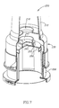
- Fig. 7 illustrates a two-compartment container assembly 200 according to another embodiment of the present invention where the container is assembled with a dispensing unit 210 and a cartridge unit 230.
- the bottom opening 218 of the dispensing unit 210 has a smaller diameter than in the previously described embodiments.
- the smaller diameter of the bottom opening 218 may be more suitable for an application requiring filling the dispensing unit 210 with a pressurized component.
- the sealing member 240 is accordingly smaller and thus the pressure exerted on the sealing member 240 by the internal pressure can be reduced. This minimizes the chance that the sealing member 240 might be pushed out of its sealed position before being assembled with a cartridge unit.
- the smaller diameter sealing member 240 has a plurality of J-shaped coupling arms 245 on the side facing the cartridge unit 230.
- the displaceable unit 256 is provided with top sealing wall 250 that sealingly engages with rim 232 when the displaceable member 256 is in its sealed position.
- a plurality of J-shaped coupling arms 255 is provide on the top surface of the top sealing wall 250 for coupling with the sealing member 240 by interlocking with the coupling arms 245.
- the coupling arms 245 and 255 are provided as a plurality of arms, similar to the coupling arms 45 and 55 in the container 100, but the coupling arms 245 and 255 are arranged in a circular formation with minimal spaces between each of the plurality of coupling arms.
- each group 245 and 255 may vary depending upon the particular application and would be a matter of design choice.
- These coupling arms 245 interlock with the coupling arms 255 by snap-fitting with when the dispensing unit 210 and the cartridge unit 230 are brought together for assembly.
- the coupling arms 245 and 255 are both arranged in a circular configuration with coupling arms 245 in a smaller diameter configuration.
- the coupling arms 245 and 255 are oriented so that the hook-end of the J-shaped profile of the coupling arms 245 are facing the hook-end of the J-shaped profile of the coupling arms 255.
- the coupling arms 245 and 255 elastically bend to allow the coupling arms 245 to slide inside the circle formed by the coupling arms 255 until they interlock.
- the rotational movement of the displaceable member 256 is not required to interlock the coupling arms 245 and 255.
- the coupling arms 245 and 255 may be solid circular structures.
- Figs. 8 illustrates another embodiment of a two-compartment container assembly 300 where the coupling mechanism between the dispensing unit's bottom sealing member and the top sealing wall of the cartridge unit is provided in a different configuration.
- the bottom sealing member 340 of the dispensing unit 310 has an extension 343 that protrudes downwardly and has an elliptically shaped bottom end having two ends 345 that extend beyond the extension 343.
- the top sealing wall 350 of the cartridge unit 330 has two coupling arms 355 that have a J-shaped profile.
- the coupling arms 355 are located equidistant from the center of the top sealing wall 350 with the hook-end of the J-shaped coupling arms 355 facing each other.
- the top opening of the dispensing unit 310 is sealed with a screw cap 320.
- Fig. 9 is a partial cutaway illustration of the fully assembled container assembly 300 and the configuration described above can be seen in more detail.
- the bottom opening of the dispensing unit 310 is sealed with a sealing member 340.
- the dispensing unit 310 and the cartridge unit 330 have been assembled together but the sealing member 340 and the top sealing wall 350 have not yet been coupled together.
- the dispensing unit 310 and the cartridge unit 330 are oriented so that the extending ends 345 of the elliptical bottom end of the sealing member 340 lie between the two coupling arms 355.
- the user would twist the dispensing unit 310 and the cartridge unit 330 in opposite directions about the longitudinal axis of the assembly, thereby causing the extending ends 345 of the elliptical bottom end of the sealing member 340 to slide under the hook end of the J-shaped coupling arms 355.
- Fig.10 illustrates the two-compartment container assembly 300 after the displaceable member 356 has been axially displaced to its unsealed position unsealing the coupled sealing member 340 and the top sealing wall 350.
- the top compartment 313 (defined by the internal space of the dispensing unit 310 ) and the bottom compartment 333 (defined by the internal space of the displaceable member 356 ) of the container assembly 300 are now in flow communication through the bottom opening 318 of the dispensing unit 310. has been pulled out of is sealing position leaving the bottom opening 318 of the dispensing unit 310 open.
- the bottom opening of the cartridge unit 330 is illustrated as being sealed with a closure member 360.
- the bottom end of the displaceable member 356 of the cartridge unit 330 may be configured and adapted to have a structure similar to that of the bottom end of the dispensing unit 310.
- a second cartridge unit may be engaged to the bottom end of the cartridge unit 330 to form a third compartment of the container assembly 300.
- a multi-compartment container system may be configured so that the dispensing unit is configured and adapted to hold a predetermined amount of substance.
- Such container may be used to store a bulk volume of a substance in the other compartments and use the dispensing unit to measure a predetermined single dose of the substance for dispensing.
- the bottom sealing member of the dispensing unit may be opened by axially displacing the displaceable member of the cartridge unit that is attached to the dispensing unit and let the contents of the cartridge unit fill the dispensing unit.
- the sealing member of the dispensing unit is resealed by axially displacing the displaceable member to its sealed position.
- the dispensing unit now is filled with a predetermined amount of the substance that may be dispensed through a separate dispensing opening on the top end of the dispensing unit.
Landscapes
- Engineering & Computer Science (AREA)
- Mechanical Engineering (AREA)
- Package Specialized In Special Use (AREA)
- Packages (AREA)
- Supplying Of Containers To The Packaging Station (AREA)
- Details Of Rigid Or Semi-Rigid Containers (AREA)
- Bag Frames (AREA)
- Filling Or Discharging Of Gas Storage Vessels (AREA)
- Closures For Containers (AREA)
- Medical Preparation Storing Or Oral Administration Devices (AREA)
- Packaging Of Annular Or Rod-Shaped Articles, Wearing Apparel, Cassettes, Or The Like (AREA)
Claims (6)
- Mehrfachabteilungsbehältersystem (100), umfassend:mindestens zwei Anordnungseinheiten;mindestens eine der Anordnungseinheiten ist eine Patroneneinheit (30), die umfasst:worin das verstellbare Element (56) zwischen einer abgedichteten Position, in der die Dichtungswand (50) mit dem Patronengehäuse in Eingriff steht, was die obere Endöffnung (36) des Patronengehäuses abdichtet, und einer nicht abgedichteten Position bewegt werden kann, in der die Dichtungswand (50) aus dem Eingriff mit dem Patronengehäuse gelöst vorliegt und wobei die obere Endöffnung (36) offen vorliegt, undein Patronengehäuse, das an dessen oberen und unteren Enden jeweils eine Öffnung (36, 38) aufweist;mindestens eine der zwei Öffnungen ist dazu angepasst und konfiguriert mit einer anderen Anordnungseinheit in Eingriff zu stehen und diese abzudichten;ein verstellbares Element (56), das an einem Ende eine Dichtungswand (50) aufweist, an dem anderen Ende einen manipulierbaren Bereich (52), der dazu angepasst und konfiguriert ist durch einen Benutzer gesteuert zu werden, um das verstellbare Element (56) zu bewegen, und mindestens ein Verbindungselement (58), das sich zwischen der Dichtungswand (50) und dem manipulierbaren Bereich (52) erstreckt,ein Verschlusselement (60), das die andere der zwei Öffnungen abdichtet,
die andere der mindestens zwei Anordnungseinheiten (10) weist mindestens eine mit einem Dichtungselement (40) abgedichtete Öffnung auf, wobei die mindestens eine Öffnung dazu angepasst und konfiguriert ist, um mit der oberen Endöffnung des Patronengehäuses im Eingriff zu stehen, wobei die Dichtungswand (50) und das Dichtungselement (40) jeweils mit mindestens einem Kopplungsarm (45, 55) bereitgestellt sind, die ineinander greifen, wenn die zwei Anordnungseinheiten angeordnet sind, wobei, wenn das verstellbare Element in dessen nicht abgedichtete Position bewegt wird, und die Dichtungswand (50) aus dem Eingriff mit dem Patronengehäuse löst, wird das Dichtungselement (40) ebenfalls aus dem Eingriff mit der mindestens einen Öffnung der anderen der mindestens zwei Anordnungseinheiten gelöst. - Mehrfachabteilungsbehältersystem nach Anspruch 1, worin die an der Dichtungswand und dem Dichtungselement bereitgestellten Kopplungsarme Vorsprünge mit Sperrleisten sind.
- Mehrfachabteilungsgehältersystem nach Anspruch 1, worin die an der Dichtungswand und dem Dichtungselement bereitgestellten Kopplungsarme Vorsprünge mit einem J-förmigen Profil sind.
- Mehrfachabteilungsgehältersystem nach Anspruch 1, worin die an der Dichtungswand und dem Dichtungselement bereitgestellten Kopplungsarme mehrere radial positionierte Vorsprünge mit Sperrleisten sind.
- Mehrfachabteilungsgehältersystem nach Anspruch 1, worin die an der Dichtungswand und dem Dichtungselement bereitgestellten Kopplungsarme mehrere radial positionierte Vorsprünge mit einem J-förmigen Profil sind.
- Mehrfachabteilungsgehältersystem nach Anspruch 1, worin die mindestens eine der oberen und unteren Öffnungen des Patronengehäuses mit Schraubengewinden bereitgestellt sind, um mit einer anderen Anordnungseinheit dichtend in Eingriff zu stehen.
Applications Claiming Priority (3)
| Application Number | Priority Date | Filing Date | Title |
|---|---|---|---|
| US10/294,020 US6959807B2 (en) | 2002-11-12 | 2002-11-12 | Multi-compartment container assembly system |
| US294020 | 2002-11-12 | ||
| PCT/IL2003/000950 WO2004043789A2 (en) | 2002-11-12 | 2003-11-12 | Multi compartment container assembly system |
Publications (3)
| Publication Number | Publication Date |
|---|---|
| EP1569854A2 EP1569854A2 (de) | 2005-09-07 |
| EP1569854A4 EP1569854A4 (de) | 2007-03-21 |
| EP1569854B1 true EP1569854B1 (de) | 2008-07-09 |
Family
ID=32229766
Family Applications (1)
| Application Number | Title | Priority Date | Filing Date |
|---|---|---|---|
| EP03772612A Expired - Lifetime EP1569854B1 (de) | 2002-11-12 | 2003-11-12 | Behälteranordnungssystem mit mehreren fächern |
Country Status (11)
| Country | Link |
|---|---|
| US (1) | US6959807B2 (de) |
| EP (1) | EP1569854B1 (de) |
| JP (1) | JP4236111B2 (de) |
| KR (1) | KR101069449B1 (de) |
| CN (1) | CN100363238C (de) |
| AT (1) | ATE400508T1 (de) |
| AU (1) | AU2003279505A1 (de) |
| DE (1) | DE60322098D1 (de) |
| ES (1) | ES2310674T3 (de) |
| RU (1) | RU2329926C2 (de) |
| WO (1) | WO2004043789A2 (de) |
Families Citing this family (26)
| Publication number | Priority date | Publication date | Assignee | Title |
|---|---|---|---|---|
| IL160784A (en) * | 2004-03-08 | 2011-02-28 | Mlis Projects Ltd | Cartridge unit for a multi-compartment container assembly |
| US7507701B2 (en) | 2005-02-25 | 2009-03-24 | Solutions Biomed, Llc | Aqueous disinfectants and sterilants including transition metals |
| US7534756B2 (en) * | 2005-02-25 | 2009-05-19 | Solutions Biomed, Llc | Devices, systems, and methods for dispensing disinfectant solutions comprising a peroxygen and transition metal |
| ZA200707893B (en) | 2005-02-25 | 2008-12-31 | Solutions Biomed Llc | Aqueous disinfectants and sterilants |
| US7473675B2 (en) * | 2005-02-25 | 2009-01-06 | Solutions Biomed, Llc | Disinfectant systems and methods comprising a peracid, alcohol, and transition metal |
| US7475564B2 (en) * | 2005-10-03 | 2009-01-13 | Kagen Kristin W | Container with sealed coolant compartment |
| IL177549A0 (en) * | 2006-08-17 | 2006-12-10 | Mlis Projects Ltd | Container and divider therefor |
| WO2009032203A1 (en) * | 2007-08-30 | 2009-03-12 | Solutions Biomed, Llc | Colloidal metal-containing skin sanitizer |
| US8146758B1 (en) * | 2008-03-07 | 2012-04-03 | Travis Peres | Compartmentalized baby bottle and associated method |
| US9016488B1 (en) * | 2008-03-07 | 2015-04-28 | Travis Peres | Compartmentalized mixing bottle and associated use therefore |
| US8464910B2 (en) | 2008-03-14 | 2013-06-18 | Solutions Biomed, Llc | Multi-chamber container system for storing and mixing fluids |
| US8834014B2 (en) * | 2008-03-24 | 2014-09-16 | Sashco, Inc. | System for providing custom colored sealing compound |
| US8800816B2 (en) * | 2009-03-24 | 2014-08-12 | Sashco, Inc. | System and method of providing individual quantities of custom colored sealing compound |
| WO2010056881A1 (en) | 2008-11-12 | 2010-05-20 | Solutions Biomed, Llc | Multi-chamber container system for storing and mixing liquids |
| US20100120913A1 (en) * | 2008-11-12 | 2010-05-13 | Larson Brian G | Resin catalyzed and stabilized peracid compositions and associated methods |
| US8716339B2 (en) | 2008-11-12 | 2014-05-06 | Solutions Biomed, Llc | Two-part disinfectant system and related methods |
| ES2437941T3 (es) * | 2011-03-11 | 2014-01-15 | Sulzer Mixpac Ag | Cartucho de múltiples componentes |
| EP2967260A1 (de) * | 2013-03-15 | 2016-01-20 | Christoph Zickler | Deckel für getränkebehälter |
| US11242236B2 (en) | 2015-03-19 | 2022-02-08 | Phillip LaBarbera | Perfect pour drink mixer |
| BE1023806B1 (fr) * | 2016-06-28 | 2017-07-27 | R&O Lab Sprl | Récipient de mélange adaptable à tout récipient récepteur |
| GB2559594B (en) * | 2017-02-10 | 2020-07-15 | Dexos Drinks Ltd | A liquid dispenser and method |
| EP3600303B1 (de) | 2017-08-15 | 2025-07-23 | Thomas Julius Borody | Zusammensetzung, umfassend ein rifaximin und eine kombination eines vancomycins, eines metronidazols und/oder eines tinidazols zur behandlung von autismus |
| CN112566848B (zh) * | 2018-06-01 | 2023-02-03 | 英灵集团有限公司 | 多隔室饮料瓶系统和方法 |
| US11478013B2 (en) * | 2020-05-29 | 2022-10-25 | Kyle Thomas Miller | Beverage container rimmer |
| CN115158889B (zh) * | 2022-09-05 | 2022-11-29 | 常州远望流体科技有限公司 | 包装瓶 |
| CN119389603B (zh) * | 2024-11-19 | 2025-12-26 | 深圳市真味生物科技有限公司 | 一种口含烟收纳盒 |
Family Cites Families (15)
| Publication number | Priority date | Publication date | Assignee | Title |
|---|---|---|---|---|
| DE3722371A1 (de) * | 1987-07-07 | 1989-01-19 | Henkel Kgaa | Zweikammerbehaelter |
| US5000314A (en) * | 1989-01-23 | 1991-03-19 | Bristol-Myers Company | Unit dose package |
| JPH05103819A (ja) * | 1991-08-08 | 1993-04-27 | Nissho Corp | 薬剤収容容器 |
| FR2680357B1 (fr) * | 1991-08-16 | 1995-01-06 | Oreal | Conditionnement a deux flacons permettant de stocker separement l'un de l'autre deux produits, notamment liquides, et de les melanger au moment de leur utilisation. |
| FR2694920B1 (fr) * | 1992-08-20 | 1994-10-28 | Oreal | Dispositif pour conserver séparés l'un de l'autre au moins deux produits et pour effectuer leur mélange à un instant souhaité. |
| FR2722765B1 (fr) * | 1994-07-25 | 1996-08-23 | Oreal | Recipient permettant le stockage d'au moins deux produits, le melange de ces produits et la distribution du melange ainsi obtenu |
| US5638968A (en) * | 1996-02-26 | 1997-06-17 | Baron; Moises S. | Baby bottle extension assembly having storage chamber and release mechanism |
| FR2751942B1 (fr) * | 1996-08-02 | 1998-09-11 | Oreal | Dispositif pour le stockage separe de deux composants leur melange et la distibution du melange |
| FR2751941B1 (fr) * | 1996-08-02 | 1998-09-11 | Oreal | Dispositif pour le conditionnement separe de deux composants, leur melange et la distribution du melange ainsi obtenu |
| DE19635833C2 (de) * | 1996-09-04 | 1998-08-06 | Henkel Kgaa | Zwei-Komponenten-Behälter |
| FR2759348B1 (fr) * | 1997-02-07 | 1999-04-16 | Biodome | Recipient distributeur multichambre pour le stockage d'au moins deux substances, le melange extemporane de celle-ci et la distribution du melange |
| BR9809632A (pt) * | 1997-05-15 | 2000-07-11 | R & D Injector Ag | Sistema de recipiente de dois componentes |
| FR2764868B1 (fr) * | 1997-06-20 | 1999-07-30 | Oreal | Dispositif de conditionnement d'un produit a plusieurs composantes devant etre stockees separement et melangees juste avant l'emploi du produit |
| FR2806271B1 (fr) * | 2000-03-17 | 2002-05-03 | Oreal | Dispositif pour le melange extemporane d'au moins deux produits |
| EP1414703B1 (de) * | 2001-08-06 | 2007-10-10 | M.L.I.S. Projects Ltd. | Behälteranordnungssystem mit mehreren fächern |
-
2002
- 2002-11-12 US US10/294,020 patent/US6959807B2/en not_active Expired - Fee Related
-
2003
- 2003-11-12 KR KR1020057008547A patent/KR101069449B1/ko not_active Expired - Fee Related
- 2003-11-12 CN CNB2003801080554A patent/CN100363238C/zh not_active Expired - Fee Related
- 2003-11-12 ES ES03772612T patent/ES2310674T3/es not_active Expired - Lifetime
- 2003-11-12 WO PCT/IL2003/000950 patent/WO2004043789A2/en not_active Ceased
- 2003-11-12 AU AU2003279505A patent/AU2003279505A1/en not_active Abandoned
- 2003-11-12 RU RU2005115442/12A patent/RU2329926C2/ru not_active IP Right Cessation
- 2003-11-12 EP EP03772612A patent/EP1569854B1/de not_active Expired - Lifetime
- 2003-11-12 DE DE60322098T patent/DE60322098D1/de not_active Expired - Lifetime
- 2003-11-12 AT AT03772612T patent/ATE400508T1/de not_active IP Right Cessation
- 2003-11-12 JP JP2004551133A patent/JP4236111B2/ja not_active Expired - Fee Related
Also Published As
| Publication number | Publication date |
|---|---|
| RU2329926C2 (ru) | 2008-07-27 |
| JP4236111B2 (ja) | 2009-03-11 |
| WO2004043789A3 (en) | 2005-03-03 |
| CN100363238C (zh) | 2008-01-23 |
| ATE400508T1 (de) | 2008-07-15 |
| US6959807B2 (en) | 2005-11-01 |
| US20040089563A1 (en) | 2004-05-13 |
| WO2004043789A2 (en) | 2004-05-27 |
| EP1569854A2 (de) | 2005-09-07 |
| KR20050072826A (ko) | 2005-07-12 |
| RU2005115442A (ru) | 2006-01-20 |
| ES2310674T3 (es) | 2009-01-16 |
| EP1569854A4 (de) | 2007-03-21 |
| AU2003279505A8 (en) | 2004-06-03 |
| KR101069449B1 (ko) | 2011-09-30 |
| CN1732111A (zh) | 2006-02-08 |
| JP2006519139A (ja) | 2006-08-24 |
| DE60322098D1 (de) | 2008-08-21 |
| AU2003279505A1 (en) | 2004-06-03 |
Similar Documents
| Publication | Publication Date | Title |
|---|---|---|
| EP1569854B1 (de) | Behälteranordnungssystem mit mehreren fächern | |
| US7083043B2 (en) | Multi-compartment container assembly system | |
| US8136660B2 (en) | Multi compartment container system | |
| US7861854B2 (en) | Cartridge unit for a multi-compartment container assembly | |
| AU2002324311A1 (en) | Multi-compartment container assembly system | |
| EP1687208B1 (de) | Kappe mit lagerungskammer für sekundärmaterial und produkt damit | |
| CA2572799A1 (en) | A syringe assembly | |
| KR100593246B1 (ko) | 용기 | |
| US12151871B2 (en) | Packaging system and corresponding method for handling a product preparation component | |
| IL250453A (en) | Container unit consisting of two containers | |
| KR20230054750A (ko) | 용기 마개 시스템 | |
| KR100433076B1 (ko) | 둘 이상의 격실을 가지는 용기 | |
| JPH1191831A (ja) | 混合分配容器 |
Legal Events
| Date | Code | Title | Description |
|---|---|---|---|
| PUAI | Public reference made under article 153(3) epc to a published international application that has entered the european phase |
Free format text: ORIGINAL CODE: 0009012 |
|
| 17P | Request for examination filed |
Effective date: 20050512 |
|
| AK | Designated contracting states |
Kind code of ref document: A2 Designated state(s): AT BE BG CH CY CZ DE DK EE ES FI FR GB GR HU IE IT LI LU MC NL PT RO SE SI SK TR |
|
| AX | Request for extension of the european patent |
Extension state: AL LT LV MK |
|
| DAX | Request for extension of the european patent (deleted) | ||
| A4 | Supplementary search report drawn up and despatched |
Effective date: 20070219 |
|
| RIC1 | Information provided on ipc code assigned before grant |
Ipc: B65D 25/08 20060101AFI20050623BHEP Ipc: B65D 81/32 20060101ALI20070213BHEP |
|
| GRAP | Despatch of communication of intention to grant a patent |
Free format text: ORIGINAL CODE: EPIDOSNIGR1 |
|
| GRAS | Grant fee paid |
Free format text: ORIGINAL CODE: EPIDOSNIGR3 |
|
| GRAA | (expected) grant |
Free format text: ORIGINAL CODE: 0009210 |
|
| AK | Designated contracting states |
Kind code of ref document: B1 Designated state(s): AT BE BG CH CY CZ DE DK EE ES FI FR GB GR HU IE IT LI LU MC NL PT RO SE SI SK TR |
|
| REG | Reference to a national code |
Ref country code: GB Ref legal event code: FG4D |
|
| REG | Reference to a national code |
Ref country code: CH Ref legal event code: EP |
|
| REF | Corresponds to: |
Ref document number: 60322098 Country of ref document: DE Date of ref document: 20080821 Kind code of ref document: P |
|
| REG | Reference to a national code |
Ref country code: IE Ref legal event code: FG4D |
|
| REG | Reference to a national code |
Ref country code: CH Ref legal event code: NV Representative=s name: BUECHEL, KAMINSKI & PARTNER PATENTANWAELTE ESTABLI |
|
| NLV1 | Nl: lapsed or annulled due to failure to fulfill the requirements of art. 29p and 29m of the patents act | ||
| REG | Reference to a national code |
Ref country code: ES Ref legal event code: FG2A Ref document number: 2310674 Country of ref document: ES Kind code of ref document: T3 |
|
| PG25 | Lapsed in a contracting state [announced via postgrant information from national office to epo] |
Ref country code: PT Free format text: LAPSE BECAUSE OF FAILURE TO SUBMIT A TRANSLATION OF THE DESCRIPTION OR TO PAY THE FEE WITHIN THE PRESCRIBED TIME-LIMIT Effective date: 20081209 Ref country code: NL Free format text: LAPSE BECAUSE OF FAILURE TO SUBMIT A TRANSLATION OF THE DESCRIPTION OR TO PAY THE FEE WITHIN THE PRESCRIBED TIME-LIMIT Effective date: 20080709 |
|
| PG25 | Lapsed in a contracting state [announced via postgrant information from national office to epo] |
Ref country code: BG Free format text: LAPSE BECAUSE OF FAILURE TO SUBMIT A TRANSLATION OF THE DESCRIPTION OR TO PAY THE FEE WITHIN THE PRESCRIBED TIME-LIMIT Effective date: 20081009 Ref country code: FI Free format text: LAPSE BECAUSE OF FAILURE TO SUBMIT A TRANSLATION OF THE DESCRIPTION OR TO PAY THE FEE WITHIN THE PRESCRIBED TIME-LIMIT Effective date: 20080709 Ref country code: AT Free format text: LAPSE BECAUSE OF FAILURE TO SUBMIT A TRANSLATION OF THE DESCRIPTION OR TO PAY THE FEE WITHIN THE PRESCRIBED TIME-LIMIT Effective date: 20080709 Ref country code: SI Free format text: LAPSE BECAUSE OF FAILURE TO SUBMIT A TRANSLATION OF THE DESCRIPTION OR TO PAY THE FEE WITHIN THE PRESCRIBED TIME-LIMIT Effective date: 20080709 |
|
| PG25 | Lapsed in a contracting state [announced via postgrant information from national office to epo] |
Ref country code: BE Free format text: LAPSE BECAUSE OF FAILURE TO SUBMIT A TRANSLATION OF THE DESCRIPTION OR TO PAY THE FEE WITHIN THE PRESCRIBED TIME-LIMIT Effective date: 20080709 |
|
| PG25 | Lapsed in a contracting state [announced via postgrant information from national office to epo] |
Ref country code: DK Free format text: LAPSE BECAUSE OF FAILURE TO SUBMIT A TRANSLATION OF THE DESCRIPTION OR TO PAY THE FEE WITHIN THE PRESCRIBED TIME-LIMIT Effective date: 20080709 Ref country code: EE Free format text: LAPSE BECAUSE OF FAILURE TO SUBMIT A TRANSLATION OF THE DESCRIPTION OR TO PAY THE FEE WITHIN THE PRESCRIBED TIME-LIMIT Effective date: 20080709 |
|
| PLBE | No opposition filed within time limit |
Free format text: ORIGINAL CODE: 0009261 |
|
| STAA | Information on the status of an ep patent application or granted ep patent |
Free format text: STATUS: NO OPPOSITION FILED WITHIN TIME LIMIT |
|
| PG25 | Lapsed in a contracting state [announced via postgrant information from national office to epo] |
Ref country code: SK Free format text: LAPSE BECAUSE OF FAILURE TO SUBMIT A TRANSLATION OF THE DESCRIPTION OR TO PAY THE FEE WITHIN THE PRESCRIBED TIME-LIMIT Effective date: 20080709 Ref country code: CZ Free format text: LAPSE BECAUSE OF FAILURE TO SUBMIT A TRANSLATION OF THE DESCRIPTION OR TO PAY THE FEE WITHIN THE PRESCRIBED TIME-LIMIT Effective date: 20080709 Ref country code: RO Free format text: LAPSE BECAUSE OF FAILURE TO SUBMIT A TRANSLATION OF THE DESCRIPTION OR TO PAY THE FEE WITHIN THE PRESCRIBED TIME-LIMIT Effective date: 20080709 |
|
| 26N | No opposition filed |
Effective date: 20090414 |
|
| PG25 | Lapsed in a contracting state [announced via postgrant information from national office to epo] |
Ref country code: MC Free format text: LAPSE BECAUSE OF NON-PAYMENT OF DUE FEES Effective date: 20081130 |
|
| REG | Reference to a national code |
Ref country code: IE Ref legal event code: MM4A |
|
| REG | Reference to a national code |
Ref country code: CH Ref legal event code: PFA Owner name: M.L.I.S. PROJECTS LTD. Free format text: M.L.I.S. PROJECTS LTD.#HARISHONIM STREET, P.O. BOX 342#42920 MOSHAV BEIT YITZHAK (IL) -TRANSFER TO- M.L.I.S. PROJECTS LTD.#HARISHONIM STREET, P.O. BOX 342#42920 MOSHAV BEIT YITZHAK (IL) |
|
| PG25 | Lapsed in a contracting state [announced via postgrant information from national office to epo] |
Ref country code: IE Free format text: LAPSE BECAUSE OF NON-PAYMENT OF DUE FEES Effective date: 20081112 |
|
| PG25 | Lapsed in a contracting state [announced via postgrant information from national office to epo] |
Ref country code: SE Free format text: LAPSE BECAUSE OF FAILURE TO SUBMIT A TRANSLATION OF THE DESCRIPTION OR TO PAY THE FEE WITHIN THE PRESCRIBED TIME-LIMIT Effective date: 20081009 |
|
| PG25 | Lapsed in a contracting state [announced via postgrant information from national office to epo] |
Ref country code: HU Free format text: LAPSE BECAUSE OF FAILURE TO SUBMIT A TRANSLATION OF THE DESCRIPTION OR TO PAY THE FEE WITHIN THE PRESCRIBED TIME-LIMIT Effective date: 20090110 Ref country code: CY Free format text: LAPSE BECAUSE OF FAILURE TO SUBMIT A TRANSLATION OF THE DESCRIPTION OR TO PAY THE FEE WITHIN THE PRESCRIBED TIME-LIMIT Effective date: 20080709 Ref country code: LU Free format text: LAPSE BECAUSE OF NON-PAYMENT OF DUE FEES Effective date: 20081112 |
|
| PG25 | Lapsed in a contracting state [announced via postgrant information from national office to epo] |
Ref country code: TR Free format text: LAPSE BECAUSE OF FAILURE TO SUBMIT A TRANSLATION OF THE DESCRIPTION OR TO PAY THE FEE WITHIN THE PRESCRIBED TIME-LIMIT Effective date: 20080709 |
|
| PG25 | Lapsed in a contracting state [announced via postgrant information from national office to epo] |
Ref country code: GR Free format text: LAPSE BECAUSE OF FAILURE TO SUBMIT A TRANSLATION OF THE DESCRIPTION OR TO PAY THE FEE WITHIN THE PRESCRIBED TIME-LIMIT Effective date: 20081010 |
|
| PGFP | Annual fee paid to national office [announced via postgrant information from national office to epo] |
Ref country code: ES Payment date: 20111125 Year of fee payment: 9 |
|
| PGFP | Annual fee paid to national office [announced via postgrant information from national office to epo] |
Ref country code: GB Payment date: 20130521 Year of fee payment: 10 Ref country code: DE Payment date: 20130522 Year of fee payment: 10 Ref country code: CH Payment date: 20130523 Year of fee payment: 10 |
|
| PGFP | Annual fee paid to national office [announced via postgrant information from national office to epo] |
Ref country code: IT Payment date: 20130528 Year of fee payment: 10 Ref country code: FR Payment date: 20130610 Year of fee payment: 10 |
|
| REG | Reference to a national code |
Ref country code: CH Ref legal event code: PL |
|
| GBPC | Gb: european patent ceased through non-payment of renewal fee |
Effective date: 20131112 |
|
| PG25 | Lapsed in a contracting state [announced via postgrant information from national office to epo] |
Ref country code: CH Free format text: LAPSE BECAUSE OF NON-PAYMENT OF DUE FEES Effective date: 20131130 Ref country code: LI Free format text: LAPSE BECAUSE OF NON-PAYMENT OF DUE FEES Effective date: 20131130 |
|
| REG | Reference to a national code |
Ref country code: FR Ref legal event code: ST Effective date: 20140731 |
|
| PG25 | Lapsed in a contracting state [announced via postgrant information from national office to epo] |
Ref country code: DE Free format text: LAPSE BECAUSE OF NON-PAYMENT OF DUE FEES Effective date: 20140603 Ref country code: IT Free format text: LAPSE BECAUSE OF NON-PAYMENT OF DUE FEES Effective date: 20131112 |
|
| REG | Reference to a national code |
Ref country code: DE Ref legal event code: R119 Ref document number: 60322098 Country of ref document: DE Effective date: 20140603 |
|
| PG25 | Lapsed in a contracting state [announced via postgrant information from national office to epo] |
Ref country code: FR Free format text: LAPSE BECAUSE OF NON-PAYMENT OF DUE FEES Effective date: 20131202 Ref country code: GB Free format text: LAPSE BECAUSE OF NON-PAYMENT OF DUE FEES Effective date: 20131112 |
|
| REG | Reference to a national code |
Ref country code: ES Ref legal event code: FD2A Effective date: 20150709 |
|
| PG25 | Lapsed in a contracting state [announced via postgrant information from national office to epo] |
Ref country code: ES Free format text: LAPSE BECAUSE OF NON-PAYMENT OF DUE FEES Effective date: 20131113 |