EP1569812B1 - Motor vehicle door - Google Patents
Motor vehicle door Download PDFInfo
- Publication number
- EP1569812B1 EP1569812B1 EP03767439A EP03767439A EP1569812B1 EP 1569812 B1 EP1569812 B1 EP 1569812B1 EP 03767439 A EP03767439 A EP 03767439A EP 03767439 A EP03767439 A EP 03767439A EP 1569812 B1 EP1569812 B1 EP 1569812B1
- Authority
- EP
- European Patent Office
- Prior art keywords
- door
- window
- window pane
- motor vehicle
- vehicle door
- Prior art date
- Legal status (The legal status is an assumption and is not a legal conclusion. Google has not performed a legal analysis and makes no representation as to the accuracy of the status listed.)
- Expired - Fee Related
Links
Images


Classifications
-
- B—PERFORMING OPERATIONS; TRANSPORTING
- B60—VEHICLES IN GENERAL
- B60J—WINDOWS, WINDSCREENS, NON-FIXED ROOFS, DOORS, OR SIMILAR DEVICES FOR VEHICLES; REMOVABLE EXTERNAL PROTECTIVE COVERINGS SPECIALLY ADAPTED FOR VEHICLES
- B60J5/00—Doors
- B60J5/04—Doors arranged at the vehicle sides
- B60J5/042—Reinforcement elements
- B60J5/0422—Elongated type elements, e.g. beams, cables, belts or wires
- B60J5/0423—Elongated type elements, e.g. beams, cables, belts or wires characterised by position in the lower door structure
- B60J5/0426—Elongated type elements, e.g. beams, cables, belts or wires characterised by position in the lower door structure the elements being arranged at the beltline
-
- B—PERFORMING OPERATIONS; TRANSPORTING
- B60—VEHICLES IN GENERAL
- B60J—WINDOWS, WINDSCREENS, NON-FIXED ROOFS, DOORS, OR SIMILAR DEVICES FOR VEHICLES; REMOVABLE EXTERNAL PROTECTIVE COVERINGS SPECIALLY ADAPTED FOR VEHICLES
- B60J5/00—Doors
- B60J5/04—Doors arranged at the vehicle sides
- B60J5/042—Reinforcement elements
- B60J5/0456—Behaviour during impact
- B60J5/0459—Active coupling of the reinforcement elements to the door or to the vehicle body, e.g. through releasing of pressurized gas
Definitions
- the invention relates to a motor vehicle door according to the preamble of claim 1.
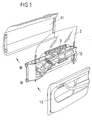
- FIG. 1 and the longitudinal section through a motor vehicle door according to FIG. 2 of interconnected door shells 11, 12, of which the outer door shell or the outer door panel 11 adapted to the vehicle body and the inner door panel or the inner door panel 12 with a Door inner panel 13 is connected.
- a door shaft 10 is formed, are arranged in the various door units, including a window 3 for raising and lowering a window 2 from and into the door shaft 10, if necessary, on a door module carrier.
- the upper end of the door shaft 10 forms a door channel strip 14, through which the window pane 2 exits when lifting through the window regulator 3 from the door shaft 10 and closes a door opening provided above the door opening 10.
- a motor vehicle door is known in which for ease of handling in mass production or for use of a robot system in the connection with a door components such as a door lock, an operating rod with holding device for the door lock, a movable window, a window and the like preassembled modular inner shell with a deep-drawn outer shell with a window frame and hinges for fastening the motor vehicle door to a vehicle body, the outer shell at the lateral ends of the window frame has two locking elements for a cross-connection of the modular inner shell with the outer shell.
- a door components such as a door lock, an operating rod with holding device for the door lock, a movable window, a window and the like preassembled modular inner shell with a deep-drawn outer shell with a window frame and hinges for fastening the motor vehicle door to a vehicle body
- the outer shell at the lateral ends of the window frame has two locking elements for a cross-connection of the modular inner shell with the outer shell.
- the two provided at the lateral ends locking elements are pivotally mounted on a plane perpendicular to the surface of the outer shell level and have an insertion part for receiving the modular inner shell, which is biased by a return spring in the direction of the outer shell. Furthermore, the insertion part for receiving the modular inner shell contains a stop which can be locked with a hook when the modular inner shell has assumed its position of use on the outer shell. In the use position, the window pane engages in the lateral guide rails of the window lifter into the upper part of the outer shell.
- the object of the present invention is to increase the safety of a motor vehicle door without limiting the space requirement and the mobility of the window lifter or the window pane.
- the solution according to the invention ensures increased safety of the door body of a motor vehicle door without function restrictions or structural limitations of the window lifter or the window pane of a motor vehicle door.
- the component is designed as a force-transmitting and / or as a door gap-covering component.
- the component extends at least over the area of the door lock and / or associated with the door lock parts such as linkage, Bowden and the like.
- stiffening elements of the door body By connecting the window pane or the window lifter with the door outer shell and / or the door inner shell stiffening elements of the door body can be connected to each other so that the door body acts as a closed unit.
- a non-positive and / or positive connection of the window or the window with the outer door shell and / or the door inner shell or the door outer shell directly with the inner door shell increased rigidity is achieved, the in side and front crash situations, the safety of the vehicle door significantly increased without additional stiffening measures made to the outer door shell and / or door inner shell or the strength of the material of the door shells themselves must be increased.
- the force-transmitting component can be attached directly to the window or directly to the window and support the structure of the door body in the upper stop of the window or on the disc hub to tensile or compressive load.
- At least one component is connected to a door shell and resiliently supported on the window or the window.
- the component can be designed as a component that is variable in position with the movement of the window pane or of the window lifter and that connects positively to a door shell in the case of a predetermined position of the window pane or the window lifter.
- the component can rest against the window pane or the window lifter with pretension and, when the window pane or the window lifter is raised, pivot out of the door shaft into a force-transmitting position with a door shell by means of a catch or support arranged on the window pane or window lifter.
- the component has in particular a variable-length pivot arm and connected to the pivot arm bridging, one end of a slider on the window or the window rests and the other end for connection to a door shell at a predetermined position of the window or the window regulator engages in an undercut of the door shell.
- the swivel arm can be designed as a telescopic arm and be hinged to a door shell and biased by a torsion spring against the window pane or the window regulator.
- the component can be supported on the window pane or the window lifter essentially at right angles to the window pane or the window lifter, said element being in the fully raised position of the window pane or the window lifter on a catch connected to the window pane or the window lifter or support abuts.
- the component may be connected to a windshield wiper or windshield washer and thus easily perform an additional function.
- the solution according to the invention makes it possible, alternatively or in addition to a pure covering function, in particular to improve the security against burglary, to reinforce the crashworthiness of the vehicle door by connecting the component to the window pane or to the window lifter and, preferably, to a predeterminable position of the window pane or the window lifter in the upper end position of the window or the window, at least creates a frictional connection between the door shells.
- the component has connecting arms assigned to the door shells, whose contour substantially coincides with the contour of the door shells in the engagement region of the component with the door shells.
- the contour of the connecting arms at least that of the connecting arm oriented towards the door outer shell, can enclose a water drainage channel and thus protect the door fittings from moisture.
- the component preferably consists of securing elements connected to the door shells and a connecting element connected to the window pane or the window lifter and preferably fastened to the lower edge of the window pane or the window lifter, which in a predeterminable position of the window pane or of the window lifter, preferably in the upper end position of the window pane or the window regulator, at least non-positively connected to the riveted to the door shells, welded or formed as part of an extruded profile of the door shells securing elements.
- connection between the securing elements and the connecting element can take place via securing bolts.
- the securing elements may be perforated or slotted in the connecting region with the connecting element and have the connecting element with aligned on the perforation or the slots of the securing elements engaging portions which engage in the predetermined, in particular uppermost position of the window or the window regulator in the securing elements.
- the securing elements and the connecting element can produce a positive connection in the manner of a toothing.
- the solution according to the invention provides a reduction in the shell weight of the motor vehicle door, a significant improvement in burglary protection, an improvement of the front and side crash situation of the motor vehicle door, allows additional functions for the window, for example by the integration of wiping, rinsing and washing facilities and protects the interior of the Door body or the door shaft by integrating a Wasserableitrinne in the force-transmitting component, so that arranged in the door shaft functional elements of a motor vehicle door, regardless of whether they are located in the wet or dry space area of the door shaft, are better protected against moisture.
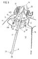
- FIG 3 shows a section through a door body in the region of the door shaft strip 14 in which sealing elements 31, 32 connected to the door outer shell 11 or the inner door shell 12 are arranged and can be lifted from the door shaft 10 or moved in the direction of the double arrow the door shaft 10 lowerable window pane 2 abut.
- the window pane 2 is shown in three different movement sections A, B and C, namely in a lowered position in the door shaft 10 A, a middle position B and an uppermost, that is substantially lifted out of the door shaft 10 position C.
- the components 4, 4 ' Due to a torsion spring 40 or 40 'arranged at the points of articulation of the components 4, 4', the components 4, 4 'are prestressed in the direction of the arrows V and abut with the upper side of the bridging arms 42, 42' on the outer surface of the window pane 2, if this is in the door shaft 10.
- the end 422 of the bridging arms 42, 42 ', on which the dogs 21, 21' engage is provided with a slider to reduce the friction between the surface of the window glass 2 and the bridging arms 42, 42 '.
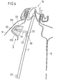
- the component 5 shown in FIG. 4 has a similar function as the component 4 shown in FIG. 3, but is not pivotally attached to the outer door shell, but arranged with a base body 53 in a recess 111 of the parapet reinforcement 110 of the door outer shell 11.
- a securing arm 51 of the component 5 is guided substantially perpendicular to the plane of the window pane 2 in the base body 53 and resiliently supported therefrom by means of a compression spring 50, so that the securing arm 51 with its end opposite the compression spring 50 preferably has a slider or a sliding roller 52 is supported on the outside of the window pane 2. Due to the guidance of the securing arm 51 in the base body 53 is given sufficient strength and security against kinking of the securing arm 51, so that an engagement in the door shaft 10 via the door shaft strip 14 is at least substantially more difficult.
- An additional security against external interference can analogous to the arrangement of FIG. 3 cause a connected to the lower edge 20 of the window pane 2 driver 21 which rests firmly in the uppermost position of the window 2 on the safety arm 51 and thus bending or kinking of the securing arm 51st prevented.
- the component 4 or 5 shown in FIGS. 3 and 4 may additionally be connected to a windshield wiper and / or windshield washer device, which cleans the surface of the window pane 2 with each movement of the window pane 2.
- a component 5 corresponding component between the inner door shell 12 and the window pane 2 are arranged so that in the uppermost position of the window pane 2, a direct connection between the two components on the lower edge of the window 20 and the the lower edge 20 fixed driver 21 are made, which increases the crash safety of the motor vehicle door by the frictional connection between the door shells 11, 12.
- the driver 21 may be formed on the lower edge 20 of the window pane 2 so that the securing arms 51 engage in the uppermost position of the window pane 2 in corresponding recess of the driver 21 and thus an immediate non-positive connection Locking arms on the driver 21 cause.
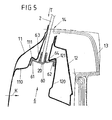
- FIG. 5 shows, in a section through the door body in the region of the door channel strip 14, a further variant of the solution according to the invention, in which the lower edge 20 of the window pane 2 is connected to a force-transmitting component 6, which in the uppermost position of the window pane 2 forms a frictional connection between Parapet reinforcements 110, 120 of the door outer shell 11 and the inner door shell 12 produces.
- the component 6 a connecting portion 60 embracing the lower edge 20 and on both sides of the connecting portion 60 connecting arms 61, 62 corresponding to the contour of recess or indentations 111, 121 of the parapet reinforcements 110, 120 of the door outer shell 11 and the inner door shell 12.
- the contours of the connecting arms 61, 62 are chosen so that water drainage channels 63, 64 are formed, which prevent the manner of a gutter that penetrates via the door shaft molding 14 penetrating moisture on arranged in the door body door components.
- the component can be fastened directly to the window lifter for raising and lowering the window pane 2, and it does not depend on the type of window regulator, i. arrives at the arrangement of a Wienarm- or cable window lifter.
- the component 6 can be attached to a connected to the lower edge of the disc 20 continuous rail.
- Fig. 6 shows an embodiment in which the force-transmitting member 7 is not positively locking with locking arms in corresponding positive locking portions of the door shells 11, 12 engages, but is formed in several parts and in the closed position of the window 2 produces a positive connection between its individual components.
- the force-transmitting component 7 consists of a connecting element 70 connected to the lower edge 20 of the window pane 2 or to a suitable part of a window lifter for raising and lowering the window pane 2 and one connected to the parapet reinforcement 110 of the outer door shell 11 and the parapet reinforcement 120 of the inner door shell 12, respectively Securing element 71, 72 which engage in the closed position of the window pane 2 via securing bolts 73, 74 in the connecting element 70.
- the securing elements 71, 72 are connected by means of rivets 75, 76 with the parapet reinforcements 110, 120 of the door shells 11, 12 or welded or glued thereto.
- connection of the connecting element 70 with the lower edge 20 of the window pane 2 can be done by gluing or positive locking or gluing and positive locking or by a pin or screw connection.
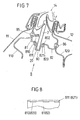
- Fig. 7 shows a the door shells 11, 12 in the closed position of the window 2 frictionally interconnecting component 8, consisting of a connected to the lower edge 20 of the window glass 2 connecting member 80 and the parapet reinforcements 110, 120 of the door shells 11, 12 connected fuse arms 81st , 82 which engage in the closed position of the window pane 2 positively in the connecting element 80.
- the securing arms 81, 82 are connected via rivet or screw 85, 86 with the parapet reinforcements 110, 120 of the door shells 11, 12 and 8 as shown in FIG.
- the connecting element 80 may alternatively or additionally be connected to a window regulator moving the window pane 2.
- FIG. 9 likewise shows a section through a door shaft 10 of a door body in the region of the door shaft strip 14 with a force-transmitting component 9, each having a securing element 91 connected to the outer door shell 11 and the inner door shell 12, 92 and a connecting element 90 has.
- the securing elements 91, 92 may be formed as an extruded profile and may be part of the outer shell 11 and the inner shell 12, respectively.
- the connecting element 90 is connected to the lower edge 20 of the window pane 2 by, for example, adhering it to the lower edge 20 with a region 900 comprising the lower edge 20.
- the connecting element 90 has two connecting arms 903, 904, which are formed as running along the free lower edge box sections to reduce the distance of the connecting element to the parapet reinforcements 110, 120 of the door outer shell 11 and the inner door shell 12, which additionally by a profiling a minimum Distance to the connecting arms 903, 904 create.
- connection between the connecting arms 903, 904 and the securing elements 91, 92 is produced according to FIG. 10 in the manner of a toothing, in which of the connecting arms 90, 904 of the connecting element 90 protruding teeth 901, 902 in recesses 910 and 920 of the securing elements 91st , 92 intervene.
- the box profile of the securing elements 91, 92 additionally serves as a side impact carrier in order to reduce side impact forces acting on the motor vehicle door.
- the toothings 901 of the connecting arms 903, 904 of the connecting element 90 can be provided with an undercut 905 in accordance with FIG. 11 in order to ensure the engagement of the toothings 901, 902 in the recesses 910, 920 of the securing elements 91, 92 formed as counterprofiles.
- Fig. 12 shows schematically a further variant of the connection between a connecting element 90 'and the securing elements 91', 92 ', in which a positive connection in the Y direction of the motor vehicle is produced without holes or recesses and which is particularly suitable in one embodiment as an extruded profile ,
- the ends of the connecting arms 901 ', 902' of the connecting element 90 ' which is placed with a region 900' around the lower edge 20 of the window pane 2 and connected thereto by gluing, engage around the ends of the securing elements 91 ', 92' according to Art one Clamp and thereby provide a force-transmitting connection between the door shells 11, 12 of FIG. 9 ago.
- the embodiments described above illustrate the various ways of realizing the underlying idea of the invention for securing a motor vehicle door against burglary and to improve the front and side impact protection.
- Common to all embodiments is the closing of the upper door slot slot, at least when the window pane is raised completely out of the door shaft, so that effective theft protection is ensured.
- Alternative embodiments additionally provide a force-transmitting connection between the door shells of the motor vehicle door so that frontal and side impact forces are absorbed better by increasing the inherent rigidity of the door body.
- the additional material and assembly costs is low compared to otherwise required additional measures for lock cover to improve the theft protection or to increase the inherent rigidity of the door shells by appropriate profiling or stronger materials that lead to an increase in the dead weight of the vehicle door and thus the motor vehicle.
Description
Die Erfindung betrifft eine Kraftfahrzeugtür gemäß dem Oberbegriff des Anspruchs 1.The invention relates to a motor vehicle door according to the preamble of
Eine Kraftfahrzeugtür 1 besteht entsprechend der perspektivischen Explosionsdarstellung gemäß Fig. 1 und dem Längsschnitt durch eine Kraftfahrzeugtür gemäß Fig. 2 aus miteinander verbundenen Türschalen 11, 12, von denen die Türaußenschale oder das Türaußenblech 11 der Kraftfahrzeugkarosserie angepasst und die Türinnenschale oder das Türinnenblech 12 mit einer Türinnenverkleidung 13 verbunden ist. Zwischen der Türaußenschale 11 und der Türinnenschale 12 ist ein Türschacht 10 ausgebildet, in dem verschiedene Türaggregate, unter anderem ein Fensterheber 3 zum Anheben und Absenken einer Fensterscheibe 2 aus dem und in den Türschacht 10 ggf. auf einem Türmodulträger angeordnet sind. Den oberen Abschluss des Türschachtes 10 bildet eine Türschachtleiste 14, durch die die Fensterscheibe 2 beim Anheben durch den Fensterheber 3 aus dem Türschacht 10 austritt und eine oberhalb des Türschachtes 10 vorgesehene Türöffnung verschließt.1 and the longitudinal section through a motor vehicle door according to FIG. 2 of interconnected
Durch die Anordnung der mittels des Fensterhebers 3 aufwärts und abwärts beweglichen Fensterscheibe 2 ist eine konstruktive Verbindung zwischen der Türaußenschale 11 und der Türinnnenschale 12 innerhalb des Türschachtes 10 nicht möglich, da der Türrohbau bzw. der Türkörper infolge der Fensterscheibe 2 bzw. des Fensterhebers 3 zweigeteilt ist, so dass sowohl die Türaußenschale 11 als auch die Türinnenschale 12 mit ihrer Eigensteifigkeit den Türrohbau und dessen Steifigkeit definieren, die im Verbund von Türaußenschale und Türinnenschale durch eine kraftschlüssige Verbindung wesentlich höher wäre. Die Steifigkeit der Kraftfahrzeugtür ist daher gegenüber der Kraftfahrzeugkarosserie herabgesetzt, da diese eine kraftschlüssige Verbindung zwischen der Außenschale und der Innenschale zulässt und damit größere Aufprallsicherheiten gegenüber Seiten- und Frontcrashsituationen bietet.The arrangement of the window by means of the
Zur Anpassung der Seiten- und Frontcrashsicherheit einer Kraftfahrzeugtür an die Kraftfahrzeugkarosserie wäre nur durch die Verwendung stärkerer Materialien für die Türschalen oder durch zusätzliche Versteifungen der Türaußenschale 11 und der Türinnenschale 12 möglich. Durch beide Maßnahmen wird jedoch das Gewicht der Kraftfahrzeugtür deutlich erhöht.To adapt the side and front crash safety of a motor vehicle door to the vehicle body would be possible only by the use of stronger materials for the door shells or by additional stiffening the door
Ein weiteres Problem bei der Konstruktion von Kraftfahrzeugtüren besteht darin, dass die obere Türschachtleiste 14 sowohl in Bezug auf Witterungseinflüsse als auch in Bezug auf Einbruchsicherheit eine Schwachstelle darstellt. Trotz der Anordnung von Abdichtungselementen, die dichtend an der Fensterscheibe 2 anliegen, besteht die Gefahr des Eintritts von Feuchtigkeit in den Türschacht 10, insbesondere bei gealterten oder beschädigten Abdichtungselementen. Um einen Einbruch in den Türschließmechanismus von außen zu verhindern, der über die offene Türschachtleiste 14 sehr einfach ist, müssen mit erheblichen Aufwand und Kosten Schlossabdeckungen vorgesehen werden, die einen Einbruch in das Kraftfahrzeug zumindest erschweren.Another problem in the design of automotive doors is that the
Aus der FR 2 626 534 ist eine Kraftfahrzeugtür bekannt, bei der zur Vereinfachung der Handhabung in der Serienfertigung bzw. zum Einsatz eines Robotersystems bei der Verbindung einer mit Türkomponenten wie einem Türschloss, einer Betätigungsstange mit Haltevorrichtung für das Türschloss, einer beweglichen Fensterscheibe, einem Fensterheber und dgl. vorbestückten modularen Innenschale mit einer tiefgezogenen Außenschale mit einem Fensterrahmen und Scharnieren zur Befestigung der Kraftfahrzeugtür an einer Fahrzeugkarosserie die Außenschale an den seitlichen Enden des Fensterrahmens zwei Verriegelungselemente für eine Querverbindung der modularen Innenschale mit der Außenschale aufweist. Die beiden an den seitlichen Enden vorgesehenen Verriegelungselemente sind schwenkbar an einer senkrecht zur Fläche der Außenschale verlaufenden Ebene befestigt und weisen ein Einführteil zur Aufnahme der modularen Innenschale auf, das mittels einer Rückstellfeder in Richtung der Außenschale vorgespannt ist. Weiterhin enthält das Einführteil zur Aufnahme der modularen Innenschale einen Anschlag, der mit einem Haken verriegelbar ist, wenn die modulare Innenschale ihre Gebrauchsstellung an der Außenschale eingenommen hat. In der Gebrauchsstellung greift die Fensterscheibe in die seitlichen Führungsschienen des Fensterhebers in den oberen Teil der Außenschale ein.From FR 2 626 534 a motor vehicle door is known in which for ease of handling in mass production or for use of a robot system in the connection with a door components such as a door lock, an operating rod with holding device for the door lock, a movable window, a window and the like preassembled modular inner shell with a deep-drawn outer shell with a window frame and hinges for fastening the motor vehicle door to a vehicle body, the outer shell at the lateral ends of the window frame has two locking elements for a cross-connection of the modular inner shell with the outer shell. The two provided at the lateral ends locking elements are pivotally mounted on a plane perpendicular to the surface of the outer shell level and have an insertion part for receiving the modular inner shell, which is biased by a return spring in the direction of the outer shell. Furthermore, the insertion part for receiving the modular inner shell contains a stop which can be locked with a hook when the modular inner shell has assumed its position of use on the outer shell. In the use position, the window pane engages in the lateral guide rails of the window lifter into the upper part of the outer shell.
Aufgabe der vorliegenden Erfindung ist es, die Sicherheit einer Kraftfahrzeugtür ohne Einschränkung des Platzbedarfs und der Beweglichkeit des Fensterhebers oder der Fensterscheibe zu erhöhen.The object of the present invention is to increase the safety of a motor vehicle door without limiting the space requirement and the mobility of the window lifter or the window pane.
Diese Aufgabe wird erfindungsgemäß durch die Merkmale des Anspruchs 1 gelöst.This object is achieved by the features of
Die erfindungsgemäße Lösung gewährleistet eine erhöhte Sicherheit des Türkörpers einer Kraftfahrzeugtür ohne Funktionseinschränkungen oder bauliche Beschränkungen des Fensterhebers oder der Fensterscheibe einer Kraftfahrzeugtür.The solution according to the invention ensures increased safety of the door body of a motor vehicle door without function restrictions or structural limitations of the window lifter or the window pane of a motor vehicle door.
Wesentlich bei der Realisierung der erfindungsgemäßen Lösung ist, dass das Bauteil als kraftübertragendes und/oder als ein den Türspalt abdeckendes Bauteil ausgebildet ist.Essential in the realization of the solution according to the invention is that the component is designed as a force-transmitting and / or as a door gap-covering component.
Zur Einbruchssicherung erstreckt sich das Bauteil wenigstens über den Bereich des Türschlosses und/oder der mit dem Türschloss verbundenen Teile wie Gestänge, Bowden und dergleichen.For burglary protection, the component extends at least over the area of the door lock and / or associated with the door lock parts such as linkage, Bowden and the like.
Durch die Verbindung der Fensterscheibe bzw. des Fensterhebers mit der Türaußenschale und/oder der Türinnenschale können Versteifungselemente des Türkörpers so miteinander verbunden werden, dass der Türkörper als geschlossene Einheit wirkt. Durch eine kraft- und/oder formschlüssige Verbindung der Fensterscheibe bzw. des Fensterhebers mit der Türaußenschale und/oder der Türinnenschale oder der Türaußenschale unmittelbar mit der Türinnenschale wird eine erhöhte Eigensteifigkeit erzielt, die bei Seiten- und Frontcrashsituationen die Sicherheit der Kraftfahrzeugtür deutlich erhöht, ohne dass zusätzliche Versteifungsmaßnahmen an der Türaußenschale und/oder Türinnenschale vorgenommen oder die Festigkeit des Materials der Türschalen selbst erhöht werden muss. Das kraftübertragende Bauteil kann unmittelbar am Fensterheber oder direkt an der Fensterscheibe befestigt werden und die Struktur des Türkörpers im oberen Anschlag des Fensterhebers oder über den Scheibenhub auf Zug- oder Druckbelastung unterstützen.By connecting the window pane or the window lifter with the door outer shell and / or the door inner shell stiffening elements of the door body can be connected to each other so that the door body acts as a closed unit. By a non-positive and / or positive connection of the window or the window with the outer door shell and / or the door inner shell or the door outer shell directly with the inner door shell increased rigidity is achieved, the in side and front crash situations, the safety of the vehicle door significantly increased without additional stiffening measures made to the outer door shell and / or door inner shell or the strength of the material of the door shells themselves must be increased. The force-transmitting component can be attached directly to the window or directly to the window and support the structure of the door body in the upper stop of the window or on the disc hub to tensile or compressive load.
Auch bei alleiniger Anordnung eines kraftübertragenden Bauteils zwischen der Fensterscheibe bzw. dem Fensterheber und einer der beiden Türschalen erhöht die erfindungsgemäße Lösung die Sicherheit der Kraftfahrzeugtür gegen Fremdeingriffe, da das Bauteil die obere Öffnung des Türschachtes verschließt und damit den Zugang zum Türschloss über die Türschachtleiste blockiert. Dadurch werden zusätzliche Sicherungsmaßnahmen zum Schutz des Türschlosses beispielsweise mittels einer Türschlossabdeckung überflüssig.Even with the sole arrangement of a force-transmitting component between the window or the window and one of the two door shells solution of the invention increases the safety of the vehicle door against interference, since the component closes the upper opening of the door shaft and thus blocks access to the door lock on the door shaft strip. As a result, additional security measures to protect the door lock, for example by means of a door lock cover superfluous.
Dementsprechend ist mindestens ein Bauteil mit einer Türschale verbunden und federelastisch an der Fensterscheibe oder dem Fensterheber abgestützt.Accordingly, at least one component is connected to a door shell and resiliently supported on the window or the window.
Das Bauteil kann als ein mit der Bewegung der Fensterscheibe oder des Fensterhebers lageveränderliches Bauteil ausgebildet werden, das sich bei einer vorgegebenen Stellung der Fensterscheibe oder des Fensterhebers formschlüssig mit einer Türschale verbindet. Insbesondere kann das Bauteil mit Vorspannung an der Fensterscheibe oder am Fensterheber anliegen und beim Anheben der Fensterscheibe oder des Fensterhebers aus dem Türschacht mittels eines an der Fensterscheibe oder am Fensterheber angeordneten Mitnehmers oder Auflagers in eine kraftübertragende Stellung mit einer Türschale verschwenken.The component can be designed as a component that is variable in position with the movement of the window pane or of the window lifter and that connects positively to a door shell in the case of a predetermined position of the window pane or the window lifter. In particular, the component can rest against the window pane or the window lifter with pretension and, when the window pane or the window lifter is raised, pivot out of the door shaft into a force-transmitting position with a door shell by means of a catch or support arranged on the window pane or window lifter.
In dieser Variante der erfindungsgemässen Lösung weist das Bauteil insbesondere einen längenveränderlichen Schwenkarm und einen mit dem Schwenkarm verbundenen Überbrückungsarm auf, dessen eines Ende über ein Gleitstück an der Fensterscheibe oder dem Fensterheber anliegt und dessen anderes Ende zur Verbindung mit einer Türschale bei einer vorgegebenen Stellung der Fensterscheibe oder des Fensterhebers in einen Hinterschnitt der Türschale eingreift. Dabei kann der Schwenkarm als Teleskoparm ausgebildet und an einer Türschale angelenkt sowie über eine Drehfeder gegen die Fensterscheibe oder den Fensterheber vorgespannt sein.In this variant of the inventive solution, the component has in particular a variable-length pivot arm and connected to the pivot arm bridging, one end of a slider on the window or the window rests and the other end for connection to a door shell at a predetermined position of the window or the window regulator engages in an undercut of the door shell. In this case, the swivel arm can be designed as a telescopic arm and be hinged to a door shell and biased by a torsion spring against the window pane or the window regulator.
In einer alternativen Ausführungsform kann das Bauteil im wesentlichen rechtwinklig zur Fensterscheibe oder zum Fensterheber beweglich und federelastisch an der Fensterscheibe oder dem Fensterheber abgestützt werden, wobei das Bauteil in der vollständig angehobenen Stellung der Fensterscheibe oder des Fensterhebers an einem mit der Fensterscheibe oder dem Fensterheber verbundenen Mitnehmer oder Auflager anliegt.In an alternative embodiment, the component can be supported on the window pane or the window lifter essentially at right angles to the window pane or the window lifter, said element being in the fully raised position of the window pane or the window lifter on a catch connected to the window pane or the window lifter or support abuts.
Bei den vorstehenden Ausführungsformen kann das Bauteil mit einer Scheibenwisch- oder Scheibenwascheinrichtung verbunden werden und damit in einfacher Weise eine Zusatzfunktion erfüllen.In the above embodiments, the component may be connected to a windshield wiper or windshield washer and thus easily perform an additional function.
Die erfindungsgemäße Lösung ermöglicht alternativ oder zusätzlich zu einer reinen Abdeckfunktion insbesondere zur Verbesserung der Einbruchsicherheit auch eine Verstärkungsfunktion zur Verbesserung der Crashsicherheit der Fahrzeugtür, indem das Bauteil mit der Fensterscheibe oder mit dem Fensterheber verbunden wird und bei einer vorgebbaren Stellung der Fensterscheibe oder des Fensterhebers, vorzugsweise in der oberen Endlage der Fensterscheibe oder des Fensterhebers, zumindest einen Kraftschluss zwischen den Türschalen herstellt.The solution according to the invention makes it possible, alternatively or in addition to a pure covering function, in particular to improve the security against burglary, to reinforce the crashworthiness of the vehicle door by connecting the component to the window pane or to the window lifter and, preferably, to a predeterminable position of the window pane or the window lifter in the upper end position of the window or the window, at least creates a frictional connection between the door shells.
In einer ersten Variante weist das Bauteil den Türschalen zugeordnete Verbindungsarme auf, deren Kontur mit der Kontur der Türschalen im Eingriffsbereich des Bauteils mit den Türschalen im wesentlichen übereinstimmt.In a first variant, the component has connecting arms assigned to the door shells, whose contour substantially coincides with the contour of the door shells in the engagement region of the component with the door shells.
Weiterhin kann die Kontur der Verbindungsarme, zumindest die des zur Türaußenschale gerichteten Verbindungsarms, eine Wasserablaufrinne einschließen und damit die Türeinbauten vor Feuchtigkeit schützen.Furthermore, the contour of the connecting arms, at least that of the connecting arm oriented towards the door outer shell, can enclose a water drainage channel and thus protect the door fittings from moisture.
Vorzugsweise besteht das Bauteil aus mit den Türschalen verbundenen Sicherungselementen und einem mit der Fensterscheibe oder dem Fensterheber verbundenen und vorzugsweise an der Unterkante der Fensterscheibe oder des Fensterhebers befestigten Verbindungselement, das in einer vorgebbaren Stellung der Fensterscheibe oder des Fensterhebers, vorzugsweise in der oberen Endlage der Fensterscheibe oder des Fensterhebers, zumindest kraftschlüssig mit den an den Türschalen angenieteten, angeschweißten oder als Teil eines Strangpressprofils der Türschalen ausgebildeten Sicherungselementen verbunden ist.The component preferably consists of securing elements connected to the door shells and a connecting element connected to the window pane or the window lifter and preferably fastened to the lower edge of the window pane or the window lifter, which in a predeterminable position of the window pane or of the window lifter, preferably in the upper end position of the window pane or the window regulator, at least non-positively connected to the riveted to the door shells, welded or formed as part of an extruded profile of the door shells securing elements.
Die Verbindung zwischen den Sicherungselementen und dem Verbindungselement kann über Sicherungsbolzen erfolgen. Alternativ können die Sicherungselemente im Verbindungsbereich mit dem Verbindungselement gelocht oder geschlitzt sein und das Verbindungselement mit auf die Lochung oder die Schlitze der Sicherungselemente ausgerichtete Eingriffsabschnitte aufweisen, die in der vorgegebenen, insbesondere obersten Stellung der Fensterscheibe oder des Fensterhebers in die Sicherungselemente eingreifen.The connection between the securing elements and the connecting element can take place via securing bolts. Alternatively, the securing elements may be perforated or slotted in the connecting region with the connecting element and have the connecting element with aligned on the perforation or the slots of the securing elements engaging portions which engage in the predetermined, in particular uppermost position of the window or the window regulator in the securing elements.
Weiterhin können die Sicherungselemente und das Verbindungselement einen Formschluss nach Art einer Verzahnung herstellen.Furthermore, the securing elements and the connecting element can produce a positive connection in the manner of a toothing.
Insgesamt schafft die erfindungsgemäße Lösung eine Reduzierung des Rohbaugewichts der Kraftfahrzeugtür, eine deutliche Verbesserung des Einbruchschutzes, eine Verbesserung der Front- und Seitencrashsituation der Kraftfahrzeugtür, ermöglicht Zusatzfunktionen für die Fensterscheibe beispielsweise durch die Integration von Wisch-, Spül- und Wascheinrichtungen und schützt den Innenraum des Türkörpers bzw. den Türschacht durch die Integration einer Wasserableitrinne in dem kraftübertragenden Bauteil, so dass im Türschacht angeordnete Funktionselemente einer Kraftfahrzeugtür unabhängig davon, ob sie im Feucht- oder Trockenraumbereich des Türschachtes angeordnet sind, besser gegenüber Feuchtigkeit geschützt sind.Overall, the solution according to the invention provides a reduction in the shell weight of the motor vehicle door, a significant improvement in burglary protection, an improvement of the front and side crash situation of the motor vehicle door, allows additional functions for the window, for example by the integration of wiping, rinsing and washing facilities and protects the interior of the Door body or the door shaft by integrating a Wasserableitrinne in the force-transmitting component, so that arranged in the door shaft functional elements of a motor vehicle door, regardless of whether they are located in the wet or dry space area of the door shaft, are better protected against moisture.
Anhand mehrerer Ausführungsbeispiele, die in den Figuren der Zeichnung dargestellt sind, soll der Erfindung zu Grunde liegende Gedanke sowie das Anwendungsgebiet der Erfindung weiter erläutert werden. Es zeigen:
- Fig. 1 -
- eine perspektivische Explosionsdarstellung einer Kraftfahrzeugtür;
- Fig. 2 -
- einen vertikalen Schnitt durch die Kraftfahrzeugtür gemäß Fig. 1;
- Fig. 3 -
- einen Schnitt durch den Türkörper einer Kraftfahrzeugtür im Bereich der Türschachtleiste mit einem zwischen der Fensterscheibe und der Türaußenschale angeordneten, schwenkbaren Bauteil;
- Fig. 4 -
- einen Schnitt wie in Fig. 3 mit einem mit der Türaußenschale verbundenen und gleitend an der Fensterscheibe anliegenden Bauteil;
- Fig. 5 -
- einen Schnitt durch den Türkörper im Bereich der Türschachtleiste mit einem an der Unterkante der Fensterscheibe befestigten Bauteil zur Kraftübertragung und Verbindung der Türaußenschale mit der Türinnenschale;
- Fig. 6 -
- einen Schnitt wie in Fig. 5 mit einem mehrteiligen, kraftübertragenden Bauteil, dessen Teile in der oberen Schließstellung der Fensterscheibe formschlüssig miteinander verbundenen sind;
- Fig. 7 -
- einen Schnitt durch einen Türkörper im Bereich der Türschachtleiste mit einem Bauteil wie in Fig. 6 mit gelochter bzw. geschlitzter Verbindung der Einzelteile des Bauteils;
- Fig. 8 -
- eine Draufsicht auf einen mit einer Türschale verbundenen Verbindungsarm des kraftübertragenden Bauteils;
- Fig. 9 -
- einen Schnitt durch einen Türkörper im Bereich der Türschachtleiste mit einem Bauteil wie in Fig. 8 mit konstruktiven Maßnahmen zur Verringerung des Abstandes zu den Türschalen;
- Fig. 10 -
- eine perspektivische Ansicht der Verbindung eines Sicherungselementes mit dem Verbindungselement eines kraftübertragenden Bauteils;
- Fig. 11 -
- eine vergrößerte Teilansicht eines Sicherungselementes und eines Teils des Verbindungselementes und
- Fig. 12 -
- eine schematische Teilansicht der Verbindung zwischen einem Verbindungselement und Sicherungselementen eines kraftübertragenden Bauteils.
- Fig. 1 -
- an exploded perspective view of a motor vehicle door;
- Fig. 2 -
- a vertical section through the motor vehicle door of FIG. 1;
- Fig. 3 -
- a section through the door body of a motor vehicle door in the region of the door shaft strip with a pivotable component arranged between the window pane and the door outer shell;
- Fig. 4 -
- a section as shown in Figure 3 with a connected to the door outer shell and slidably adjacent to the window pane component.
- Fig. 5 -
- a section through the door body in the region of the door shaft strip with a fixed to the lower edge of the window pane component for power transmission and connection of the door outer shell with the inner door shell;
- Fig. 6 -
- a section as in Figure 5 with a multi-part, force-transmitting component whose parts are positively connected together in the upper closed position of the window.
- Fig. 7 -
- a section through a door body in the region of the door shaft strip with a component as shown in Figure 6 with perforated or slotted connection of the parts of the component ..;
- Fig. 8 -
- a plan view of a connected to a door shell connecting arm of the force-transmitting component;
- Fig. 9 -
- a section through a door body in the region of the door channel strip with a component as shown in Figure 8 with constructive measures to reduce the distance to the door shells.
- Fig. 10 -
- a perspective view of the connection of a fuse element with the connecting element of a force-transmitting component;
- Fig. 11 -
- an enlarged partial view of a securing element and a part of the connecting element and
- Fig. 12 -
- a schematic partial view of the connection between a connecting element and securing elements of a force-transmitting component.
Fig. 3 zeigt einen Schnitt durch einen Türkörper im Bereich der Türschachtleiste 14, in der mit der Türaußenschale 11 bzw. der Türinnenschale 12 verbundene Dichtungselemente 31, 32 angeordnet sind und an einer in Richtung des Doppelpfeiles beweglichen, aus dem Türschacht 10 anhebbaren bzw. in den Türschacht 10 absenkbaren Fensterscheibe 2 anliegen. Die Fensterscheibe 2 ist in drei verschiedenen Bewegungsabschnitten A, B und C dargestellt, nämlich in einer in den Türschacht 10 abgesenkten Stellung A, einer mittleren Stellung B und einer obersten, das heißt im wesentlichen aus dem Türschacht 10 herausgehobenen Stellung C.3 shows a section through a door body in the region of the
Ein an der Türaußenschale 11 bzw. einer Brüstungsverstärkung 110 der Türaußenschale 11 dreh- oder schwenkbar befestigtes Bauteil 4 sowie ein an der Türinnenschale 12 befestigtes, ebenfalls dreh- oder schwenkbar befestigtes Bauteil 4' weisen einen längenveränderlichen Schwenkarm 41 bzw 41' und einen gegenüber dem Anlenkpunkt des Schwenkarmes 41, 41' an der Brüstungsverstärkung 110 der Türaußenschale 11 bzw. der Türinnenschale 12 gegenüberliegenden Ende angeordneten, im Wesentlichen senkrecht zum längenveränderlichen Schwenkarm 41, 41' verlaufenden Überbrückungsarm 42 bzw. 42' auf. Die Schwenkarme 41, 41' sind als Teleskoparme ausgebildet und weisen ein Verschiebegelenk auf, so dass der Abstand der Überbrückungsarme 42, 42' von den Anlenkungen der Schwenkarme 41, 41' variabel sind.A on the
Aufgrund einer an den Anlenkpunkten der Bauteile 4, 4' angeordneten Drehfeder 40 bzw. 40' sind die Bauteile 4, 4' in Richtung der Pfeile V vorgespannt und liegen mit der Oberseite der Überbrückungsarme 42, 42' an der Außenfläche der Fensterscheibe 2 an, wenn sich diese im Türschacht 10 befindet.Due to a
An der Unterkante 20 der Fensterscheibe 2 sind beidseitig Mitnehmer 21, 21' befestigt, die mit dem Fensterscheibenhub ihre Lage verändern und in der Stellung B der Fensterscheibe 2 an das eine Ende 422 der Überbrückungsarme 42, 42' des Bauteils 4 anschlagen. In dieser gestrichelt dargestellten Position der Bauteile 4, 4' führt ein weiteres Anheben der Fensterscheibe 2 zu einer Schwenkbewegung der Bauteile 4, 4' entgegen der Vorspannrichtung V bis diese in der obersten Stellung C der Fensterscheibe 2, das heißt in deren vollständig aus dem Türschacht 10 ausgefahrenem Zustand, mit dem anderen Ende 421 der Überbrückungsarme 42, 42' in einen Hinterschnitt 15 der Brüstungsverstärkung 110 der Türaußenschale 11 bzw. der Türinnenschale 12 hineingedreht werden.At the
In dieser Stellung sind die Bauteile 4, 4' zwischen den Mitnehmern 21, 21' und dem Hinterschnitt 15 sowie einem gleichartigen Hinterschnitt der Türinnenschale 12 blockiert und dichten den Türschacht 10 gegenüber Eingriffen über die mit der Türaußenschale 11 verbundene Dichtung 31 bzw die mit der Türinnenschale 12 verbundene Dichtung 32 ab. Dadurch ist die Einbruchsicherheit durch einen Eingriff über die Türschachtleiste 14 wesentlich erhöht, da das im Türschacht 10 befindliche Türschloss nicht über den zwischen der Fensterscheibe 2 und der Türaußenschale 11 bzw. der Türinnenschale 12 im Bereich des Türschachtes 14 gebildeten Spalt manipulierbar ist.In this position, the
Vorzugsweise ist das Ende 422 der Überbrückungsarme 42, 42', an dem die Mitnehmer 21, 21' angreifen, mit einem Gleitstück versehen, um die Reibung zwischen der Oberfläche der Fensterscheibe 2 und den Überbrückungsarmen 42, 42' zu verringern.Preferably, the
Obwohl zur Diebstahlsicherung die Anordnung nur eines Bauteils 4 zwischen der Türinnenschale 12 und der Fensterscheibe 2 ausreichend ist, stellt die Anordnung eines Bauteils 4' mit im wesentlichen übereinstimmender Funktion wie das Bauteil 4 bei entsprechender Gestaltung des an der Unterkante 20 der Fensterscheibe 2 befestigten Mitnehmers 21' eine zusätzliche Sicherung dar. Darüber hinaus wird in der obersten Stellung der Fensterscheibe 2, das heißt in der Position C gemäß Fig. 3, über die Bauteile 4, 4' auch eine kraftübertragende Verbindung zwischen der Türaußenschale 11 und der Türinnenschale 12 hergestellt, die über die beidseitig an der Unterkante 20 der Fensterscheibe 2 befestigten Mitnehmer 21, 21' übertragen wird. Diese Anordnung verbessert auch bei abgesenkter Fensterscheibe 2 die Sicherheit gegenüber einem Eingriff über die Türschachtleiste 14 im Bereich zwischen der Fensterscheibe 2 und der Türinnenschale 12, wodurch beispielsweise in diesem Bereich angeordnete Türbauteile manipuliert werden könnten.Although the arrangement of only one
Das in Fig. 4 dargestellte Bauteil 5 weist eine ähnliche Funktion auf wie das in Fig. 3 dargestellte Bauteil 4 auf, ist aber nicht schwenkbar an der Türaußenschale befestigt, sondern mit einem Grundkörper 53 in einer Ausnehmung 111 der Brüstungsverstärkung 110 der Türaußenschale 11 angeordnet. Ein Sicherungsarm 51 des Bauteils 5 ist im Wesentlichen senkrecht zur Ebene der Fensterscheibe 2 in dem Grundkörper 53 geführt und gegenüber diesem mittels einer Druckfeder 50 federelastisch abgestützt, so dass der Sicherungsarm 51 mit seinem der Druckfeder 50 gegenüberliegenden Ende vorzugsweise über ein Gleitstück oder eine Gleitrolle 52 an der Außenseite der Fensterscheibe 2 abgestützt ist. Auf Grund der Führung des Sicherungsarms 51 in dem Grundkörper 53 ist eine hinreichende Festigkeit und Sicherheit gegenüber einem Abknicken des Sicherungsarms 51 gegeben, so dass ein Eingriff in den Türschacht 10 über die Türschachtleiste 14 zumindest wesentlich erschwert wird.The component 5 shown in FIG. 4 has a similar function as the
Eine zusätzliche Sicherheit gegenüber äußeren Eingriffen kann analog zu der Anordnung gemäß Fig. 3 ein mit der Unterkante 20 der Fensterscheibe 2 verbundener Mitnehmer 21 bewirken, der in der obersten Stellung der Fensterscheibe 2 fest am Sicherungsarm 51 anliegt und damit ein Umbiegen oder Abknicken des Sicherungsarms 51 verhindert.An additional security against external interference can analogous to the arrangement of FIG. 3 cause a connected to the
Das in den Fig. 3 und 4 dargestellte Bauteil 4 bzw. 5 kann zusätzlich mit einer Scheibenwisch- und/oder Scheibenwascheinrichtung verbunden werden, die bei jeder Bewegung der Fensterscheibe 2 die Oberfläche der Fensterscheibe 2 reinigt.The
Auch in der in Fig. 4 dargestellten Ausführungsform kann ein dem Bauteil 5 entsprechendes Bauteil zwischen der Türinnenschale 12 und der Fensterscheibe 2 angeordnet werden, so dass in der obersten Stellung der Fensterscheibe 2 eine unmittelbare Verbindung zwischen beiden Bauteilen über die Scheibenunterkante 20 bzw. den an der Scheibenunterkante 20 befestigten Mitnehmer 21 hergestellt werden, die die Crashsicherheit der Kraftfahrzeugtür durch die kraftschlüssige Verbindung zwischen den Türschalen 11, 12 erhöht.Also in the embodiment shown in Fig. 4, a component 5 corresponding component between the
Um eine Kraftübertragung über die Fensterscheibe 2 zu vermeiden, kann der Mitnehmer 21 an der Unterkante 20 der Fensterscheibe 2 so geformt sein, dass die Sicherungsarme 51 in der obersten Stellung der Fensterscheibe 2 in entsprechende Ausnehmung des Mitnehmers 21 einrasten und damit eine unmittelbare kraftschlüssige Verbindung der Sicherungsarme über den Mitnehmer 21 bewirken.In order to avoid a power transmission via the
Fig. 5 zeigt in einem Schnitt durch den Türkörper im Bereich der Türschachtleiste 14 eine weitere Variante der erfindungsgemäßen Lösung, bei der die Unterkante 20 der Fensterscheibe 2 mit einem kraftübertragenden Bauteil 6 verbunden ist, das in der obersten Stellung der Fensterscheibe 2 eine kraftschlüssige Verbindung zwischen Brüstungsverstärkungen 110, 120 der Türaußenschale 11 und der Türinnenschale 12 herstellt. Zu diesem Zweck weist das Bauteil 6 einen die Unterkante 20 umgreifenden Verbindungsabschnitt 60 sowie beidseitig des Verbindungsabschnittes 60 Verbindungsarme 61, 62 auf, die der Kontur von Ausnehmung bzw. Einbuchtungen 111, 121 der Brüstungsverstärkungen 110, 120 der Türaußenschale 11 und der Türinnenschale 12 entsprechen.5 shows, in a section through the door body in the region of the
Die Konturen der Verbindungsarme 61, 62 sind dabei so gewählt, dass Wasserablaufrinnen 63, 64 ausgebildet werden, die nach Art einer Dachrinne verhindern, dass über die Türschachtleiste 14 eindringende Feuchtigkeit auf in dem Türkörper angeordnete Türbauteile trifft.The contours of the connecting
Durch die unmittelbare Verbindung der Brüstungsverstärkungen 110, 120 der Türschalen 11, 12 mittels des kraftübertragenden Bauteils 6 in der obersten Stellung der Fensterscheibe 2 wird in Folge der Verbindung der Eigensteifigkeiten der Türschalen 11, 12 die Sicherheit gegenüber einem Seitenaufprallcrash in Richtung des Pfeils K deutlich erhöht, und zusätzlich verhindert, dass Eingriffe von außen beispielsweise in Richtung des Pfeils T im Bereich zwischen der Türaußenschale 11 und der Fensterscheibe 2 im Bereich der Türschachtleiste 14 verhindert werden.Due to the direct connection of the
Alternativ zu der in Fig. 5 dargestellten Befestigung des Bauteils 6 an der Unterkante 20 der Fensterscheibe 2 kann das Bauteil unmittelbar an dem Fensterheber zum Anheben und Absenken der Fensterscheibe 2 befestigt werden, wobei es nicht auf die Art des Fensterhebers, d.h. auf die Anordnung eines Kreuzarm- oder Seilfensterhebers ankommt. Weiterhin kann das Bauteil 6 an einer mit der Scheibenunterkante 20 verbundenen durchgängigen Schiene befestigt werden.As an alternative to the mounting of the component 6 on the
Fig. 6 zeigt eine Ausführungsform, bei der das kraftübertragende Bauteil 7 nicht formschlüssig mit Sicherungsarmen in entsprechende Formschlussbereiche der Türschalen 11, 12 eingreift, sondern mehrteilig ausgebildet ist und in der Schließstellung der Fensterscheibe 2 einen Formschluss zwischen seinen einzelnen Bauteilen herstellt.Fig. 6 shows an embodiment in which the force-transmitting
Das kraftübertragende Bauteil 7 besteht aus einem mit der Unterkante 20 der Fensterscheibe 2 oder mit einem geeigneten Teil eines Fensterhebers zum Anheben und Absenken der Fensterscheibe 2 verbundenen Verbindungselement 70 und jeweils einem mit der Brüstungsverstärkung 110 der Türaußenschale 11 bzw. der Brüstungsverstärkung 120 der Türinnenschale 12 verbundenen Sicherungselement 71, 72, die in der Schließstellung der Fensterscheibe 2 über Sicherungsbolzen 73, 74 in das Verbindungselement 70 eingreifen. Die Sicherungselemente 71, 72 sind mittels Nieten 75, 76 mit den Brüstungsverstärkungen 110, 120 der Türschalen 11, 12 verbunden oder an diese angeschweißt oder angeklebt.The force-transmitting
Die Verbindung des Verbindungselements 70 mit der Unterkante 20 der Fensterscheibe 2 kann mittels Klebung oder Formschlusses bzw. Klebung und Formschlusses oder über eine Stift- oder Schraubenverbindung erfolgen.The connection of the connecting
Fig. 7 zeigt ein die Türschalen 11, 12 in der Schließstellung der Fensterscheibe 2 kraftschlüssig miteinander verbindendes Bauteil 8, das aus einem mit der Unterkante 20 der Fensterscheibe 2 verbundenen Verbindungselement 80 und mit den Brüstungsverstärkungen 110, 120 der Türschalen 11, 12 verbundenen Sicherungsarmen 81, 82 besteht, die in der Schließstellung der Fensterscheibe 2 formschlüssig in das Verbindungselement 80 eingreifen. Die Sicherungsarme 81, 82 sind über Niet- oder Schraubverbindungen 85, 86 mit den Brüstungsverstärkungen 110, 120 der Türschalen 11, 12 verbunden und weisen gemäß Fig. 8 Schlitze 810, 820 auf, in die entsprechende kammartige Vorsprünge 801, 802 des Verbindungselements 80 eingreifen. Zur Herstellung eines gesicherten Formschlusses im Eingriffzustandes des Verbindungselements 80 mit den Sicherungsarmen 81, 82 weisen die Enden der Sicherungsarme 81, 82 Abbiegungen 811, 821 auf, die den Form- und Kraftschluss zwischen dem Verbindungselement 80 und den Sicherungselementen 81, 82 sichern.Fig. 7 shows a the
Auch in dieser Ausführungsform kann das Verbindungselement 80 alternativ oder zusätzlich mit einem die Fensterscheibe 2 bewegenden Fensterheber verbunden sein.Also in this embodiment, the connecting
Fig. 9 zeigt ebenfalls einen Schnitt durch einen Türschacht 10 eines Türkörpers im Bereich der Türschachtleiste 14 mit einem kraftübertragenden Bauteil 9, das jeweils ein mit der Türaußenschale 11 und der Türinnenschale 12 verbundenes Sicherungselement 91, 92 und ein Verbindungselement 90 aufweist. Die Sicherungselemente 91, 92 können als Strangpressprofil ausgebildet sein und ein Teil der Außenschale 11 bzw. der Innenschale 12 sein. Das Verbindungselement 90 ist mit der Unterkante 20 der Fensterscheibe 2 verbunden, indem es beispielsweise an die Unterkante 20 mit einem die Unterkante 20 umfassenden Bereich 900 angeklebt ist.9 likewise shows a section through a
Das Verbindungselement 90 weist zwei Verbindungsarme 903, 904 auf, die als entlang der freien Unterkante verlaufende Kastenprofile ausbildet sind, um den Abstand des Verbindungselements zu den Brüstungsverstärkungen 110, 120 der Türaußenschale 11 und der Türinnenschale 12 zu verringern, die zusätzlich durch eine Profilierung einen minimalen Abstand zu den Verbindungsarmen 903, 904 schaffen.The connecting
Die Verbindung zwischen den Verbindungsarmen 903, 904 und den Sicherungselementen 91, 92 wird gemäß Fig. 10 nach Art einer Verzahnung hergestellt, bei der von den Verbindungsarmen 90, 904 des Verbindungselementes 90 abstehende Zähne 901, 902 in Ausnehmungen 910 bzw. 920 der Sicherungselemente 91, 92 eingreifen. Durch diese über die gesamte Länge der Scheibenunterkante verlaufende Verbindung zwischen dem Verbindungselement 90 und den Sicherungselementen 91, 92 wird eine große Eingriffs- und Verbindungsfläche sichergestellt, die Front- und Seitenaufprallkräfte aufnimmt. Dabei dient das Kastenprofil der Sicherungselemente 91, 92 zusätzlich als Seitenaufprallträger, um auf die Kraftfahrzeugtür einwirkende Seitenaufprallkräfte abzubauen.The connection between the connecting
Die Verzahnungen 901 der Verbindungsarme 903, 904 des Verbindungselements 90 können gemäß Fig. 11 mit einem Hinterschnitt 905 versehen werden, um den Eingriff der Verzahnungen 901, 902 in die als Gegenprofile ausgebildeten Ausnehmungen 910, 920 der Sicherungselemente 91, 92 zu gewährleisten.The
Fig. 12 zeigt schematisch eine weitere Variante der Verbindung zwischen einem Verbindungselement 90' und den Sicherungselementen 91', 92', bei der ein Formschluss in Y-Richtung des Kraftfahrzeugs ohne Bohrungen oder Ausnehmungen hergestellt wird und das sich in einer Ausführung als Strangpressprofil besonders eignet. Dabei greifen die Enden der Verbindungsarme 901', 902' des Verbindungselements 90', das mit einem Bereich 900' um die Unterkante 20 der Fensterscheibe 2 gelegt und mit dieser durch Klebung verbunden ist, um die Enden der Sicherungselemente 91', 92' nach Art einer Klammer und stellen dadurch eine kraftübertragende Verbindung zwischen den Türschalen 11, 12 gemäß Fig. 9 her.Fig. 12 shows schematically a further variant of the connection between a connecting element 90 'and the securing elements 91', 92 ', in which a positive connection in the Y direction of the motor vehicle is produced without holes or recesses and which is particularly suitable in one embodiment as an extruded profile , In this case, the ends of the connecting arms 901 ', 902' of the connecting element 90 ', which is placed with a region 900' around the
Die vorstehend beschriebenen Ausführungsbeispiele verdeutlichen die verschiedenen Möglichkeiten der Realisierung des der Erfindung zu Grunde liegenden Gedankens zur Sicherung einer Kraftfahrzeugtür gegenüber Einbruch und zur Verbesserung des Front- und Seitenaufprallschutzes. Allen Ausführungsbeispielen gemeinsam ist das Verschlie-ßen des oberen Türschachtschlitzes zumindest bei vollständig aus dem Türschacht angehobener Fensterscheibe, so dass ein wirksamer Diebstahlschutz gewährleistest ist. Alternative Ausführungsformen sehen zusätzlich eine kraftübertragende Verbindung zwischen den Türschalen der Kraftfahrzeugtür vor, so dass Frontal- und Seitenaufprallkräfte durch eine Erhöhung der Eigensteifigkeit des Türkörpers besser aufgenommen werden. Der zusätzliche Material- und Montageaufwand ist gering gegenüber ansonsten erforderliche zusätzliche Maßnahmen zur Schlossabdeckung zur Verbesserung des Diebstahlschutzes bzw. zur Erhöhung der Eigensteifigkeit der Türschalen durch entsprechende Profilierungen bzw. stärkere Materialien, die zu einer Erhöhung des Eigengewichts der Kraftfahrzeugtür und damit des Kraftfahrzeugs führen.The embodiments described above illustrate the various ways of realizing the underlying idea of the invention for securing a motor vehicle door against burglary and to improve the front and side impact protection. Common to all embodiments is the closing of the upper door slot slot, at least when the window pane is raised completely out of the door shaft, so that effective theft protection is ensured. Alternative embodiments additionally provide a force-transmitting connection between the door shells of the motor vehicle door so that frontal and side impact forces are absorbed better by increasing the inherent rigidity of the door body. The additional material and assembly costs is low compared to otherwise required additional measures for lock cover to improve the theft protection or to increase the inherent rigidity of the door shells by appropriate profiling or stronger materials that lead to an increase in the dead weight of the vehicle door and thus the motor vehicle.
- 11
- KraftfahrzeugtürMotor vehicle door
- 22
- Fensterscheibewindowpane
- 33
- Fensterheberpower windows
- 4, 4' - 94, 4 '- 9
- kraftübertragende Bauteileforce transmitting components
- 1010
- Türschachtdoor shaft
- 11 111 1
- TüraußenschaleDoor outer shell
- 1212
- TürinnenschaleInner door shell
- 1414
- TürschachtleisteDoor beltline
- 1515
- Hinterschnittundercut
- 2020
- Unterkantelower edge
- 21, 21'21, 21 '
- Mitnehmertakeaway
- 31, 3231, 32
- Dichtungselementesealing elements
- 40, 40'40, 40 '
- Drehfedertorsion spring
- 41, 41'41, 41 '
- längenveränderlicher Schwenkarmvariable-length swivel arm
- 42, 42'42, 42 '
- ÜberbrückungsarmÜberbrückungsarm
- 5050
- Druckfedercompression spring
- 5151
- Sicherungsarmsecuring arm
- 5252
- Gleitrollecaster
- 5353
- Grundkörperbody
- 6060
- Verbindungsabschnittconnecting portion
- 61, 6261, 62
- Verbindungsarmelink arms
- 63,6463.64
- WasserablaufrinneWater drain
- 70, 80, 90, 90'70, 80, 90, 90 '
- Verbindungselementconnecting element
- 71, 72, 81, 82, 91, 92, 91', 92'71, 72, 81, 82, 91, 92, 91 ', 92'
- Sicherungselementefuse elements
- 73, 7473, 74
- Sicherungsbolzensafety bolt
- 75, 7675, 76
- Nietenrivet
- 85, 8685, 86
- Schraubverbindungscrew
- 110, 120110, 120
- Brüstungsverstärkungsill reinforcement
- 111 1111 1
- Ausnehmungrecess
- 801, 802801, 802
- kammartige Vorsprüngecomb-like projections
- 811, 821811, 821
- Abbiegungenbends
- 900, 900'900, 900 '
- BereichArea
- 901, 902, 901', 902'901, 902, 901 ', 902'
- Zähneteeth
- 903, 904903, 904
- Verbindungsarmelink arms
- 910,920910.920
- Ausnehmungenrecesses
Claims (19)
- Motor vehicle door (1) with a door body comprising a door outer shell (11) and a door inner shell (12) between which a door shaft (10) is formed in which a window lifter (3) is mounted for lifting and lowering a window pane (2), and with at least one component (4,5) which is mounted inside the door shaft (10) to produce a transverse connection between the window pane (2) or the window lifter (3) and the door outer shell (11) and/or the door inner shell (12) at least over a part of the width, running in the longitudinal direction of the vehicle door (1), of the window pane (2), window lifter (3), door outer shell (11) or door inner shell (12),
characterised in that
the component (4 - 9) is constructed as force-transferring component and/or as a component covering the door gap extending at least over the region of the door lock and/or the parts connected to the door lock such as rod linkage, Bowden cable and the like and connected either with a door shell (11, 12) and elastically supported on the window pane and/or the window lifter or is connected to the window pane (2) or to the window lifter (3) and with a predeterminable position of the window pane (2) or window lifter (3), preferably in the upper end position of the window pane (2) or the window lifter (3) produces at least a force locking engagement between the door shells (11, 12). - Motor vehicle door as claimed in Claim 1, characterised in that the position of the components (4 - 9) varies with the movement of the window pane (2) or the window lifter (3) and in a predetermined position of the window pane (2) or the window lifter (3) forms a shape-locking transverse connection between the window pane (2) or the window lifter (3) and at least one door shell (11, 12).
- Motor vehicle door according to claim 1 or 2, characterised in that the component (4) bears with pretension against the window pane (2) or the window lifter (3) and during lifting of the window pane (2) or window lifter (3) swivels out from the door shaft (10) by means of a follower or support (21) mounted on the window pane (2) or window lifter (3) into a force-transferring position with a door shell (11, 12).
- Motor vehicle door according to claim 3, characterised in that the component part (4) has a length-variable swivel arm (41) and a bridging arm (42) connected to the swivel arm (41), of which one end (422) bears through a slide member against the window pane (2) or the window lifter (3) and whose other end (421) for connecting with a door shell (11, 12) with a predetermined position of the window pane (2) or window lifter (3) engages in a relieved section (15) of the door shell (11, 12).
- Motor vehicle door according to claim 4, characterised in that the swivel arm is formed as a telescopic arm (41) and is attached to a door shell (11, 12) as well as is pretensioned through a torsion spring (40) against the window pane (2) or the window lifter (3).
- Motor vehicle door according to claim 1 or 2, characterised in that the component (5) is supported movable substantially at right angles to the window pane (2) or to the window lifter (3) and is supported spring elastically against the window pane (2) or the window lifter (3).
- Motor vehicle door according to claim 6, characterised in that the component (5) in the fully raised position of the window pane (2) or the window lifter (3) bears against a follower or support (21) connected to the window pane (2) or window lifter (3).
- Motor vehicle door according to at least one of the preceding claims, characterised in that the component (5) is connected to a windscreen wiper or wash device.
- Motor vehicle door according to claim 1, characterised in that the component (6) has connecting arms (61, 62) associated with the door shells (11, 12) whose contour substantially coincides with the contour (111, 121,) of the door shells (11, 12) in the engagement region of the component (6) with the door shells (11, 12).
- Motor vehicle door according to claim 9, characterised in that the contour at least of the connecting arm (61) directed to the door outer shell (11) includes a water drainage channel (63).
- Motor vehicle door according to claim 1, characterised in that the component (7, 8, 9) consists of securing elements (71, 72, 81, 82, 91, 92, 91', 92') connected to the door shells (11, 12) and of a connecting element (70, 80, 90) connected to the window pane (2) or window lifter (3), which in a predeterminable position of the window pane (2) or window lifter (3) preferably in the upper end position of the window pane (2) or window lifter (3) is connected at least with force locking connection to the securing elements (71, 72; 81, 82, 91, 92, 91', 92').
- Motor vehicle door according to claim 11, characterised in that the securing elements (71, 72, 81, 82, 91, 92, 91', 92') are riveted or welded to the door shells (11, 12) or are part of an extruded pressed profile of the door shells (11, 12).
- Motor vehicle door according to claim 11, characterised in that the connecting element (70, 80, 90) is fixed on the lower edge (20) of the window pane (2) or on a lower edge of the window lifter (3).
- Motor vehicle door according to at least one of the preceding claims 11 to 13, characterised in that the securing elements (71, 72) are connected to the connecting element (70) through securing bolts (73, 74).
- Motor vehicle door according to one of the preceding claims 11 to 13, characterised in that the securing elements (81, 82; 91, 92) are punctured or slit in the connection region with the connecting element (80, 90) and that the connecting element (80, 90) engages in the securing elements (81, 82, 91, 92) by engagement sections (801, 902, 901, 902) aligned with the holes or slits (810, 820, 910, 920) of the securing elements (81, 82; 91, 92) in the predetermined position of the window pane (2) or window lifter (3).
- Motor vehicle door according to claim 11, characterised in that the securing elements (91', 92') in the engagement region with the connecting element (90') make a force-transferring connection with the connecting element (90') at least in the Y-direction of the motor vehicle.
- Motor vehicle door according to one of the preceding claims 11 to 16, characterised in that the securing elements (91, 92) and the connecting element (90) produce a positive locking engagement in the manner of a toothed connection.
- Motor vehicle door according to at least one of the preceding claims, characterised in that the connecting element (90) has connecting arms (901, 902) with a box profile (903, 904) running parallel to the lower edge (20) of the window pane.
- Motor vehicle door according to at least one of the preceding claims, characterised in that the predeterminable position of the window pane (2) or window lifter (3) for producing a positive locking and/or force locking connection between the window pane (2) or window lifter (3) and the door shells (11, 12) or directly between the door shells (11, 12) is the uppermost position of the window pane (2) or window lifter (3) in which the window pane (2) closes a door cut out section of the vehicle door (1).
Applications Claiming Priority (3)
| Application Number | Priority Date | Filing Date | Title |
|---|---|---|---|
| DE10256131A DE10256131A1 (en) | 2002-11-29 | 2002-11-29 | Motor vehicle door |
| DE10256131 | 2002-11-29 | ||
| PCT/DE2003/003843 WO2004050406A1 (en) | 2002-11-29 | 2003-11-18 | Motor vehicle door |
Publications (2)
| Publication Number | Publication Date |
|---|---|
| EP1569812A1 EP1569812A1 (en) | 2005-09-07 |
| EP1569812B1 true EP1569812B1 (en) | 2007-02-28 |
Family
ID=32318881
Family Applications (1)
| Application Number | Title | Priority Date | Filing Date |
|---|---|---|---|
| EP03767439A Expired - Fee Related EP1569812B1 (en) | 2002-11-29 | 2003-11-18 | Motor vehicle door |
Country Status (4)
| Country | Link |
|---|---|
| US (1) | US20060168892A1 (en) |
| EP (1) | EP1569812B1 (en) |
| DE (2) | DE10256131A1 (en) |
| WO (1) | WO2004050406A1 (en) |
Families Citing this family (14)
| Publication number | Priority date | Publication date | Assignee | Title |
|---|---|---|---|---|
| DE10259843B3 (en) * | 2002-12-19 | 2004-08-26 | Metzeler Automotive Profile Systems Gmbh | Sealing arrangement, in particular for sealing window panes of a motor vehicle |
| DE102004036569A1 (en) * | 2004-07-28 | 2006-03-23 | Dura Automotive Plettenberg Entwicklungs- Und Vertriebs Gmbh | Inner shell for sliding door for motor vehicle has one or more frames consisting of hollow profiles; one or more of the frames can consist of extruded hollow profile |
| DE102004059246A1 (en) * | 2004-12-08 | 2006-06-14 | Brose Fahrzeugteile Gmbh & Co. Kommanditgesellschaft, Coburg | Door e.g. side door,flap e.g. rear flap, hood assembling method for motor vehicle, involves connecting door inner and outer parts in connecting direction at joints to form bond between parts |
| DE102004062167B4 (en) * | 2004-12-17 | 2007-07-05 | Faurecia Innenraum Systeme Gmbh | Window system |
| JP4640127B2 (en) * | 2005-11-15 | 2011-03-02 | 日産自動車株式会社 | Door waist structure |
| KR100931168B1 (en) * | 2007-12-14 | 2009-12-11 | 현대자동차주식회사 | Upper reinforcement structure of car door |
| US8266841B2 (en) * | 2010-03-10 | 2012-09-18 | Ford Global Technologies | Weatherstrip system for automotive vehicle door |
| JP5994398B2 (en) * | 2012-06-01 | 2016-09-21 | スズキ株式会社 | Door trim upper structure |
| EP3135517B2 (en) * | 2015-07-31 | 2023-01-04 | AGC Inc. | Automobile beltline portion sound insulating structure and automobile door glass |
| JP6260611B2 (en) * | 2015-12-21 | 2018-01-17 | トヨタ自動車株式会社 | Vehicle door structure and method for manufacturing vehicle door |
| DE102016003691A1 (en) * | 2016-03-24 | 2017-09-28 | Audi Ag | Door, in particular side door, for a special protection vehicle |
| US10029545B2 (en) * | 2016-03-31 | 2018-07-24 | GM Global Technology Operations LLC | Beltline reinforcement member for a door of a vehicle |
| CN110869229A (en) * | 2017-07-03 | 2020-03-06 | Agc株式会社 | Car waist line part sound insulation structure and car door glass |
| DE102022204183A1 (en) | 2022-04-28 | 2023-11-02 | Brose Fahrzeugteile Se & Co. Kommanditgesellschaft, Bamberg | Window regulator system for a window pane of a motor vehicle |
Family Cites Families (3)
| Publication number | Priority date | Publication date | Assignee | Title |
|---|---|---|---|---|
| US5171058A (en) * | 1989-06-30 | 1992-12-15 | Mazda Motor Corporation | Collision energy absorbing structure for a vehicle side body |
| JP3521452B2 (en) * | 1992-11-09 | 2004-04-19 | マツダ株式会社 | Car door structure |
| DE19852976B4 (en) * | 1998-11-17 | 2005-06-23 | Benteler Ag | Door frame for a passenger car |
-
2002
- 2002-11-29 DE DE10256131A patent/DE10256131A1/en not_active Withdrawn
-
2003
- 2003-11-18 WO PCT/DE2003/003843 patent/WO2004050406A1/en active IP Right Grant
- 2003-11-18 DE DE50306696T patent/DE50306696D1/en not_active Expired - Lifetime
- 2003-11-18 US US10/536,868 patent/US20060168892A1/en not_active Abandoned
- 2003-11-18 EP EP03767439A patent/EP1569812B1/en not_active Expired - Fee Related
Also Published As
| Publication number | Publication date |
|---|---|
| EP1569812A1 (en) | 2005-09-07 |
| US20060168892A1 (en) | 2006-08-03 |
| WO2004050406A1 (en) | 2004-06-17 |
| DE10256131A1 (en) | 2004-06-17 |
| DE50306696D1 (en) | 2007-04-12 |
Similar Documents
| Publication | Publication Date | Title |
|---|---|---|
| DE19941192B4 (en) | Vehicle door assembly | |
| EP1569812B1 (en) | Motor vehicle door | |
| EP2178711B1 (en) | Motor vehicle | |
| EP2760688B1 (en) | Vehicle tailgate | |
| EP1339558B1 (en) | Curved vehicle door | |
| WO2008107130A1 (en) | Automobile with facilitated passenger exit | |
| EP2496428B1 (en) | Structural frame module for a vehicle door | |
| EP1306254B1 (en) | Tailgate for a vehicle | |
| DE102005007107A1 (en) | A vehicle having a body structure containing a storage compartment receiving a window lift | |
| EP1669231A2 (en) | Sliding and folding door for automotive vehicles | |
| DE2828176A1 (en) | VEHICLE DOOR | |
| DE3823087C2 (en) | ||
| DE10119131B4 (en) | vehicle door | |
| EP1170197A2 (en) | Central pillar for the bodywork of a motorcar, consisting of at least two pillar sections | |
| DE102007007457B4 (en) | Interior trim for a motor vehicle door | |
| DE60033883T2 (en) | Closing device for opening in a vehicle body with water passage | |
| EP0250807B1 (en) | Multipurpose passenger car | |
| DE4331616B4 (en) | Motor vehicle door | |
| WO1999033679A1 (en) | Motor vehicle doors | |
| DE19908103A1 (en) | Opening device for vehicle door has deformation-resistant support block on inner door panel opposite to hand grip on outer panel | |
| EP2072733B1 (en) | Side cladding for a vehicle | |
| EP1689959A1 (en) | Inside door element for a motor vehicle comprising a cover used as a break-in prevention device | |
| WO2006069558A2 (en) | Window module for a motor vehicle | |
| DE3333215A1 (en) | Spoiler | |
| EP0615047A1 (en) | Antisqueeze safety arrangement for door leaves |
Legal Events
| Date | Code | Title | Description |
|---|---|---|---|
| PUAI | Public reference made under article 153(3) epc to a published international application that has entered the european phase |
Free format text: ORIGINAL CODE: 0009012 |
|
| 17P | Request for examination filed |
Effective date: 20050629 |
|
| AK | Designated contracting states |
Kind code of ref document: A1 Designated state(s): AT BE BG CH CY CZ DE DK EE ES FI FR GB GR HU IE IT LI LU MC NL PT RO SE SI SK TR |
|
| RBV | Designated contracting states (corrected) |
Designated state(s): DE ES FR |
|
| GRAP | Despatch of communication of intention to grant a patent |
Free format text: ORIGINAL CODE: EPIDOSNIGR1 |
|
| GRAS | Grant fee paid |
Free format text: ORIGINAL CODE: EPIDOSNIGR3 |
|
| GRAA | (expected) grant |
Free format text: ORIGINAL CODE: 0009210 |
|
| AK | Designated contracting states |
Kind code of ref document: B1 Designated state(s): DE ES FR |
|
| REF | Corresponds to: |
Ref document number: 50306696 Country of ref document: DE Date of ref document: 20070412 Kind code of ref document: P |
|
| PG25 | Lapsed in a contracting state [announced via postgrant information from national office to epo] |
Ref country code: ES Free format text: LAPSE BECAUSE OF FAILURE TO SUBMIT A TRANSLATION OF THE DESCRIPTION OR TO PAY THE FEE WITHIN THE PRESCRIBED TIME-LIMIT Effective date: 20070608 |
|
| EN | Fr: translation not filed | ||
| PLBE | No opposition filed within time limit |
Free format text: ORIGINAL CODE: 0009261 |
|
| STAA | Information on the status of an ep patent application or granted ep patent |
Free format text: STATUS: NO OPPOSITION FILED WITHIN TIME LIMIT |
|
| 26N | No opposition filed |
Effective date: 20071129 |
|
| PG25 | Lapsed in a contracting state [announced via postgrant information from national office to epo] |
Ref country code: FR Free format text: LAPSE BECAUSE OF FAILURE TO SUBMIT A TRANSLATION OF THE DESCRIPTION OR TO PAY THE FEE WITHIN THE PRESCRIBED TIME-LIMIT Effective date: 20071019 |
|
| PG25 | Lapsed in a contracting state [announced via postgrant information from national office to epo] |
Ref country code: FR Free format text: LAPSE BECAUSE OF FAILURE TO SUBMIT A TRANSLATION OF THE DESCRIPTION OR TO PAY THE FEE WITHIN THE PRESCRIBED TIME-LIMIT Effective date: 20070228 |
|
| PGFP | Annual fee paid to national office [announced via postgrant information from national office to epo] |
Ref country code: DE Payment date: 20121130 Year of fee payment: 10 |
|
| PG25 | Lapsed in a contracting state [announced via postgrant information from national office to epo] |
Ref country code: DE Free format text: LAPSE BECAUSE OF NON-PAYMENT OF DUE FEES Effective date: 20140603 |
|
| REG | Reference to a national code |
Ref country code: DE Ref legal event code: R119 Ref document number: 50306696 Country of ref document: DE Effective date: 20140603 |