EP1569710B1 - Inhalation therapy device - Google Patents
Inhalation therapy device Download PDFInfo
- Publication number
- EP1569710B1 EP1569710B1 EP03782349A EP03782349A EP1569710B1 EP 1569710 B1 EP1569710 B1 EP 1569710B1 EP 03782349 A EP03782349 A EP 03782349A EP 03782349 A EP03782349 A EP 03782349A EP 1569710 B1 EP1569710 B1 EP 1569710B1
- Authority
- EP
- European Patent Office
- Prior art keywords
- aerosol
- membrane
- therapy device
- inhalation
- inhalation therapy
- Prior art date
- Legal status (The legal status is an assumption and is not a legal conclusion. Google has not performed a legal analysis and makes no representation as to the accuracy of the status listed.)
- Expired - Lifetime
Links
- 238000002664 inhalation therapy Methods 0.000 title claims description 28
- 239000000443 aerosol Substances 0.000 claims description 112
- 239000012528 membrane Substances 0.000 claims description 77
- 239000003570 air Substances 0.000 claims description 70
- 239000007788 liquid Substances 0.000 claims description 28
- 238000007789 sealing Methods 0.000 claims description 12
- 239000012080 ambient air Substances 0.000 claims description 5
- 239000013013 elastic material Substances 0.000 claims description 4
- 238000002560 therapeutic procedure Methods 0.000 claims description 4
- 238000010276 construction Methods 0.000 claims 3
- 230000002093 peripheral effect Effects 0.000 claims 1
- 230000029058 respiratory gaseous exchange Effects 0.000 description 51
- 230000004048 modification Effects 0.000 description 11
- 238000012986 modification Methods 0.000 description 11
- 230000008719 thickening Effects 0.000 description 10
- 238000007142 ring opening reaction Methods 0.000 description 4
- 230000007704 transition Effects 0.000 description 4
- 230000006978 adaptation Effects 0.000 description 3
- 239000003814 drug Substances 0.000 description 3
- 239000012530 fluid Substances 0.000 description 3
- 238000011109 contamination Methods 0.000 description 2
- 230000008021 deposition Effects 0.000 description 2
- 230000002349 favourable effect Effects 0.000 description 2
- 239000012535 impurity Substances 0.000 description 2
- 239000006199 nebulizer Substances 0.000 description 2
- 239000002245 particle Substances 0.000 description 2
- 230000000241 respiratory effect Effects 0.000 description 2
- 230000000717 retained effect Effects 0.000 description 2
- FAPWRFPIFSIZLT-UHFFFAOYSA-M Sodium chloride Chemical compound [Na+].[Cl-] FAPWRFPIFSIZLT-UHFFFAOYSA-M 0.000 description 1
- 239000013078 crystal Substances 0.000 description 1
- 239000000463 material Substances 0.000 description 1
- 238000000034 method Methods 0.000 description 1
- 239000011780 sodium chloride Substances 0.000 description 1
Images


Classifications
-
- B—PERFORMING OPERATIONS; TRANSPORTING
- B05—SPRAYING OR ATOMISING IN GENERAL; APPLYING FLUENT MATERIALS TO SURFACES, IN GENERAL
- B05B—SPRAYING APPARATUS; ATOMISING APPARATUS; NOZZLES
- B05B17/00—Apparatus for spraying or atomising liquids or other fluent materials, not covered by the preceding groups
-
- A—HUMAN NECESSITIES
- A61—MEDICAL OR VETERINARY SCIENCE; HYGIENE
- A61M—DEVICES FOR INTRODUCING MEDIA INTO, OR ONTO, THE BODY; DEVICES FOR TRANSDUCING BODY MEDIA OR FOR TAKING MEDIA FROM THE BODY; DEVICES FOR PRODUCING OR ENDING SLEEP OR STUPOR
- A61M15/00—Inhalators
- A61M15/0085—Inhalators using ultrasonics
-
- A—HUMAN NECESSITIES
- A61—MEDICAL OR VETERINARY SCIENCE; HYGIENE
- A61M—DEVICES FOR INTRODUCING MEDIA INTO, OR ONTO, THE BODY; DEVICES FOR TRANSDUCING BODY MEDIA OR FOR TAKING MEDIA FROM THE BODY; DEVICES FOR PRODUCING OR ENDING SLEEP OR STUPOR
- A61M15/00—Inhalators
- A61M15/0001—Details of inhalators; Constructional features thereof
- A61M15/0013—Details of inhalators; Constructional features thereof with inhalation check valves
- A61M15/0015—Details of inhalators; Constructional features thereof with inhalation check valves located upstream of the dispenser, i.e. not traversed by the product
-
- A—HUMAN NECESSITIES
- A61—MEDICAL OR VETERINARY SCIENCE; HYGIENE
- A61M—DEVICES FOR INTRODUCING MEDIA INTO, OR ONTO, THE BODY; DEVICES FOR TRANSDUCING BODY MEDIA OR FOR TAKING MEDIA FROM THE BODY; DEVICES FOR PRODUCING OR ENDING SLEEP OR STUPOR
- A61M15/00—Inhalators
- A61M15/0086—Inhalation chambers
-
- B—PERFORMING OPERATIONS; TRANSPORTING
- B05—SPRAYING OR ATOMISING IN GENERAL; APPLYING FLUENT MATERIALS TO SURFACES, IN GENERAL
- B05B—SPRAYING APPARATUS; ATOMISING APPARATUS; NOZZLES
- B05B17/00—Apparatus for spraying or atomising liquids or other fluent materials, not covered by the preceding groups
- B05B17/04—Apparatus for spraying or atomising liquids or other fluent materials, not covered by the preceding groups operating with special methods
- B05B17/06—Apparatus for spraying or atomising liquids or other fluent materials, not covered by the preceding groups operating with special methods using ultrasonic or other kinds of vibrations
- B05B17/0607—Apparatus for spraying or atomising liquids or other fluent materials, not covered by the preceding groups operating with special methods using ultrasonic or other kinds of vibrations generated by electrical means, e.g. piezoelectric transducers
- B05B17/0638—Apparatus for spraying or atomising liquids or other fluent materials, not covered by the preceding groups operating with special methods using ultrasonic or other kinds of vibrations generated by electrical means, e.g. piezoelectric transducers spray being produced by discharging the liquid or other fluent material through a plate comprising a plurality of orifices
-
- A—HUMAN NECESSITIES
- A61—MEDICAL OR VETERINARY SCIENCE; HYGIENE
- A61M—DEVICES FOR INTRODUCING MEDIA INTO, OR ONTO, THE BODY; DEVICES FOR TRANSDUCING BODY MEDIA OR FOR TAKING MEDIA FROM THE BODY; DEVICES FOR PRODUCING OR ENDING SLEEP OR STUPOR
- A61M11/00—Sprayers or atomisers specially adapted for therapeutic purposes
- A61M11/005—Sprayers or atomisers specially adapted for therapeutic purposes using ultrasonics
Definitions
- the invention relates to an inhalation therapy device with an aerosol membrane generator and a mixing chamber and an inhalation valve.
- medicament-containing fluids liquid medicaments or other therapeutically employable fluids, for example saline solutions
- saline solutions can be aerosolized to provide the patient with an aerosol for inhalation.
- DE 199 53 317 A describes such an inhalation therapy device with a membrane aerosol generator, whose membrane is vibrated by a vibration generator, whereby a pending on one side of the membrane liquid is nebulized through the membrane and into a mixing chamber is discharged into it.
- the aerosol mixes during the inhalation process with ambient air, which is supplied to the mixing chamber through an annular gap formed around a liquid reservoir.
- a planar circular inhalation valve is provided, which releases the annular gap during the inhalation phase and closes during the exhalation.
- the problem to be solved by the invention in view of this prior art is to provide an inhalation therapy device in which the inhalation valve is designed such that the risk of contamination of the aerosol membrane generator by the respiratory air of the patient during the exhalation phases is reduced.
- an inhalation therapy device with an aerosol membrane generator, with a liquid reservoir into which a therapeutically usable liquid can be filled, with a membrane which is connected on one side to the liquid container in such a way that a liquid filled in the liquid reservoir in contact comes with one side of the membrane, and with a vibration generator for the Generation of vibrations by which a liquid filled in the liquid reservoir is atomized through openings in the membrane on the other side of the membrane into an aerosol.
- the inhalation therapy device comprises a mixing chamber into which the aerosol membrane generator generates the aerosol, and an inhalation valve which permits the inflow of ambient air into the mixing chamber in inspiration phases and prevents the aerosol from escaping from the mixing chamber in exhalation phases and the one wall section of the mixing chamber forms.
- the inhalation valve in turn comprises an aerosol passage through which the aerosol generated by the membrane generator passes into the mixing chamber, which is arranged with a portion on a surface of the aerosol membrane generator surrounding the membrane along at least one sealing line and which extends into the mixing chamber, at least one opening Breathing air passage opening, which is arranged in a region around the aerosol passage, and a valve element, which is arranged in the region around the aerosol passage such that the valve element closes the at least one breathing air passage in exhalation phases and releases in inhalation phases.
- the spatially adjacent arrangement of the aerosol passage, the breathing air passage opening and the valve element, an inhalation valve is provided which is suitable as a wall portion of the mixing chamber and thereby can be arranged in front of the membrane nebulizer.
- the lying outside the mixing chamber parts of the overall device are therefore better protected against contamination.
- the aerosol passage ensure that the mixing chamber is sealed in the area around the membrane, but it also effectively aids in the propagation of the aerosol from the membrane into the mixing chamber. It is advantageous that by the Aerosol passage a reliable seal on the surface of the aerosol generator can be ensured around the membrane.
- the breathing air is guided externally with respect to the aerosol passage and thereby effectively shields the aerosol entering the mixing chamber through the aerosol passage, so that an undesired impaction of the aerosol particles or droplets on the wall of the mixing chamber is reduced.
- a plurality of breathing air passage openings are provided, which are closed or released by the one or more separate or interconnected valve elements.
- a circumferential groove is provided.
- valve element at the edge for holding in the circumferential groove on a thickening.
- the aerosol passage is tube-like and the valve element is annular.
- the valve element then receives the tubular aerosol passage in the ring opening.
- the circumferential groove for receiving the valve element in the outer circumferential surface of the tubular aerosol passage is provided.
- the tubular aerosol passage is formed by a cylindrical sleeve, on whose lateral surface a the breathing air passage openings receiving area is provided which extends substantially perpendicular to the longitudinal axis of the sleeve.
- the sleeve is arranged concentrically with the membrane.
- the valve element is annular and receives the cylindrical sleeve in the ring opening. Accordingly, the annular valve element at the edge of the annular opening for the support on the cylindrical sleeve on a thickening.
- the circumferential groove for receiving the edge of the annular opening of the valve element is advantageously provided in the lateral surface of the cylindrical sleeve.
- the aerosol passage in the region facing the surface of the aerosol membrane generator has a thickening.
- the breathing air passages extend substantially parallel to the aerosol passage.
- the breathing air passage openings extend in a spiral manner in order to impart a twist to the air flowing through the openings.
- a design is to be preferred in which the breathing air passage openings are formed as circular ring sections.
- the inhalation valve is preferably configured with an edge section which is configured for holding the inhalation valve, in particular for clamping between the aerosol generator and the mixing chamber.
- the breathing air passage openings are such designed to extend obliquely, that the breathing air is guided away from the fixation point of the valve element. This supports the triggering of the valve at the beginning of the inhalation phases and supports improved flow guidance, which leads to low deposition rates, in particular at the mixing chamber walls.
- the region of the breathing air passage openings is arranged substantially in a plane with the membrane.
- the valve element is made of an elastic material.
- the inhalation valve is preferably made of an elastic material.
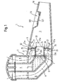
- FIG. 1 shows an embodiment of an inhalation therapy device 1 according to the invention, which has an aerosol membrane generator 2 and a mixing chamber 3.
- the two components are designed as separate units, which are connected together in a suitable manner, so that both components can be safely handled together as a functional unit.
- the aerosol generator 2 of the embodiment FIG. 1 comprises a liquid reservoir 4, in which a medicament-containing liquid 5 can be filled, and a membrane 6, which closes the liquid reservoir 4 at an open surface.
- the membrane 6 is connected on one side to the liquid container 4 in such a way that the liquid 5 filled in the liquid storage container contacts the one side of the membrane 6.
- a vibration generator 7, for example, a piezoelectric element, arranged by the Membrane 6 is vibrated when the vibration generator 7 is driven.
- diaphragm 6 and vibration generator 7 are designed rotationally symmetrically so that vibration generator 7 concentrically surrounds the diaphragm.
- the membrane 6 If the vibration generator 7 is excited, that is, for example, the piezoelectric element is subjected to an alternating voltage, the membrane 6 is set in vibration, so that the liquid filled in the liquid reservoir and pending on the diaphragm 6 liquid 5 through openings in the membrane through to the other side the membrane 6 is promoted and atomized there to form an aerosol.
- the aerosol is discharged into the mixing chamber 3 inside.
- a mouthpiece 10 is furthermore provided, which in the example shown is formed integrally with the mixing chamber 3, but which in a modified embodiment can also be made separable from the mixing chamber 3.
- the patient inhales the aerosol generated by the aerosol membrane generator 2 and discharged into the mixing chamber 3 as it breathes through the mouthpiece.
- the inhalation valve 20 for controlling / checking the supply air Inhalation valve 20 is provided, which allows in Einatemphasen the flow of ambient air into the mixing chamber, but which prevents in exhalation; that the exhaled breathing air passes out of the mixing chamber to the aerosol membrane generator 2.
- the inhalation valve 20 according to the invention prevents the aerosol from being transported with the breathing air from the mixing chamber in exhalation phases and that breathing air flows into the aerosol membrane generator 2.
- the aerosol generator 2 the area around the liquid container 4 around, in which often other components, such as electrical connections for the control of the piezoelectric crystal are protected from breathing air and thus from impurities that get into the therapy device with the breathing air can.
- the inhalation valve 20 according to the invention protects the interior of the aerosol generator 2 during the exhalation phases by closing the mixing chamber 3 to the aerosol membrane generator 2.
- the exhaled air is otherwise directed out of the mixing chamber 3 or mouthpiece 10, for example via a per se known mouthpiece valve 32 which includes a mouthpiece valve opening 321 and a mouthpiece valve element 322. On the operation of the mouthpiece valve will not be discussed here.
- the inhalation valve 20, as in FIG. 1 shown a wall portion of the mixing chamber 3, in which it closes an open wall region of the mixing chamber 3 closes. At the in FIG. 1 In the embodiment shown, the inhalation valve 20 is clamped between the aerosol membrane generator 2 and the mixing chamber 3.
- the inhalation valve 20 includes an aerosol passage 22 that allows the aerosol to move from the membrane into the mixing chamber reach.
- the inhalation valve 20 includes one or more breathing air passage openings 23 through which incoming air enters the mixing chamber in the inhalation phases and which are closed in the exhalation phases.
- the inhalation valve 20 has one or more valve elements 21. This basic structure will be described below with reference to the embodiment according to FIG. 1 explained in more detail by way of example.
- the inhalation valve 20 comprises a cylindrical sleeve 22, which constitutes the aerosol passage through which the aerosol discharged from the membrane flows into the mixing chamber 3.
- the sleeve is aligned with the membrane 6 and preferably arranged concentrically to the membrane 6.
- the sleeve 22 rests with a front side on a surface of the membrane generator 2, which surrounds the membrane 6.
- a sealing of the mixing chamber in the region around the membrane 6 is provided, which prevents breathing air from flowing past the membrane 6 in exhalation phases.
- the aerosol passage 22 for this purpose has a region which is arranged on a surface of the aerosol membrane generator 2, so that the membrane is enclosed along at least one sealing line 20a.
- the aerosol passage 22 of the inhalation valve 20 ensures that, on the one hand, the aerosol can pass from the membrane 6 into the mixing chamber 3 and, on the other hand, a sealing of the mixing chamber 3 takes place in the region of the aerosol membrane generator 2.
- FIG. 1 results in the embodiment shown around the sleeve 22 around a region provided in the breathing air passage openings 23 are provided are.
- the respiratory air passage openings containing area extends substantially perpendicular to the longitudinal axis of the sleeve 22.
- the breathing air passage openings 23 are concentric with the cylindrical sleeve 22 and are formed in the form of circular ring segments, one of which in FIG. 2 is shown.
- Embodiment of the breathing air passage openings 23 is remarkable insofar as the openings, unlike a basic shape in which the breathing air passage openings 23 extend substantially parallel to the aerosol passage 22, are formed obliquely, resulting in a spiral shape.
- This training is in FIG. 2 illustrated by the section along the line AA. Due to the spiral-like oblique design of the breathing air passage openings 23, a breath is imparted to the breathing air which flows through these openings, which causes the breathing air to surround and to some extent enclose the aerosol flowing through the aerosol passage in the mixing chamber. As a result, the risk of impaction of the aerosol particles on the inner wall of the mixing chamber 3 is further reduced.
- FIG. 1 shows in addition to the position in which the valve element 21, the breathing air passage openings 23 closes, the valve element 21a in a raised position in the raised position, ie during Einatemphasen.
- the sleeve 22 in the outer circumferential surface preferably has a circumferential groove 24, in which the inner edge of the annular opening of the valve element 21 is arranged.
- the edge of the ring opening is provided with a thickening 26. This not only ensures a secure mounting of the valve element 21 in the groove 24, but also protects the inner edge of the ring opening against damage when plugging.
- the inhalation valve 20 is arranged between a wall section 31 of the aerosol generator 2 and a wall section 31 of the mixing chamber 3 and is preferably held, for example clamped, in such a way that the inhalation valve 20 is securely fixed and its aerosol passage 22 is positioned precisely.
- the inhalation valve 20 has for this purpose an outer edge portion 25, which is designed for the holder / fixation on the aerosol generator 2 and / or the mixing chamber 3. This is particularly advantageous in FIG. 1 shown embodiment also because the inhalation valve 20 is used to seal the connection point between the aerosol generator 2 and mixing chamber 3.
- the edge portion 25 of the inhalation valve 20 is adapted to the frontal cross sections of the aerosol generator 2 and the mixing chamber 3.
- FIGS. 3A and 3B show that the adaptation of the edge portion 25 to the cross section of the membrane aerosol generator 2 / the mixing chamber 3 can go very far, but always a transition to the inventive area with the breathing air passage openings 23 can be easily created.
- This type of adaptation ensures that the material of the inhalation valve 20, which is fundamentally suitable for sealing purposes, is also used for sealing the transition between the aerosol generator 2 and the mixing chamber 3.
- the inhalation valve 20 is preferably constructed of only two parts.
- the one part comprises in one piece the sleeve 22, the region of the breathing air passage openings 23, the transition region to the edge portion 25 and the edge portion 25 itself; the other part forms the valve element 21st
- FIGS. 1 and 3A also shows that the membrane-facing end face of the cylindrical sleeve 22 preferably has a circumferential thickening 22a. This reduces the risk of damage to the front end of the sleeve.
- FIG. 3B showing a perspective view of an inhalation valve according to the invention from the side of the mixing chamber 3 forth, the thickening 26 at the inner edge of the annular opening of the valve element 21 is clearly visible.
- FIG. 4 shows a further embodiment of an inhalation valve 20 according to the invention in a representation in which parts of the aerosol membrane generator 2 and the mixing chamber 3 are not reproduced; in this regard is on FIG. 1 directed.
- the reservoir 4 and the liquid 5 can be seen, which adjoins the membrane 6.
- the membrane 6 is provided in this embodiment with a Kalottenabêt 6 a, which bulges towards the mixing chamber 3.
- An attachment portion 6b of the diaphragm 6 serves to attach the diaphragm to a carrier 6c, to which the vibration generator 7, for example the piezoelectric element, is attached.
- the inhalation valve 20 comprises an aerosol passage 22 which allows the aerosol released by the membrane to enter the mixing chamber 3.
- the aerosol passage 22 in this embodiment is essentially a flat funnel-shaped structure.
- the aerosol passage 22 has an area formed on a surface of the aerosol membrane generator 2 according to FIG. 4 a surface of the vibration generator 7, rests and the membrane 6 along a sealing line 20a surrounds. This area of the aerosol passage 22 is preferably provided with a thickening 22a.
- the resulting sealing line 20a and the thickening 22a are preferably rotationally symmetrical.
- one or more breathing air passage openings 23 are formed in a designated area. These openings are covered towards the mixing chamber 3 by a valve element 21, so that the openings are released during the inhalation phases and closed during the Ausatemphasen.
- the details of the valve element 21 correspond to those of the valve element of the previously described embodiment, so that reference may be made at this point to the explanations above.
- a projection 24a is provided, the circular in rotationally symmetrical design of the aerosol passage.
- the circumferential groove 24 is formed, in which the valve element 21, preferably with the thickening 26, is fixed.
- Edge region 25, which serves to hold the inhalation valve 20 by the edge 25 is clamped, for example, between a wall 31 of the aerosol membrane generator 2 and a wall 32 of the mixing chamber 3.
- FIG. 5 shows a modification of the embodiment according to FIG. 4 , on whose description also for FIG. 5 Reference is made. To clarify the modification are in FIG. 5 only those reference numbers are given which are directly related to the modification.
- the breathing air openings 23 formed obliquely outward.
- the breathing air passage openings 23 extend away from the fixed location of the valve element 21 retained in the groove 24.
- the breathing air is guided outward with respect to the aerosol passage 22 and thus to the free end of the lifting section of the valve element 21, which leads to a more favorable flow in the mixing chamber 3 and to a lower triggering force for the valve element 21.
- FIG. 6 shows a modification of the embodiment according to FIG. 4 , on whose description also for FIG. 6 Reference is made. To clarify the modification are in FIG. 6 only such reference numerals are given in the immediate Relationship with the modification.
- the projection 24a with respect to the aerosol passage 22 outside, preferably in the vicinity of the edge region 25, arranged.
- the circumferential groove 24 is formed so as to open to the aerosol passage 22.
- the valve element 21 is supported at an outer edge in the groove 24 and preferably has a thickening 26 at the outer edge.
- the valve element 21 extends with its flexible portion to the aerosol passage 22 and thereby covers the breathing air passage openings 23.
- the operation of the valve element 21 of this embodiment completely corresponds to the previously described embodiments.
- FIG. 7 shows a modification of the embodiment according to FIG. 6 , on whose description also for FIG. 7 Reference is made. To clarify the modification are in FIG. 7 only those reference numbers are given which are directly related to the modification.
- the breathing air openings 23 are formed running obliquely inwards.
- the breathing air passage openings 23 extend away from the fixed location of the valve element 21 retained in the groove 24.
- the breathing air is directed inwards with respect to the aerosol passage 22 and thus to the free end of the lifting section of the valve element 21, which leads to a more favorable flow in the mixing chamber 3 and to a lower triggering force for the valve element 21.
- FIG. 8 shows a further embodiment of an inhalation valve 20 according to the invention in a representation in which parts of the aerosol membrane generator 2 and the mixing chamber 3 are not reproduced; in this regard is on FIG. 1 directed.
- the aerosol passage 22 is formed very flat; the region with the breathing air passage openings 23 is arranged substantially in a plane to the membrane 6 of the aerosol membrane generator 2.
- the aerosol passage 22 of this inhalation valve 20 also has an area which rests on a surface of the aerosol membrane generator 2 and surrounds the membrane along at least one sealing line 20a, thereby ensuring the sealing of the mixing chamber around the membrane.
- the valve element 21 is designed and arranged such that it closes the breathing air passage openings 23 during the exhalation phases and releases them during the inhalation phases.
- a transition region 22b is formed, in which preferably the circumferential groove 24 is provided.
- the breathing air passage openings 23 can also in this embodiment, based on the Figures 5 and 7 according to the fixing point of the valve element 21 to the outside or inward obliquely and in accordance with FIG. 2 be formed spirally.
Description
Die Erfindung betrifft eine Inhalationstherapievorrichtung mit einem Aerosolmembrangenerator und einer Mischkammer sowie einem Einatemventil.The invention relates to an inhalation therapy device with an aerosol membrane generator and a mixing chamber and an inhalation valve.
Mit Inhalationstherapievorrichtungen dieser Art können medikamenthaltige Flüssigkeiten, flüssige Medikamente oder andere therapeutisch einsetzbare Flüssigkeiten, beispielsweise Salzlösungen, vernebelt werden, um dem Patienten ein Aerosol für die Inhalation darzubieten.With inhalation therapy devices of this type, medicament-containing fluids, liquid medicaments or other therapeutically employable fluids, for example saline solutions, can be aerosolized to provide the patient with an aerosol for inhalation.
Wenn bei dem bekannten Therapievernebler der Patient in die Vorrichtung hinein ausatmet, gelangt zwar ein großer Teil der Atemluft über ein in einem Mundstück der Vorrichtung vorgesehenes Ausatemventil unmittelbar in Umgebung, jedoch sind auch der Aerosolmembrangenerator und der Bereich des Flüssigkeitsvorratsbehälters einem Teil der Atemluft ausgesetzt. Es kommt auf diese Weise zu unerwünschten Verunreinigungen des Aerosolgenerators.While in the known therapy nebulizer the patient exhales into the device, a large portion of the breathing air passes directly through an exhalation valve provided in a mouthpiece of the device, but also the aerosol membrane generator and the area of the fluid reservoir are exposed to a portion of the breathing air. It comes in this way to unwanted impurities of the aerosol generator.
Das von der Erfindung zu lösende Problem besteht vor dem Hintergrund dieses Standes der Technik darin, eine Inhalationstherapievorrichtung anzugeben, bei der das Einatemventil derart gestaltet ist, dass das Risiko einer Verunreinigung des Aerosolmembrangenerators durch die Atemluft des Patienten während der Ausatemphasen verringert ist.The problem to be solved by the invention in view of this prior art is to provide an inhalation therapy device in which the inhalation valve is designed such that the risk of contamination of the aerosol membrane generator by the respiratory air of the patient during the exhalation phases is reduced.
Dieses Problem wird erfindungsgemäß gelöst durch eine Inhalationstherapievorrichtung mit einem Aerosolmembrangenerator, mit einem Flüssigkeitsvorratsbehälter, in den eine therapeutisch einsetzbare Flüssigkeit einfüllbar ist, mit einer Membran, die auf einer Seite mit dem Flüssigkeitsbehälter derart in Verbindung steht, dass eine in den Flüssigkeitsvorratsbehälter eingefüllte Flüssigkeit in Berührung mit einer Seite der Membran gelangt, und mit einem Schwingungsgenerator für die Erzeugung von Schwingungen, durch die eine in den Flüssigkeitsvorratsbehälter eingefüllte Flüssigkeit durch Öffnungen der Membran hindurch auf der anderen Seite der Membran zu einem Aerosol zerstäubt wird. Ferner weist die erfindungsgemäße Inhalationstherapievorrichtung eine Mischkammer, in die hinein der Aerosolmembrangenerator das Aerosol erzeugt, und ein Einatemventil auf, das in Einatemphasen den Zustrom von Umgebungsluft in die Mischkammer zulässt und in Ausatemphasen das Austreten des Aerosols aus der Mischkammer verhindert und das einen Wandabschnitt der Mischkammer bildet. Das Einatemventil wiederum umfasst einen Aerosoldurchlass, durch den das von dem Membrangenerator erzeugte Aerosol in die Mischkammer gelangt, der mit einem Abschnitt auf einer Oberfläche des Aerosolmembrangenerators die Membran längs zumindest einer Dichtlinie umschließend angeordnet ist und der sich in die Mischkammer hinein öffnend erstreckt, zumindest eine Atemluftdurchtrittsöffnung, die in einem Bereich um den Aerosoldurchlass angeordnet ist, und ein Ventilelement, das im Bereich um den Aerosoldurchlass derart angeordnet ist, dass das Ventilelement die zumindest eine Atemluftdurchtrittsöffnung in Ausatemphasen verschließt und in Einatemphasen freigibt.This problem is solved according to the invention by an inhalation therapy device with an aerosol membrane generator, with a liquid reservoir into which a therapeutically usable liquid can be filled, with a membrane which is connected on one side to the liquid container in such a way that a liquid filled in the liquid reservoir in contact comes with one side of the membrane, and with a vibration generator for the Generation of vibrations by which a liquid filled in the liquid reservoir is atomized through openings in the membrane on the other side of the membrane into an aerosol. Furthermore, the inhalation therapy device according to the invention comprises a mixing chamber into which the aerosol membrane generator generates the aerosol, and an inhalation valve which permits the inflow of ambient air into the mixing chamber in inspiration phases and prevents the aerosol from escaping from the mixing chamber in exhalation phases and the one wall section of the mixing chamber forms. The inhalation valve in turn comprises an aerosol passage through which the aerosol generated by the membrane generator passes into the mixing chamber, which is arranged with a portion on a surface of the aerosol membrane generator surrounding the membrane along at least one sealing line and which extends into the mixing chamber, at least one opening Breathing air passage opening, which is arranged in a region around the aerosol passage, and a valve element, which is arranged in the region around the aerosol passage such that the valve element closes the at least one breathing air passage in exhalation phases and releases in inhalation phases.
Durch die räumlich benachbarte Anordnung des Aerosoldurchlasses, der Atemluftdurchtrittsöffnung und des Ventilelements wird ein Einatemventil geschaffen, das sich als Wandabschnitt der Mischkammer eignet und dadurch vor dem Membranvernebler angeordnet werden kann. Die außerhalb der Mischkammer liegenden Teile der Gesamtvorrichtung sind deshalb besser vor Verunreinigungen geschützt. Der Aerosoldurchlass stellt nicht nur sicher, dass eine Abdichtung der Mischkammer im Bereich um die Membran herum erfolgt, sondern unterstützt auch wirksam die Ausbreitung des Aerosols von der Membran in die Mischkammer hinein. Dabei ist vorteilhaft, dass durch den Aerosoldurchlass eine zuverlässige Abdichtung an der Oberfläche des Aerosolgenerators um die Membran herum gewährleistet werden kann. Ferner wird bei dem erfindungsgemäßen Inhalationstherapiegerät die Atemluft bezogen auf den Aerosoldurchlass außen geführt und schirmt dadurch das durch den Aerosoldurchlass in die Mischkammer eintretende Aerosol gewissermaßen ab, so dass eine unerwünschte Impaktion der Aerosolpartikel bzw. -tröpfchen an der Wand der Mischkammer verringert wird.The spatially adjacent arrangement of the aerosol passage, the breathing air passage opening and the valve element, an inhalation valve is provided which is suitable as a wall portion of the mixing chamber and thereby can be arranged in front of the membrane nebulizer. The lying outside the mixing chamber parts of the overall device are therefore better protected against contamination. Not only does the aerosol passage ensure that the mixing chamber is sealed in the area around the membrane, but it also effectively aids in the propagation of the aerosol from the membrane into the mixing chamber. It is advantageous that by the Aerosol passage a reliable seal on the surface of the aerosol generator can be ensured around the membrane. Furthermore, in the inhalation therapy device according to the invention, the breathing air is guided externally with respect to the aerosol passage and thereby effectively shields the aerosol entering the mixing chamber through the aerosol passage, so that an undesired impaction of the aerosol particles or droplets on the wall of the mixing chamber is reduced.
Vorzugsweise sind mehrere Atemlufdurchtrittsöffnungen vorhanden, die von dem einen oder von mehreren getrennten oder miteinander verbundenen Ventilelementen verschlossen bzw. freigegeben werden.Preferably, a plurality of breathing air passage openings are provided, which are closed or released by the one or more separate or interconnected valve elements.
Für die einfache Halterung des Ventilelements ist eine umlaufende Nut vorgesehen.For the simple mounting of the valve element, a circumferential groove is provided.
Um das Risiko von Beschädigungen zu verringern und die Halterung zu verbessern, weist das Ventilelement am Rand für die Halterung in der umlaufenden Nut eine Verdickung auf.To reduce the risk of damage and to improve the holder, the valve element at the edge for holding in the circumferential groove on a thickening.
In einer bevorzugten Ausgestaltung ist der Aerosoldurchlass rohrartig und das Ventilelement ringförmig ausgebildet. Das Ventilelement nimmt dann den rohrartige Aerosoldurchlass in der Ringöffnung auf. Vorzugsweise ist in diesem Fall die umlaufende Nut für die Aufnahme des Ventilelements in der äußeren Mantelfläche des rohrartigen Aerosoldurchlasses vorgesehen.In a preferred embodiment, the aerosol passage is tube-like and the valve element is annular. The valve element then receives the tubular aerosol passage in the ring opening. Preferably, in this case, the circumferential groove for receiving the valve element in the outer circumferential surface of the tubular aerosol passage is provided.
In einer bevorzugten Ausgestaltung wird der rohrartige Aerosoldurchlass durch eine zylindrische Hülse gebildet, an deren Mantelfläche ein die Atemluftdurchtrittsöffnungen aufnehmender Bereich vorgesehen ist, der sich im wesentlichen senkrecht zur Längsachse der Hülse erstreckt. Vorzugsweise ist die Hülse konzentrisch zu der Membran angeordnet. In Anpassung an diese Gestaltung ist das Ventilelement kreisringförmig ausgebildet und nimmt die zylindrische Hülse in der Ringöffnung auf. Entsprechend weist das ringförmige Ventilelement am Rand der Ringöffnung für die Halterung an der zylindrischen Hülse eine Verdickung auf. Zur Fixierung ist vorteilhafterweise die umlaufende Nut für die Aufnahme des Randes der Ringöffnung des Ventilelements in der Mantelfläche der zylindrischen Hülse vorgesehen.In a preferred embodiment, the tubular aerosol passage is formed by a cylindrical sleeve, on whose lateral surface a the breathing air passage openings receiving area is provided which extends substantially perpendicular to the longitudinal axis of the sleeve. Preferably, the sleeve is arranged concentrically with the membrane. In adaptation to this design, the valve element is annular and receives the cylindrical sleeve in the ring opening. Accordingly, the annular valve element at the edge of the annular opening for the support on the cylindrical sleeve on a thickening. For fixing the circumferential groove for receiving the edge of the annular opening of the valve element is advantageously provided in the lateral surface of the cylindrical sleeve.
Um Beschädigungen zu vermeiden und die Abdichtung der Mischkammer im Bereich der Membran zu unterstützen, weist der Aerosoldurchlass in dem der Oberfläche des Aerosolmembrangenerators zugewandten Bereich eine Verdickung auf.In order to avoid damage and to support the sealing of the mixing chamber in the region of the membrane, the aerosol passage in the region facing the surface of the aerosol membrane generator has a thickening.
In einer Grundform erstrecken sich die Atemluftdurchtrittsöffnungen im wesentlichen parallel zu dem Aerosoldurchlass. In einer vorteilhaften Gestaltung verlaufen die Atemluftdurchtrittsöffnungen jedoch spiralartig, um der durch die Öffnungen strömenden Luft einen Drall aufzuprägen.In a basic form, the breathing air passages extend substantially parallel to the aerosol passage. In an advantageous embodiment, however, the breathing air passage openings extend in a spiral manner in order to impart a twist to the air flowing through the openings.
Grundsätzlich ist eine Gestaltung zu bevorzugen, bei der die Atemluftdurchtrittsöffnungen als Kreisringabschnitte gebildet werden.Basically, a design is to be preferred in which the breathing air passage openings are formed as circular ring sections.
Das Einatemventil ist insgesamt vorzugsweise mit einem Randabschnitt ausgestaltet, der für die Halterung des Einatemventils, insbesondere für das Einklemmen zwischen Aerosolgenerator und Mischkammer ausgestaltet ist.Overall, the inhalation valve is preferably configured with an edge section which is configured for holding the inhalation valve, in particular for clamping between the aerosol generator and the mixing chamber.
Vorzugsweise sind die Atemluftdurchtrittsöffnungen derart schräg verlaufend ausgestaltet, dass die Atemluft von der Fixierungsstelle des Ventilelements weg geführt wird. Dadurch wird die Auslösung des Ventils zu Beginn der Einatemphasen unterstützt und eine verbesserte Strömungsführung unterstützt, die zu geringen Depositionsraten insbesondere an den Mischkammerwänden führt.Preferably, the breathing air passage openings are such designed to extend obliquely, that the breathing air is guided away from the fixation point of the valve element. This supports the triggering of the valve at the beginning of the inhalation phases and supports improved flow guidance, which leads to low deposition rates, in particular at the mixing chamber walls.
Geringere Depositionsraten werden auch durch eine Gestaltung erzielt, bei der die Atemluftdurchtrittsöffnungen allseitig um den Aerosoldurchlass herum vorgesehen sind.Lower deposition rates are also achieved by a design in which the breathing air passage openings are provided on all sides around the aerosol passage.
In einer speziellen Ausgestaltung ist der Bereich der Atemluftdurchtrittsöffnungen im wesentlichen in einer Ebene mit der Membran angeordnet.In a specific embodiment, the region of the breathing air passage openings is arranged substantially in a plane with the membrane.
Bevorzugt ist das Ventilelement aus einem elastischen Material hergestellt. Auch das Einatemventil ist vorzugsweise aus einem elastischen Material hergestellt.Preferably, the valve element is made of an elastic material. Also, the inhalation valve is preferably made of an elastic material.
Die Erfindung wird im Folgenden anhand eines Ausführungsbeispiels und unter Bezugnahme auf die Zeichnungen genauer erläutert. In den Zeichnungen zeigt:
- Fig. 1
- eine geschnittene Ansicht eines Ausführungsbeispiels einer erfindungsgemäßen Inhalationsvorrichtung;
- Fig. 2
- in einer Ausschnittsansicht den Bereich der Atemluftdurchtrittsöffnungen mit spiralartig ausgebildeten Öffnungen;
- Fig. 3A und 3B
- perspektivische Ansichten eines erfindungsgemäßen Einatemventils;
- Fig. 4
- ein weiteres Ausführungsbeispiel einer erfindungsgemäßen Inhalationsvorrichtung;
- Fig. 5
- eine Abwandlung des Ausführungsbeispiels gemäß
Figur 4 - Fig. 6
- ein weiteres Ausführungsbeispiel einer erfindungsgemäßen Inhalationsvorrichtung;
- Fig. 7
- eine Abwandlung des Ausführungsbeispiels gemäß
Figur 6 ; und - Fig. 8
- ein weiteres Ausführungsbeispiel einer erfindungsgemäßen Inhalationsvorrichtung.
- Fig. 1
- a sectional view of an embodiment of an inhalation device according to the invention;
- Fig. 2
- in a sectional view of the region of the breathing air openings with spirally formed openings;
- FIGS. 3A and 3B
- perspective views of an inhalation valve according to the invention;
- Fig. 4
- a further embodiment of an inhalation device according to the invention;
- Fig. 5
- a modification of the embodiment according to
FIG. 4 ; - Fig. 6
- a further embodiment of an inhalation device according to the invention;
- Fig. 7
- a modification of the embodiment according to
FIG. 6 ; and - Fig. 8
- a further embodiment of an inhalation device according to the invention.
Die
Der Aerosolgenerator 2 des Ausführungsbeispiels aus
Wird der Schwingungsgenerator 7 angeregt, also beispielsweise das Piezo-Element mit einer Wechselspannung beaufschlagt, wird die Membran 6 in Schwingungen versetzt, so dass die in den Flüssigkeitsvorratsbehälter eingefüllte und an der Membran 6 anstehende Flüssigkeit 5 durch Öffnungen in der Membran hindurch auf die andere Seite der Membran 6 gefördert und dort zu einem Aerosol zerstäubt wird. Das Aerosol wird in die Mischkammer 3 hinein abgegeben.If the vibration generator 7 is excited, that is, for example, the piezoelectric element is subjected to an alternating voltage, the membrane 6 is set in vibration, so that the liquid filled in the liquid reservoir and pending on the diaphragm 6 liquid 5 through openings in the membrane through to the other side the membrane 6 is promoted and atomized there to form an aerosol. The aerosol is discharged into the mixing
Bei dem in
Während der Einatemphase strömt Umgebungsluft durch Zuluftkanäle 8, die in dem Aerosolmembrangenerator 2 ausgebildet sind, in das Therapiegerät und gelangt in die Mischkammer 3; der Strömungsverlauf der Zuluft ist in
Erfindungsgemäß ist zur Steuerung/Kontrolle der Zuluft ein Einatemventil 20 vorgesehen, das in Einatemphasen den Zustrom von Umgebungsluft in die Mischkammer zulässt, das aber in Ausatemphasen verhindert; dass die ausgeatmete Atemluft aus der Mischkammer heraus zu dem Aerosolmembrangenerator 2 gelangt. Damit verhindert das erfindungsgemäße Einatemventil 20, dass in Ausatemphasen das Aerosol mit der Atemluft aus der Mischkammer transportiert wird und dass Atemluft in den Aerosolmembrangenerator 2 strömt. Dadurch wird in dem Aerosolgenerator 2 der Bereich um den Flüssigkeitsbehälter 4 herum, in dem sich oftmals auch andere Komponenten, beispielsweise elektrische Anschlüsse für die Ansteuerung des Piezo-Kristalls befinden, vor Atemluft und damit vor Verunreinigungen geschützt, die mit der Atemluft in das Therapiegerät gelangen können. Somit schützt das erfindungsgemäße Einatemventil 20 das Innere des Aerosolgenerators 2 während der Ausatemphasen, indem es die Mischkammer 3 zum Aerosolmembrangenerator 2 hin verschließt.According to the invention for controlling / checking the supply
Die Ausatemluft wird auf andere Weise aus der Mischkammer 3 bzw. dem Mundstück 10 geführt, beispielsweise über ein an sich bekanntes Mundstückventil 32, das eine Mundstückventilöffnung 321 und ein Mundstückventilelement 322 umfasst. Auf die Funktionsweise des Mundstückventils wird hier aber nicht näher eingegangen.The exhaled air is otherwise directed out of the mixing
Erfindungsgemäß bildet das Einatemventil 20, wie in
Das Einatemventil 20 umfasst einen Aerosoldurchlass 22, der es dem Aerosol gestattet, von der Membran in die Mischkammer zu gelangen. Außerdem umfasst das Einatemventil 20 eine oder mehrere Atemluftdurchtrittsöffnungen 23, durch die in den Eintatemphasen Zuluft in die Mischkammer gelangt und die in den Ausatemphasen verschlossen sind. Dazu besitzt das Einatemventil 20 ein oder mehrere Ventilelemente 21. Dieser grundsätzliche Aufbau wird im folgenden anhand des Ausführungsbeispiels gemäß
Bei dem gezeigten Ausführungsbeispiel umfasst das Einatemventil 20 eine zylindrische Hülse 22, die den Aerosoldurchlass darstellt, durch den das von der Membran abgegebene Aerosol in die Mischkammer 3 strömt. Die Hülse ist an der Membran 6 ausgerichtet und vorzugsweise konzentrisch zur Membran 6 angeordnet. Die Hülse 22 liegt mit einer Stirnseite auf einer Oberfläche des Membrangenerators 2 auf, die die Membran 6 umgibt. Dadurch wird eine Abdichtung der Mischkammer im Bereich um die Membran 6 herum geschaffen, die verhindert, dass in Ausatemphasen Atemluft an der Membran 6 vorbei strömt.In the embodiment shown, the
Grundsätzlich betrachtet weist der Aerosoldurchlass 22 zu diesem Zweck einen Bereich auf, der auf einer Oberfläche des Aerosolmembrangenerators 2 angeordnet ist, so dass die Membran längs zumindest einer Dichtlinie 20a umschlossen ist. Auf diese Weise stellt der Aerosoldurchlass 22 des Einatemventils 20 sicher, dass einerseits das Aerosol von der Membran 6 in die Mischkammer 3 gelangen kann und dass andererseits eine Abdichtung der Mischkammer 3 im Bereich des Aerosolmembrangenerators 2 erfolgt.Viewed in principle, the
Wie sich aus den
Die in
Auf der der Mischkammer zugewandten Seite des Bereichs der Atemluftdurchtrittsöffnungen 23 ist ein Ventilelement 21 angeordnet, das bei dem gezeigten Ausführungsbeispiel kreisringförmig und flach ist und das die zylindrische Hülse 22 in seiner zentrischen Ringöffnung aufnimmt.
Zur Halterung des Ventilelements 21 weist die Hülse 22 in der äußeren Mantelfläche vorzugsweise eine umlaufende Nut 24 auf, in der der innere Rand der Ringöffnung des Ventilelements 21 angeordnet ist. Der Rand der Ringöffnung ist dabei mit einer Verdickung 26 versehen. Dadurch wird nicht nur eine sichere Halterung des Ventilelements 21 in der Nut 24 gewährleistet, sondern auch der innere Rand der Ringöffnung gegen Beschädigungen beim Aufstecken geschützt.For holding the
Bei dem in
Die
Daraus ergibt sich ferner, dass das erfindungsgemäße Einatemventil 20 vorzugsweise nur aus zwei Teilen aufgebaut ist. Denn der eine Teil umfasst in einem Stück die Hülse 22, den Bereich der Atemluftdurchtrittsöffnungen 23, den Übergangsbereich zum Randabschnitt 25 und den Randabschnitt 25 selbst; den anderen Teil bildet das Ventilelement 21.It also follows that the
Aus den
Das erfindungsgemäße Einatemventil 20 dieses Ausführungsbeispiels umfasst einen Aerosoldurchlass 22, der es dem von der Membran abgegebenen Aerosol gestattet, in die Mischkammer 3 -zu gelangen. Der Aerosoldurch-lass 22 ist bei diesem Ausführungsbeispiel im wesentlichen ein flaches trichterförmiges Gebilde. Der Aerosoldurchlass 22 weist einen Bereich auf, der auf einer Oberfläche des Aerosolmembrangenerators 2, gemäß
Bei dem Aerosoldurchlass 22 sind eine oder mehrere Atemluftdurchtrittsöffnungen 23 in einem dafür vorgesehenen Bereich ausgebildet. Diese Öffnungen werden zur Mischkammer 3 hin von einem Ventilelement 21 abgedeckt, so dass die Öffnungen während der Einatemphasen freigegeben und während der Ausatemphasen verschlossen sind. Die Einzelheiten des Ventilelements 21 entsprechen denen des Ventilelements des zuvor geschilderten Ausführungsbeispiels, so dass an dieser Stelle auf die Erläuterungen oben verwiesen werden kann.In the
Zur sicheren Halterung ist an dem Aerosoldurchlass 22 gemäß
Auch bei dem Ausführungsbeispiel gemäß
Abweichend von dem Ausführungsbeispiel gemäß
Zusätzlich zu der in
Abweichend von dem Ausführungsbeispiel gemäß
Abweichend von dem Ausführungsbeispiel gemäß
Zusätzlich zu der in
Claims (19)
- Inhalation therapy device havinga. an aerosol membrane generator (2)i. having a liquid storage container (4) into which a liquid (5) usable for therapy can be charged,ii. having a membrane (6) connected on one side to the liquid container (4) in such a way that a liquid (5) charged into the liquid storage container comes into contact with one side of the membrane (6), andiii. having a vibration generator (7) for generating vibrations by means of which a liquid (5) charged into the liquid storage container is atomised to form an aerosol on the other side of the membrane through openings in the membrane (6),b. a mixing chamber (3) into which the aerosol membrane generator (2) generates the aerosol, andc. an inhalation valve (20, 21) which in inhalation phases allows the flow of ambient air into the mixing chamber (3) and in exhalation phases prevents the escape of the aerosol from the mixing chamber (3) and which forms a wall section of the mixing chamber (3), characterised byi. an aerosol outlet (22) through which the aerosol generated by the membrane generator comes into the mixing chamber (3), which is arranged by a section on a surface of the aerosol membrane generator (2) enclosing the membrane (3) along at least one sealing line (20a) and which extends opening into the mixing chamber,ii. at least one inhaled air passage opening (23) arranged in the region of the aerosol outlet (22), andiii. a valve element (21) arranged in the region around the aerosol outlet (22) in such a way that the valve element (21) seals the at least single inhaled air passage opening (23) in exhalation phases and releases it in inhalation phases.
- Inhalation therapy device according to claim 1, characterised in that a plurality of inhaled air passage openings (23) is provided.
- Inhalation therapy device according to claim 1 or 2, characterised in that an all-round groove (24) is provided for mounting the valve element (21).
- Inhalation therapy device according to claim 3, characterised in that for mounting in the all-round groove (24) the valve element (21) comprises a bulge (26).
- Inhalation therapy device according to any of claims 1 to 4, characterised in that the aerosol outlet (22) is of tubular construction and the valve element (21) of annular construction and the valve element (21) accommodates the tubular aerosol outlet (22) in the annular opening.
- Inhalation therapy device according to claim 5, characterised in that the all-round groove (24) is provided for accommodating the valve element (21) in the outer jacket surface of the tubular aerosol outlet (22).
- Inhalation therapy device according to one of claims 5 or 6, characterised in that the tubular aerosol outlet is formed by a cylindrical sleeve (22) on whose outer jacket surface a region accommodating the inhaled air passage openings (23) is provided which extends substantially perpendicular to the longitudinal axis of the sleeve.
- Inhalation therapy device according to claim 7, characterised in that the cylindrical sleeve (22) is arranged concentrically with respect to the membrane (6).
- Inhalation therapy device according to one of claims 7 or 8, characterised in that the valve element (21) is of annular construction and accommodates the cylindrical sleeve (22) in the annular opening.
- Inhalation therapy device according to any of the preceding claims, characterised in that the aerosol outlet (22) in the region facing towards the membrane has a bulge (22a).
- Inhalation therapy device according to any of the preceding claims, characterised in that the single or several inhaled air passage openings (23) extend substantially parallel to the aerosol outlet (22).
- Inhalation therapy device according to any of the preceding claims 1 to 9, characterised in that the single or several inhaled air passage openings (23) run in the shape of a spiral with respect to the aerosol outlet (22).
- Inhalation therapy device according to any of the preceding claims, characterised in that the single or several inhaled air passage openings (23) are formed as circular sections or segments.
- Inhalation therapy device according to any of the preceding claims, characterised in that the inhalation valve (20) has a peripheral section (25) which is designed for fixing the inhalation valve (20), in particular for clamping it between a wall (31) of the aerosol generator (2) and a wall (32) of the mixing chamber (3).
- Inhalation therapy device according to any of the preceding claims, characterised in that the single or several inhaled air passage openings (23) are provided on all sides around the aerosol outlet (22).
- Inhalation therapy device according to any of the preceding claims, characterised in that the inhaled air passage openings (23) are designed to run obliquely in such a way that the inhaled air is carried away from the fixing point of the valve element (21).
- Inhalation therapy device according to any of the preceding claims, characterised in that the region of the single or several inhaled air passage openings (23) is arranged substantially in a plane with the membrane (6).
- Inhalation therapy device according to any of the preceding claims, characterised in that the valve element (21) is manufactured from an elastic material.
- Inhalation therapy device according to any of the preceding claims, characterised in that the inhalation valve (20) is manufactured from an elastic material.
Applications Claiming Priority (3)
| Application Number | Priority Date | Filing Date | Title |
|---|---|---|---|
| DE10257381 | 2002-12-09 | ||
| DE10257381A DE10257381B4 (en) | 2002-12-09 | 2002-12-09 | Inhalation therapy device |
| PCT/EP2003/013959 WO2004052436A1 (en) | 2002-12-09 | 2003-12-09 | Inhalation therapy device |
Publications (2)
| Publication Number | Publication Date |
|---|---|
| EP1569710A1 EP1569710A1 (en) | 2005-09-07 |
| EP1569710B1 true EP1569710B1 (en) | 2009-05-27 |
Family
ID=32477466
Family Applications (1)
| Application Number | Title | Priority Date | Filing Date |
|---|---|---|---|
| EP03782349A Expired - Lifetime EP1569710B1 (en) | 2002-12-09 | 2003-12-09 | Inhalation therapy device |
Country Status (5)
| Country | Link |
|---|---|
| US (1) | US9061303B2 (en) |
| EP (1) | EP1569710B1 (en) |
| AU (1) | AU2003289997A1 (en) |
| DE (2) | DE10257381B4 (en) |
| WO (1) | WO2004052436A1 (en) |
Cited By (1)
| Publication number | Priority date | Publication date | Assignee | Title |
|---|---|---|---|---|
| US9179691B2 (en) | 2007-12-14 | 2015-11-10 | Aerodesigns, Inc. | Delivering aerosolizable food products |
Families Citing this family (36)
| Publication number | Priority date | Publication date | Assignee | Title |
|---|---|---|---|---|
| UA94711C2 (en) * | 2005-05-25 | 2011-06-10 | Аэроджен, Инк. | Vibration systems and methods of making a vibration system, methods of vibrating a plate, aerosol generating system and method of treating a patient |
| ES2594368T3 (en) | 2005-12-08 | 2016-12-19 | Insmed Incorporated | Lipid-based compositions of anti-infectives to treat lung infections |
| EP2740487B1 (en) * | 2006-02-09 | 2018-02-28 | Kamada Ltd. | Alpha-i antitrypsin for treating exacerbation episodes of pulmonary diseases |
| EP1927373B1 (en) * | 2006-11-30 | 2012-08-22 | PARI Pharma GmbH | Inhalation nebulizer |
| US9119783B2 (en) | 2007-05-07 | 2015-09-01 | Insmed Incorporated | Method of treating pulmonary disorders with liposomal amikacin formulations |
| EP2077132A1 (en) | 2008-01-02 | 2009-07-08 | Boehringer Ingelheim Pharma GmbH & Co. KG | Dispensing device, storage device and method for dispensing a formulation |
| JP5553520B2 (en) * | 2008-03-31 | 2014-07-16 | キヤノン株式会社 | Inhaler |
| DE102008022987A1 (en) * | 2008-05-09 | 2009-11-12 | Pari Pharma Gmbh | Nebulizer for respirators and ventilator with such a nebulizer |
| EP2414560B1 (en) | 2009-03-31 | 2013-10-23 | Boehringer Ingelheim International GmbH | Method for coating a surface of a component |
| EP2432531B1 (en) * | 2009-05-18 | 2019-03-06 | Boehringer Ingelheim International GmbH | Adapter, inhalation device and nebulizer |
| US10016568B2 (en) | 2009-11-25 | 2018-07-10 | Boehringer Ingelheim International Gmbh | Nebulizer |
| JP5658268B2 (en) | 2009-11-25 | 2015-01-21 | ベーリンガー インゲルハイム インターナショナル ゲゼルシャフト ミット ベシュレンクテル ハフツング | Nebulizer |
| US9943654B2 (en) | 2010-06-24 | 2018-04-17 | Boehringer Ingelheim International Gmbh | Nebulizer |
| EP2457609A1 (en) * | 2010-11-24 | 2012-05-30 | PARI Pharma GmbH | Aerosol generator |
| US9827384B2 (en) | 2011-05-23 | 2017-11-28 | Boehringer Ingelheim International Gmbh | Nebulizer |
| WO2013152894A1 (en) | 2012-04-13 | 2013-10-17 | Boehringer Ingelheim International Gmbh | Atomiser with coding means |
| JP6402097B2 (en) | 2012-05-21 | 2018-10-10 | インスメッド インコーポレイテッド | System for treating pulmonary infections |
| EP2708219A1 (en) * | 2012-09-12 | 2014-03-19 | PARI Pharma GmbH | Opening element for opening an ampoule in an aerosol generation device and aerosol generation device comprising the opening element |
| CN104755088A (en) | 2012-10-31 | 2015-07-01 | 格莱克特生物技术公司 | Galactoside inhibitor of galectin-3 and its use for treating pulmonary fibrosis |
| US10124066B2 (en) | 2012-11-29 | 2018-11-13 | Insmed Incorporated | Stabilized vancomycin formulations |
| ES2836977T3 (en) | 2013-08-09 | 2021-06-28 | Boehringer Ingelheim Int | Nebulizer |
| US9937302B2 (en) | 2013-09-13 | 2018-04-10 | Delta Electronics, Inc. | Nebulizing device and nebulizer |
| TWI539978B (en) * | 2013-09-13 | 2016-07-01 | 台達電子工業股份有限公司 | Nebulizer and medicament storage module thereof |
| PT3142643T (en) | 2014-05-15 | 2019-10-28 | Insmed Inc | Methods for treating pulmonary non-tuberculous mycobacterial infections |
| EP2957349A1 (en) * | 2014-06-20 | 2015-12-23 | PARI Pharma GmbH | Aerosol generator and aerosol delivery device comprising the aerosol generator |
| DE102014215064A1 (en) | 2014-07-31 | 2016-02-04 | Pari GmbH Spezialisten für effektive Inhalation | nebulizer |
| EP3103497B1 (en) * | 2015-06-11 | 2019-04-24 | Delta Electronics, Inc. | Nebulizing device and nebulizer |
| CN105214183A (en) * | 2015-11-06 | 2016-01-06 | 厦门唯科健康科技有限公司 | Medical vaporizer |
| JP6863984B2 (en) | 2015-12-18 | 2021-04-21 | ガレクト・バイオテック・エイビイ | Crystal polymorphs and processes |
| US10953730B2 (en) * | 2016-11-02 | 2021-03-23 | Christopher A. David | Air scenting system |
| EP3773505A4 (en) | 2018-03-30 | 2021-12-22 | Insmed Incorporated | Methods for continuous manufacture of liposomal drug products |
| US11135379B2 (en) * | 2019-02-15 | 2021-10-05 | Bn Intellectual Properties, Inc. | Method of delivering pharmaceutical products |
| CN111214735A (en) * | 2020-03-20 | 2020-06-02 | 青岛未来移动医疗科技有限公司 | Atomizer mist storage tank |
| EP4125804A1 (en) | 2020-04-01 | 2023-02-08 | UNION therapeutics A/S | Treatment |
| US11045434B1 (en) | 2020-04-01 | 2021-06-29 | UNION therapeutics A/S | Niclosamide formulations for treating disease |
| WO2021198116A1 (en) | 2020-04-01 | 2021-10-07 | UNION therapeutics A/S | Formulation |
Family Cites Families (16)
| Publication number | Priority date | Publication date | Assignee | Title |
|---|---|---|---|---|
| US4113809A (en) * | 1977-04-04 | 1978-09-12 | Champion Spark Plug Company | Hand held ultrasonic nebulizer |
| GB2291605B (en) * | 1991-11-12 | 1996-05-01 | Medix Ltd | A nebuliser and nebuliser control system |
| KR100316439B1 (en) * | 1992-10-16 | 2002-08-09 | 셰이만울트라소닉리서치파운데이션피티와이리미티드 | Ultrasonic Spraying Device |
| GB2272389B (en) | 1992-11-04 | 1996-07-24 | Bespak Plc | Dispensing apparatus |
| US5592935A (en) * | 1995-05-03 | 1997-01-14 | Minnesota Mining And Manufacturing Company | Positive/negative air pressure adaptor for use with respirators |
| US5694920A (en) * | 1996-01-25 | 1997-12-09 | Abrams; Andrew L. | Inhalation device |
| DE19734022C2 (en) * | 1997-08-06 | 2000-06-21 | Pari Gmbh | Inhalation therapy device with a valve to limit the flow of inspiration |
| US6584971B1 (en) * | 1999-01-04 | 2003-07-01 | Medic-Aid Limited | Drug delivery apparatus |
| US6196218B1 (en) * | 1999-02-24 | 2001-03-06 | Ponwell Enterprises Ltd | Piezo inhaler |
| DE19953317C1 (en) | 1999-11-05 | 2001-02-01 | Pari Gmbh | Aerosol generation unit for inhalation therapies, comprises a valve which allows patient's exhaled air to enter into the surroundings, but prevents direct entry of external air into the mixing chamber during the inhaling phase |
| US6412481B1 (en) | 1999-12-23 | 2002-07-02 | Robert Bienvenu | Sealed backpressure attachment device for nebulizer |
| DE10022795B4 (en) | 2000-05-10 | 2005-04-14 | Pari GmbH Spezialisten für effektive Inhalation | Breath-controlled inhalation therapy device |
| US6691703B2 (en) * | 2001-01-31 | 2004-02-17 | Laerdal Medical Corporation | CPR barrier device |
| DE60205093T2 (en) * | 2001-03-15 | 2006-05-24 | The Government of the United States of America, as represented by the Secretary, Centers for Disease Control and Prevention | BREAKER WITH COOLING CHAMBER |
| ATE298600T1 (en) * | 2001-10-18 | 2005-07-15 | Pari Gmbh | INHALATION THERAPY DEVICE |
| US6851626B2 (en) * | 2002-01-07 | 2005-02-08 | Aerogen, Inc. | Methods and devices for nebulizing fluids |
-
2002
- 2002-12-09 DE DE10257381A patent/DE10257381B4/en not_active Expired - Fee Related
-
2003
- 2003-12-09 AU AU2003289997A patent/AU2003289997A1/en not_active Abandoned
- 2003-12-09 DE DE50311558T patent/DE50311558D1/en not_active Expired - Lifetime
- 2003-12-09 EP EP03782349A patent/EP1569710B1/en not_active Expired - Lifetime
- 2003-12-09 US US10/538,515 patent/US9061303B2/en active Active
- 2003-12-09 WO PCT/EP2003/013959 patent/WO2004052436A1/en active Application Filing
Cited By (1)
| Publication number | Priority date | Publication date | Assignee | Title |
|---|---|---|---|---|
| US9179691B2 (en) | 2007-12-14 | 2015-11-10 | Aerodesigns, Inc. | Delivering aerosolizable food products |
Also Published As
| Publication number | Publication date |
|---|---|
| DE10257381A1 (en) | 2004-07-08 |
| WO2004052436A1 (en) | 2004-06-24 |
| EP1569710A1 (en) | 2005-09-07 |
| DE50311558D1 (en) | 2009-07-09 |
| US20080060640A1 (en) | 2008-03-13 |
| AU2003289997A1 (en) | 2004-06-30 |
| US9061303B2 (en) | 2015-06-23 |
| DE10257381B4 (en) | 2006-09-14 |
Similar Documents
| Publication | Publication Date | Title |
|---|---|---|
| EP1569710B1 (en) | Inhalation therapy device | |
| DE10322505B4 (en) | Inhalation therapy mask and device for animals | |
| EP1353759B1 (en) | Aerosol generator | |
| DE69918203T2 (en) | Cloud chamber for use in a metered dose inhaler | |
| DE4220780C1 (en) | ||
| DE69633306T2 (en) | VENTILATION FOR A SPRAYER | |
| DE19953317C1 (en) | Aerosol generation unit for inhalation therapies, comprises a valve which allows patient's exhaled air to enter into the surroundings, but prevents direct entry of external air into the mixing chamber during the inhaling phase | |
| DE3224849A1 (en) | STEAM INHALER | |
| EP1736193A1 (en) | Inhaler | |
| DE2938857A1 (en) | SPRAYER | |
| DE19902847C1 (en) | Nebulizer combines inhalation and outlet valves in single unit, reducing parts count, simplifying and cheapening manufacture and repair, and producing a more compact and elegant unit | |
| DE19902844C1 (en) | Vaporizer for medicine, for inhalation purposes | |
| DE19850081C2 (en) | Suction nozzle operated with compressed air | |
| DE2620881B2 (en) | Atomizing nozzle | |
| DE19944208C1 (en) | Combination mouthpiece for treating oxygen insufficiency in pulmonary hypertension and chronic obstructive pulmonary disease, comprises aerosol duct for supplying drug and inlet for receiving oxygen tube adapter | |
| DE19838711C1 (en) | Inhaler for atomizing liquids | |
| EP2129423B1 (en) | Aerosol generator | |
| DE10251865B3 (en) | Inhalation unit comprises an aerosol membrane generator with a vessel for a therapeutic liquid, a membrane and an oscillation generator | |
| DE202013103917U1 (en) | ventilation arrangement | |
| DE4305277C2 (en) | Process for aerosol generation and device for carrying out the process | |
| DE3153678C2 (en) | ||
| DE4102182A1 (en) | Device for maintenance suction systems e.g. in dentist surgery - comprises maintenance medium in solid granular or gel form is enclosed in filter and permanently installed in suction pipe or nozzle | |
| DE2329668A1 (en) | RESPIRATORY MASK WITH RESPIRATORY FILTER | |
| DE10205303B4 (en) | Inhaler with silencer | |
| DE19902845C1 (en) | Medicament nebulizer for inhalation treatment |
Legal Events
| Date | Code | Title | Description |
|---|---|---|---|
| PUAI | Public reference made under article 153(3) epc to a published international application that has entered the european phase |
Free format text: ORIGINAL CODE: 0009012 |
|
| 17P | Request for examination filed |
Effective date: 20050609 |
|
| AK | Designated contracting states |
Kind code of ref document: A1 Designated state(s): AT BE BG CH CY CZ DE DK EE ES FI FR GB GR HU IE IT LI LU MC NL PT RO SE SI SK TR |
|
| AX | Request for extension of the european patent |
Extension state: AL LT LV MK |
|
| DAX | Request for extension of the european patent (deleted) | ||
| RBV | Designated contracting states (corrected) |
Designated state(s): DE FR GB IT |
|
| RIN1 | Information on inventor provided before grant (corrected) |
Inventor name: WALDNER, ROBERT Inventor name: MUNDENBRUCH, DANIELA Inventor name: HETZER, UWE Inventor name: URICH, MARKUS |
|
| RAP1 | Party data changed (applicant data changed or rights of an application transferred) |
Owner name: PARI PHARMA GMBH |
|
| GRAP | Despatch of communication of intention to grant a patent |
Free format text: ORIGINAL CODE: EPIDOSNIGR1 |
|
| RTI1 | Title (correction) |
Free format text: INHALATION THERAPY DEVICE |
|
| GRAS | Grant fee paid |
Free format text: ORIGINAL CODE: EPIDOSNIGR3 |
|
| GRAA | (expected) grant |
Free format text: ORIGINAL CODE: 0009210 |
|
| AK | Designated contracting states |
Kind code of ref document: B1 Designated state(s): DE FR GB IT |
|
| REG | Reference to a national code |
Ref country code: GB Ref legal event code: FG4D Free format text: NOT ENGLISH |
|
| REF | Corresponds to: |
Ref document number: 50311558 Country of ref document: DE Date of ref document: 20090709 Kind code of ref document: P |
|
| PLBE | No opposition filed within time limit |
Free format text: ORIGINAL CODE: 0009261 |
|
| STAA | Information on the status of an ep patent application or granted ep patent |
Free format text: STATUS: NO OPPOSITION FILED WITHIN TIME LIMIT |
|
| 26N | No opposition filed |
Effective date: 20100302 |
|
| PG25 | Lapsed in a contracting state [announced via postgrant information from national office to epo] |
Ref country code: IT Free format text: LAPSE BECAUSE OF NON-PAYMENT OF DUE FEES Effective date: 20091209 |
|
| PGRI | Patent reinstated in contracting state [announced from national office to epo] |
Ref country code: IT Effective date: 20110616 |
|
| REG | Reference to a national code |
Ref country code: FR Ref legal event code: PLFP Year of fee payment: 13 |
|
| REG | Reference to a national code |
Ref country code: FR Ref legal event code: PLFP Year of fee payment: 14 |
|
| REG | Reference to a national code |
Ref country code: FR Ref legal event code: PLFP Year of fee payment: 15 |
|
| PGFP | Annual fee paid to national office [announced via postgrant information from national office to epo] |
Ref country code: GB Payment date: 20221222 Year of fee payment: 20 Ref country code: FR Payment date: 20221219 Year of fee payment: 20 |
|
| PGFP | Annual fee paid to national office [announced via postgrant information from national office to epo] |
Ref country code: IT Payment date: 20221230 Year of fee payment: 20 Ref country code: DE Payment date: 20221221 Year of fee payment: 20 |
|
| P01 | Opt-out of the competence of the unified patent court (upc) registered |
Effective date: 20230524 |
|
| REG | Reference to a national code |
Ref country code: DE Ref legal event code: R071 Ref document number: 50311558 Country of ref document: DE |
|
| REG | Reference to a national code |
Ref country code: GB Ref legal event code: PE20 Expiry date: 20231208 |
|
| PG25 | Lapsed in a contracting state [announced via postgrant information from national office to epo] |
Ref country code: GB Free format text: LAPSE BECAUSE OF EXPIRATION OF PROTECTION Effective date: 20231208 |
|
| PG25 | Lapsed in a contracting state [announced via postgrant information from national office to epo] |
Ref country code: GB Free format text: LAPSE BECAUSE OF EXPIRATION OF PROTECTION Effective date: 20231208 |