EP1569504A1 - Elektrisches Gehäuse mit einem integrierten Verbinder - Google Patents
Elektrisches Gehäuse mit einem integrierten Verbinder Download PDFInfo
- Publication number
- EP1569504A1 EP1569504A1 EP04292973A EP04292973A EP1569504A1 EP 1569504 A1 EP1569504 A1 EP 1569504A1 EP 04292973 A EP04292973 A EP 04292973A EP 04292973 A EP04292973 A EP 04292973A EP 1569504 A1 EP1569504 A1 EP 1569504A1
- Authority
- EP
- European Patent Office
- Prior art keywords
- connector
- components
- housing
- cover
- card
- Prior art date
- Legal status (The legal status is an assumption and is not a legal conclusion. Google has not performed a legal analysis and makes no representation as to the accuracy of the status listed.)
- Granted
Links
Images
Classifications
-
- H—ELECTRICITY
- H05—ELECTRIC TECHNIQUES NOT OTHERWISE PROVIDED FOR
- H05K—PRINTED CIRCUITS; CASINGS OR CONSTRUCTIONAL DETAILS OF ELECTRIC APPARATUS; MANUFACTURE OF ASSEMBLAGES OF ELECTRICAL COMPONENTS
- H05K5/00—Casings, cabinets or drawers for electric apparatus
- H05K5/0026—Casings, cabinets or drawers for electric apparatus provided with connectors and printed circuit boards [PCB], e.g. automotive electronic control units
- H05K5/0047—Casings, cabinets or drawers for electric apparatus provided with connectors and printed circuit boards [PCB], e.g. automotive electronic control units having a two-part housing enclosing a PCB
- H05K5/006—Casings, cabinets or drawers for electric apparatus provided with connectors and printed circuit boards [PCB], e.g. automotive electronic control units having a two-part housing enclosing a PCB characterized by features for holding the PCB within the housing
-
- H—ELECTRICITY
- H05—ELECTRIC TECHNIQUES NOT OTHERWISE PROVIDED FOR
- H05K—PRINTED CIRCUITS; CASINGS OR CONSTRUCTIONAL DETAILS OF ELECTRIC APPARATUS; MANUFACTURE OF ASSEMBLAGES OF ELECTRICAL COMPONENTS
- H05K3/00—Apparatus or processes for manufacturing printed circuits
- H05K3/30—Assembling printed circuits with electric components, e.g. with resistors
- H05K3/306—Assembling printed circuits with electric components, e.g. with resistors with lead-in-hole components
-
- H—ELECTRICITY
- H05—ELECTRIC TECHNIQUES NOT OTHERWISE PROVIDED FOR
- H05K—PRINTED CIRCUITS; CASINGS OR CONSTRUCTIONAL DETAILS OF ELECTRIC APPARATUS; MANUFACTURE OF ASSEMBLAGES OF ELECTRICAL COMPONENTS
- H05K7/00—Constructional details common to different types of electric apparatus
- H05K7/14—Mounting supporting structure in casing or on frame or rack
- H05K7/1417—Mounting supporting structure in casing or on frame or rack having securing means for mounting boards, plates or wiring boards
- H05K7/142—Spacers not being card guides
-
- H—ELECTRICITY
- H05—ELECTRIC TECHNIQUES NOT OTHERWISE PROVIDED FOR
- H05K—PRINTED CIRCUITS; CASINGS OR CONSTRUCTIONAL DETAILS OF ELECTRIC APPARATUS; MANUFACTURE OF ASSEMBLAGES OF ELECTRICAL COMPONENTS
- H05K2201/00—Indexing scheme relating to printed circuits covered by H05K1/00
- H05K2201/10—Details of components or other objects attached to or integrated in a printed circuit board
- H05K2201/10007—Types of components
- H05K2201/10189—Non-printed connector
-
- H—ELECTRICITY
- H05—ELECTRIC TECHNIQUES NOT OTHERWISE PROVIDED FOR
- H05K—PRINTED CIRCUITS; CASINGS OR CONSTRUCTIONAL DETAILS OF ELECTRIC APPARATUS; MANUFACTURE OF ASSEMBLAGES OF ELECTRICAL COMPONENTS
- H05K2201/00—Indexing scheme relating to printed circuits covered by H05K1/00
- H05K2201/10—Details of components or other objects attached to or integrated in a printed circuit board
- H05K2201/10431—Details of mounted components
- H05K2201/10439—Position of a single component
- H05K2201/105—Mechanically attached to another device
-
- H—ELECTRICITY
- H05—ELECTRIC TECHNIQUES NOT OTHERWISE PROVIDED FOR
- H05K—PRINTED CIRCUITS; CASINGS OR CONSTRUCTIONAL DETAILS OF ELECTRIC APPARATUS; MANUFACTURE OF ASSEMBLAGES OF ELECTRICAL COMPONENTS
- H05K2203/00—Indexing scheme relating to apparatus or processes for manufacturing printed circuits covered by H05K3/00
- H05K2203/01—Tools for processing; Objects used during processing
- H05K2203/0147—Carriers and holders
- H05K2203/0173—Template for holding a PCB having mounted components thereon
-
- H—ELECTRICITY
- H05—ELECTRIC TECHNIQUES NOT OTHERWISE PROVIDED FOR
- H05K—PRINTED CIRCUITS; CASINGS OR CONSTRUCTIONAL DETAILS OF ELECTRIC APPARATUS; MANUFACTURE OF ASSEMBLAGES OF ELECTRICAL COMPONENTS
- H05K3/00—Apparatus or processes for manufacturing printed circuits
- H05K3/30—Assembling printed circuits with electric components, e.g. with resistors
- H05K3/32—Assembling printed circuits with electric components, e.g. with resistors electrically connecting electric components or wires to printed circuits
- H05K3/34—Assembling printed circuits with electric components, e.g. with resistors electrically connecting electric components or wires to printed circuits by soldering
- H05K3/341—Surface mounted components
- H05K3/3415—Surface mounted components on both sides of the substrate or combined with lead-in-hole components
-
- H—ELECTRICITY
- H05—ELECTRIC TECHNIQUES NOT OTHERWISE PROVIDED FOR
- H05K—PRINTED CIRCUITS; CASINGS OR CONSTRUCTIONAL DETAILS OF ELECTRIC APPARATUS; MANUFACTURE OF ASSEMBLAGES OF ELECTRICAL COMPONENTS
- H05K3/00—Apparatus or processes for manufacturing printed circuits
- H05K3/30—Assembling printed circuits with electric components, e.g. with resistors
- H05K3/32—Assembling printed circuits with electric components, e.g. with resistors electrically connecting electric components or wires to printed circuits
- H05K3/34—Assembling printed circuits with electric components, e.g. with resistors electrically connecting electric components or wires to printed circuits by soldering
- H05K3/3447—Lead-in-hole components
Definitions
- the invention relates to electrical and / or electronic enclosures used particularly in motor vehicles, with integrated connectors, or integrated connectivity, according to the name of the trade.
- control units passenger compartment or engine have the particularity of having to protect a card to circuit board carrying both electronic components, for its intelligent part, and electrical, or power, for its part ensuring external actuator controls.
- a housing with integrated connectivity is a housing that includes one or more connectors integral with the housing, and not the printed circuit board, before mounting the card in the housing.
- the case and the connectors are formed in one piece, usually plastic molded, and the pins are overmolded or inserted.
- This method makes it possible to mount control units with housing to integrated connectivity.
- the plaintiff proposes, as for it, a housing integrated electrical connector with a hood to protect a electronic board comprising a printed circuit and components, at least one connector integrated in the housing; the case being characterized in that it is arranged for welding components in reflow.
- the housing cover is arranged to maintain simultaneously the card and the connector in the welding position in reflow.
- the cover and the connector are held by the map while in reflow position, the face of the map on which are soldered the CMS components being turned upwards, the card is maintained by the hood, while the hood holds the connector in position relative to the map.
- the pins are maintained crossing enough to come out of the tracks and be able to be soldered by reflow.
- the installation time of the components, combined with that of the housing, remains the same regardless of the number of solder connectors on the board.
- the hood holds the connector by flexible arms, the connection between the latter and the remaining flexible housing.
- the connector When reflow is complete, the connector is secured to the card by its pins and it's the hood that floats in relation to the connector, so compared to the map, where the opposite, depending on the mode of maintaining the housing during the reflow, so that the thermal stresses are safe for the reliability of the soldering of the electrical contacts.
- the cover and the connector are made of plastic.
- the hood comprises retaining tabs through components.
- the hood and the card are held together by clips and lugs.
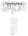
- an electrical box 1 comprises a card 4 equipped and a hood 3.
- the card 4, on which a circuit 5 has been printed includes openings 41, to pass through the clips 11 for retaining the cover 3, and through holes 42, also crossing the tracks of the circuit printed 5, to let pass of legs 71 of components 7 or soldering shanks 81 of a connector 8 integrated in the hood, the tails 81 being integral with the electrical contacts 82 of the connector.
- the housing could be integrated other connectors, as will often be the case.
- SMD Surface mounted components
- the housing 1 is presented in the brazing position of CMS components, and its lower surface 31, that is to say that of the hood 3, rests by gravity on the laying plane of a non-reflow oven represent.
- lugs 13 have been provided on the inner lateral faces of the bonnet 3 and being brazed the card rests on these lugs 13.
- retaining or holding lugs 14 were provided in the bottom of the hood. These retaining tabs can Moreover, be mounted on free slats in flexion. Thus, components are even better tackled against the card, even if their dimensions are at the limits of tolerances.
- the connector 8, integrated in the cover, does not need to be maintained this way. However, to avoid, after brazing, any constraint subsequent mechanics on the welds between the solder shanks 81 and the tracks of the circuit 5, the connector 8 is secured to the cover 3 by arms flexible 12 allowing it to remain floating relative to the hood.
- the connector 8 is accessible through the lower face 31 of the hood 3 through an opening 2 formed in this face 31 leaving the connector play freely in relation to it.
- the card 4 in the reflow position is held by the cover 3, and the cover 3 holds the connector 8 in position relative to the card 4, in particular the welding shanks 81 are maintained sufficiently across the tracks of circuit 5 and to be able to be soldered by reflow at the same time as the CMS 6 components.
- the flexible arms 12, the clips 11 and the lugs 13 can come from material with the hood 3.
- the card, the housing and the cover are arranged to that it is the card which maintains the housing and the connector during the reflow operation.
Landscapes
- Engineering & Computer Science (AREA)
- Microelectronics & Electronic Packaging (AREA)
- Manufacturing & Machinery (AREA)
- Coupling Device And Connection With Printed Circuit (AREA)
- Multi-Conductor Connections (AREA)
Applications Claiming Priority (2)
| Application Number | Priority Date | Filing Date | Title |
|---|---|---|---|
| FR0314950 | 2003-12-18 | ||
| FR0314950A FR2864420B1 (fr) | 2003-12-18 | 2003-12-18 | Boitier electrique a connecteur integre |
Publications (2)
| Publication Number | Publication Date |
|---|---|
| EP1569504A1 true EP1569504A1 (de) | 2005-08-31 |
| EP1569504B1 EP1569504B1 (de) | 2010-05-05 |
Family
ID=34630316
Family Applications (1)
| Application Number | Title | Priority Date | Filing Date |
|---|---|---|---|
| EP20040292973 Expired - Lifetime EP1569504B1 (de) | 2003-12-18 | 2004-12-14 | Elektrisches Gehäuse mit einem integrierten Verbinder |
Country Status (3)
| Country | Link |
|---|---|
| EP (1) | EP1569504B1 (de) |
| DE (1) | DE602004026990D1 (de) |
| FR (1) | FR2864420B1 (de) |
Cited By (2)
| Publication number | Priority date | Publication date | Assignee | Title |
|---|---|---|---|---|
| CN103563501A (zh) * | 2011-06-01 | 2014-02-05 | 丰田自动车株式会社 | 散热结构 |
| WO2014020232A1 (en) * | 2012-07-30 | 2014-02-06 | Nokia Corporation | Audio-visual connector |
Families Citing this family (1)
| Publication number | Priority date | Publication date | Assignee | Title |
|---|---|---|---|---|
| DE102014220325A1 (de) | 2013-10-08 | 2015-04-09 | Johnson Controls Gmbh | Gehäuse für ein elektrisches oder elektronisches Modul |
Citations (5)
| Publication number | Priority date | Publication date | Assignee | Title |
|---|---|---|---|---|
| US4506443A (en) * | 1982-05-28 | 1985-03-26 | Clarion Co., Ltd. | Method of mounting electric part onto a substrate |
| FR2556550A1 (fr) * | 1983-12-09 | 1985-06-14 | Lignes Telegraph Telephon | Procede de brasage de composants electroniques sur un circuit imprime et circuit hybride obtenu par ce procede |
| DE10162600A1 (de) | 2001-12-20 | 2003-07-10 | Bosch Gmbh Robert | Gehäuseanordnung für ein elektrisches Gerät |
| WO2003079743A2 (de) * | 2002-03-15 | 2003-09-25 | Endress + Hauser Gmbh + Co. Kg | Verfahren zum bestücken und löten einer leiterplatte, reflowofen und leiterplatte für ein solches verfahren |
| US20030201310A1 (en) * | 2001-08-01 | 2003-10-30 | Hitachi, Ltd. | Packaging method using lead-free solder |
-
2003
- 2003-12-18 FR FR0314950A patent/FR2864420B1/fr not_active Expired - Fee Related
-
2004
- 2004-12-14 EP EP20040292973 patent/EP1569504B1/de not_active Expired - Lifetime
- 2004-12-14 DE DE200460026990 patent/DE602004026990D1/de not_active Expired - Lifetime
Patent Citations (5)
| Publication number | Priority date | Publication date | Assignee | Title |
|---|---|---|---|---|
| US4506443A (en) * | 1982-05-28 | 1985-03-26 | Clarion Co., Ltd. | Method of mounting electric part onto a substrate |
| FR2556550A1 (fr) * | 1983-12-09 | 1985-06-14 | Lignes Telegraph Telephon | Procede de brasage de composants electroniques sur un circuit imprime et circuit hybride obtenu par ce procede |
| US20030201310A1 (en) * | 2001-08-01 | 2003-10-30 | Hitachi, Ltd. | Packaging method using lead-free solder |
| DE10162600A1 (de) | 2001-12-20 | 2003-07-10 | Bosch Gmbh Robert | Gehäuseanordnung für ein elektrisches Gerät |
| WO2003079743A2 (de) * | 2002-03-15 | 2003-09-25 | Endress + Hauser Gmbh + Co. Kg | Verfahren zum bestücken und löten einer leiterplatte, reflowofen und leiterplatte für ein solches verfahren |
Cited By (4)
| Publication number | Priority date | Publication date | Assignee | Title |
|---|---|---|---|---|
| CN103563501A (zh) * | 2011-06-01 | 2014-02-05 | 丰田自动车株式会社 | 散热结构 |
| CN103563501B (zh) * | 2011-06-01 | 2016-01-20 | 丰田自动车株式会社 | 散热结构 |
| WO2014020232A1 (en) * | 2012-07-30 | 2014-02-06 | Nokia Corporation | Audio-visual connector |
| US9048602B2 (en) | 2012-07-30 | 2015-06-02 | Nokia Technologies Oy | Audio-visual connector |
Also Published As
| Publication number | Publication date |
|---|---|
| EP1569504B1 (de) | 2010-05-05 |
| FR2864420B1 (fr) | 2006-04-28 |
| DE602004026990D1 (de) | 2010-06-17 |
| FR2864420A1 (fr) | 2005-06-24 |
Similar Documents
| Publication | Publication Date | Title |
|---|---|---|
| EP2912725B1 (de) | Elektrischer kontakt und elektronische schaltung | |
| FR2963853A1 (fr) | Dispositif de liaison electrique pour le branchement d'un module electronique a un conducteur plat ayant un grand nombre de chemins conducteurs | |
| CH411070A (fr) | Panneau à circuit imprimé | |
| FR2865098A1 (fr) | Unite de commande electronique et procede pour sa production | |
| FR2885739A1 (fr) | Procede de connexion sans soudure d'un actionneur electrique, notamment pour application aux tableaux de bord automobile, a un circuit imprime | |
| FR2954606A1 (fr) | Connecteur pour carte a circuit electrique, carte a circuit electrique et dispositif de chauffage electrique correspondants | |
| EP2979521A1 (de) | Steuermodul für eine elektrische anwendung | |
| EP1569504B1 (de) | Elektrisches Gehäuse mit einem integrierten Verbinder | |
| EP0312415A1 (de) | Leiterplatten für hohe Ströme und Verfahren zur Herstellung | |
| EP1348614A1 (de) | Montageverfahren für ein Kraftfahrzeug-Ausstattungsmodul und ein Karrosserieteil, und Anordnung für eine derartige Montage | |
| FR3037208A1 (fr) | Procede de fabrication d'une unite de microphone et unite de microphone | |
| EP3932152B1 (de) | Elektronikkarte mit bestandteilen in höhlen und gemeinsamen lötungsbereichen | |
| EP0967712A1 (de) | Unterbaugruppe mit elektronischen Bauelementen für eines Fahrzeugswechselstromgenerators | |
| FR2965139A1 (fr) | Support de circuit et procede de fabrication d'un tel support de circuit | |
| EP1901397B1 (de) | Elektrische Verbindungseinrichtung | |
| EP1581033B1 (de) | Metallplättchen zur elektrischen Verbindung, elektrisches Bauteil mit diesem Plättchen und Verbindungsadapter | |
| FR2746736A1 (fr) | Unite de gestion de vehicule automobile | |
| EP2251883B1 (de) | Anordnung eines Umschalters auf einer Platine mit Druckschaltkreisen und entsprechendes Montageverfahren | |
| FR2697715A1 (fr) | Circuit imprimé double face et ensemble de conduction électrique comprenant un tel circuit imprimé. | |
| FR2693339A1 (fr) | Procédé de liaison et de fixation de composants à broches sur un circuit imprimé souple, et circuit ainsi obtenu. | |
| FR2814860A1 (fr) | Agencement de mise en contact d'un composant de moteur ou de boite de vitesses sur une plaquette de circuit imprime electrique | |
| FR2602629A1 (fr) | Circuit imprime souple a composants en surface, et procede pour le fabriquer | |
| FR3032327A1 (fr) | Procede de montage d'un composant electronique traversant sur une carte a circuit imprime | |
| EP4540896A1 (de) | Mechanische komponente für elektrischen kontakt sowie zugehöriges steuermodul und motorgebläseanordnung | |
| JPH07298452A (ja) | 電気接続箱 |
Legal Events
| Date | Code | Title | Description |
|---|---|---|---|
| PUAI | Public reference made under article 153(3) epc to a published international application that has entered the european phase |
Free format text: ORIGINAL CODE: 0009012 |
|
| AK | Designated contracting states |
Kind code of ref document: A1 Designated state(s): AT BE BG CH CY CZ DE DK EE ES FI FR GB GR HU IE IS IT LI LT LU MC NL PL PT RO SE SI SK TR |
|
| AX | Request for extension of the european patent |
Extension state: AL BA HR LV MK YU |
|
| RIN1 | Information on inventor provided before grant (corrected) |
Inventor name: COMBE, JEAN-CHRISTOPHE Inventor name: MONTAROU, LAURENT |
|
| 17P | Request for examination filed |
Effective date: 20060210 |
|
| AKX | Designation fees paid |
Designated state(s): DE ES FR GB IT |
|
| 17Q | First examination report despatched |
Effective date: 20090128 |
|
| GRAP | Despatch of communication of intention to grant a patent |
Free format text: ORIGINAL CODE: EPIDOSNIGR1 |
|
| GRAS | Grant fee paid |
Free format text: ORIGINAL CODE: EPIDOSNIGR3 |
|
| GRAA | (expected) grant |
Free format text: ORIGINAL CODE: 0009210 |
|
| AK | Designated contracting states |
Kind code of ref document: B1 Designated state(s): DE ES FR GB IT |
|
| REG | Reference to a national code |
Ref country code: GB Ref legal event code: FG4D Free format text: NOT ENGLISH |
|
| REF | Corresponds to: |
Ref document number: 602004026990 Country of ref document: DE Date of ref document: 20100617 Kind code of ref document: P |
|
| PG25 | Lapsed in a contracting state [announced via postgrant information from national office to epo] |
Ref country code: ES Free format text: LAPSE BECAUSE OF FAILURE TO SUBMIT A TRANSLATION OF THE DESCRIPTION OR TO PAY THE FEE WITHIN THE PRESCRIBED TIME-LIMIT Effective date: 20100816 |
|
| PLBE | No opposition filed within time limit |
Free format text: ORIGINAL CODE: 0009261 |
|
| STAA | Information on the status of an ep patent application or granted ep patent |
Free format text: STATUS: NO OPPOSITION FILED WITHIN TIME LIMIT |
|
| PG25 | Lapsed in a contracting state [announced via postgrant information from national office to epo] |
Ref country code: IT Free format text: LAPSE BECAUSE OF FAILURE TO SUBMIT A TRANSLATION OF THE DESCRIPTION OR TO PAY THE FEE WITHIN THE PRESCRIBED TIME-LIMIT Effective date: 20100505 |
|
| 26N | No opposition filed |
Effective date: 20110208 |
|
| REG | Reference to a national code |
Ref country code: DE Ref legal event code: R097 Ref document number: 602004026990 Country of ref document: DE Effective date: 20110207 |
|
| GBPC | Gb: european patent ceased through non-payment of renewal fee |
Effective date: 20101214 |
|
| PG25 | Lapsed in a contracting state [announced via postgrant information from national office to epo] |
Ref country code: GB Free format text: LAPSE BECAUSE OF NON-PAYMENT OF DUE FEES Effective date: 20101214 |
|
| REG | Reference to a national code |
Ref country code: FR Ref legal event code: PLFP Year of fee payment: 12 |
|
| REG | Reference to a national code |
Ref country code: FR Ref legal event code: PLFP Year of fee payment: 13 |
|
| REG | Reference to a national code |
Ref country code: FR Ref legal event code: PLFP Year of fee payment: 14 |
|
| PGFP | Annual fee paid to national office [announced via postgrant information from national office to epo] |
Ref country code: FR Payment date: 20171221 Year of fee payment: 14 |
|
| PGFP | Annual fee paid to national office [announced via postgrant information from national office to epo] |
Ref country code: DE Payment date: 20171228 Year of fee payment: 14 |
|
| REG | Reference to a national code |
Ref country code: DE Ref legal event code: R119 Ref document number: 602004026990 Country of ref document: DE |
|
| PG25 | Lapsed in a contracting state [announced via postgrant information from national office to epo] |
Ref country code: FR Free format text: LAPSE BECAUSE OF NON-PAYMENT OF DUE FEES Effective date: 20181231 Ref country code: DE Free format text: LAPSE BECAUSE OF NON-PAYMENT OF DUE FEES Effective date: 20190702 |