EP1568952A1 - Reversible heat pump system - Google Patents
Reversible heat pump system Download PDFInfo
- Publication number
- EP1568952A1 EP1568952A1 EP04251121A EP04251121A EP1568952A1 EP 1568952 A1 EP1568952 A1 EP 1568952A1 EP 04251121 A EP04251121 A EP 04251121A EP 04251121 A EP04251121 A EP 04251121A EP 1568952 A1 EP1568952 A1 EP 1568952A1
- Authority
- EP
- European Patent Office
- Prior art keywords
- evaporator
- condenser
- valve
- control valve
- heat exchanger
- Prior art date
- Legal status (The legal status is an assumption and is not a legal conclusion. Google has not performed a legal analysis and makes no representation as to the accuracy of the status listed.)
- Withdrawn
Links
Images
Classifications
-
- F—MECHANICAL ENGINEERING; LIGHTING; HEATING; WEAPONS; BLASTING
- F25—REFRIGERATION OR COOLING; COMBINED HEATING AND REFRIGERATION SYSTEMS; HEAT PUMP SYSTEMS; MANUFACTURE OR STORAGE OF ICE; LIQUEFACTION SOLIDIFICATION OF GASES
- F25B—REFRIGERATION MACHINES, PLANTS OR SYSTEMS; COMBINED HEATING AND REFRIGERATION SYSTEMS; HEAT PUMP SYSTEMS
- F25B13/00—Compression machines, plants or systems, with reversible cycle
-
- B—PERFORMING OPERATIONS; TRANSPORTING
- B60—VEHICLES IN GENERAL
- B60H—ARRANGEMENTS OF HEATING, COOLING, VENTILATING OR OTHER AIR-TREATING DEVICES SPECIALLY ADAPTED FOR PASSENGER OR GOODS SPACES OF VEHICLES
- B60H1/00—Heating, cooling or ventilating [HVAC] devices
- B60H1/00642—Control systems or circuits; Control members or indication devices for heating, cooling or ventilating devices
- B60H1/00814—Control systems or circuits characterised by their output, for controlling particular components of the heating, cooling or ventilating installation
- B60H1/00878—Control systems or circuits characterised by their output, for controlling particular components of the heating, cooling or ventilating installation the components being temperature regulating devices
- B60H1/00899—Controlling the flow of liquid in a heat pump system
- B60H1/00907—Controlling the flow of liquid in a heat pump system where the flow direction of the refrigerant changes and an evaporator becomes condenser
-
- F—MECHANICAL ENGINEERING; LIGHTING; HEATING; WEAPONS; BLASTING
- F24—HEATING; RANGES; VENTILATING
- F24F—AIR-CONDITIONING; AIR-HUMIDIFICATION; VENTILATION; USE OF AIR CURRENTS FOR SCREENING
- F24F3/00—Air-conditioning systems in which conditioned primary air is supplied from one or more central stations to distributing units in the rooms or spaces where it may receive secondary treatment; Apparatus specially designed for such systems
- F24F3/12—Air-conditioning systems in which conditioned primary air is supplied from one or more central stations to distributing units in the rooms or spaces where it may receive secondary treatment; Apparatus specially designed for such systems characterised by the treatment of the air otherwise than by heating and cooling
- F24F3/14—Air-conditioning systems in which conditioned primary air is supplied from one or more central stations to distributing units in the rooms or spaces where it may receive secondary treatment; Apparatus specially designed for such systems characterised by the treatment of the air otherwise than by heating and cooling by humidification; by dehumidification
- F24F3/153—Air-conditioning systems in which conditioned primary air is supplied from one or more central stations to distributing units in the rooms or spaces where it may receive secondary treatment; Apparatus specially designed for such systems characterised by the treatment of the air otherwise than by heating and cooling by humidification; by dehumidification with subsequent heating, i.e. with the air, given the required humidity in the central station, passing a heating element to achieve the required temperature
-
- B—PERFORMING OPERATIONS; TRANSPORTING
- B60—VEHICLES IN GENERAL
- B60H—ARRANGEMENTS OF HEATING, COOLING, VENTILATING OR OTHER AIR-TREATING DEVICES SPECIALLY ADAPTED FOR PASSENGER OR GOODS SPACES OF VEHICLES
- B60H1/00—Heating, cooling or ventilating [HVAC] devices
- B60H1/00642—Control systems or circuits; Control members or indication devices for heating, cooling or ventilating devices
- B60H1/00814—Control systems or circuits characterised by their output, for controlling particular components of the heating, cooling or ventilating installation
- B60H1/00878—Control systems or circuits characterised by their output, for controlling particular components of the heating, cooling or ventilating installation the components being temperature regulating devices
- B60H2001/00935—Control systems or circuits characterised by their output, for controlling particular components of the heating, cooling or ventilating installation the components being temperature regulating devices comprising four way valves for controlling the fluid direction
-
- B—PERFORMING OPERATIONS; TRANSPORTING
- B60—VEHICLES IN GENERAL
- B60H—ARRANGEMENTS OF HEATING, COOLING, VENTILATING OR OTHER AIR-TREATING DEVICES SPECIALLY ADAPTED FOR PASSENGER OR GOODS SPACES OF VEHICLES
- B60H1/00—Heating, cooling or ventilating [HVAC] devices
- B60H1/00642—Control systems or circuits; Control members or indication devices for heating, cooling or ventilating devices
- B60H1/00814—Control systems or circuits characterised by their output, for controlling particular components of the heating, cooling or ventilating installation
- B60H1/00878—Control systems or circuits characterised by their output, for controlling particular components of the heating, cooling or ventilating installation the components being temperature regulating devices
- B60H2001/00949—Control systems or circuits characterised by their output, for controlling particular components of the heating, cooling or ventilating installation the components being temperature regulating devices comprising additional heating/cooling sources, e.g. second evaporator
-
- F—MECHANICAL ENGINEERING; LIGHTING; HEATING; WEAPONS; BLASTING
- F25—REFRIGERATION OR COOLING; COMBINED HEATING AND REFRIGERATION SYSTEMS; HEAT PUMP SYSTEMS; MANUFACTURE OR STORAGE OF ICE; LIQUEFACTION SOLIDIFICATION OF GASES
- F25B—REFRIGERATION MACHINES, PLANTS OR SYSTEMS; COMBINED HEATING AND REFRIGERATION SYSTEMS; HEAT PUMP SYSTEMS
- F25B2313/00—Compression machines, plants or systems with reversible cycle not otherwise provided for
- F25B2313/023—Compression machines, plants or systems with reversible cycle not otherwise provided for using multiple indoor units
- F25B2313/0232—Compression machines, plants or systems with reversible cycle not otherwise provided for using multiple indoor units with bypasses
-
- F—MECHANICAL ENGINEERING; LIGHTING; HEATING; WEAPONS; BLASTING
- F25—REFRIGERATION OR COOLING; COMBINED HEATING AND REFRIGERATION SYSTEMS; HEAT PUMP SYSTEMS; MANUFACTURE OR STORAGE OF ICE; LIQUEFACTION SOLIDIFICATION OF GASES
- F25B—REFRIGERATION MACHINES, PLANTS OR SYSTEMS; COMBINED HEATING AND REFRIGERATION SYSTEMS; HEAT PUMP SYSTEMS
- F25B2313/00—Compression machines, plants or systems with reversible cycle not otherwise provided for
- F25B2313/023—Compression machines, plants or systems with reversible cycle not otherwise provided for using multiple indoor units
- F25B2313/0234—Compression machines, plants or systems with reversible cycle not otherwise provided for using multiple indoor units in series arrangements
- F25B2313/02343—Compression machines, plants or systems with reversible cycle not otherwise provided for using multiple indoor units in series arrangements during dehumidification
Definitions
- This invention relates to a reversible heat pump system suitable for heating and air conditioning use in motor vehicles.
- Vehicle air conditioning systems are well established. Conventionally, the air conditioning system is used only to cool the passenger compartment, with heating being separately provided using waste engine heat.
- cooling mode is referred to as "air conditioning” or "A/C”
- heating mode is referred to as "heat pump” operation. This is desirable, for example, where the available engine heat is limited, as with high efficiency diesel engines. Examples of reversible systems are shown in GB 2,375,596A, US 4,991,405, and EP 1,247,670.
- the present invention provides a reversible heat pump system for use in heating and cooling a given space, comprising:
- the system can be selectively operated in a heat pump mode, an A/C mode, or a de-fogging mode.
- the system comprises a compressor 10 having an inlet 12 connected to a reversing valve 14 via an accumulator-drier 16, and an outlet 18 also connected to the reversing valve 14.
- the inlet 12 is also connected to an air conditioning evaporator 20.
- the AC evaporator 20 is positioned in the vehicle interior along with a heat pump condenser 22.
- a heating ventilating and air conditioning air flow 36 produced by a suitable fan, can be directed across the AC evaporator 20 and subsequently the HP condenser 22 and thence into the vehicle interior.
- An outside heat exchanger 24 is positioned exteriorly of the vehicle cabin.
- One side of the HP condenser 22 is connected to the reversing valve 14, and the other side via an orifice tube 26 and check valve 28 to a control valve 30.
- the AC evaporator 20 is connected between the accumulator drier 16 and the control valve 30 via an orifice tube 32 and a valve 34.
- the outside heat exchanger 24 is connected between the opposite side of the control valve 30 and the reversing valve 14.
- the system is thus similar to prior art reversible systems except for the addition of the control valve 30.
- FIG. 2 shows the system operating in air conditioning (cooling) mode.
- the control valve 30 is open, as is the AC evaporator valve 34.
- Refrigerant circulates as shown, with the outside heat exchanger 24 acting as a condenser.
- Flow through the HP condenser 22 is prevented by the check valve 28.
- FIG. 3 shows the system operating in heat pump (heating) mode.
- the control valve 30 is open, and the AC evaporator valve 34 is closed.
- Refrigerant circulates as shown, with the outside heat exchanger 24 acting as an evaporator.
- FIG. 4 shows the system operating in defogging mode. With the AC evaporator valve 34 open and the control valve 30 closed, refrigerant circulates as shown in full lines. In this condition, the AC evaporator 20 acts as the system evaporator, the HP condenser 22 acts as the system condenser, and the outside heat exchanger 24 is inoperative.
- the air flow 36 passes first through the AC evaporator 20 which cools the air below its dew point thereby removing moisture. This air is then reheated by passing through the HP condenser 22. In this condition the heat extracted from the air by the AC evaporator 20 plus that supplied by the compressor 10 is supplied to the air at the HP condenser 22.
- control valve 30 can be partially opened, giving the refrigerant flow indicated in dashed lines. In this condition, additional heat is added to the system from the outside heat exchanger 24.
- the AC evaporator 20 may be provided with a sensor (not shown) for detecting freezing of the evaporator, the control valve 30 being partially opened in response to evaporator freezing to provide additional heat.
- An automatic control may be added to produce gradual opening of the control valve 30 accompanied by gradual closing of the AC evaporator valve 34, in order to achieve a gradual transition from defogging to heat pump mode.
- the foregoing embodiment is suitable for use with conventional refrigerant. If a gas such as carbon dioxide is sued as the refrigerant, the condenser would be replaced by a gas cooler.
- the invention is particularly useful in vehicles such as cars, but may also be used in other forms of HVAC systems. Modifications may be made to the foregoing embodiment within the scope of the appended claims.
Landscapes
- Engineering & Computer Science (AREA)
- Mechanical Engineering (AREA)
- Physics & Mathematics (AREA)
- Thermal Sciences (AREA)
- General Engineering & Computer Science (AREA)
- Chemical & Material Sciences (AREA)
- Combustion & Propulsion (AREA)
- Air-Conditioning For Vehicles (AREA)
Abstract
The system comprises a compressor (10), an outside
heat exchanger (24), and an evaporator (20) and
condenser (22) both positioned internally of a space
such as a vehicle cabin. In a cooling mode, the
compressor (10) circulates refrigerant around the
outside heat exchanger (24) acting as a condenser
and the evaporator (20). In a heating mode,
refrigerant is circulated around the outside heat
exchanger (24) acting as an evaporator and the
condenser (22). In a third mode, the outside heat
exchanger (24) is isolated and refrigerant is
circulated around the condenser (22) and evaporator
(20). The third mode is useful for providing
defogging and heat at the same time. Choice of mode
is controlled by a control valve (30) acting in
conjunction with reversing valve (14), evaporator
valve (34) and condenser check valve (28).
Description
- This invention relates to a reversible heat pump system suitable for heating and air conditioning use in motor vehicles.
- Vehicle air conditioning systems are well established. Conventionally, the air conditioning system is used only to cool the passenger compartment, with heating being separately provided using waste engine heat.
- It is also known, although less common, for such systems to be reversible so as to be usable for cooling or heating the passenger compartment. In the present application, the cooling mode is referred to as "air conditioning" or "A/C", while the heating mode is referred to as "heat pump" operation. This is desirable, for example, where the available engine heat is limited, as with high efficiency diesel engines. Examples of reversible systems are shown in GB 2,375,596A, US 4,991,405, and EP 1,247,670.
- There are, however, situations in which it would be desirable to provide both air conditioning and heat pump operation simultaneously, especially for simultaneous heating and de-fogging of the passenger compartment.
- Accordingly, the present invention provides a reversible heat pump system for use in heating and cooling a given space, comprising:
- a compressor;
- an outside heat exchanger which, in use, is positioned outside said space;
- an inside heat exchanger positioned, in use, inside said space; and
- a reversing valve connected to the compressor such that the outside heat exchanger can be connected to act as a condenser or an evaporator;
- and is characterised in that:
- the inside heat exchanger comprises an evaporator and a condenser or gas cooler;
- a control valve is positioned such that closure of the control valve prevents flow through the outside heat exchanger; and
- further valve means are provided which are operable, when said control valve is fully or partially closed, to permit refrigerant to flow through the condenser or gas cooler and the evaporator sequentially.
-
- In this way, the system can be selectively operated in a heat pump mode, an A/C mode, or a de-fogging mode.
- Preferred features and advantages of the invention will be apparent from the claims and the following description.
- An embodiment of the invention will now be described, by way of example only, with reference to the drawings, in which:
- Figure 1 is a schematic of one form of reversible heat pump system in accordance with the invention;
- Figure 2 shows the system of Figure 1 in operation in air conditioning (cooling) mode;
- Figure 3 shows the system of Figure 1 in operation in heat pump (heating) mode; and
- Figure 4 shows the system of Figure 1 in operation in a defogging mode.
-
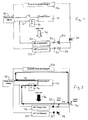
- Referring to Figure 1, the system comprises a
compressor 10 having aninlet 12 connected to a reversing valve 14 via an accumulator-drier 16, and anoutlet 18 also connected to the reversing valve 14. Theinlet 12 is also connected to anair conditioning evaporator 20. - The
AC evaporator 20 is positioned in the vehicle interior along with aheat pump condenser 22. A heating ventilating and airconditioning air flow 36, produced by a suitable fan, can be directed across theAC evaporator 20 and subsequently the HP condenser 22 and thence into the vehicle interior. Anoutside heat exchanger 24 is positioned exteriorly of the vehicle cabin. - One side of the HP
condenser 22 is connected to the reversing valve 14, and the other side via anorifice tube 26 and checkvalve 28 to acontrol valve 30. TheAC evaporator 20 is connected between theaccumulator drier 16 and thecontrol valve 30 via anorifice tube 32 and avalve 34. Theoutside heat exchanger 24 is connected between the opposite side of thecontrol valve 30 and the reversing valve 14. - The system is thus similar to prior art reversible systems except for the addition of the
control valve 30. - Figure 2 shows the system operating in air conditioning (cooling) mode. The
control valve 30 is open, as is theAC evaporator valve 34. Refrigerant circulates as shown, with theoutside heat exchanger 24 acting as a condenser. Flow through the HPcondenser 22 is prevented by thecheck valve 28. - Figure 3 shows the system operating in heat pump (heating) mode. The
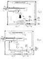
control valve 30 is open, and theAC evaporator valve 34 is closed. Refrigerant circulates as shown, with theoutside heat exchanger 24 acting as an evaporator. - Figure 4 shows the system operating in defogging mode. With the
AC evaporator valve 34 open and thecontrol valve 30 closed, refrigerant circulates as shown in full lines. In this condition, theAC evaporator 20 acts as the system evaporator, the HP condenser 22 acts as the system condenser, and theoutside heat exchanger 24 is inoperative. - The
air flow 36 passes first through theAC evaporator 20 which cools the air below its dew point thereby removing moisture. This air is then reheated by passing through the HPcondenser 22. In this condition the heat extracted from the air by theAC evaporator 20 plus that supplied by thecompressor 10 is supplied to the air at the HPcondenser 22. - Alternatively, the
control valve 30 can be partially opened, giving the refrigerant flow indicated in dashed lines. In this condition, additional heat is added to the system from theoutside heat exchanger 24. - The
AC evaporator 20 may be provided with a sensor (not shown) for detecting freezing of the evaporator, thecontrol valve 30 being partially opened in response to evaporator freezing to provide additional heat. - An automatic control may be added to produce gradual opening of the
control valve 30 accompanied by gradual closing of theAC evaporator valve 34, in order to achieve a gradual transition from defogging to heat pump mode. - The foregoing embodiment is suitable for use with conventional refrigerant. If a gas such as carbon dioxide is sued as the refrigerant, the condenser would be replaced by a gas cooler.
- The invention is particularly useful in vehicles such as cars, but may also be used in other forms of HVAC systems. Modifications may be made to the foregoing embodiment within the scope of the appended claims.
Claims (7)
- A reversible heat pump system for use in heating and cooling a given space, comprising:characterised in that:a compressor (10);an outside heat exchanger (24) which, in use, is positioned outside said space;an inside heat exchanger (20, 22) positioned, in use, inside said space; anda reversing valve (14) connected to the compressor (10) such that the outside heat exchanger (24) can be connected to act as a condenser or an evaporator;the inside heat exchanger comprises an evaporator (20) and a condenser (22) or gas cooler;a control valve (30) is positioned such that closure of the control valve (30) prevents flow through the outside heat exchanger (24); andfurther valve means (28,34) are provided which are operable, when said control (30) valve is fully or partially closed, to permit compressed refrigerant to flow through the condenser (22) or gas cooler and the evaporator (20) sequentially.
- A system according to claim 1, including a fan arranged to pass an airflow (36) over the evaporator (20) and the condenser (22) or gas cooler sequentially.
- A system according to claim 1 or claim 2, in which the evaporator (20) and the condenser (22) or gas cooler are connected in parallel to the control valve (30); and said further valve means (28,34) comprises a controllable valve (34) between the evaporator (20) and the control valve (30), and a check valve (28) between the condenser (22) or gas cooler and the control valve (30) permitting flow only from the condenser (22) or gas cooler to the control valve (30).
- A system according to claim 3, in which a first orifice tube (32) is provided between the evaporator (20) and the controllable valve (34), and a second orifice tube (26) is provided between the condenser (22) and the check valve (28).
- A system according to any preceding claim, in which freezing of the evaporator (20) causes the control valve (30) to be partially opened.
- A system according to any preceding claim, in which an accumulator-drier (16) is provided at the inlet to the compressor (10).
- A system according to any preceding claim, in which pressure differences across the system cause the control valve (30) to be partially open thereby enabling smooth transition from one mode to another.
Priority Applications (1)
| Application Number | Priority Date | Filing Date | Title |
|---|---|---|---|
| EP04251121A EP1568952A1 (en) | 2004-02-27 | 2004-02-27 | Reversible heat pump system |
Applications Claiming Priority (1)
| Application Number | Priority Date | Filing Date | Title |
|---|---|---|---|
| EP04251121A EP1568952A1 (en) | 2004-02-27 | 2004-02-27 | Reversible heat pump system |
Publications (1)
| Publication Number | Publication Date |
|---|---|
| EP1568952A1 true EP1568952A1 (en) | 2005-08-31 |
Family
ID=34746109
Family Applications (1)
| Application Number | Title | Priority Date | Filing Date |
|---|---|---|---|
| EP04251121A Withdrawn EP1568952A1 (en) | 2004-02-27 | 2004-02-27 | Reversible heat pump system |
Country Status (1)
| Country | Link |
|---|---|
| EP (1) | EP1568952A1 (en) |
Cited By (3)
| Publication number | Priority date | Publication date | Assignee | Title |
|---|---|---|---|---|
| EP1695849A1 (en) * | 2005-02-28 | 2006-08-30 | Sanyo Electric Co., Ltd. | Refrigerant cycle unit |
| EP2626223A1 (en) * | 2012-02-07 | 2013-08-14 | LG Electronics, Inc. | Air conditioner for electric vehicle |
| CN103673365A (en) * | 2013-12-24 | 2014-03-26 | 镇江市博林光电科技有限公司 | Both-way dual-condensation refrigerating system |
Citations (15)
| Publication number | Priority date | Publication date | Assignee | Title |
|---|---|---|---|---|
| JPH04158172A (en) * | 1990-10-19 | 1992-06-01 | Sharp Corp | Air conditioner |
| US5181392A (en) * | 1990-03-02 | 1993-01-26 | Hitachi Ltd. | Air conditioner and heat exchanger used therein |
| JPH06101933A (en) * | 1992-09-22 | 1994-04-12 | Nippondenso Co Ltd | Heat pump type air-conditioner in vehicular application |
| JPH06147690A (en) * | 1992-11-12 | 1994-05-27 | Zexel Corp | Air conditioning apparatus |
| JPH06147689A (en) * | 1992-11-12 | 1994-05-27 | Zexel Corp | Air conditioning apparatus |
| JPH0840060A (en) * | 1994-08-04 | 1996-02-13 | Matsushita Electric Ind Co Ltd | Heat pump air-conditioning and dehumidifying device for electric automobile |
| US5598887A (en) * | 1993-10-14 | 1997-02-04 | Sanden Corporation | Air conditioner for vehicles |
| US5689962A (en) * | 1996-05-24 | 1997-11-25 | Store Heat And Produce Energy, Inc. | Heat pump systems and methods incorporating subcoolers for conditioning air |
| US5704219A (en) * | 1995-08-01 | 1998-01-06 | Nippondenso Co., Ltd. | Air conditioning apparatus |
| US5782102A (en) * | 1992-04-24 | 1998-07-21 | Nippondenso Co., Ltd. | Automotive air conditioner having condenser and evaporator provided within air duct |
| JPH11139154A (en) * | 1997-11-07 | 1999-05-25 | Tgk Co Ltd | Air conditioner for automobile |
| US5996360A (en) * | 1997-11-27 | 1999-12-07 | Denso Corporation | Refrigerant cycle system |
| EP0989003A2 (en) * | 1998-09-24 | 2000-03-29 | Denso Corporation | Heat pump type refrigerant cycle system |
| JP2003083629A (en) * | 2001-09-12 | 2003-03-19 | Mitsubishi Heavy Ind Ltd | Refrigerant circuit and structure of heat exchanger |
| WO2003051657A1 (en) * | 2001-12-19 | 2003-06-26 | Sinvent As | Vapor compression system for heating and cooling of vehicles |
-
2004
- 2004-02-27 EP EP04251121A patent/EP1568952A1/en not_active Withdrawn
Patent Citations (15)
| Publication number | Priority date | Publication date | Assignee | Title |
|---|---|---|---|---|
| US5181392A (en) * | 1990-03-02 | 1993-01-26 | Hitachi Ltd. | Air conditioner and heat exchanger used therein |
| JPH04158172A (en) * | 1990-10-19 | 1992-06-01 | Sharp Corp | Air conditioner |
| US5782102A (en) * | 1992-04-24 | 1998-07-21 | Nippondenso Co., Ltd. | Automotive air conditioner having condenser and evaporator provided within air duct |
| JPH06101933A (en) * | 1992-09-22 | 1994-04-12 | Nippondenso Co Ltd | Heat pump type air-conditioner in vehicular application |
| JPH06147690A (en) * | 1992-11-12 | 1994-05-27 | Zexel Corp | Air conditioning apparatus |
| JPH06147689A (en) * | 1992-11-12 | 1994-05-27 | Zexel Corp | Air conditioning apparatus |
| US5598887A (en) * | 1993-10-14 | 1997-02-04 | Sanden Corporation | Air conditioner for vehicles |
| JPH0840060A (en) * | 1994-08-04 | 1996-02-13 | Matsushita Electric Ind Co Ltd | Heat pump air-conditioning and dehumidifying device for electric automobile |
| US5704219A (en) * | 1995-08-01 | 1998-01-06 | Nippondenso Co., Ltd. | Air conditioning apparatus |
| US5689962A (en) * | 1996-05-24 | 1997-11-25 | Store Heat And Produce Energy, Inc. | Heat pump systems and methods incorporating subcoolers for conditioning air |
| JPH11139154A (en) * | 1997-11-07 | 1999-05-25 | Tgk Co Ltd | Air conditioner for automobile |
| US5996360A (en) * | 1997-11-27 | 1999-12-07 | Denso Corporation | Refrigerant cycle system |
| EP0989003A2 (en) * | 1998-09-24 | 2000-03-29 | Denso Corporation | Heat pump type refrigerant cycle system |
| JP2003083629A (en) * | 2001-09-12 | 2003-03-19 | Mitsubishi Heavy Ind Ltd | Refrigerant circuit and structure of heat exchanger |
| WO2003051657A1 (en) * | 2001-12-19 | 2003-06-26 | Sinvent As | Vapor compression system for heating and cooling of vehicles |
Non-Patent Citations (6)
| Title |
|---|
| PATENT ABSTRACTS OF JAPAN vol. 016, no. 450 (M - 1312) 18 September 1992 (1992-09-18) * |
| PATENT ABSTRACTS OF JAPAN vol. 018, no. 380 (M - 1639) 18 July 1994 (1994-07-18) * |
| PATENT ABSTRACTS OF JAPAN vol. 018, no. 472 (M - 1667) 2 September 1994 (1994-09-02) * |
| PATENT ABSTRACTS OF JAPAN vol. 1996, no. 06 28 June 1996 (1996-06-28) * |
| PATENT ABSTRACTS OF JAPAN vol. 1999, no. 10 31 August 1999 (1999-08-31) * |
| PATENT ABSTRACTS OF JAPAN vol. 2003, no. 07 3 July 2003 (2003-07-03) * |
Cited By (5)
| Publication number | Priority date | Publication date | Assignee | Title |
|---|---|---|---|---|
| EP1695849A1 (en) * | 2005-02-28 | 2006-08-30 | Sanyo Electric Co., Ltd. | Refrigerant cycle unit |
| US7461517B2 (en) | 2005-02-28 | 2008-12-09 | Sanyo Electric Co., Ltd. | Refrigerant cycle unit |
| EP2626223A1 (en) * | 2012-02-07 | 2013-08-14 | LG Electronics, Inc. | Air conditioner for electric vehicle |
| CN103673365A (en) * | 2013-12-24 | 2014-03-26 | 镇江市博林光电科技有限公司 | Both-way dual-condensation refrigerating system |
| CN103673365B (en) * | 2013-12-24 | 2016-08-17 | 镇江市博林光电科技有限公司 | Two-way pair of condensation refrigerating system |
Similar Documents
| Publication | Publication Date | Title |
|---|---|---|
| JP3841039B2 (en) | Air conditioner for vehicles | |
| CN105263732B (en) | Air conditioner for vehicles | |
| US8997503B2 (en) | Vehicle air-conditioning system and operation control method therefor | |
| US20050072175A1 (en) | Air conditioner and truck equipped with same | |
| JP3156801B2 (en) | Automotive air conditioners | |
| WO2015097988A1 (en) | Vehicle air-conditioning device | |
| JP2010111222A (en) | Air-conditioner for vehicle | |
| JP6415943B2 (en) | Heat pump air conditioning system for vehicles | |
| WO2000061395A1 (en) | Air conditioner for vehicle | |
| JPWO2011125694A1 (en) | Heat pump air conditioning system for vehicles | |
| US10006684B2 (en) | Air conditioning system for use in vehicle | |
| JP2010260450A (en) | Air conditioner for vehicle | |
| JPS5981214A (en) | Device for heating, ventilating and cooling compartment | |
| WO2015097987A1 (en) | Vehicle air-conditioning device | |
| JPH09109669A (en) | Air conditioner for electric vehicle | |
| JP6341021B2 (en) | Air conditioner for vehicles | |
| EP1568952A1 (en) | Reversible heat pump system | |
| JP4013717B2 (en) | Air conditioner for vehicles | |
| EP3386786B1 (en) | Air conditioning system for use in vehicle | |
| JPH08313123A (en) | Heat pump type cooler and heater for vehicle | |
| JP4428290B2 (en) | Air conditioner for vehicles | |
| JP2004521018A (en) | How to operate an air conditioner | |
| WO2006059410A1 (en) | Air conditioner for vehicle | |
| EP1623857B2 (en) | HVAC Systems | |
| JP2011225187A (en) | Heat pump type air conditioning system for vehicle |
Legal Events
| Date | Code | Title | Description |
|---|---|---|---|
| PUAI | Public reference made under article 153(3) epc to a published international application that has entered the european phase |
Free format text: ORIGINAL CODE: 0009012 |
|
| AK | Designated contracting states |
Kind code of ref document: A1 Designated state(s): AT BE BG CH CY CZ DE DK EE ES FI FR GB GR HU IE IT LI LU MC NL PT RO SE SI SK TR |
|
| AX | Request for extension of the european patent |
Extension state: AL LT LV MK |
|
| AKX | Designation fees paid | ||
| REG | Reference to a national code |
Ref country code: DE Ref legal event code: 8566 |
|
| STAA | Information on the status of an ep patent application or granted ep patent |
Free format text: STATUS: THE APPLICATION IS DEEMED TO BE WITHDRAWN |
|
| 18D | Application deemed to be withdrawn |
Effective date: 20060301 |