EP1568931A1 - Fluid coupling and method of designing the same - Google Patents
Fluid coupling and method of designing the same Download PDFInfo
- Publication number
- EP1568931A1 EP1568931A1 EP03770065A EP03770065A EP1568931A1 EP 1568931 A1 EP1568931 A1 EP 1568931A1 EP 03770065 A EP03770065 A EP 03770065A EP 03770065 A EP03770065 A EP 03770065A EP 1568931 A1 EP1568931 A1 EP 1568931A1
- Authority
- EP
- European Patent Office
- Prior art keywords
- gasket
- ridge
- coupling
- face
- thrust
- Prior art date
- Legal status (The legal status is an assumption and is not a legal conclusion. Google has not performed a legal analysis and makes no representation as to the accuracy of the status listed.)
- Withdrawn
Links
Images




Classifications
-
- F—MECHANICAL ENGINEERING; LIGHTING; HEATING; WEAPONS; BLASTING
- F16—ENGINEERING ELEMENTS AND UNITS; GENERAL MEASURES FOR PRODUCING AND MAINTAINING EFFECTIVE FUNCTIONING OF MACHINES OR INSTALLATIONS; THERMAL INSULATION IN GENERAL
- F16L—PIPES; JOINTS OR FITTINGS FOR PIPES; SUPPORTS FOR PIPES, CABLES OR PROTECTIVE TUBING; MEANS FOR THERMAL INSULATION IN GENERAL
- F16L23/00—Flanged joints
- F16L23/16—Flanged joints characterised by the sealing means
-
- F—MECHANICAL ENGINEERING; LIGHTING; HEATING; WEAPONS; BLASTING
- F16—ENGINEERING ELEMENTS AND UNITS; GENERAL MEASURES FOR PRODUCING AND MAINTAINING EFFECTIVE FUNCTIONING OF MACHINES OR INSTALLATIONS; THERMAL INSULATION IN GENERAL
- F16J—PISTONS; CYLINDERS; SEALINGS
- F16J15/00—Sealings
- F16J15/02—Sealings between relatively-stationary surfaces
- F16J15/06—Sealings between relatively-stationary surfaces with solid packing compressed between sealing surfaces
- F16J15/08—Sealings between relatively-stationary surfaces with solid packing compressed between sealing surfaces with exclusively metal packing
- F16J15/0887—Sealings between relatively-stationary surfaces with solid packing compressed between sealing surfaces with exclusively metal packing the sealing effect being obtained by elastic deformation of the packing
-
- F—MECHANICAL ENGINEERING; LIGHTING; HEATING; WEAPONS; BLASTING
- F16—ENGINEERING ELEMENTS AND UNITS; GENERAL MEASURES FOR PRODUCING AND MAINTAINING EFFECTIVE FUNCTIONING OF MACHINES OR INSTALLATIONS; THERMAL INSULATION IN GENERAL
- F16J—PISTONS; CYLINDERS; SEALINGS
- F16J15/00—Sealings
- F16J15/02—Sealings between relatively-stationary surfaces
- F16J15/06—Sealings between relatively-stationary surfaces with solid packing compressed between sealing surfaces
- F16J15/08—Sealings between relatively-stationary surfaces with solid packing compressed between sealing surfaces with exclusively metal packing
-
- F—MECHANICAL ENGINEERING; LIGHTING; HEATING; WEAPONS; BLASTING
- F16—ENGINEERING ELEMENTS AND UNITS; GENERAL MEASURES FOR PRODUCING AND MAINTAINING EFFECTIVE FUNCTIONING OF MACHINES OR INSTALLATIONS; THERMAL INSULATION IN GENERAL
- F16J—PISTONS; CYLINDERS; SEALINGS
- F16J15/00—Sealings
- F16J15/02—Sealings between relatively-stationary surfaces
- F16J15/06—Sealings between relatively-stationary surfaces with solid packing compressed between sealing surfaces
- F16J15/08—Sealings between relatively-stationary surfaces with solid packing compressed between sealing surfaces with exclusively metal packing
- F16J15/0881—Sealings between relatively-stationary surfaces with solid packing compressed between sealing surfaces with exclusively metal packing the sealing effect being obtained by plastic deformation of the packing
-
- F—MECHANICAL ENGINEERING; LIGHTING; HEATING; WEAPONS; BLASTING
- F16—ENGINEERING ELEMENTS AND UNITS; GENERAL MEASURES FOR PRODUCING AND MAINTAINING EFFECTIVE FUNCTIONING OF MACHINES OR INSTALLATIONS; THERMAL INSULATION IN GENERAL
- F16L—PIPES; JOINTS OR FITTINGS FOR PIPES; SUPPORTS FOR PIPES, CABLES OR PROTECTIVE TUBING; MEANS FOR THERMAL INSULATION IN GENERAL
- F16L23/00—Flanged joints
- F16L23/16—Flanged joints characterised by the sealing means
- F16L23/18—Flanged joints characterised by the sealing means the sealing means being rings
- F16L23/20—Flanged joints characterised by the sealing means the sealing means being rings made exclusively of metal
-
- F—MECHANICAL ENGINEERING; LIGHTING; HEATING; WEAPONS; BLASTING
- F16—ENGINEERING ELEMENTS AND UNITS; GENERAL MEASURES FOR PRODUCING AND MAINTAINING EFFECTIVE FUNCTIONING OF MACHINES OR INSTALLATIONS; THERMAL INSULATION IN GENERAL
- F16B—DEVICES FOR FASTENING OR SECURING CONSTRUCTIONAL ELEMENTS OR MACHINE PARTS TOGETHER, e.g. NAILS, BOLTS, CIRCLIPS, CLAMPS, CLIPS OR WEDGES; JOINTS OR JOINTING
- F16B2200/00—Constructional details of connections not covered for in other groups of this subclass
- F16B2200/50—Flanged connections
- F16B2200/506—Flanged connections bolted or riveted
-
- Y—GENERAL TAGGING OF NEW TECHNOLOGICAL DEVELOPMENTS; GENERAL TAGGING OF CROSS-SECTIONAL TECHNOLOGIES SPANNING OVER SEVERAL SECTIONS OF THE IPC; TECHNICAL SUBJECTS COVERED BY FORMER USPC CROSS-REFERENCE ART COLLECTIONS [XRACs] AND DIGESTS
- Y10—TECHNICAL SUBJECTS COVERED BY FORMER USPC
- Y10S—TECHNICAL SUBJECTS COVERED BY FORMER USPC CROSS-REFERENCE ART COLLECTIONS [XRACs] AND DIGESTS
- Y10S285/00—Pipe joints or couplings
- Y10S285/91—Gaskets
-
- Y—GENERAL TAGGING OF NEW TECHNOLOGICAL DEVELOPMENTS; GENERAL TAGGING OF CROSS-SECTIONAL TECHNOLOGIES SPANNING OVER SEVERAL SECTIONS OF THE IPC; TECHNICAL SUBJECTS COVERED BY FORMER USPC CROSS-REFERENCE ART COLLECTIONS [XRACs] AND DIGESTS
- Y10—TECHNICAL SUBJECTS COVERED BY FORMER USPC
- Y10S—TECHNICAL SUBJECTS COVERED BY FORMER USPC CROSS-REFERENCE ART COLLECTIONS [XRACs] AND DIGESTS
- Y10S285/00—Pipe joints or couplings
- Y10S285/917—Metallic seals
-
- Y—GENERAL TAGGING OF NEW TECHNOLOGICAL DEVELOPMENTS; GENERAL TAGGING OF CROSS-SECTIONAL TECHNOLOGIES SPANNING OVER SEVERAL SECTIONS OF THE IPC; TECHNICAL SUBJECTS COVERED BY FORMER USPC CROSS-REFERENCE ART COLLECTIONS [XRACs] AND DIGESTS
- Y10—TECHNICAL SUBJECTS COVERED BY FORMER USPC
- Y10T—TECHNICAL SUBJECTS COVERED BY FORMER US CLASSIFICATION
- Y10T29/00—Metal working
- Y10T29/49—Method of mechanical manufacture
- Y10T29/49229—Prime mover or fluid pump making
- Y10T29/49297—Seal or packing making
-
- Y—GENERAL TAGGING OF NEW TECHNOLOGICAL DEVELOPMENTS; GENERAL TAGGING OF CROSS-SECTIONAL TECHNOLOGIES SPANNING OVER SEVERAL SECTIONS OF THE IPC; TECHNICAL SUBJECTS COVERED BY FORMER USPC CROSS-REFERENCE ART COLLECTIONS [XRACs] AND DIGESTS
- Y10—TECHNICAL SUBJECTS COVERED BY FORMER USPC
- Y10T—TECHNICAL SUBJECTS COVERED BY FORMER US CLASSIFICATION
- Y10T29/00—Metal working
- Y10T29/49—Method of mechanical manufacture
- Y10T29/49826—Assembling or joining
- Y10T29/49863—Assembling or joining with prestressing of part
- Y10T29/4987—Elastic joining of parts
- Y10T29/49872—Confining elastic part in socket
Definitions
- the present invention relates to fluid couplings, and more particularly to fluid couplings wherein a gasket interposed between coupling members is deformed to provide sealing properties, and a method of designing the coupling.
- JP-A No. 09-032984 (the drawings, especially FIGS. 14 to 17) filed by the present applicant already discloses a fluid coupling comprising a first and a second coupling member having respective fluid channels communicating with each other, a gasket in the form of an apertured disk and interposed between abutting end faces of the two coupling members and screw means for fastening the two coupling members together.
- Each of the first and second coupling members is provided in the abutting end face thereof with an annular projection for holding the gasket.
- the publication also discloses a first and a second coupling member each provided with an annular recessed portion formed in an abutting end face thereof and having a flat bottom face.
- the recessed portions of the two coupling members define a space having an annular gasket disposed therein.
- the gasket has an annular ridge formed on each of opposite side surfaces thereof.
- each coupling member including the gasket holding annular projection requires high-precision working including provision of a mirror finish, necessitates time and labor for working and therefore has the problem that the working offers an obstacle to an improvement in the efficiency of the entire process for manufacturing the coupling. Accordingly, it appears preferable to use couplings of the type wherein the gasket has annular ridges on the respective opposite side surfaces, whereas a detailed study still remains to be made about the shape of gaskets, and no microscopic studies have heretofore been made especially about the shape of the projections or ridges to be provided on the gasket although ridges of various shapes may be usable.
- An object of the present invention is to construct a proper seal structure between the coupling members with attention directed also to the shape of the gasket and to provide a fluid coupling which is improved in both sealing properties and durability and a method of designing the coupling.
- the present invention provides a fluid coupling comprising a first and a second coupling member having respective fluid channels communicating with each other, a gasket interposed between abutting end faces of the two coupling members and screw means for fastening the two coupling members together, each of the first and second coupling members being provided in the end face thereof with an annular recessed portion having a flat bottom face, the gasket being annular and disposed within a space defined by the recessed portions of the two coupling members, the gasket having an annular ridge formed on each of opposite side surfaces thereof, the fluid coupling being characterized in that the ridge of the gasket has a trapezoidal cross sectional shape defined by an outer tapered face providing an outer peripheral surface, an inner tapered face providing an inner peripheral surface and a flat face providing a top end surface.
- the fluid coupling of the present invention is usable of course for connecting two pipes together and also for fluid-tightly connecting block members, each having a fluid channel, to each other.
- the gasket has a trapezoidal cross sectional shape, so that the variable factors are three, i.e., the angle between the tapered faces, the height of the ridge and the area of flat top end faces of the ridge. Accordingly the coupling has a greater degree of freedom of design and higher sealing properties and durability than those having a ridge of triangular cross section wherein only two factors, i.e., the angle between the tapered faces and the height of the ridge, are variable, or those having a projection of rectangular cross section wherein only two factors, i.e., the width and height of the projection, are variable.
- the hardness of the gasket, the angle between the tapered faces of the ridge, the height of the ridge and the area of the flat top end face of the ridge are so determined that the value of thrust for tightening up the coupling will be between a predetermined minimum value and a predetermined maximum value. This ensures both the sealing properties and durability at the same time.
- the angle ⁇ between the outer tapered face and the inner tapered face of each annular ridge of the gasket is 50 to 130 deg.
- thrust values involved in the cases of angles ⁇ 60 deg and 120 deg can then be determined to readily obtain gaskets having ridges of proper shapes.
- the present invention provides a method of designing a fluid coupling comprising a first and a second coupling member having respective fluid channels communicating with each other, a gasket interposed between abutting end faces of the two coupling members and screw means for fastening the two coupling members together, each of the first and second coupling members being provided in the end face thereof with an annular recessed portion having a flat bottom face, the gasket being annular and disposed within a space defined by the recessed portions of the two coupling members, the gasket having an annular ridge formed on each of opposite side surfaces thereof, the fluid coupling designing method being characterized in that the ridge of the gasket has a trapezoidal cross sectional shape defined by an outer tapered face providing an outer peripheral surface, an inner tapered face providing an inner peripheral surface and a flat face providing a top end surface, the hardness of the gasket, the angle between the tapered faces of the ridge, the height of the ridge and the area of the flat top end face of the ridge being so determined that the value of thrust for tight
- the hardness of the gasket, the taper angle of the ridge of the gasket, the height of the ridge and the area of the flat top end face of the ridge are so determined as to satisfy the following expression: surface pressure as determined from minimum tightening-up force ⁇ safety factor ⁇ experimental value of thrust per unit area for tightening up the coupling ⁇ thrust per unit area as determined from the Vickers hardness of the gasket ⁇ safety factor.
- the minimum tightening-up force to be used is, for example, the greater of the two, i.e., the bolt load when the coupling is in use, and the bolt load when the gasket is tightened up.
- the experimental value of thrust per unit area for tightening up the coupling is determined from an actual thrust measurement and a calculated value of the pressure receiving surface.
- Both the sealing properties and durability can be reliably ensured by determining the hardness and shape of the gasket so as to satisfy the above expression.
- FIG. 1 left- and right-hand sides of FIG. 1 will be referred to as “left” and “right.”
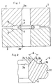
- FIG. 1 shows a first embodiment of fluid coupling of the invention.
- the fluid coupling 1 comprises first and second coupling members 2, 3 having respective fluid channels 2a, 3a communicating with each other, an annular gasket 4 interposed between abutting end faces of the two coupling members 2, 3 and screw means (not shown) for fastening the two coupling members 2, 3 together.
- the first and second coupling members 2, 3 are provided in the abutting end faces thereof with respective annular recessed portions 5, 6 each having a flat bottom face.
- the gasket 4 is disposed in a gasket enclosing space defined by the recessed portions 5, 6 of the two coupling members 2, 3.
- the gasket 4 is provided with an annular ridge 7 on each of opposite side surfaces thereof.
- the ridge 7 of the gasket 4 has a trapezoidal cross sectional shape defined by an outer tapered face 7a providing an outer peripheral surface, an inner tapered face 7b providing an inner peripheral surface and a flat face 7c providing a top end face.
- a face 7d extending radially outward from the base end of the outer tapered face 7a serves as a reference face for determining the height of the ridge 7.
- the distance from a plane through the center of the gasket 4 with respect to the axial direction thereof to the base end of the inner tapered face 7b is slightly smaller than the distance from the center plane through the gasket 4 to the reference face 7d (i.e., one half of the thickness of the gasket other than the ridge).
- the gasket 4 has an inside diameter (diameter of fluid channel) greater than the diameter of the fluid channels 2a, 3a of the two coupling members 2, 3.
- the axially opposite edges of the outer periphery of the gasket 4 are chamfered, and a cavity 7f having a circular-arc cross section is formed in the axial midportion of outer periphery of the gasket 4.
- the Vickers hardness HV of the gasket 4, the taper angle ⁇ between the tapered faces 7a, 7b of the ridge 7, the height P of the ridge 7 and the area S of the flat face 7c of the ridge 7 at the top end thereof are so determined that the value of thrust will be between a predetermined minimum value and a predetermined maximum value when the displacement due to tightening is altered according to the designing method to be described below.
- the two coupling members 2, 3 are about 300 in Vickers hardness HV.
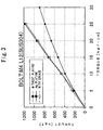
- FIG. 3 is a graph showing the relationship between the toque and the thrust.
- the graph shows the relationship between the torque and the thrust, as determined by tightening up coupling members in the form of blocks with four M4 bolts.
- Three kinds of bolts were used for the experiment; bolts without plating, bolts plated with silver, and bolts without plating and with application of grease. Use of these bolts indicates that the silver plating or grease reduces the friction involved in rotation, permitting the thrust to increase in proportion to the torque, and that in the case of the bolts without plating, the thrust increases at a smaller rate relative to the increase in the torque.
- a minimum tightening-up force is needed, that is, thrust of not smaller than a predetermined value is necessary for tightening up. Further to ensure the required strength, it is required that the thrust be not in excess of a predetermined value corresponding to the hardness of the gasket 4. Accordingly, when the factor of safety is also considered, it is preferred that the gasket 4 have such a hardness and shape (taper angle ⁇ , height P of the ridge and area S of flat top end face) as to satisfy the following expression: Minimum tightening-up force ⁇ safety factor ⁇ thrust for tightening-up the coupling ⁇ thrust corresponding to the surface hardness ⁇ safety factor.
- the minimum tightening-up force to be used is the greater of the two, i.e., the bolt load when the coupling is in use and the bolt load when the gasket is tightened up.
- Table 1 shows the mathematic expressions for calculating the minimum tightening-up force, etc. and the meanings of symbols.
- FIG. 5 shows a graph for use in obtaining gaskets suitable for use in the fluid coupling of the invention.
- the displacement is plotted as abscissa, the thrust or bolt load as ordinate, and the taper angle ⁇ of the ridges on the gasket is 90 deg to determine the relationship between the displacement and the thrust or bolt load.
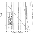
- FIGS. 6 and 7 show the results of experiments similar to that of FIG. 5, where the taper angle ⁇ of the gasket ridges 7 was 60 deg (FIG. 6) or 120 deg (FIG. 7).
- a comparison with FIG. 5 reveals that the change of the taper angle ⁇ from 90 deg to 60 deg results in a decrease in thrust, while the change of the taper angle ⁇ from 90 deg to 120 deg leads to an increase in thrust.
- a gasket 4 can be designed to obtain a predetermined value of thrust in a certain range by varying, for example, the Vickers hardness or taper angle.
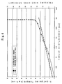
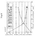
- FIG. 8 is another graph for use in obtaining gaskets 4 suitable for use in the fluid coupling of the invention.
- the displacement is plotted as abscissa, the thrust per unit area as ordinate, and the taper angle ⁇ of the ridges 7 on the gasket 4 is 90 deg to determine the relationship between the displacement and the thrust per unit area.
- the experimental values per unit area are the characteristics of the fluid coupling of the invention.
- the graph of FIG. 8 reveals that the thrust per unit area required for the sealing properties is obtained at a displacement of at least 0.1 mm, i.e., that the requirement that the surface pressure as determined from the minimum tightening-up force ⁇ the thrust per unit area for tightening up the coupling can be fulfilled.
- the sealing properties can be reliably obtained when the displacement is, for example, a least 0.15 mm. Further if the displacement is, for example, at least 0.4 mm, the thrust per unit area reaches the thrust level corresponding to a gasket Vickers hardness HV of 100, failing to fulfill the requirement, for assuring the fluid coupling 1 of strength, that the thrust per unit area for tightening up the coupling ⁇ thrust per unit area as determined from the Vickers hardness of the gasket. In view of the safety factor, therefore, it is desirable to obtain the strength on condition that the displacement should be up to 0.30 mm. Since the displacement corresponds to the height P of the ridges 7 of the gasket, the displacement, if determined, determines the height P of the ridges on the gasket 4.
- FIGS. 9 and 10 show the results obtained by conducting experiments similar to that of FIG. 8, with the ridges 7 of the gasket 4 given a taper angle ⁇ of 60 deg (FIG. 9) or 120 deg (FIG. 10).
- a compassion with FIG. 8 shows that that a change in the taper angle ⁇ from 90 deg to 60 deg gives rise to a need to increase the thrust per unit area, i.e., the thrust per unit area required for the sealing properties, hence a need to determine whether or not a design alteration is to be made at the same time to increase the height of the ridges for giving an increased displacement.
- the thrust per unit area i.e., the thrust per unit area required for the sealing properties
- the thrust per unit area can be smaller than when the taper angle ⁇ is 90 deg. It will then become necessary to determine whether a design alteration is to be made at the same time to increase the displacement by reducing the height of the ridges.
- the Vickers hardness HV is maintained at 100, the Vickers hardness can of course be altered; gaskets 4 which are further improved in both the sealing properties and durability can be designed by varying the Vickers hardness, taper angle, etc. by virtue of the increased freedom of design.
- the required Vickers hardness for example, of HV 100, can be obtained by fully subjecting the gasket 4 of stainless steel to a solid solution heat treatment, and the gasket 4 so treated is then polished to a mirror finish.
Landscapes
- Engineering & Computer Science (AREA)
- General Engineering & Computer Science (AREA)
- Mechanical Engineering (AREA)
- Gasket Seals (AREA)
- Flanged Joints, Insulating Joints, And Other Joints (AREA)
- Joints With Pressure Members (AREA)
Abstract
Description

Claims (5)
- A fluid coupling comprising a first and a second coupling member having respective fluid channels communicating with each other, a gasket interposed between abutting end faces of the two coupling members and screw means for fastening the two coupling members together, each of the first and second coupling members being provided in the end face thereof with an annular recessed portion having a flat bottom face, the gasket being annular and disposed within a space defined by the recessed portions of the two coupling members, the gasket having an annular ridge formed on each of opposite side surfaces thereof,
the fluid coupling being characterized in that the ridge of the gasket has a trapezoidal cross sectional shape defined by an outer tapered face providing an outer peripheral surface, an inner tapered face providing an inner peripheral surface and a flat face providing a top end surface. - A fluid coupling according to claim 1 wherein the hardness of the gasket, the angle between the tapered faces of the ridge, the height of the ridge and the area of the flat top end face of the ridge are so determined that the value of thrust for tightening up the coupling is between a predetermined minimum value and a predetermined maximum value.
- A fluid coupling according to claim 2 wherein the angle α between the outer tapered face of the annular ridge of the gasket and the inner tapered face thereof is 50 to 130 deg.
- A method of designing a fluid coupling comprising a first and a second coupling member having respective fluid channels communicating with each other, a gasket interposed between abutting end faces of the two coupling members and screw means for fastening the two coupling members together, each of the first and second coupling members being provided in the end face thereof with an annular recessed portion having a flat bottom face, the gasket being annular and disposed within a space defined by the recessed portions of the two coupling members, the gasket having an annular ridge formed on each of opposite side surfaces thereof,
the fluid coupling designing method being characterized in that the ridge of the gasket has a trapezoidal cross sectional shape defined by an outer tapered face providing an outer peripheral surface, an inner tapered face providing an inner peripheral surface and a flat face providing a top end surface, the hardness of the gasket, the angle between the tapered faces of the ridge, the height of the ridge and the area of the flat top end face of the ridge being so determined that the value of thrust for tightening up the coupling is between a predetermined minimum value and a predetermined maximum value. - A method of designing a fluid coupling according to claim 4 characterized in that the hardness of the gasket, the angle between the tapered faces of the ridge, the height of the ridge and the area of the flat top end face of the ridge are so determined as to satisfy the following expression:
Applications Claiming Priority (3)
| Application Number | Priority Date | Filing Date | Title |
|---|---|---|---|
| JP2002344877 | 2002-11-28 | ||
| JP2002344877A JP4560669B2 (en) | 2002-11-28 | 2002-11-28 | Fluid coupling and design method thereof |
| PCT/JP2003/013975 WO2004048836A1 (en) | 2002-11-28 | 2003-10-31 | Fluid coupling and method of designing the same |
Publications (2)
| Publication Number | Publication Date |
|---|---|
| EP1568931A1 true EP1568931A1 (en) | 2005-08-31 |
| EP1568931A4 EP1568931A4 (en) | 2007-11-28 |
Family
ID=32375975
Family Applications (1)
| Application Number | Title | Priority Date | Filing Date |
|---|---|---|---|
| EP03770065A Withdrawn EP1568931A4 (en) | 2002-11-28 | 2003-10-31 | Fluid coupling and method of designing the same |
Country Status (10)
| Country | Link |
|---|---|
| US (2) | US8083267B2 (en) |
| EP (1) | EP1568931A4 (en) |
| JP (1) | JP4560669B2 (en) |
| KR (1) | KR101079446B1 (en) |
| CN (1) | CN100406799C (en) |
| AU (1) | AU2003280668A1 (en) |
| CA (1) | CA2507433A1 (en) |
| IL (1) | IL168767A (en) |
| TW (1) | TWI314977B (en) |
| WO (1) | WO2004048836A1 (en) |
Families Citing this family (18)
| Publication number | Priority date | Publication date | Assignee | Title |
|---|---|---|---|---|
| KR101230671B1 (en) * | 2008-04-22 | 2013-02-07 | 가부시키가이샤 후지킨 | Fluid coupling and retainer for fluid coupling |
| CA2771878C (en) * | 2009-08-26 | 2017-08-08 | Toki Engineering Co., Ltd. | Metal seal ring and conduit device using metal seal ring |
| JP5334769B2 (en) * | 2009-09-10 | 2013-11-06 | 独立行政法人物質・材料研究機構 | High strength bolt |
| US8628095B2 (en) * | 2010-05-17 | 2014-01-14 | GM Global Technology Operations LLC | Gasket for a pressurized fluid interface |
| US9074686B2 (en) | 2010-12-06 | 2015-07-07 | Microflex Technologies Llc | Ring seal retainer assembly and methods |
| JP2014169770A (en) * | 2013-03-05 | 2014-09-18 | Nok Corp | Seal ring |
| WO2015179155A1 (en) * | 2014-05-19 | 2015-11-26 | Microflex Technologies Llc | Ring seal with sealing surface extension |
| JP2019019834A (en) * | 2017-07-11 | 2019-02-07 | 株式会社ピュアロンジャパン | gasket |
| JP6913009B2 (en) * | 2017-11-28 | 2021-08-04 | 熊本県 | Metal seal, fluid control device and sealing method |
| JP6847075B2 (en) * | 2018-03-30 | 2021-03-24 | 日本ピラー工業株式会社 | Gasket and flow path joint structure |
| JP6847074B2 (en) * | 2018-03-30 | 2021-03-24 | 日本ピラー工業株式会社 | Gasket and flow path joint structure |
| US20210054932A1 (en) * | 2018-03-30 | 2021-02-25 | Nippon Pillar Packing Co., Ltd. | Gasket and flow passage connector structure |
| JP7382150B2 (en) * | 2019-03-25 | 2023-11-16 | エドワーズ株式会社 | Vacuum pumps and seal members used in vacuum pumps |
| CN110159760A (en) * | 2019-04-29 | 2019-08-23 | 海洋王照明科技股份有限公司 | Sealing element, end face seal structure and lamps and lanterns |
| CN116324234B (en) * | 2020-10-20 | 2025-11-25 | 株式会社华尔卡 | Metal gasket |
| KR20230148242A (en) * | 2021-02-24 | 2023-10-24 | 마이크로플렉스 테크놀로지스 아이엔씨. | Ring seal compatible with multiple port types |
| AU2023267532A1 (en) * | 2022-05-10 | 2024-11-21 | Frederick Rezaei | System and method for sealing a fluid pathway |
| TW202513995A (en) | 2023-08-01 | 2025-04-01 | 美商微伸科技股份有限公司 | Ring seal with trough |
Family Cites Families (32)
| Publication number | Priority date | Publication date | Assignee | Title |
|---|---|---|---|---|
| US323731A (en) * | 1885-08-04 | Geoege b | ||
| US2050137A (en) * | 1933-12-23 | 1936-08-04 | United Superior Union Company | Plumber's union and method of manufacture thereof |
| DE731042C (en) * | 1936-08-25 | 1943-02-01 | Karl Peter May | Connection for pipes and other hollow bodies with two different types of seals connected in series |
| US3090630A (en) * | 1960-01-07 | 1963-05-21 | Autoclave Eng Inc | High pressure joint |
| FR1583060A (en) * | 1968-05-14 | 1969-10-17 | ||
| US3479063A (en) * | 1968-12-24 | 1969-11-18 | Flexfloat Eng Co | Fluid pressure tightened joint |
| US4294477A (en) * | 1977-06-08 | 1981-10-13 | Vetco Inc. | Flexible ring gasket retainer for flanged connectors |
| JPS55115659A (en) * | 1979-02-26 | 1980-09-05 | Babcock Hitachi Kk | Leakproof container |
| JPS56166578A (en) | 1980-05-27 | 1981-12-21 | Tokyo Electric Co Ltd | Electronic cash register |
| JPS5872560A (en) | 1981-10-27 | 1983-04-30 | Teikoku Chem Ind Corp Ltd | Indomethacin phenyl ester derivative |
| JPS5872560U (en) * | 1981-11-10 | 1983-05-17 | エヌオーケー株式会社 | gasket |
| JPS5934487A (en) | 1982-08-23 | 1984-02-24 | Hitachi Ltd | Ignition system for internal combustion engine |
| US4407516A (en) * | 1982-12-13 | 1983-10-04 | Acf Industries, Incorporated | Pressure energized sealing connection with annular seal ring |
| JPS60147886A (en) | 1984-01-13 | 1985-08-03 | Komatsu Ltd | Recognition method for continuity of profile line |
| JPS60147886U (en) * | 1984-03-10 | 1985-10-01 | 日本ピラ−工業株式会社 | insulation gasket |
| DE3509136A1 (en) * | 1985-03-14 | 1986-09-18 | Elring Dichtungswerke Gmbh, 7012 Fellbach | Cylinder head gasket |
| US4813838A (en) * | 1985-09-27 | 1989-03-21 | Trace Products, Inc. | Automatic loader for computer diskettes |
| DE3909424C2 (en) * | 1989-03-22 | 1997-06-05 | Walterscheid Gmbh Gkn | Swivel screw connection |
| JPH03209067A (en) * | 1990-01-10 | 1991-09-12 | Eagle Ind Co Ltd | Saw-teeth form metal gasket and its manufacture |
| CA2131803A1 (en) * | 1992-03-12 | 1993-09-16 | John Stobbart | Seal ring and joint |
| US5209522A (en) * | 1992-04-13 | 1993-05-11 | Oceaneering International, Inc. | Anti-extrusion apparatus for an inwardly compressed seal |
| JP3053728B2 (en) * | 1993-12-22 | 2000-06-19 | ダイハツ工業株式会社 | Exhaust pipe connection structure |
| JPH07233887A (en) * | 1993-12-27 | 1995-09-05 | Nikkiso Co Ltd | Annular sealing member and flange |
| JP3517719B2 (en) * | 1995-05-18 | 2004-04-12 | 忠弘 大見 | Pipe fittings |
| JPH11173476A (en) | 1997-12-15 | 1999-06-29 | Sekisui Chem Co Ltd | Packing for flange connection |
| US6357759B1 (en) * | 1999-02-15 | 2002-03-19 | Mitsubishi Cable Industries, Ltd. | Jacket seal |
| JP3346756B2 (en) * | 1999-02-15 | 2002-11-18 | 三菱電線工業株式会社 | Jacket seal |
| US6409180B1 (en) * | 2000-04-21 | 2002-06-25 | Perkinelmer, Inc. | Metallic seal |
| US6357760B1 (en) * | 2000-05-19 | 2002-03-19 | Michael Doyle | Ring seal |
| JP2003194225A (en) * | 2001-12-28 | 2003-07-09 | Nichias Corp | Metal gasket |
| AU2003211159A1 (en) * | 2002-02-20 | 2003-09-09 | Garlock Sealing Technologies Llc | Metal seal and retainer |
| JP4556205B2 (en) * | 2003-03-28 | 2010-10-06 | ニチアス株式会社 | Metal gasket |
-
2002
- 2002-11-28 JP JP2002344877A patent/JP4560669B2/en not_active Expired - Fee Related
-
2003
- 2003-10-31 CA CA002507433A patent/CA2507433A1/en not_active Abandoned
- 2003-10-31 EP EP03770065A patent/EP1568931A4/en not_active Withdrawn
- 2003-10-31 US US10/536,036 patent/US8083267B2/en not_active Expired - Fee Related
- 2003-10-31 CN CN2003801006880A patent/CN100406799C/en not_active Expired - Fee Related
- 2003-10-31 WO PCT/JP2003/013975 patent/WO2004048836A1/en not_active Ceased
- 2003-10-31 AU AU2003280668A patent/AU2003280668A1/en not_active Abandoned
- 2003-10-31 KR KR1020057005730A patent/KR101079446B1/en not_active Expired - Fee Related
- 2003-11-26 TW TW092133119A patent/TWI314977B/en not_active IP Right Cessation
-
2005
- 2005-05-24 IL IL168767A patent/IL168767A/en not_active IP Right Cessation
-
2008
- 2008-06-26 US US12/213,925 patent/US8256115B2/en not_active Expired - Fee Related
Also Published As
| Publication number | Publication date |
|---|---|
| KR101079446B1 (en) | 2011-11-02 |
| US8256115B2 (en) | 2012-09-04 |
| TWI314977B (en) | 2009-09-21 |
| CA2507433A1 (en) | 2004-06-10 |
| US20090015010A1 (en) | 2009-01-15 |
| TW200422550A (en) | 2004-11-01 |
| AU2003280668A1 (en) | 2004-06-18 |
| WO2004048836A1 (en) | 2004-06-10 |
| IL168767A (en) | 2009-02-11 |
| CN1692245A (en) | 2005-11-02 |
| CN100406799C (en) | 2008-07-30 |
| KR20050084835A (en) | 2005-08-29 |
| JP2004176835A (en) | 2004-06-24 |
| US20060055122A1 (en) | 2006-03-16 |
| US8083267B2 (en) | 2011-12-27 |
| EP1568931A4 (en) | 2007-11-28 |
| JP4560669B2 (en) | 2010-10-13 |
Similar Documents
| Publication | Publication Date | Title |
|---|---|---|
| US20090015010A1 (en) | Method of making a fluid coupling | |
| US10422429B2 (en) | Ultra-seal gasket for joining high purity fluid pathways | |
| US9797513B2 (en) | Annular sealing device | |
| US3760921A (en) | Clutch disc and method of making | |
| JPH02290637A (en) | Manufacture of clutch with sintered friction lining or friction ring for brake | |
| EP2684281A2 (en) | Separating can of a magnetic coupling, in particular of a magnetic coupling pump | |
| KR100987747B1 (en) | High pressure sealing device | |
| EP0790425A1 (en) | Constant velocity universal joint | |
| JP6447667B2 (en) | Seal ring and sealing structure | |
| US20050001428A1 (en) | Anchor ring | |
| EP2068051A1 (en) | Gasket | |
| JP7128500B2 (en) | Washer fastening structure | |
| JPH09264427A (en) | Metal gasket | |
| JPH0772574B2 (en) | Grooved clutch plate for limited slip differential | |
| JP2013072549A (en) | Metal gasket | |
| CN118463881A (en) | Measuring probe and method for producing a measuring probe | |
| JP2024113600A (en) | Ring-shaped metal gasket | |
| JP2001004028A (en) | Metal gasket | |
| JPH086754B2 (en) | High torque transmission shaft | |
| KR20040010646A (en) | Oil ring for an internal combustion engine | |
| HK1228985A1 (en) | Ultra-seal gasket for joining high purity fluid pathways |
Legal Events
| Date | Code | Title | Description |
|---|---|---|---|
| PUAI | Public reference made under article 153(3) epc to a published international application that has entered the european phase |
Free format text: ORIGINAL CODE: 0009012 |
|
| 17P | Request for examination filed |
Effective date: 20050530 |
|
| AK | Designated contracting states |
Kind code of ref document: A1 Designated state(s): AT BE BG CH CY CZ DE DK EE ES FI FR GB GR HU IE IT LI LU MC NL PT RO SE SI SK TR |
|
| AX | Request for extension of the european patent |
Extension state: AL LT LV MK |
|
| DAX | Request for extension of the european patent (deleted) | ||
| RBV | Designated contracting states (corrected) |
Designated state(s): CH DE FR GB IT LI NL |
|
| A4 | Supplementary search report drawn up and despatched |
Effective date: 20071029 |
|
| 17Q | First examination report despatched |
Effective date: 20090205 |
|
| STAA | Information on the status of an ep patent application or granted ep patent |
Free format text: STATUS: THE APPLICATION IS DEEMED TO BE WITHDRAWN |
|
| 18D | Application deemed to be withdrawn |
Effective date: 20090615 |