EP1568903A1 - Amortisseur en matériau élastomère pour biellette de suspension ou autre organe de liaison - Google Patents
Amortisseur en matériau élastomère pour biellette de suspension ou autre organe de liaison Download PDFInfo
- Publication number
- EP1568903A1 EP1568903A1 EP05101431A EP05101431A EP1568903A1 EP 1568903 A1 EP1568903 A1 EP 1568903A1 EP 05101431 A EP05101431 A EP 05101431A EP 05101431 A EP05101431 A EP 05101431A EP 1568903 A1 EP1568903 A1 EP 1568903A1
- Authority
- EP
- European Patent Office
- Prior art keywords
- head
- damper
- face
- connecting member
- elements
- Prior art date
- Legal status (The legal status is an assumption and is not a legal conclusion. Google has not performed a legal analysis and makes no representation as to the accuracy of the status listed.)
- Granted
Links
- 239000013536 elastomeric material Substances 0.000 title claims abstract description 4
- 210000005069 ears Anatomy 0.000 claims description 11
- 239000006096 absorbing agent Substances 0.000 claims description 10
- 230000035939 shock Effects 0.000 claims description 10
- 238000013016 damping Methods 0.000 claims description 8
- 238000000034 method Methods 0.000 claims description 4
- 239000000725 suspension Substances 0.000 abstract description 9
- 210000004417 patella Anatomy 0.000 description 10
- 239000004744 fabric Substances 0.000 description 5
- 210000000056 organ Anatomy 0.000 description 4
- 230000001133 acceleration Effects 0.000 description 2
- 230000015556 catabolic process Effects 0.000 description 2
- 238000006731 degradation reaction Methods 0.000 description 2
- 238000006073 displacement reaction Methods 0.000 description 2
- 229920001971 elastomer Polymers 0.000 description 2
- 239000000806 elastomer Substances 0.000 description 2
- 239000000463 material Substances 0.000 description 2
- 239000000126 substance Substances 0.000 description 2
- 239000000853 adhesive Substances 0.000 description 1
- 230000001070 adhesive effect Effects 0.000 description 1
- 230000000052 comparative effect Effects 0.000 description 1
- 238000002788 crimping Methods 0.000 description 1
- 230000000694 effects Effects 0.000 description 1
- 238000001914 filtration Methods 0.000 description 1
- 239000012530 fluid Substances 0.000 description 1
- 229920005560 fluorosilicone rubber Polymers 0.000 description 1
- 239000000446 fuel Substances 0.000 description 1
- 238000009434 installation Methods 0.000 description 1
- 239000003350 kerosene Substances 0.000 description 1
- 238000005461 lubrication Methods 0.000 description 1
- 239000002184 metal Substances 0.000 description 1
- 239000000203 mixture Substances 0.000 description 1
- 238000000465 moulding Methods 0.000 description 1
- 239000003921 oil Substances 0.000 description 1
Images

Classifications
-
- F—MECHANICAL ENGINEERING; LIGHTING; HEATING; WEAPONS; BLASTING
- F16—ENGINEERING ELEMENTS AND UNITS; GENERAL MEASURES FOR PRODUCING AND MAINTAINING EFFECTIVE FUNCTIONING OF MACHINES OR INSTALLATIONS; THERMAL INSULATION IN GENERAL
- F16C—SHAFTS; FLEXIBLE SHAFTS; ELEMENTS OR CRANKSHAFT MECHANISMS; ROTARY BODIES OTHER THAN GEARING ELEMENTS; BEARINGS
- F16C11/00—Pivots; Pivotal connections
- F16C11/04—Pivotal connections
- F16C11/06—Ball-joints; Other joints having more than one degree of angular freedom, i.e. universal joints
- F16C11/0614—Ball-joints; Other joints having more than one degree of angular freedom, i.e. universal joints the female part of the joint being open on two sides
-
- F—MECHANICAL ENGINEERING; LIGHTING; HEATING; WEAPONS; BLASTING
- F16—ENGINEERING ELEMENTS AND UNITS; GENERAL MEASURES FOR PRODUCING AND MAINTAINING EFFECTIVE FUNCTIONING OF MACHINES OR INSTALLATIONS; THERMAL INSULATION IN GENERAL
- F16C—SHAFTS; FLEXIBLE SHAFTS; ELEMENTS OR CRANKSHAFT MECHANISMS; ROTARY BODIES OTHER THAN GEARING ELEMENTS; BEARINGS
- F16C11/00—Pivots; Pivotal connections
- F16C11/04—Pivotal connections
- F16C11/045—Pivotal connections with at least a pair of arms pivoting relatively to at least one other arm, all arms being mounted on one pin
-
- F—MECHANICAL ENGINEERING; LIGHTING; HEATING; WEAPONS; BLASTING
- F16—ENGINEERING ELEMENTS AND UNITS; GENERAL MEASURES FOR PRODUCING AND MAINTAINING EFFECTIVE FUNCTIONING OF MACHINES OR INSTALLATIONS; THERMAL INSULATION IN GENERAL
- F16C—SHAFTS; FLEXIBLE SHAFTS; ELEMENTS OR CRANKSHAFT MECHANISMS; ROTARY BODIES OTHER THAN GEARING ELEMENTS; BEARINGS
- F16C27/00—Elastic or yielding bearings or bearing supports, for exclusively rotary movement
- F16C27/06—Elastic or yielding bearings or bearing supports, for exclusively rotary movement by means of parts of rubber or like materials
- F16C27/063—Sliding contact bearings
-
- F—MECHANICAL ENGINEERING; LIGHTING; HEATING; WEAPONS; BLASTING
- F16—ENGINEERING ELEMENTS AND UNITS; GENERAL MEASURES FOR PRODUCING AND MAINTAINING EFFECTIVE FUNCTIONING OF MACHINES OR INSTALLATIONS; THERMAL INSULATION IN GENERAL
- F16C—SHAFTS; FLEXIBLE SHAFTS; ELEMENTS OR CRANKSHAFT MECHANISMS; ROTARY BODIES OTHER THAN GEARING ELEMENTS; BEARINGS
- F16C7/00—Connecting-rods or like links pivoted at both ends; Construction of connecting-rod heads
- F16C7/02—Constructions of connecting-rods with constant length
-
- F—MECHANICAL ENGINEERING; LIGHTING; HEATING; WEAPONS; BLASTING
- F16—ENGINEERING ELEMENTS AND UNITS; GENERAL MEASURES FOR PRODUCING AND MAINTAINING EFFECTIVE FUNCTIONING OF MACHINES OR INSTALLATIONS; THERMAL INSULATION IN GENERAL
- F16C—SHAFTS; FLEXIBLE SHAFTS; ELEMENTS OR CRANKSHAFT MECHANISMS; ROTARY BODIES OTHER THAN GEARING ELEMENTS; BEARINGS
- F16C2326/00—Articles relating to transporting
- F16C2326/43—Aeroplanes; Helicopters
-
- F—MECHANICAL ENGINEERING; LIGHTING; HEATING; WEAPONS; BLASTING
- F16—ENGINEERING ELEMENTS AND UNITS; GENERAL MEASURES FOR PRODUCING AND MAINTAINING EFFECTIVE FUNCTIONING OF MACHINES OR INSTALLATIONS; THERMAL INSULATION IN GENERAL
- F16C—SHAFTS; FLEXIBLE SHAFTS; ELEMENTS OR CRANKSHAFT MECHANISMS; ROTARY BODIES OTHER THAN GEARING ELEMENTS; BEARINGS
- F16C2360/00—Engines or pumps
- F16C2360/23—Gas turbine engines
-
- Y—GENERAL TAGGING OF NEW TECHNOLOGICAL DEVELOPMENTS; GENERAL TAGGING OF CROSS-SECTIONAL TECHNOLOGIES SPANNING OVER SEVERAL SECTIONS OF THE IPC; TECHNICAL SUBJECTS COVERED BY FORMER USPC CROSS-REFERENCE ART COLLECTIONS [XRACs] AND DIGESTS
- Y10—TECHNICAL SUBJECTS COVERED BY FORMER USPC
- Y10T—TECHNICAL SUBJECTS COVERED BY FORMER US CLASSIFICATION
- Y10T403/00—Joints and connections
- Y10T403/32—Articulated members
- Y10T403/32606—Pivoted
- Y10T403/32631—Universal ball and socket
-
- Y—GENERAL TAGGING OF NEW TECHNOLOGICAL DEVELOPMENTS; GENERAL TAGGING OF CROSS-SECTIONAL TECHNOLOGIES SPANNING OVER SEVERAL SECTIONS OF THE IPC; TECHNICAL SUBJECTS COVERED BY FORMER USPC CROSS-REFERENCE ART COLLECTIONS [XRACs] AND DIGESTS
- Y10—TECHNICAL SUBJECTS COVERED BY FORMER USPC
- Y10T—TECHNICAL SUBJECTS COVERED BY FORMER US CLASSIFICATION
- Y10T403/00—Joints and connections
- Y10T403/32—Articulated members
- Y10T403/32606—Pivoted
- Y10T403/32861—T-pivot, e.g., wrist pin, etc.
- Y10T403/32918—T-pivot, e.g., wrist pin, etc. fork and tongue
- Y10T403/32926—T-pivot, e.g., wrist pin, etc. fork and tongue with interposed antifriction means
Definitions
- the present invention relates to a damping element for a body of link, such as a link, provided with a flat head, mounted by via a ball joint on an axis integral with a female clevis.
- the Function of the element is to dampen the vibrations between the head and the clevis.
- the invention aims in particular a suspension link of a module such that the housing enclosing the gears for the drive of the machines accessories on a gas turbine engine applied to the field aeronautics.
- a gas turbine engine used for the propulsion of aircraft, a turbojet engine in particular, includes auxiliary machinery necessary for its operation. These are, for example, fluid pumps for actuate control, lubrication or fuel than electric generators. These machines are in mesh mechanical with a gearbox which is itself connected to a tree motor by a suitable mechanical connection. This case is commonly known by its acronym, AGB for "Accessory Gear Box", in the field.
- the gearbox is kept in suspension on the crankcase a little downstream of the blower stage by means of which are in the form of rods.
- a link comprises a rod terminated at both ends by a head of flat shape, with two parallel faces, in the bore of which a cage cylindrical on the outside is held by crimping.
- the internal surface the cage serves as a guide to a socket with spherical outer surfaces forming a patella.
- Self-lubricating fabric is glued inside the cage and stays in contact with the spherical surface of the patella to allow the relative movements between them. This fabric makes it possible to absorb the phenomena vibratory by an assembly without play with a couple rotulant.
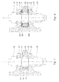
- Each link head 10 is mounted between the ears 21 and 23 of a female clevis 20 as shown in Figure 1.
- the head comprises two parallel faces 11 and 12 pierced by a bore for the housing of the cage 13 with its patella 14.
- the self-lubricating fabric is not represented.
- the head is held between the two ears of the clevis by a screw 30 which passes through these and the patella.
- the screw is itself immobilized by a nut 33.
- the rod is immobilized axially in the direction of the screw 30 by the patella which as seen in the figure is supported on one side against the inner face of the ear 23 of the yoke and the other against a shoulder 35 of the screw. Thanks to this mounting with ball joint, the rod head can rotate freely around the axis of the screw and around any axis perpendicular to this one within the limits of the stops defined by the environment. The movement is limited in particular according to the interval, provided on both sides, between the tie-rod head and the ears of the clevis.
- this link is subjected to micro-displacements due to vibration forces, in particular directed stresses parallel to the axis of the screw, in particular because of the low inclination links relative to the horizontal plane.
- vibration forces in particular directed stresses parallel to the axis of the screw, in particular because of the low inclination links relative to the horizontal plane.
- These solicitations end at the long wear and degrade the self-lubricating fabric between the patella and the cage. This results in contact and damage to the metal surfaces require repair intervention.
- the invention aims at the development of a damping means vibrations between the link head and the ears of the clevis which she is mounted.
- the subject of the invention is a damping means for vibrations between a connecting member mounted with a ball joint between the two ears of a screed.
- the object of the invention is therefore a means of damping the organ of liaison which is implemented and which significantly increases the life of the assembly rotulant.
- a damping material is made elastomer for a connecting member, such as a rod, said member comprising a head with two faces parallel to each other and a bore forming a housing for a ball joint with its cage, characterized in that that it comprises two disc-shaped elements, parallel to one another, each with central opening wide enough not to cover the portions of the patella projecting from the head and connected at their periphery by means of connection.
- the discs have a thickness at less equal to the portion of the ball protruding from one side of the head. This arrangement makes it possible to compress a disk at the screw in the screed. In operation, the other disc comes at least also in contact with its adjacent surface and is compressed when the link is tilted. This principle allows a effective damping of vibrations and prevents contact between the head of the connecting member and the ears of the clevis.
- the thicknesses of the two disks identical are identical,
- the two thicknesses are different.
- said linking means are formed by a plurality of arms.
- said linking means are formed by a plurality of arms.
- they allow a adaptability of the same damper to several types of geometry and of these. If necessary we adapt the number and the dimension arms at the geometry and the connecting member used.
- the discs are also adapted to the geometry and diameter of the organ link. This arrangement allows easy mounting of the damper, both discs that can be moved apart easily and effortlessly.
- the invention also relates to a method for mounting a damper on a connecting member, such as a link, supported by an axis between the ears a female clevis.
- a connecting member such as a link
- the head of the connecting member being free, we slide the damper around the head in such a way that the two disc-shaped elements each come against a face of the so-called head, we introduce the head with the damper between the ears of the screed and the connecting member is locked in the yoke with said axis.
- the interval between each face and the adjacent ear being different, the damper having a more thick than the other, we place the thicker element between the face and the ear with the largest interval.
- the invention also aims at a damping system for an organ of link mounted on a clevis with two ears including a damper such than presented above between each face and the ear facing it.
- the damper 100 is composed a first 101 and a second 103 disk-shaped elements. These two elements 101 and 103 have a circular central opening, 101 'and 103' respectively. They are connected to each other on their periphery by axial connecting means, here by six arms 110, 111, 112, 113, 114 and 115 which keep them at a fixed distance.
- the arms are arranged way to allow the installation of the shock absorber on the head of the organ link.
- the elements and the connecting means have come molding in the same material.
- the latter is an elastomer whose the chemical composition is adapted to the vibration filtering function but also to the environment in which it is placed.
- a fluorosilicone elastomer is suitable for the application to the suspension of the AGB boxes of a turbojet engine.
- FIG. 3 Shown in FIG. 3 is the shock absorber in place on the head of the connecting member before the latter is mounted on the yoke.
- the elements 101 and 103 are each applied to a face 11 or 12 of the head 10.
- the arms 110 to 115 maintain the place both on the head. It is observed that the orifices 101 'and 103' are wide enough not to cover the patella projecting from both sides of the head 10.
- the thickness of the elements 101 and 103 is for the ball 14 is not protruding compared to the plans of elements 101 and 103.
- test conditions were as follows.
- the fastening of the links was representative of the fixings on the motor: clevis, pins, nuts.
- test results are as follows: for A there is a beginning wear of the ball joint resulting in a loss of the torque due to the degradation of the self-lubricating fabric by the effect of micro-displacements, and a start of play between the ball and the cage. For B we see a no change in the mechanical behavior of the patella during any endurance. These results show that the holding of the rods of suspension in vibratory endurance is not degraded but significantly improved.
Landscapes
- Engineering & Computer Science (AREA)
- General Engineering & Computer Science (AREA)
- Mechanical Engineering (AREA)
- Pivots And Pivotal Connections (AREA)
- Vibration Prevention Devices (AREA)
- Vibration Dampers (AREA)
- Springs (AREA)
- Fluid-Damping Devices (AREA)
Abstract
Description
- une endurance pendant 5×10⁷ cycles à une fréquence de 2000 Hz avec une accélération de 25g, appliquée dans le sens axial de la rotule,
- une endurance pendant 7,2×10⁷ cycles sur la fréquence propre de la biellette sur le mode 1F (1200Hz) à une accélération de niveau 25g, appliquée dans le sens axial de la rotule.
Claims (8)
- Amortisseur en matériau élastomère pour un organe de liaison, tel qu'une biellette ledit organe comprenant une tête (10) avec deux faces (11, 12) parallèles entre elles et traversée par un alésage formant un logement pour une rotule (14) avec sa cage (13), caractérisé par le fait qu'il comprend deux éléments (101, 103) en forme de disque, parallèles entre eux, chacun avec une ouverture centrale suffisamment large pour ne pas recouvrir les portions de la rotule faisant saillie par rapport à la tête et reliés à leur périphérie par des moyens de liaison (110, 111, 112, 113, 114, 115).
- Amortisseur selon la revendication précédente dont les éléments (101, 103) en forme de disque ont une épaisseur au moins égale à la portion de la rotule (14) en saillie par rapport à une face de la tête.
- Amortisseur selon l'une des revendications précédentes dont les épaisseurs desdits deux éléments '101,103) sont identiques
- Amortisseur selon l'une des revendications 1 et 2 dont les épaisseurs desdits deux éléments (101, 103) sont différentes.
- Amortisseur selon l'une des revendications précédentes dont les dits moyens de liaison sont formés par une pluralité de bras (110, 111, 112, 113, 114, 115).
- Procédé pour monter un amortisseur selon l'une des revendications précédentes sur un organe de liaison, tel qu'une biellette, supporté par un axe (30) entre les oreilles (21, 23) d'une chape femelle (20), selon lequel la tête (10) de l'organe étant libre on glisse l'amortisseur (100) autour de la tête de telle façon que les deux éléments (101, 103) en forme de disque viennent chacun contre une face de la dite tête (10), on introduit la tête avec l'amortisseur (100) entre les oreilles (21, 23) de la chape et on bloque l'organe de liaison dans la chape (20) avec ledit axe.
- Procédé selon la revendication précédente, le jeu entre chaque face (11, 12) de la tête (10) et l'oreille adjacente étant différent, l'amortisseur (100) présentant un élément (101, 103) plus épais que l'autre, on place l'élément plus épais entre la face et l'oreille présentant entre eux le jeu le plus grand.
- Système d'amortissement pour un organe de liaison (10) monté sur une chape (20) à deux oreilles (21, 23) comprenant un amortisseur (10) selon l'une des revendications 1 à 5, entre chaque face de l'organe de liaison et l'oreille qui fait face à celle-ci.
Applications Claiming Priority (2)
| Application Number | Priority Date | Filing Date | Title |
|---|---|---|---|
| FR0401867 | 2004-02-25 | ||
| FR0401867A FR2866683B1 (fr) | 2004-02-25 | 2004-02-25 | Amortisseur en materiau elastomere pour biellette de suspension ou autre organe de liaison |
Publications (2)
| Publication Number | Publication Date |
|---|---|
| EP1568903A1 true EP1568903A1 (fr) | 2005-08-31 |
| EP1568903B1 EP1568903B1 (fr) | 2008-10-01 |
Family
ID=34746436
Family Applications (1)
| Application Number | Title | Priority Date | Filing Date |
|---|---|---|---|
| EP05101431A Expired - Lifetime EP1568903B1 (fr) | 2004-02-25 | 2005-02-24 | Ensemble comportant un organe de liaison et un amortisseur en matériau élastomère |
Country Status (10)
| Country | Link |
|---|---|
| US (1) | US8002489B2 (fr) |
| EP (1) | EP1568903B1 (fr) |
| JP (1) | JP4959947B2 (fr) |
| CN (1) | CN100557264C (fr) |
| CA (1) | CA2498259C (fr) |
| DE (1) | DE602005009985D1 (fr) |
| ES (1) | ES2315793T3 (fr) |
| FR (1) | FR2866683B1 (fr) |
| RU (1) | RU2389921C2 (fr) |
| UA (1) | UA84134C2 (fr) |
Cited By (3)
| Publication number | Priority date | Publication date | Assignee | Title |
|---|---|---|---|---|
| WO2014154980A1 (fr) | 2013-03-29 | 2014-10-02 | Snecma | Dispositif d'articulation à rotule pour la suspension d'une turbomachine a un pylone ou la suspension d'un equipement au corps de la turbomachine. |
| EP3453901A1 (fr) * | 2017-09-08 | 2019-03-13 | United Technologies Corporation | Ensemble de liaison |
| CN116750229A (zh) * | 2023-08-21 | 2023-09-15 | 成都金支点科技有限公司 | 一种微型无人机动力系统隔振装置及微型无人机 |
Families Citing this family (29)
| Publication number | Priority date | Publication date | Assignee | Title |
|---|---|---|---|---|
| JP2007177880A (ja) * | 2005-12-27 | 2007-07-12 | Minebea Co Ltd | 球面軸受及び該球面軸受を備えたロードセルの振れ止め装置 |
| DE07750434T1 (de) | 2007-02-09 | 2010-01-28 | Bell Helicopter Textron, Inc., Fort Worth | Selbsthaltende drehsicherungsklemme |
| US8806972B2 (en) * | 2007-05-03 | 2014-08-19 | T-Motion Technology Co., Ltd. | Telescoping rod structure for linear actuator |
| GB0913913D0 (en) * | 2009-08-10 | 2009-09-16 | Airbus Operations Ltd | Pinned lug joint |
| PL2390180T3 (pl) * | 2010-05-27 | 2013-06-28 | Agustawestland Spa | Nie-obracane złącze uniwersalne do jednostki napędowej helikoptera |
| EP2587003A1 (fr) | 2011-10-25 | 2013-05-01 | Siemens Aktiengesellschaft | Ensemble formant support de moteur à turbine à gaz |
| US9272781B2 (en) * | 2011-11-01 | 2016-03-01 | Textron Innovations Inc. | Rotor system anti-rotation wear protector |
| FR2982331B1 (fr) * | 2011-11-07 | 2013-11-29 | Eurocopter France | Mecanisme d'articulation en rotule entre une chape et une bielle, notamment pour un appareillage de commande equipant un giravion |
| US20140030069A1 (en) * | 2012-07-26 | 2014-01-30 | Jonathan D. Little | Top hat bearing retainer for variable vane actuator |
| AU2013204393A1 (en) * | 2012-08-27 | 2014-03-13 | Bradken Resources Pty Limited | Dragline rigging components |
| CN105517896B (zh) | 2013-09-05 | 2018-04-13 | 空中客车营运有限公司 | 起落架驱动系统柔性接合装置 |
| CA2921136A1 (fr) | 2013-09-05 | 2015-03-12 | Airbus Operations Limited | Interface souple de systeme d'entrainement de train d'atterrissage |
| US9556902B2 (en) * | 2013-11-07 | 2017-01-31 | Cnh Industrial America Llc | Agricultural tandem pivot assembly |
| US9278752B2 (en) * | 2014-03-17 | 2016-03-08 | Lockheed Martin Corporation | Apparatus and system for preventing wear to a component |
| US9656744B2 (en) * | 2014-05-21 | 2017-05-23 | Bell Helicopter Textron Inc. | Adjustable blade-to-hub lead-lag damper attachment |
| US10520012B1 (en) * | 2015-04-14 | 2019-12-31 | Roller Bearing Company Of America, Inc. | Rod end having wear mitigation features for an augmenter nozzle on a jet engine turbine |
| US10024270B2 (en) * | 2015-10-13 | 2018-07-17 | Rohr, Inc. | Vibration damping drag link fitting for a thrust reverser |
| US10598211B2 (en) | 2016-05-23 | 2020-03-24 | United Technologies Corporation | Spherical bearing sleeve configured with one or more discrete collars |
| US10570950B2 (en) * | 2016-05-23 | 2020-02-25 | United Technologies Corporation | Spherical joint assembly with a spherical bearing between integral collars |
| US10911678B2 (en) * | 2016-09-16 | 2021-02-02 | Gopro, Inc. | Vibration damping gimbal sleeve for an aerial vehicle |
| DE102016226036A1 (de) * | 2016-12-22 | 2018-06-28 | Bosch Mahle Turbo Systems Gmbh & Co. Kg | Ladeeinrichtung |
| FR3062440B1 (fr) * | 2017-02-02 | 2019-03-15 | Safran Transmission Systems | Palier lisse de turbomachine a filtre integre et son procede de realisation |
| FR3062438B1 (fr) * | 2017-02-02 | 2019-03-22 | Safran Transmission Systems | Bielle de turbomachine a filtre integre et son procede de realisation |
| RU191370U1 (ru) * | 2019-06-14 | 2019-08-02 | Федеральное государственное автономное образовательное учреждение высшего образования "Южно-Уральский государственный университет (национальный исследовательский университет)" ФГАОУ ВО "ЮУрГУ (НИУ)" | Самоустанавливающаяся роторная система электромашины с коническими газостатическими подшипниками |
| FR3103176B1 (fr) * | 2019-11-15 | 2022-08-19 | Airbus Operations Sas | Attache moteur pour un moteur d’un aeronef comportant une bielle et un systeme de protection de la bielle |
| US12129887B2 (en) * | 2021-10-24 | 2024-10-29 | Textron Innovations Inc. | Self-retaining wear-pad leveler |
| CN115890179B (zh) * | 2022-11-21 | 2023-09-26 | 成都环泰睿诚科技有限公司 | 一种航空发动机自适应安装固定销装置 |
| FR3154468B1 (fr) | 2023-10-24 | 2025-12-05 | Safran Aircraft Engines | Ensemble de liaison |
| FR3154467B1 (fr) | 2023-10-24 | 2025-09-12 | Safran Aircraft Engines | Ensemble de liaison |
Citations (5)
| Publication number | Priority date | Publication date | Assignee | Title |
|---|---|---|---|---|
| US3831888A (en) * | 1972-07-27 | 1974-08-27 | Mc Donnell Douglas Corp | Aircraft engine suspension system |
| US4139245A (en) * | 1977-06-03 | 1979-02-13 | The Heim Universal Corp. | Vibration damping in machine element bearings |
| US4475610A (en) * | 1983-03-24 | 1984-10-09 | Timex Mecial Products Corporation | Levered scale with strain gauge tension link |
| US5979592A (en) * | 1997-10-02 | 1999-11-09 | Ed. Scharwachter Gmbh & Co. Kg | Noise dampener for a door lock for a motor vehicle door |
| EP1302680A2 (fr) * | 2001-10-10 | 2003-04-16 | General Electric Company | Procédé et dispositif pour accoupler un élement de connection à un étrier |
Family Cites Families (5)
| Publication number | Priority date | Publication date | Assignee | Title |
|---|---|---|---|---|
| US2064692A (en) * | 1935-11-12 | 1936-12-15 | Jesse R Bruce | Brake rod cushion |
| JPH01140019U (fr) * | 1988-03-18 | 1989-09-25 | ||
| US5058829A (en) * | 1990-01-12 | 1991-10-22 | Weber Aircraft | Seat track fitting |
| JPH07293617A (ja) * | 1994-04-20 | 1995-11-07 | Musashi Seimitsu Ind Co Ltd | 摺動ブッシュ |
| RU2097621C1 (ru) * | 1996-02-23 | 1997-11-27 | Александр Станиславович Денисов | Виброзащитное устройство |
-
2004
- 2004-02-25 FR FR0401867A patent/FR2866683B1/fr not_active Expired - Fee Related
-
2005
- 2005-02-23 UA UAA200501688A patent/UA84134C2/ru unknown
- 2005-02-24 JP JP2005048417A patent/JP4959947B2/ja not_active Expired - Lifetime
- 2005-02-24 EP EP05101431A patent/EP1568903B1/fr not_active Expired - Lifetime
- 2005-02-24 DE DE602005009985T patent/DE602005009985D1/de not_active Expired - Lifetime
- 2005-02-24 ES ES05101431T patent/ES2315793T3/es not_active Expired - Lifetime
- 2005-02-24 CA CA2498259A patent/CA2498259C/fr not_active Expired - Lifetime
- 2005-02-25 CN CNB2005100655409A patent/CN100557264C/zh not_active Expired - Lifetime
- 2005-02-25 RU RU2005105409/11A patent/RU2389921C2/ru active
- 2005-02-25 US US11/065,369 patent/US8002489B2/en active Active
Patent Citations (5)
| Publication number | Priority date | Publication date | Assignee | Title |
|---|---|---|---|---|
| US3831888A (en) * | 1972-07-27 | 1974-08-27 | Mc Donnell Douglas Corp | Aircraft engine suspension system |
| US4139245A (en) * | 1977-06-03 | 1979-02-13 | The Heim Universal Corp. | Vibration damping in machine element bearings |
| US4475610A (en) * | 1983-03-24 | 1984-10-09 | Timex Mecial Products Corporation | Levered scale with strain gauge tension link |
| US5979592A (en) * | 1997-10-02 | 1999-11-09 | Ed. Scharwachter Gmbh & Co. Kg | Noise dampener for a door lock for a motor vehicle door |
| EP1302680A2 (fr) * | 2001-10-10 | 2003-04-16 | General Electric Company | Procédé et dispositif pour accoupler un élement de connection à un étrier |
Cited By (6)
| Publication number | Priority date | Publication date | Assignee | Title |
|---|---|---|---|---|
| WO2014154980A1 (fr) | 2013-03-29 | 2014-10-02 | Snecma | Dispositif d'articulation à rotule pour la suspension d'une turbomachine a un pylone ou la suspension d'un equipement au corps de la turbomachine. |
| EP3453901A1 (fr) * | 2017-09-08 | 2019-03-13 | United Technologies Corporation | Ensemble de liaison |
| US10634092B2 (en) | 2017-09-08 | 2020-04-28 | United Technologies Corporation | Linkage assembly preventing axial rotation of the link rod |
| EP3657034A1 (fr) * | 2017-09-08 | 2020-05-27 | United Technologies Corporation | Ensemble de liaison |
| US11248560B2 (en) | 2017-09-08 | 2022-02-15 | Raytheon Technologies Corporation | Linkage assembly preventing axial rotation of the link rod for a gas turbine engine |
| CN116750229A (zh) * | 2023-08-21 | 2023-09-15 | 成都金支点科技有限公司 | 一种微型无人机动力系统隔振装置及微型无人机 |
Also Published As
| Publication number | Publication date |
|---|---|
| FR2866683A1 (fr) | 2005-08-26 |
| DE602005009985D1 (de) | 2008-11-13 |
| CA2498259A1 (fr) | 2005-08-25 |
| EP1568903B1 (fr) | 2008-10-01 |
| FR2866683B1 (fr) | 2008-03-14 |
| UA84134C2 (ru) | 2008-09-25 |
| CA2498259C (fr) | 2013-07-02 |
| US8002489B2 (en) | 2011-08-23 |
| JP2005241008A (ja) | 2005-09-08 |
| RU2389921C2 (ru) | 2010-05-20 |
| RU2005105409A (ru) | 2006-08-10 |
| ES2315793T3 (es) | 2009-04-01 |
| CN100557264C (zh) | 2009-11-04 |
| JP4959947B2 (ja) | 2012-06-27 |
| CN1696533A (zh) | 2005-11-16 |
| US20050196227A1 (en) | 2005-09-08 |
Similar Documents
| Publication | Publication Date | Title |
|---|---|---|
| EP1568903B1 (fr) | Ensemble comportant un organe de liaison et un amortisseur en matériau élastomère | |
| EP1489268B1 (fr) | Agencement de supports de paliers pour arbre tournant d'un moteur d'aéronef et moteur d'aéronef équipé d'un tel agencement | |
| FR2776350A1 (fr) | Dispositif de debrayage a autocentrage | |
| FR2613800A1 (fr) | Dispositif amortisseur de torsion, notamment disque de friction d'embrayage pour vehicule automobile | |
| EP3350420B1 (fr) | Interface et dispositif de support pour carter moteur | |
| WO2011131498A1 (fr) | Frein multiplicateur d'effort | |
| FR3053420A1 (fr) | Mecanisme limiteur de couple | |
| EP3146218A1 (fr) | Dispositif d'articulation à rotule pour une turbomachine | |
| FR2706963A1 (fr) | ||
| EP0373056A1 (fr) | Galet tendeur pour transmission par lien souple | |
| EP1595084B1 (fr) | Dispositif comportant un module d'embrayage/de debrayage centre | |
| EP3255262A1 (fr) | Palier de transmission servant de support pour une pompe a eau sur un groupe motopropulseur | |
| FR2738606A1 (fr) | Double volant amortisseur, notamment pour vehicule automobile comportant des moyens limiteurs de couple | |
| EP1681481A1 (fr) | Elément de transmission à palier de centrage et de reprise d'effort | |
| EP0681111B1 (fr) | Dispositif antivibratoire pour câble de commande travaillant en traction | |
| FR3050437B1 (fr) | Dispositif de suspension pour un systeme propulsif d'aeronef | |
| EP1646797A2 (fr) | Procede d'equilibrage d'un mecanisme d'embrayage et couvercle pour un tel mecanisme | |
| FR2927139A3 (fr) | Dispositif d'attenuation des vibrations pour levier de passage des vitesses et module de commande correspondant. | |
| EP3857090B1 (fr) | Mecanisme a double embrayage humide compact | |
| FR2816679A1 (fr) | Dispositif de transmission de couple, en particulier pour vehicule automobile | |
| FR2800526A1 (fr) | Assemblage de pieces d'une machine electrique tournante comportant un tampon metallique de decouplage mecanique, et machine comportant un tel assemblage | |
| FR3077607A1 (fr) | Amortissement d'une colonnette de guidage de frein par un materiau amortisseur dans un boitier d'actionneur de frein | |
| EP3889459A1 (fr) | Disque de frottement pour amortisseur de torsion | |
| FR3059060A1 (fr) | Dispositif de maintien d'un moteur electrique dans un corps d'actionneur | |
| FR3127790A1 (fr) | Dispositif de transmission de mouvement en rotation dans une turbomachine d’aéronef et chaine de transmission pour accessoires d’aéronef |
Legal Events
| Date | Code | Title | Description |
|---|---|---|---|
| PUAI | Public reference made under article 153(3) epc to a published international application that has entered the european phase |
Free format text: ORIGINAL CODE: 0009012 |
|
| 17P | Request for examination filed |
Effective date: 20050224 |
|
| AK | Designated contracting states |
Kind code of ref document: A1 Designated state(s): AT BE BG CH CY CZ DE DK EE ES FI FR GB GR HU IE IS IT LI LT LU MC NL PL PT RO SE SI SK TR |
|
| AX | Request for extension of the european patent |
Extension state: AL BA HR LV MK YU |
|
| RAP1 | Party data changed (applicant data changed or rights of an application transferred) |
Owner name: SNECMA Owner name: DELMON INDUSTRIE |
|
| AKX | Designation fees paid |
Designated state(s): DE ES FR GB IT SE |
|
| 17Q | First examination report despatched |
Effective date: 20051111 |
|
| GRAP | Despatch of communication of intention to grant a patent |
Free format text: ORIGINAL CODE: EPIDOSNIGR1 |
|
| RTI1 | Title (correction) |
Free format text: ARRANGEMENT COMPRISING A CONNECTING PART AND A DAMPER OF ELASTOMERIC MATERIAL |
|
| GRAS | Grant fee paid |
Free format text: ORIGINAL CODE: EPIDOSNIGR3 |
|
| GRAA | (expected) grant |
Free format text: ORIGINAL CODE: 0009210 |
|
| AK | Designated contracting states |
Kind code of ref document: B1 Designated state(s): DE ES FR GB IT SE |
|
| REG | Reference to a national code |
Ref country code: GB Ref legal event code: FG4D Free format text: NOT ENGLISH |
|
| REF | Corresponds to: |
Ref document number: 602005009985 Country of ref document: DE Date of ref document: 20081113 Kind code of ref document: P |
|
| REG | Reference to a national code |
Ref country code: SE Ref legal event code: TRGR |
|
| REG | Reference to a national code |
Ref country code: ES Ref legal event code: FG2A Ref document number: 2315793 Country of ref document: ES Kind code of ref document: T3 |
|
| PLBE | No opposition filed within time limit |
Free format text: ORIGINAL CODE: 0009261 |
|
| STAA | Information on the status of an ep patent application or granted ep patent |
Free format text: STATUS: NO OPPOSITION FILED WITHIN TIME LIMIT |
|
| 26N | No opposition filed |
Effective date: 20090702 |
|
| REG | Reference to a national code |
Ref country code: FR Ref legal event code: PLFP Year of fee payment: 11 |
|
| REG | Reference to a national code |
Ref country code: FR Ref legal event code: PLFP Year of fee payment: 12 |
|
| REG | Reference to a national code |
Ref country code: FR Ref legal event code: PLFP Year of fee payment: 13 |
|
| REG | Reference to a national code |
Ref country code: FR Ref legal event code: PLFP Year of fee payment: 14 |
|
| REG | Reference to a national code |
Ref country code: FR Ref legal event code: CD Owner name: SAFRAN AIRCRAFT ENGINES Effective date: 20170719 |
|
| PGFP | Annual fee paid to national office [announced via postgrant information from national office to epo] |
Ref country code: ES Payment date: 20240301 Year of fee payment: 20 |
|
| PGFP | Annual fee paid to national office [announced via postgrant information from national office to epo] |
Ref country code: DE Payment date: 20240123 Year of fee payment: 20 Ref country code: GB Payment date: 20240123 Year of fee payment: 20 |
|
| PGFP | Annual fee paid to national office [announced via postgrant information from national office to epo] |
Ref country code: SE Payment date: 20240123 Year of fee payment: 20 Ref country code: IT Payment date: 20240123 Year of fee payment: 20 Ref country code: FR Payment date: 20240123 Year of fee payment: 20 |
|
| REG | Reference to a national code |
Ref country code: DE Ref legal event code: R071 Ref document number: 602005009985 Country of ref document: DE |
|
| REG | Reference to a national code |
Ref country code: ES Ref legal event code: FD2A Effective date: 20250303 |
|
| REG | Reference to a national code |
Ref country code: GB Ref legal event code: PE20 Expiry date: 20250223 |
|
| REG | Reference to a national code |
Ref country code: SE Ref legal event code: EUG |
|
| PG25 | Lapsed in a contracting state [announced via postgrant information from national office to epo] |
Ref country code: ES Free format text: LAPSE BECAUSE OF EXPIRATION OF PROTECTION Effective date: 20250225 |
|
| PG25 | Lapsed in a contracting state [announced via postgrant information from national office to epo] |
Ref country code: GB Free format text: LAPSE BECAUSE OF EXPIRATION OF PROTECTION Effective date: 20250223 |