EP1568902B1 - Fastener - Google Patents
Fastener Download PDFInfo
- Publication number
- EP1568902B1 EP1568902B1 EP02783736A EP02783736A EP1568902B1 EP 1568902 B1 EP1568902 B1 EP 1568902B1 EP 02783736 A EP02783736 A EP 02783736A EP 02783736 A EP02783736 A EP 02783736A EP 1568902 B1 EP1568902 B1 EP 1568902B1
- Authority
- EP
- European Patent Office
- Prior art keywords
- stopper
- coil spring
- torsion coil
- fastening member
- fastener
- Prior art date
- Legal status (The legal status is an assumption and is not a legal conclusion. Google has not performed a legal analysis and makes no representation as to the accuracy of the status listed.)
- Expired - Lifetime
Links
- 230000000452 restraining effect Effects 0.000 claims abstract description 6
- 238000004804 winding Methods 0.000 claims abstract description 3
- 230000000717 retained effect Effects 0.000 claims description 2
- 239000002184 metal Substances 0.000 description 3
- 230000000994 depressogenic effect Effects 0.000 description 2
- 230000001105 regulatory effect Effects 0.000 description 2
- 239000002023 wood Substances 0.000 description 2
- 238000005452 bending Methods 0.000 description 1
- 239000002131 composite material Substances 0.000 description 1
- 239000012141 concentrate Substances 0.000 description 1
- 230000006866 deterioration Effects 0.000 description 1
- 230000000694 effects Effects 0.000 description 1
- 239000000463 material Substances 0.000 description 1
- 230000035939 shock Effects 0.000 description 1
- 229920003002 synthetic resin Polymers 0.000 description 1
- 239000000057 synthetic resin Substances 0.000 description 1
- 230000003313 weakening effect Effects 0.000 description 1
Images


Classifications
-
- F—MECHANICAL ENGINEERING; LIGHTING; HEATING; WEAPONS; BLASTING
- F16—ENGINEERING ELEMENTS AND UNITS; GENERAL MEASURES FOR PRODUCING AND MAINTAINING EFFECTIVE FUNCTIONING OF MACHINES OR INSTALLATIONS; THERMAL INSULATION IN GENERAL
- F16B—DEVICES FOR FASTENING OR SECURING CONSTRUCTIONAL ELEMENTS OR MACHINE PARTS TOGETHER, e.g. NAILS, BOLTS, CIRCLIPS, CLAMPS, CLIPS OR WEDGES; JOINTS OR JOINTING
- F16B39/00—Locking of screws, bolts or nuts
- F16B39/02—Locking of screws, bolts or nuts in which the locking takes place after screwing down
- F16B39/10—Locking of screws, bolts or nuts in which the locking takes place after screwing down by a plate, spring, wire or ring immovable with regard to the bolt or object and mainly perpendicular to the axis of the bolt
-
- F—MECHANICAL ENGINEERING; LIGHTING; HEATING; WEAPONS; BLASTING
- F16—ENGINEERING ELEMENTS AND UNITS; GENERAL MEASURES FOR PRODUCING AND MAINTAINING EFFECTIVE FUNCTIONING OF MACHINES OR INSTALLATIONS; THERMAL INSULATION IN GENERAL
- F16B—DEVICES FOR FASTENING OR SECURING CONSTRUCTIONAL ELEMENTS OR MACHINE PARTS TOGETHER, e.g. NAILS, BOLTS, CIRCLIPS, CLAMPS, CLIPS OR WEDGES; JOINTS OR JOINTING
- F16B39/00—Locking of screws, bolts or nuts
- F16B39/02—Locking of screws, bolts or nuts in which the locking takes place after screwing down
- F16B39/20—Locking of screws, bolts or nuts in which the locking takes place after screwing down by means of steel wire or the like
-
- F—MECHANICAL ENGINEERING; LIGHTING; HEATING; WEAPONS; BLASTING
- F16—ENGINEERING ELEMENTS AND UNITS; GENERAL MEASURES FOR PRODUCING AND MAINTAINING EFFECTIVE FUNCTIONING OF MACHINES OR INSTALLATIONS; THERMAL INSULATION IN GENERAL
- F16B—DEVICES FOR FASTENING OR SECURING CONSTRUCTIONAL ELEMENTS OR MACHINE PARTS TOGETHER, e.g. NAILS, BOLTS, CIRCLIPS, CLAMPS, CLIPS OR WEDGES; JOINTS OR JOINTING
- F16B31/00—Screwed connections specially modified in view of tensile load; Break-bolts
- F16B31/04—Screwed connections specially modified in view of tensile load; Break-bolts for maintaining a tensile load
Definitions
- This invention relates to a fastener for being fitted to a fastening member such as a bolt, nut and screw to be secured to a mounting base made of wood, metal or the like.
- the present invention relates to an improvement in the fastener fitted to the fastening member, which rotates to be fastened to the mounting base while continually applying a tightening torque to the fastening member so as to regulate and maintain the tightly fastened state of the fastening member.
- fastening of a number of fastening members to a mounting base generally requires work to make the fastening members equal in clamping force so as to ensure required effective fastening strength.
- adjustments have been made while checking the fixed state of the fastening member after fitting the fastening member to the mounting base in the existing circumstances.
- the fastening member fitted to the mounting base gets inconveniently loose due to change in subsequent mounting conditions (deterioration, fatigue, desiccation, etc.) of the fastening member and the mounting base.
- the conventional fastener is fitted to a fastening member tightly screwed onto a mounting base while applying continually a tightening torque to the fastening member.
- the conventional fastener comprises a spiral spring turbinated in the contracted state to accumulate the tightening torque, which has one end serving at an engaging end in engagement with the fastening member and the other end serving as a fixing end fixed onto the mounting base, and a detachable stopper fitted onto the spiral spring to restrain the spiral spring.
- the conventional fastener is used by first engaging the engaging end of the spiral spring with the fastening member fixed onto the mounting base, securing the fixing end of the spiral spring to the mounting base, and then, letting the stopper off the spiral spring, consequently to exert a tightening torque produced by the elasticity of the spiral spring to the fastening member.
- the tightening of the fastening member is automatically regulated to prevent slack of the fastening member.
- the conventional fastener has a disadvantage of being inevitably made large in overall size because it employs the spiral spring which expands or contracts radially during tightening operations. Besides, since the tightening torque produced by the spiral spring is dispersed in the radial direction, the torque to be applied to the fastening member is fatally weakened.
- WO 02/14702 relates to a tightening device with a spiral spring. It further includes a switching member connected to a tightening member.
- the device incorporates many components in a relatively complex arrangement.
- This invention was made in the light of the foregoing disadvantages of the conventional fastener and seeks to provide a sophisticated fastener, which can be made small in the overall structure and produce a strong tightening torque.
- the fastener can be made compact and generate a strong torque.
- the fastener according to claim 1 is further featured in that the stopper is formed in a ring so as to be fitted to the outer periphery of the torsion coil spring.
- the stopper formed in a ring is detachably fitted to the torsion coil spring.
- the fastener according to claim 1 or claim 2 is further featured in that the torsion coil spring is formed in a cylindrical shape so as to be retained without change in diameter by means of the stopper and radially expand gradually larger in diameter toward the fixing end into a cylindrical cone shape when released from the stopper.
- the stopper can easily be released by virtue of the conical shape of the torsion coil spring.
- the fastener according to claim 2 or claim 3 is further featured in that the stopper formed in a ring has a flange projecting outward from its end face.
- the stopper can easily be released by hooking a tool or finger on the flange.
- the fastener according to claim 1 is further featured in that the stopper is formed of a wire member for restraining the torsion coil spring in the axially piled direction of the spring.
- the torsion coil spring restrained by the stopper can be released by cutting the stopper formed of the wire member.
- the fastener according to claim 1 is further featured in that the stopper is formed of a frame member for restraining the torsion coil spring in the axially piled direction of the spring.
- the torsion coil spring restrained by the stopper can be released by taking off the stopper formed of the wire member.
- the fastener according to claim 6 is further featured in that the stopper is provided with a finger hook for placing a finger thereon.
- the stopper can easily be released by hooking the finger on the finger hook.
- FIG 1 through FIG 4(B) illustrate the first preferred embodiment for fulfilling the fastener according to the invention.
- the fastener for use with a fastening member B comprising of a bolt Ba, nut Bb and washer Bc, which is fixed onto a mounting base A made of wood serving as a framework.
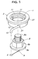
- the fastener in this first embodiment comprises a torsion coil spring 1 and a stopper 2 as illustrated in FIG 1 and FIG. 2.
- torsion coil spring 1 and stopper 2 both made of metal, but they may be made of other single or composite material such as synthetic resin as the occasion demands.
- the torsion coil spring 1 is formed of a round wire member 11 wound in a spiral manner in conformity with the nut Bb of the fastening member B.
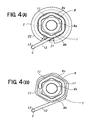
- the torsion coil spring 1 wound spirally is formed in cylindrical cone shape, which is gradually increased axially in diameter toward one end thereof (the side opposite to the fastening member B) in its uncompressed state (see FIG 3(C) and FIG 4(B)), but unchanged radially in diameter in its compressed state (see FIGS. 3(A) and 3(B) and FIG 4(A)).
- a fixing end 13 is formed by bending a straight extension part 12 of the wire member 11 of the spring into an L-shape.
- the stopper 2 is formed as a ring to be fitted to the outer periphery of the torsion coil spring 1 in the radially compressed state.
- an insert groove 21 In one end face portion of the stopper 2 (the side opposite to the fastening member B), there is formed an insert groove 21 through which the extension part 12 of the torsion coil spring 1 passes.
- a flange 22 At the other end face portion of the stopper 2 (the side far from fastening member B), there is formed a flange 22 projecting outward from the end face.
- the torsion coil spring 1 and stopper 2 may possibly be assembled preliminarily by using a machine tool at a factory or manually at the working site, taking elastic fatigue of the torsion coil spring 1 into consideration.
- the torsion coil spring 1 formed in the cylindrical cone shape is assembled by being squeezed into the stopper 2 at the working site and then inserting the extension part 12 of the torsion coil spring 1 in the insert groove 21 in the stopper 2 from the end face side. In this manner, assembling of the fastener can easily be performed without trouble.
- the assembled torsion coil spring 1 and stopper 2 are substantially united in one body by the action of the elasticity of the torsion coil spring 1 so as not to unexpectedly break unification of the torsion coil spring 1 and stopper 2.
- the assembled torsion coil spring 1 and stopper 2 can steadily be kept.
- the torsion coil spring 1 and stopper 2 thus assembled are integrally depressed in the axial direction to be fitted to the nut Bb of the fastening member B.
- the friction caused between the torsion coil spring and the nut should be determined so as not to separate the torsion coil spring 1 away from the stopper 2.
- the fixing end 13 of the torsion coil spring 1 is inserted through a fixing hole C formed in the mounting base A. At this time, it is desirable to insert the fixing end 13 into the fixing hole C while slightly rotating the extension part 12 of the torsion coil spring 1 so as to accumulate the resilience of the spring 1.
- the stopper 2 is pulled up in the axial direction with a finger or tool hooked on the flange 22, as shown in FIG. 2, FIG. 3(C) and FIG. 4(B).
- the resilience of the torsion coil spring 1 is increased to weaken the integrated state of the torsion coil spring 1 and stopper 2 and increase the engagement of the torsion coil spring 1 and the nut Bb of the fastening member B.
- the stopper 2 can be smoothly separated from the torsion coil spring 1, keeping the engagement of the torsion coil spring 1 and the nut Bb of the fastening member B.
- the torsion coil spring 1 is brought back into its original cylindrical cone shape, consequently to make removing of the stopper easy appreciably.
- the torsion coil spring 1 separated from the stopper 1 is released from restriction of tightening torque accumulated by itself, thus to exert the tightening torque to the fastening member B. Consequently, the fastening conditions of the fastening member B can be automatically regulated, preventing slack of the fastening member B.
- the torsion coil spring 1 separated from the stopper 1 slightly expands in the axial and radial directions at that time, the torsion coil spring 1 resiliently expands only to a slight degree.
- the fastener can be made small in size in whole, preventing the tightening torque exerted to the fastening member from weakening due to escape of the torque in the radial direction.
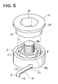
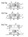
- FIGS. 5 through FIG 7 illustrate the second embodiment of the best mode for carrying out the invention.
- the stopper 2 in this second embodiment is not provided with a flange like the flange 22 seen in the first embodiment and made longer so as to assure a clearance space S for accommodating the wire member 11 of the torsion coil spring 1 by one wire.
- the driving cylinder 3 When detaching the stopper 2, a driving cylinder 3 is used.
- the driving cylinder 3 has a cylindrical outer surface 31 corresponding to the inner surface of the stopper 2 and a hexagonal inner surface 32 corresponding to the configuration of the nut Bb of the fastening member B, and is provided with a flange 33 expanding outward at one end (rear side with respect to a driving direction).
- the torsion coil spring 1 and stopper 2 can be prevented from accidentally dropping off due to skidding or mechanical shock by virtue of the clearance space S of the stopper 2.
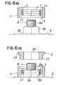
- the torsion ceil spring 1 and stopper 2 are axially depressed in a unified manner to be fitted to the fastening member B, as shown in FIG. 5 and FIGS. 6(A) and 6(B).
- this embodiment is the same as the aforementioned first embodiment, but the torsion coil spring 1 may not steadily be fitted to the nut Bb of the fastening member B. That is, the torsion coil spring 1 may not necessarily be made with a high degree of accuracy, and therefore, it can be produced at a low cost with ease.
- the fixing end 13 of the torsion coil spring 1 is inserted into the fixing hole C in the same manner as the first embodiment
- the driving cylinder 3 is driven into between the stopper 2 and the nut Bb of the fastening member B as shown in FIGS. 7(A) and 7(B).
- the flange 33 of the driving cylinder 3 has a function of restricting the driving limit of the driving cylinder.
- the stopper 2 is pushed up by virtue of reactive force, which is caused by placing the driving cylinder 3 in position between the stopper and the nut to concentrate the elasticity of the spring to the mounting end of the fastening member B.
- the stopper 2 and driving cylinder 3 are automatically released from the torsion coil spring 1 by virtue of the reactive force thus caused (see FIG. 7(C)).
- this second embodiment has another advantage in that the stopper 2 can easily be removed when increasing the tightening torque of the torsion coil spring 1.
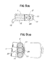
- FIGS. 8(A) and 8(B) illustrate the third embodiment of the best mode for carrying out the invention.
- the stopper 2 in this third embodiment is formed of a string member such as a wire for gathering round the piled wire member 11 of the torsion coil spring 1.
- the torsion coil spring 1 can easily be removed only by cutting the string-like stopper 2.
- FIGS. 9(A) and 9(B) illustrate the fourth embodiment of the best mode for carrying out the invention.
- the stopper 2 in the fourth embodiment is formed of a frame member for gathering round the piled wire member 11 of the torsion coil spring 1.
- the frame-like stopper 2 assumes the shape like an ellipse clip having a discontinuity (cut part) 23 formed in a part of the circumference thereof and is provided with a pull-up type finger hook 24.
- the stopper 2 can easily be taken out only by pulling up the frame-like stopper 2 with a finger hooked in the finger hook 24 to destroy the stopper.
- the fixing end 13 of the torsion coil spring 1 may be formed as a hook piece engageable with a projection or a nail to be driven into the mounting base A.
- the fastener according to the invention can be applied to the fastening member made of metal, concrete or any other material. Further, the fastener of the invention is also applicable to any fastening member, which is fastened by rotation onto the mounting base, other than a bolt or nut as touched on above.
Landscapes
- Engineering & Computer Science (AREA)
- General Engineering & Computer Science (AREA)
- Mechanical Engineering (AREA)
- Springs (AREA)
- Hand Tools For Fitting Together And Separating, Or Other Hand Tools (AREA)
- Clamps And Clips (AREA)
- Bolts, Nuts, And Washers (AREA)
- Separation By Low-Temperature Treatments (AREA)
- Formation And Processing Of Food Products (AREA)
- Specific Sealing Or Ventilating Devices For Doors And Windows (AREA)
- Massaging Devices (AREA)
- Slide Fasteners, Snap Fasteners, And Hook Fasteners (AREA)
- Insertion Pins And Rivets (AREA)
Applications Claiming Priority (1)
| Application Number | Priority Date | Filing Date | Title |
|---|---|---|---|
| PCT/JP2002/012588 WO2003091582A1 (fr) | 2002-12-02 | 2002-12-02 | Systeme de fixation |
Publications (3)
| Publication Number | Publication Date |
|---|---|
| EP1568902A1 EP1568902A1 (en) | 2005-08-31 |
| EP1568902A4 EP1568902A4 (en) | 2005-12-21 |
| EP1568902B1 true EP1568902B1 (en) | 2007-03-14 |
Family
ID=29267278
Family Applications (1)
| Application Number | Title | Priority Date | Filing Date |
|---|---|---|---|
| EP02783736A Expired - Lifetime EP1568902B1 (en) | 2002-12-02 | 2002-12-02 | Fastener |
Country Status (6)
| Country | Link |
|---|---|
| US (1) | US7316533B2 (ja) |
| EP (1) | EP1568902B1 (ja) |
| JP (1) | JP4241398B2 (ja) |
| AT (1) | ATE356939T1 (ja) |
| DE (1) | DE60218910T2 (ja) |
| WO (1) | WO2003091582A1 (ja) |
Families Citing this family (18)
| Publication number | Priority date | Publication date | Assignee | Title |
|---|---|---|---|---|
| WO2003001074A1 (en) * | 2001-06-21 | 2003-01-03 | Black & Decker Inc. | Method and apparatus for fastening steel framing members |
| GB0526084D0 (en) * | 2005-12-21 | 2006-02-01 | Airbus Uk Ltd | An aircraft structure and a fastener for use therewith |
| US20080060296A1 (en) * | 2006-09-12 | 2008-03-13 | Espinosa Thomas M | Building having a hold down system |
| US20080226416A1 (en) * | 2007-03-12 | 2008-09-18 | Benns Michael J | Anti-Rotation Device |
| US8215884B2 (en) * | 2008-12-16 | 2012-07-10 | Lockheed Martin Corporation | Connector for use in high vibration environment |
| US9496700B2 (en) * | 2011-09-29 | 2016-11-15 | Hubbell Incorporated | Side-loading quadrant deadend clamp assembly |
| US9038966B2 (en) * | 2011-09-29 | 2015-05-26 | Hubbell Incorporated | Side-loading quadrant deadend clamp assembly |
| US8881478B2 (en) | 2012-06-22 | 2014-11-11 | Simpson Strong-Tie Company, Inc. | Ratcheting take-up device |
| US8608421B1 (en) * | 2012-12-28 | 2013-12-17 | John T. Halsey | Nut tightening system |
| US9394706B2 (en) | 2013-10-08 | 2016-07-19 | Simpson Strong-Tie Company, Inc. | Concrete anchor |
| CN103522258B (zh) * | 2013-10-22 | 2015-06-17 | 广州穗达电气有限公司 | 涡卷弹簧安装设备 |
| US9163655B2 (en) | 2014-01-14 | 2015-10-20 | Kaoru Taneichi | Thrust nut |
| JP6307397B2 (ja) * | 2014-09-18 | 2018-04-04 | 首都高速道路株式会社 | 固定具 |
| DE202015106449U1 (de) * | 2015-11-26 | 2017-03-01 | Wolfgang-Peter Geller | Sicherungselement für eine Konnektorschraube |
| JP6857536B2 (ja) * | 2017-04-06 | 2021-04-14 | 株式会社やまびこ | 携帯型切断機 |
| DE102020104410A1 (de) | 2020-02-19 | 2021-08-19 | Te Connectivity Germany Gmbh | Kontakteinrichtung, Kontaktsystem und Verfahren zur Montage solch eines Kontaktsystems |
| CN113759484B (zh) * | 2020-06-02 | 2023-08-15 | 成都鼎桥通信技术有限公司 | 轨道弹簧安装治具 |
| CN112303091A (zh) * | 2020-11-03 | 2021-02-02 | 翁婷婷 | 一种防松动便于拆卸机械紧固件 |
Family Cites Families (14)
| Publication number | Priority date | Publication date | Assignee | Title |
|---|---|---|---|---|
| US582424A (en) * | 1897-05-11 | Nut-lock | ||
| US677603A (en) * | 1900-03-30 | 1901-07-02 | Thomas E Shortell | Nut-lock. |
| US868622A (en) * | 1907-03-16 | 1907-10-15 | Continentale Fixator | Locking arrangement for nuts, screws, &c. |
| US1143247A (en) * | 1914-11-11 | 1915-06-15 | Edward T Bates | Nut-lock. |
| US1301958A (en) * | 1916-10-20 | 1919-04-29 | Clarence M Mendenhall | Nut and bolt lock. |
| US3512565A (en) * | 1968-06-28 | 1970-05-19 | United Nuclear Corp | Self-retaining nut structure |
| US3620574A (en) * | 1969-04-23 | 1971-11-16 | Paul D Cox | Lug lock |
| JPS4914857A (ja) | 1972-06-03 | 1974-02-08 | ||
| JPS51127956A (en) | 1975-05-01 | 1976-11-08 | Shigezo Tatsumi | Self expending tightening spring body for tightening bottom part |
| US4812096A (en) * | 1987-12-11 | 1989-03-14 | Peterson Peter O | Self-tightening nut |
| DE4121524C2 (de) * | 1991-06-28 | 1994-07-14 | Deutsche Aerospace Airbus | Schraubenverbindung |
| JPH06323322A (ja) | 1993-05-10 | 1994-11-25 | Kaname Hanaki | 緩み止めナット |
| CN1128691C (zh) * | 1998-07-06 | 2003-11-26 | 谷村和明 | 螺丝自动紧固装置 |
| EP1310685B1 (en) | 2000-08-16 | 2005-10-26 | Kashiraishi Inc. | Tightening device |
-
2002
- 2002-12-02 JP JP2003588090A patent/JP4241398B2/ja not_active Expired - Fee Related
- 2002-12-02 EP EP02783736A patent/EP1568902B1/en not_active Expired - Lifetime
- 2002-12-02 US US10/537,025 patent/US7316533B2/en not_active Expired - Fee Related
- 2002-12-02 AT AT02783736T patent/ATE356939T1/de not_active IP Right Cessation
- 2002-12-02 WO PCT/JP2002/012588 patent/WO2003091582A1/ja active IP Right Grant
- 2002-12-02 DE DE60218910T patent/DE60218910T2/de not_active Expired - Lifetime
Also Published As
| Publication number | Publication date |
|---|---|
| US7316533B2 (en) | 2008-01-08 |
| US20060039773A1 (en) | 2006-02-23 |
| JP4241398B2 (ja) | 2009-03-18 |
| DE60218910D1 (de) | 2007-04-26 |
| EP1568902A1 (en) | 2005-08-31 |
| ATE356939T1 (de) | 2007-04-15 |
| DE60218910T2 (de) | 2007-12-06 |
| WO2003091582A1 (fr) | 2003-11-06 |
| JPWO2003091582A1 (ja) | 2006-02-02 |
| EP1568902A4 (en) | 2005-12-21 |
Similar Documents
| Publication | Publication Date | Title |
|---|---|---|
| EP1568902B1 (en) | Fastener | |
| US6450746B1 (en) | Screw retention device having serrations | |
| US4921203A (en) | Spring element for a shock isolating mount | |
| US7306418B2 (en) | Deforming member and captive fastener retaining method | |
| US6062763A (en) | Retainer for a shock mount | |
| US5551817A (en) | Fastener for attaching in one direction | |
| US4783039A (en) | Shock isolating mount | |
| US20030097912A1 (en) | Adaptor device for a wrench | |
| EP1135619B1 (en) | Swage-type fastening system comprising a pin | |
| EP3875415A1 (en) | Fastening device | |
| US20120237316A1 (en) | Floating fastener | |
| JPH0293112A (ja) | 拘束ねじアッセンブリー | |
| JPWO2005121570A1 (ja) | 脱落防止具および緩み止めナット | |
| US5760338A (en) | Wiring harness clamp | |
| US6095481A (en) | Breakaway shock isolating mount | |
| KR20120037510A (ko) | 방진 체결 조립체 | |
| US2878709A (en) | Mine roof bolts having segmented shell biased outwardly by resilient washer | |
| US4402203A (en) | Fastener installation tool | |
| IE862695L (en) | Fixing a handle on a tool | |
| US6796005B2 (en) | Mounting structure for energy absorber | |
| JP2005090681A (ja) | クリップ | |
| EP1348877B1 (en) | Torque resistant grommet | |
| HU220663B1 (hu) | Berendezés felmosóeszközhöz, felmosóeszköz és eljárás a gyártásához | |
| JP2004011876A (ja) | ブラインドナット | |
| JPH1082411A (ja) | 脱落防止用補助具及びこれを含む脱落防止雄ねじ部材 |
Legal Events
| Date | Code | Title | Description |
|---|---|---|---|
| PUAI | Public reference made under article 153(3) epc to a published international application that has entered the european phase |
Free format text: ORIGINAL CODE: 0009012 |
|
| 17P | Request for examination filed |
Effective date: 20050606 |
|
| AK | Designated contracting states |
Kind code of ref document: A1 Designated state(s): AT BE BG CH CY CZ DE DK EE ES FI FR GB GR IE IT LI LU MC NL PT SE SI SK TR |
|
| A4 | Supplementary search report drawn up and despatched |
Effective date: 20051107 |
|
| GRAP | Despatch of communication of intention to grant a patent |
Free format text: ORIGINAL CODE: EPIDOSNIGR1 |
|
| GRAS | Grant fee paid |
Free format text: ORIGINAL CODE: EPIDOSNIGR3 |
|
| GRAA | (expected) grant |
Free format text: ORIGINAL CODE: 0009210 |
|
| AK | Designated contracting states |
Kind code of ref document: B1 Designated state(s): AT BE BG CH CY CZ DE DK EE ES FI FR GB GR IE IT LI LU MC NL PT SE SI SK TR |
|
| PG25 | Lapsed in a contracting state [announced via postgrant information from national office to epo] |
Ref country code: AT Free format text: LAPSE BECAUSE OF FAILURE TO SUBMIT A TRANSLATION OF THE DESCRIPTION OR TO PAY THE FEE WITHIN THE PRESCRIBED TIME-LIMIT Effective date: 20070314 Ref country code: BE Free format text: LAPSE BECAUSE OF FAILURE TO SUBMIT A TRANSLATION OF THE DESCRIPTION OR TO PAY THE FEE WITHIN THE PRESCRIBED TIME-LIMIT Effective date: 20070314 Ref country code: SI Free format text: LAPSE BECAUSE OF FAILURE TO SUBMIT A TRANSLATION OF THE DESCRIPTION OR TO PAY THE FEE WITHIN THE PRESCRIBED TIME-LIMIT Effective date: 20070314 Ref country code: NL Free format text: LAPSE BECAUSE OF FAILURE TO SUBMIT A TRANSLATION OF THE DESCRIPTION OR TO PAY THE FEE WITHIN THE PRESCRIBED TIME-LIMIT Effective date: 20070314 Ref country code: LI Free format text: LAPSE BECAUSE OF FAILURE TO SUBMIT A TRANSLATION OF THE DESCRIPTION OR TO PAY THE FEE WITHIN THE PRESCRIBED TIME-LIMIT Effective date: 20070314 Ref country code: CH Free format text: LAPSE BECAUSE OF FAILURE TO SUBMIT A TRANSLATION OF THE DESCRIPTION OR TO PAY THE FEE WITHIN THE PRESCRIBED TIME-LIMIT Effective date: 20070314 Ref country code: FI Free format text: LAPSE BECAUSE OF FAILURE TO SUBMIT A TRANSLATION OF THE DESCRIPTION OR TO PAY THE FEE WITHIN THE PRESCRIBED TIME-LIMIT Effective date: 20070314 |
|
| REG | Reference to a national code |
Ref country code: GB Ref legal event code: FG4D |
|
| REG | Reference to a national code |
Ref country code: CH Ref legal event code: EP |
|
| REF | Corresponds to: |
Ref document number: 60218910 Country of ref document: DE Date of ref document: 20070426 Kind code of ref document: P |
|
| REG | Reference to a national code |
Ref country code: IE Ref legal event code: FG4D |
|
| PG25 | Lapsed in a contracting state [announced via postgrant information from national office to epo] |
Ref country code: SE Free format text: LAPSE BECAUSE OF FAILURE TO SUBMIT A TRANSLATION OF THE DESCRIPTION OR TO PAY THE FEE WITHIN THE PRESCRIBED TIME-LIMIT Effective date: 20070614 |
|
| PG25 | Lapsed in a contracting state [announced via postgrant information from national office to epo] |
Ref country code: ES Free format text: LAPSE BECAUSE OF FAILURE TO SUBMIT A TRANSLATION OF THE DESCRIPTION OR TO PAY THE FEE WITHIN THE PRESCRIBED TIME-LIMIT Effective date: 20070625 |
|
| PG25 | Lapsed in a contracting state [announced via postgrant information from national office to epo] |
Ref country code: PT Free format text: LAPSE BECAUSE OF FAILURE TO SUBMIT A TRANSLATION OF THE DESCRIPTION OR TO PAY THE FEE WITHIN THE PRESCRIBED TIME-LIMIT Effective date: 20070814 |
|
| NLV1 | Nl: lapsed or annulled due to failure to fulfill the requirements of art. 29p and 29m of the patents act | ||
| REG | Reference to a national code |
Ref country code: CH Ref legal event code: PL |
|
| EN | Fr: translation not filed | ||
| EN | Fr: translation not filed | ||
| PG25 | Lapsed in a contracting state [announced via postgrant information from national office to epo] |
Ref country code: SK Free format text: LAPSE BECAUSE OF FAILURE TO SUBMIT A TRANSLATION OF THE DESCRIPTION OR TO PAY THE FEE WITHIN THE PRESCRIBED TIME-LIMIT Effective date: 20070314 |
|
| PG25 | Lapsed in a contracting state [announced via postgrant information from national office to epo] |
Ref country code: CZ Free format text: LAPSE BECAUSE OF FAILURE TO SUBMIT A TRANSLATION OF THE DESCRIPTION OR TO PAY THE FEE WITHIN THE PRESCRIBED TIME-LIMIT Effective date: 20070314 |
|
| PLBE | No opposition filed within time limit |
Free format text: ORIGINAL CODE: 0009261 |
|
| STAA | Information on the status of an ep patent application or granted ep patent |
Free format text: STATUS: NO OPPOSITION FILED WITHIN TIME LIMIT |
|
| PG25 | Lapsed in a contracting state [announced via postgrant information from national office to epo] |
Ref country code: DK Free format text: LAPSE BECAUSE OF FAILURE TO SUBMIT A TRANSLATION OF THE DESCRIPTION OR TO PAY THE FEE WITHIN THE PRESCRIBED TIME-LIMIT Effective date: 20070314 |
|
| 26N | No opposition filed |
Effective date: 20071217 |
|
| PG25 | Lapsed in a contracting state [announced via postgrant information from national office to epo] |
Ref country code: IT Free format text: LAPSE BECAUSE OF FAILURE TO SUBMIT A TRANSLATION OF THE DESCRIPTION OR TO PAY THE FEE WITHIN THE PRESCRIBED TIME-LIMIT Effective date: 20070314 Ref country code: GR Free format text: LAPSE BECAUSE OF FAILURE TO SUBMIT A TRANSLATION OF THE DESCRIPTION OR TO PAY THE FEE WITHIN THE PRESCRIBED TIME-LIMIT Effective date: 20070615 Ref country code: FR Free format text: LAPSE BECAUSE OF FAILURE TO SUBMIT A TRANSLATION OF THE DESCRIPTION OR TO PAY THE FEE WITHIN THE PRESCRIBED TIME-LIMIT Effective date: 20071102 |
|
| PG25 | Lapsed in a contracting state [announced via postgrant information from national office to epo] |
Ref country code: MC Free format text: LAPSE BECAUSE OF NON-PAYMENT OF DUE FEES Effective date: 20071231 |
|
| PG25 | Lapsed in a contracting state [announced via postgrant information from national office to epo] |
Ref country code: IE Free format text: LAPSE BECAUSE OF NON-PAYMENT OF DUE FEES Effective date: 20071203 |
|
| PG25 | Lapsed in a contracting state [announced via postgrant information from national office to epo] |
Ref country code: FR Free format text: LAPSE BECAUSE OF FAILURE TO SUBMIT A TRANSLATION OF THE DESCRIPTION OR TO PAY THE FEE WITHIN THE PRESCRIBED TIME-LIMIT Effective date: 20070314 |
|
| PG25 | Lapsed in a contracting state [announced via postgrant information from national office to epo] |
Ref country code: EE Free format text: LAPSE BECAUSE OF FAILURE TO SUBMIT A TRANSLATION OF THE DESCRIPTION OR TO PAY THE FEE WITHIN THE PRESCRIBED TIME-LIMIT Effective date: 20070314 |
|
| PG25 | Lapsed in a contracting state [announced via postgrant information from national office to epo] |
Ref country code: CY Free format text: LAPSE BECAUSE OF FAILURE TO SUBMIT A TRANSLATION OF THE DESCRIPTION OR TO PAY THE FEE WITHIN THE PRESCRIBED TIME-LIMIT Effective date: 20070314 |
|
| PG25 | Lapsed in a contracting state [announced via postgrant information from national office to epo] |
Ref country code: LU Free format text: LAPSE BECAUSE OF NON-PAYMENT OF DUE FEES Effective date: 20071202 Ref country code: BG Free format text: LAPSE BECAUSE OF FAILURE TO SUBMIT A TRANSLATION OF THE DESCRIPTION OR TO PAY THE FEE WITHIN THE PRESCRIBED TIME-LIMIT Effective date: 20070614 |
|
| PG25 | Lapsed in a contracting state [announced via postgrant information from national office to epo] |
Ref country code: TR Free format text: LAPSE BECAUSE OF FAILURE TO SUBMIT A TRANSLATION OF THE DESCRIPTION OR TO PAY THE FEE WITHIN THE PRESCRIBED TIME-LIMIT Effective date: 20070314 |
|
| PGFP | Annual fee paid to national office [announced via postgrant information from national office to epo] |
Ref country code: GB Payment date: 20101207 Year of fee payment: 9 |
|
| PGFP | Annual fee paid to national office [announced via postgrant information from national office to epo] |
Ref country code: DE Payment date: 20111222 Year of fee payment: 10 |
|
| GBPC | Gb: european patent ceased through non-payment of renewal fee |
Effective date: 20121202 |
|
| REG | Reference to a national code |
Ref country code: DE Ref legal event code: R119 Ref document number: 60218910 Country of ref document: DE Effective date: 20130702 |
|
| PG25 | Lapsed in a contracting state [announced via postgrant information from national office to epo] |
Ref country code: DE Free format text: LAPSE BECAUSE OF NON-PAYMENT OF DUE FEES Effective date: 20130702 |
|
| PG25 | Lapsed in a contracting state [announced via postgrant information from national office to epo] |
Ref country code: GB Free format text: LAPSE BECAUSE OF NON-PAYMENT OF DUE FEES Effective date: 20121202 |