EP1568601B1 - Unterseeboot mit einem zwischen die Batterie und die Brennstoffzellenanlage geschaltet DC/DC Steller - Google Patents
Unterseeboot mit einem zwischen die Batterie und die Brennstoffzellenanlage geschaltet DC/DC Steller Download PDFInfo
- Publication number
- EP1568601B1 EP1568601B1 EP05001069A EP05001069A EP1568601B1 EP 1568601 B1 EP1568601 B1 EP 1568601B1 EP 05001069 A EP05001069 A EP 05001069A EP 05001069 A EP05001069 A EP 05001069A EP 1568601 B1 EP1568601 B1 EP 1568601B1
- Authority
- EP
- European Patent Office
- Prior art keywords
- fuel cell
- battery
- controller
- current
- voltage
- Prior art date
- Legal status (The legal status is an assumption and is not a legal conclusion. Google has not performed a legal analysis and makes no representation as to the accuracy of the status listed.)
- Expired - Lifetime
Links
- 239000000446 fuel Substances 0.000 title claims abstract description 85
- 238000000034 method Methods 0.000 claims description 11
- 238000009434 installation Methods 0.000 claims 10
- 230000002123 temporal effect Effects 0.000 claims 1
- 239000012080 ambient air Substances 0.000 abstract 1
- 239000003990 capacitor Substances 0.000 description 4
- 238000010586 diagram Methods 0.000 description 3
- 241000196324 Embryophyta Species 0.000 description 2
- 230000000903 blocking effect Effects 0.000 description 2
- 230000006378 damage Effects 0.000 description 2
- 230000001419 dependent effect Effects 0.000 description 2
- 230000001105 regulatory effect Effects 0.000 description 2
- 239000004065 semiconductor Substances 0.000 description 2
- UFHFLCQGNIYNRP-UHFFFAOYSA-N Hydrogen Chemical compound [H][H] UFHFLCQGNIYNRP-UHFFFAOYSA-N 0.000 description 1
- 230000032683 aging Effects 0.000 description 1
- QVGXLLKOCUKJST-UHFFFAOYSA-N atomic oxygen Chemical compound [O] QVGXLLKOCUKJST-UHFFFAOYSA-N 0.000 description 1
- 238000010276 construction Methods 0.000 description 1
- 230000007547 defect Effects 0.000 description 1
- 230000006735 deficit Effects 0.000 description 1
- 230000018109 developmental process Effects 0.000 description 1
- 230000000694 effects Effects 0.000 description 1
- 230000005611 electricity Effects 0.000 description 1
- 230000002349 favourable effect Effects 0.000 description 1
- 239000007789 gas Substances 0.000 description 1
- 238000009499 grossing Methods 0.000 description 1
- 239000001257 hydrogen Substances 0.000 description 1
- 229910052739 hydrogen Inorganic materials 0.000 description 1
- 239000007800 oxidant agent Substances 0.000 description 1
- 230000001590 oxidative effect Effects 0.000 description 1
- 239000001301 oxygen Substances 0.000 description 1
- 229910052760 oxygen Inorganic materials 0.000 description 1
- 239000000376 reactant Substances 0.000 description 1
- 230000000630 rising effect Effects 0.000 description 1
- 239000000126 substance Substances 0.000 description 1
- 230000007704 transition Effects 0.000 description 1
Images

Classifications
-
- B—PERFORMING OPERATIONS; TRANSPORTING
- B63—SHIPS OR OTHER WATERBORNE VESSELS; RELATED EQUIPMENT
- B63G—OFFENSIVE OR DEFENSIVE ARRANGEMENTS ON VESSELS; MINE-LAYING; MINE-SWEEPING; SUBMARINES; AIRCRAFT CARRIERS
- B63G8/00—Underwater vessels, e.g. submarines; Equipment specially adapted therefor
- B63G8/08—Propulsion
-
- B—PERFORMING OPERATIONS; TRANSPORTING
- B63—SHIPS OR OTHER WATERBORNE VESSELS; RELATED EQUIPMENT
- B63H—MARINE PROPULSION OR STEERING
- B63H21/00—Use of propulsion power plant or units on vessels
- B63H2021/003—Use of propulsion power plant or units on vessels the power plant using fuel cells for energy supply or accumulation, e.g. for buffering photovoltaic energy
-
- Y—GENERAL TAGGING OF NEW TECHNOLOGICAL DEVELOPMENTS; GENERAL TAGGING OF CROSS-SECTIONAL TECHNOLOGIES SPANNING OVER SEVERAL SECTIONS OF THE IPC; TECHNICAL SUBJECTS COVERED BY FORMER USPC CROSS-REFERENCE ART COLLECTIONS [XRACs] AND DIGESTS
- Y02—TECHNOLOGIES OR APPLICATIONS FOR MITIGATION OR ADAPTATION AGAINST CLIMATE CHANGE
- Y02T—CLIMATE CHANGE MITIGATION TECHNOLOGIES RELATED TO TRANSPORTATION
- Y02T90/00—Enabling technologies or technologies with a potential or indirect contribution to GHG emissions mitigation
- Y02T90/40—Application of hydrogen technology to transportation, e.g. using fuel cells
Definitions
- the invention relates to a submarine according to the features specified in the preamble of claim 1 and a method for operating an electrical supply network of such a submarine.
- a submarine and method is of the publication Journal of power sources; Elsevier Sequoia S.A. Lausanne, CH; "Fuel cells going on-board”; Sattler G .; Bol. 86, No. 1-2, March 2000 (2000-03), pages 61-67; ISSN: 0378-7753 known
- Air Independent Propulsion AIP
- the rechargeable batteries As well as a fuel cell system to maximize the range of the boat in a deep dive, i. in a depth, in which even with the help of the snorkel no connection to the outside air is possible, to enlarge. It is not only the electric motor driven propeller, but also the electrical system to supply.
- the fuel cell system hydrogen is catalytically oxidized with the release of electrical energy.
- the oxidant used on board stored oxygen.
- battery and fuel cell system are connected in parallel, it is systemically appropriate to cover the basic needs of electrical energy from the fuel cell system and to supply additional energy only from the battery for peak power.
- the fuel cell system is to protect against sudden load and voltage jumps, so that even with sudden load changes in the system, the battery must cover the sudden energy deficit in the transition until the fuel cell system has risen to the increased power or has reached full load.
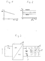
- the fuel cell system supplies a DC voltage whose magnitude depends on the current load current and other parameters, such as the current load current. Gas pressure, aging, temperature, etc. is dependent. The terminal voltage changes depending on the current in the ratio of about 1: 2.
- a typical characteristic of such a fuel cell system is shown in FIG.
- the voltage of the traction battery is dependent on the current state of charge and in the range up to the rated fuel cell current almost independent of power.
- the voltage of the driving battery changes almost in the ratio 1: 1.5 between empty battery at full load and full battery without load current.
- the battery voltage can rise to 1.4 times the operating voltage.
- the corresponding voltage / load characteristics of such a battery are shown in FIG.
- the battery Since the battery has a voltage characteristic which depends on a plurality of operating parameters and which differs from that of the fuel cell system, precaution must be taken against undesired equalizing currents. In particular, return currents from the battery to be avoided in the fuel cell system. An uncontrolled charging the battery from the fuel cell system is not desirable. Return currents from the battery into the fuel cell system are avoided in the prior art in that the fuel cell system is designed so that its output voltage is above the battery voltage. In order to avoid that due to this increased voltage level of the fuel cell system against the battery an unwanted charging current flows into the battery, this is via diodes connected, but which must be bridged in battery charging by switching devices.
- the diodes must be dimensioned so that they can carry the maximum current, ie the power required at the highest power output of the propeller motor and the supply network.
- the diodes must be bridged above a certain current with switching devices, this is technically complex and expensive.
- the invention has the object, a generic submarine with an outside air independent drive and power supply in such a way that the aforementioned disadvantages are avoided or at least reduced. It is intended below a corresponding method for operating an electrical Supply network of a submarine with fuel cell system and battery are created, which avoids the aforementioned problems.
- Claim 8 defines an inventive method for operating an electrical supply network of a submarine.
- Advantageous embodiments of the invention are specified in the subclaims, the following description and the drawing.
- the basic idea of the present invention is not to switch the fuel cell system directly parallel to the battery but to integrate it via a DC / DC controller.
- This solution according to the invention has the advantage that, on the one hand, the output voltage of the fuel cell system is arbitrarily adjustable within limits over the DC / DC controller and, on the other hand, reliable return currents from the battery or the supply network to the fuel cell system are avoided.
- the fuel cell system is galvanically isolated by the DC / DC controller for decoupling from the battery, the supply network and thus the electrical loads, so that sudden load changes must have no immediate effect on the fuel cell system.
- the DC / DC controller is a power electronic system that is capable of generating a DC output voltage which, in the specified range, can be substantially higher or lower than the DC voltage of the fuel cell system at the input of the actuator, depending on the system requirement.
- This DC / DC controller is assigned to the system in such a way that the power demanded from the system is adapted in accordance with the different voltage levels and provided primarily by the fuel cell system can. Due to the better efficiency of the fuel cell system at partial load and the chemical efficiency of the battery charge / discharge can be ensured with the help of the DC / DC controller via an appropriate regulation of the voltage that the base load is always covered by the fuel cell system, while the power peaks or sudden load jumps are covered by the battery. It is thus possible optimal use of reactants.
- the fuel cell system can be run at rated power, which then excess power can be used to charge the battery.
- the DC / DC controller is preferably associated with a current controller in a lowest control level, which ensures that in the DC / DC controller flowing current does not exceed a predetermined maximum value. Since a fuel cell system typically consists of a plurality of fuel cells connected in series to stacks and in turn connected in parallel stacks, for this current control of the lowest control level each individual channel, so each stack assign such a current regulator, so that the total current does not exceed a predetermined value. This control of the lowest control level thus effectively protects the fuel cell system from overloading.
- the DC / DC controller has a further current controller in a lower control level, which ensures that the output current of the DC / DC controller does not exceed a predetermined, preferably the maximum permissible value.
- the current controller for the output current of the DC / DC controller is advantageously superimposed on a voltage regulator, which ensures that the output voltage at the DC / DC controller does not exceed a predetermined, preferably the maximum value.
- This maximum permissible value is typically defined by the blocking capability of the output rectifier.
- a voltage regulator is primarily provided which regulates the output voltage of the DC / DC controller, for preferably 2 modes, namely normal operation and charging mode.
- the output voltage of the DC / DC controller is raised until a corresponding charging current of the battery is established.
- the control according to the invention is designed so that the fuel cell system is operated in the nominal load range.
- the voltage at the output of the DC / DC controller is controlled so that the battery current is zero or at least tends to zero.
- This regulation has the advantage that the base load of the electrical supply of the submarine in AIP operation is provided by the fuel cell system, ie a partial load range in which it is particularly favorable in terms of energy, i. works with high efficiency.
- the regulation is thus carried out so that in a sudden increase in load by an electrical load that is still covered by the fuel cell system, first the voltage at the output of the DC / DC adjuster is set so that, starting from the previous load, the voltage to a predetermined time course, which preferably corresponds to the load rise profile of the fuel cell system is raised again.
- the increase in load exceeds the power of the fuel cell system for a short or longer period of time, it is provided according to the invention to set the output voltage at the DC / DC adjuster so that the maximum permissible current for the fuel cell system is not exceeded, such that when it increases Electricity requirement of the additional partial flow is covered by the battery.
- the DC / DC controller is set or regulated to a predetermined voltage, preferably the rated voltage of the supply network.
- the DC / DC controller can then supply the on-board network as part of the capacity of the BZA alone. This regulation is intended as a so-called accidental circuit, if, for whatever reason, the battery should fail.
- the output voltage of the DC / DC controller is raised so far that at least a partial current flows into the battery.
- the voltage control is expediently carried out so that the fuel cell system is operated in the nominal load range.
- FIG. 3 The simplified illustration of the power supply for a submarine shown with reference to FIG. 3 shows a fuel cell system 1 whose electrical output is connected to the input of a DC / DC regulator 2.
- the output of the DC / DC controller 2 is parallel to a rechargeable battery 3 and forms the electrical supply network of the submarine, which consists on the one hand to power the propeller driving a motor 4 and other consumers 5 of the electrical system.
- the fuel cell system 1 is shown only symbolically and consists in a conventional manner of several fuel cell modules, in the form of stacks, which are connected in parallel, possibly in series. Each individual module / stack consists of a large number of series-connected Fuel cells. The output voltage of each fuel cell and thus also corresponding to the number of series-connected fuel cells resulting output voltage of a fuel cell module is typical.
- the battery 3 is, as usual in submarines, from a plurality of blocks connected in series to battery cells, wherein a plurality of blocks in turn may be connected in parallel.
- the construction of the DC / DC controller 2 can be seen with reference to FIGS. 4 and 5.
- the input 6 of the DC / DC controller which is electrically connected to the output of the fuel cell system, has an input capacitor C b whose capacitance is parallel to the input 6.
- an IGBT (insuleted gate bipolar transistor) converter 7 is connected, which converts the DC voltage applied to the input 6 into a high-frequency AC voltage. This is done with the help of 4 power transistors T 1 to T 4 , which in each case a freewheeling diode D 1 to D 4 is connected in anti-parallel.
- This switched by the power semiconductors T 1 to T 4 from the voltage applied to the input DC voltage is applied to the primary coil of a transformer 8, which transforms to a voltage of the appropriate height.
- This voltage applied to the secondary side of the transformer 8 AC voltage is rectified by means of a bridge rectifier 9, which is followed by an LC element consisting of current smoothing reactor 10 and capacitor C a .
- the transmitted power or the output voltage at the output 11 can be set within wide limits.
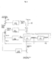
- the control is carried out as shown with reference to FIG. 6.
- the DC / DC controller 2 with the parallel-connected network (consumer 5, motor 4, Battery 3) forms the actual controlled system whose output voltage is regulated.
- a current controller 13 is provided, which controls the DC / DC controller 2, and limits the output current of the DC / DC controller 2 to a maximum value.
- the current controller 13 is superimposed on a voltage regulator 14, which ensures compliance with the maximum output voltage of the DC / DC controller 2 and thus the electrical supply of the submarine.
- This voltage regulator 14 ensures that the output voltage at the DC / DC controller 2 does not rise above the voltage permissible for the rectifier 9 in the output 11 of the DC / DC regulator 2 and thus prevents the blocking capability of the rectifier 9 from being exceeded.
- This voltage regulator 14 also allows the operation of the network with a constant voltage without a battery connected in parallel, the so-called accidental circuit 15, in which a constant voltage is predetermined and which is provided for the operation of the system in case of failure or defect of the battery 3.
- the so-called accidental circuit 15 in which a constant voltage is predetermined and which is provided for the operation of the system in case of failure or defect of the battery 3.
- the switching position shown in FIG. 6 there is only one voltage regulator for a plurality of channels connected in parallel (consisting of BZ-Strack and DC / DC controller) which transmits the same current setpoint to all channels so that a perfect parallel operation is guaranteed.
- the setpoint of the voltage regulator is limited to a maximum value.
- a battery power regulator 16 is provided, which is provided exclusively for battery charging mode.
- This controller is designed to maximize fuel cell performance to cover current power requirements. This is always the case when the battery current is zero or tends towards zero. For this, the battery current is measured and fed at 17 the battery power regulator. With the battery power regulator 16, it is thus possible to always regulate the output power of the DC / DC regulator 2, that the battery current is minimized.
- the power requirement of the system is always provided by the fuel cell system 1, at least as long as there are no sudden loads or the fuel cell system 1 has not yet reached its maximum power.
- a further current regulator 18 is provided, which compares the input current actual value of the DC / DC controller 2 with the maximum permissible current from the fuel cell system 1 and optionally regulates the fuel cell system back.
- this current regulator 18 ensures that in case of sudden power requirement, even if this would basically be covered by the fuel cell system 1, to avoid a, albeit short-term overloading of the fuel cell system 1 this is ramped up in a ramp function and the intermediate power requirement covered by the battery 3 becomes.
Landscapes
- Engineering & Computer Science (AREA)
- Mechanical Engineering (AREA)
- Aviation & Aerospace Engineering (AREA)
- Fuel Cell (AREA)
- Charge And Discharge Circuits For Batteries Or The Like (AREA)
- Direct Current Feeding And Distribution (AREA)
Description
- Die Erfindung betrifft ein Unterseeboot gemäß den im Oberbegriff des Anspruchs 1 angegebenen Merkmalen sowie ein Verfahren zum Betreiben eines elektrischen Versorgungsnetzes eines solchen Unterseebootes. Ein solches Unterseeboot sowie Verfahren ist von der Druckschrift Journal of power sources; Elsevier Sequoia S.A. Lausanne, CH; "Fuel celles going on-board"; Sattler G.; Bol. 86, Nr. 1-2, Mârz 2000 (2000-03), Seiten 61-67; ISSN: 0378-7753 bekannt
- Bei nicht nuklear angetriebenen Unterseebooten zählt es heute zum Stand der Technik für den Unterwasserbetrieb als außenluftunabhängige Energiequelle (AIP - Air Independent Propulsion) neben den wiederaufladbaren Batterien auch eine Brennstoffzellenanlage einzusetzen, um die Reichweite des Bootes in tiefgetauchter Fahrt, d.h. in einer Tauchtiefe, in der auch mit Hilfe des Schnorchels keine Verbindung zur Außenluft mehr möglich ist, zu vergrößern. Dabei ist nicht nur der elektromotorisch angetriebene Propeller, sondern auch das Bordnetz zu versorgen.
- In der Brennstoffzellenanlage wird Wasserstoff unter Freisetzung elektrischer Energie katalytisch oxidiert. Als Oxidant wird an Bord gelagerter Sauerstoff verwendet. Aus Betriebsgründen sind Batterie- und Brennstoffzellenanlage parallel geschaltet, dabei ist es systembedingt zweckmäßig, den Grundbedarf elektrischer Energie aus der Brennstoffzellenanlage zu decken und nur für Leistungsspitzen Energie aus der Batterie zusätzlich zuzuführen. Andererseits ist die Brennstoffzellenanlage vor plötzlichen Last- und Spannungssprüngen zu schützen, so dass auch bei sprunghaften Laständerungen im System die Batterie das plötzliche Energiedefizit im Übergang abdecken muss, bis die Brennstoffzellenanlage auf die erhöhte Leistung hochgefahren ist oder aber die Volllast erreicht hat.
- Dies stellt beim Stand der Technik, bei dem Brennstoffzellenanlage und Batterie parallel geschaltet sind, ein Problem dar. Die Brennstoffzellenanlage liefert eine Gleichspannung, deren Höhe vom aktuellen Laststrom und weiteren Parametern, wie z.B. Gasdruck, Alterung, Temperatur usw. abhängig ist. Die Klemmenspannung ändert sich abhängig vom Strom im Verhältnis von etwa 1:2. Eine typische Kennlinie einer solchen Brennstoffzellenanlage ist in Fig. 1 dargestellt.
- Die Spannung der Fahrbatterie hingegen ist vom aktuellen Ladezustand abhängig und im Bereich bis zum Brennstoffzellennennstrom nahezu stromunabhängig. Auch die Spannung der Fahrbatterie ändert sich nahezu im Verhältnis 1:1,5 zwischen leerer Batterie bei Volllast und voller Batterie ohne Laststrom. Während des Ladens hingegen kann die Batteriespannung bis auf das 1,4-fache der Betriebsspannung ansteigen. Die entsprechenden Spannungs-/Lastkennlinien einer solchen Batterie sind in Fig. 2 dargestellt.
- Da die Batterie eine von mehreren Betriebsparametern abhängige Spannungscharakteristik aufweist, die sich von der der Brennstoffzellenanlage unterscheidet, ist Vorsorge gegen unerwünschte Ausgleichsströme zu treffen. Dabei sind insbesondere Rückströme aus der Batterie in die Brennstoffzellenanlage zu vermeiden. Auch ein unkontrolliertes Laden der Batterie aus der Brennstoffzellenanlage ist nicht erwünscht. Rückströme aus der Batterie in die Brennstoffzellenanlage werden beim Stand der Technik dadurch vermieden, dass die Brennstoffzellenanlage so ausgelegt wird, dass ihre Ausgangsspannung oberhalb der Batteriespannung liegt. Um zu vermeiden, dass aufgrund dieses erhöhten Spannungsniveaus der Brennstoffzellenanlage gegenüber der Batterie ein unerwünschter Ladestrom in die Batterie fliest, ist diese über Dioden angeschlossen, die jedoch im Batterieladebetrieb durch Schaltgeräte überbrückt werden müssen. Darüber hinaus müssen die Dioden so dimensioniert sein, dass sie den maximalen Strom, also den Strom, der bei höchster Leistungsabgabe des Propellermotors und des Versorgungsnetzes erforderlich ist, tragen können. Alternativ müssen die Dioden oberhalb einer bestimmten Stromstärke mit Schaltgeräten überbrückt werden, dies ist technisch aufwendig und teuer.
- Eine auslegungsgemäße Anpassung der Brennstoffzellenanlagenspannung ist darüber hinaus nur bedingt möglich, da jede Brennstoffzelle eine typgebundene Spannungshöhe aufweist, welche die Spannungsstufen bei der Auslegung bestimmt. Aufgrund dieser nicht optimierbaren Spannungsauslegung ist meist ein gezielter Ladebetrieb der Batterie mittels der Brennstoffzellenanlage nicht möglich. D.h. der Ladebetrieb erfolgt dann zu einem für die Brennstoffzellenanlage ungünstigen Betrieb, was Wirkungsgradverluste mit sich bringen kann. Durch die galvanische Verbindung der Brennstoffzellenanlage mit der Batterie ist es unvermeidbar, dass alle Last- und Spannungssprünge auch von der Brennstoffzellenanlage direkt zu kompensieren sind. Ein weiterer Nachteil dieser bekannten Schaltungsanordnung liegt darin, dass eine Rückspeisung von Bremsenergie, wie sie im Schubbetrieb durch den mitlaufenden Propeller generiert wird, aufgrund des Spannungsniveaus zwischen Brennstoffzellenanlage und Batterie nicht in die Batterie einspeisbar ist. Eine Einspeisung in die Brennstoffzellenanlage ist hingegen zu vermeiden, weshalb die anfallende Bremsenergie nutzlos und aufwändig in zusätzlichen Widerstandschaltungen abgebaut werden muss.
- Vor diesem Hintergrund liegt der Erfindung die Aufgabe zugrunde, ein gattungsgemäßes Unterseeboot mit einer außenluftunabhängigen Antriebs- und Energieversorgung so auszubilden, dass die vorgenannten Nachteile vermieden oder zumindest vermindert werden. Es soll im Weiteren ein entsprechendes Verfahren zum Betreiben eines elektrischen Versorgungsnetzes eines Unterseebootes mit Brennstoffzellenanlage und Batterie geschaffen werden, das die vorgenannten Probleme vermeidet.
- Der vorrichtungsmäßige Teil der obigen Aufgabe wird durch die in Anspruch 1 angegebenen Merkmale gelöst. Anspruch 8 definiert ein erfindungsgemäßes Verfahren zum Betreiben eines elektrischen Versorgungsnetzes eines Unterseebootes. Vorteilhafte Ausgestaltungen der Erfindung sind in den Unteransprüchen, der nachfolgenden Beschreibung und der Zeichnung angegeben.
- Grundgedanke der vorliegenden Erfindung ist es, die Brennstoffzellenanlage nicht direkt parallel zur Batterie zu schalten, sondern über einen DC/DC-Steller einzubinden. Diese erfindungsgemäße Lösung hat den Vorteil, dass einerseits die Ausgangsspannung der Brennstoffzellenanlage über den DC/DC-Steller in Grenzen beliebig einstellbar ist und andererseits zuverlässig Rückströme von der Batterie oder dem Versorgungsnetz in die Brennstoffzellenanlage vermieden werden. Darüber hinaus ist die Brennstoffzellenanlage durch den DC/DC-Steller zur Entkopplung von der Batterie, vom Versorgungsnetz und somit den elektrischen Verbrauchern galvanisch getrennt, so dass sprunghafte Laständerungen keine unmittelbare Rückwirkung auf die Brennstoffzellenanlage haben müssen.
- Bei dem DC/DC-Steller handelt es sich um eine leistungselektronische Anlage, die in der Lage ist, eine Ausgangsgleichspannung zu erzeugen, die im spezifizierten Rahmen je nach Systemanforderung wesentlich höher oder niedriger sein kann als die Gleichspannung der Brennstoffzellenanlage am Eingang des Stellers. Dieser DC/DC-Steller wird dem System so zugeordnet, dass die aus dem System geforderte Leistung entsprechend den unterschiedlichen Spannungslagen adaptiert und in erster Linie von der Brennstoffzellenanlage zur Verfügung gestellt werden kann. Aufgrund des besseren Wirkungsgrades der Brennstoffzellenanlage bei Teillast sowie des chemischen Wirkungsgrades der Batterie bei Ladung/Entladung kann mit Hilfe des DC/DC-Stellers über eine entsprechende Regelung der Spannung sichergestellt werden, dass die Grundlast stets durch die Brennstoffzellenanlage abgedeckt wird, während die Leistungsspitzen oder plötzliche Lastsprünge durch die Batterie abgedeckt werden. Es ist somit eine optimale Reaktantennutzung möglich.
- Weiterhin kann dann, wenn der Leistungsbedarf des Unterseeboots unter die Nennleistung der Brennstoffzellenanlage fällt, die Brennstoffzellenanlage mit Nennleistung gefahren werden, wobei die dann überschüssige Leistung zum Laden der Batterie genutzt werden kann.
- Um den DC/DC-Steller vor einer Überlast und somit der Zerstörung oder Schädigung der Leistungshalbleiter zu schützen, ist dem DC/DC-Steller vorzugsweise in einer untersten Regelungsebene ein Stromregler zugeordnet, welcher dafür sorgt, dass der in dem DC/DC-Steller fließende Strom einen vorbestimmten, höchst zulässigen Wert nicht überschreitet. Da eine Brennstoffzellenanlage typischerweise aus einer Vielzahl von zu Stacks hintereinander geschalteten Brennstoffzellen und wiederum parallel geschalteten Stacks besteht, ist für diese Stromregelung der untersten Regelungsebene jedem Einzelkanal, also jedem Stack ein solcher Stromregler zuzuordnen, so dass der Gesamtstrom einen vorbestimmten Wert nicht überschreitet. Diese Regelung der untersten Regelungsebene schützt somit die Brennstoffzellenanlage wirksam vor Überlastung.
- Vorteilhaft weist der DC/DC-Steller einen weiteren Stromregler in einer unteren Regelungsebene auf, welche sicherstellt, dass der Ausgangsstrom des DC/DC-Stellers einen vorbestimmten, vorzugsweise den höchstzulässigen Wert nicht überschreitet.
- Dem Stromregler für den Ausgangsstrom des DC/DC-Stellers ist vorteilhaft ein Spannungsregler überlagert, welcher sicherstellt, dass die Ausgangsspannung am DC/DC-Steller einen vorbestimmten, vorzugsweise den höchstzulässigen Wert nicht überschreitet. Dieser höchstzulässige Wert ist typischerweise durch die Sperrfähigkeit des Ausgangsgleichrichters definiert.
- Die vorbeschriebenen Strom- und Spannungsregelungen dienen im Wesentlichen dem sicheren Betrieb des DC/DC-Stellers. Für den optimierten Betrieb der Energieversorgung des Unterseebootes im AIP-Betrieb hingegen ist primär ein Spannungsregler vorgesehen, welcher die Ausgangsspannung des DC/DC-Stellers regelt, und zwar für vorzugsweise 2 Betriebsarten, nämlich zu einen den Normalbetrieb und zum anderen den Ladebetrieb.
- Im Ladebetrieb wird die Ausgangsspannung des DC/DC-Stellers soweit angehoben, bis sich ein entsprechender Ladestrom der Batterie einstellt. Dabei ist die Regelung gemäß der Erfindung so ausgelegt, dass die Brennstoffzellenanlage im Nennlastbereich betrieben wird.
- Im Normalbetrieb hingegen wird die Spannung am Ausgang des DC/DC-Stellers so geregelt, dass der Batteriestrom Null wird oder zumindest gegen Null strebt. Diese Regelung hat den Vorteil, dass die Grundlast der elektrischen Versorgung des Unterseebootes im AIP-Betrieb von der Brennstoffzellenanlage zur Verfügung gestellt wird, also einen Teillastbereich, in dem sie energetisch besonders günstig, d.h. mit hohem Wirkungsgrad arbeitet.
- Die Lastspitzen hingegen werden durch die Batterie abgedeckt, wobei die Regelung so ausgelegt ist, dass bei einem plötzlichen Lastanstieg, dessen elektrische Last durch die Brennstoffzellenanlage abgedeckt werden könnte, dieser Lastanstieg nicht unmittelbar durch die Brennstoffzellenanlage abgedeckt wird, sondern zunächst durch die Batterie und dann langsam ansteigend durch die Brennstoffzellenanlage. Diese Verfahrensweise kommt dem Regelverhalten der Brennstoffzellenanlage entgegen. Die Regelung erfolgt also so, dass bei einem plötzlichen Lastanstieg durch eine elektrische Last, die von der Brennstoffzellenanlage noch abzudecken ist, zunächst die Spannung am Ausgang des DC/DC-Stellers so eingestellt wird, dass ausgehend von der bisherigen Last, die Spannung nach einem vorgegebenen zeitlichen Verlauf, der vorzugsweise dem Lastanstiegsprofil der Brennstoffzellenanlage entspricht, wieder angehoben wird.
- Übersteigt hingegen der Lastanstieg die Leistung der Brennstoffzellenanlage kurzzeitig oder auch längerfristig, so ist gemäß der Erfindung vorgesehen, die Ausgangsspannung am DC/DC-Steller so ein zustellen, dass der für die Brennstoffzellenanlage maximal zulässige Strom nicht überschritten wird, derart, dass bei dann steigendem Strombedarf der zusätzliche Teilstrom von der Batterie abgedeckt wird.
- In Weiterbildung des erfindungsgemäßen Verfahrens ist vorgesehen, dass der DC/DC-Steller auf eine vorbestimmte Spannung, vorzugsweise die Nennspannung des Versorgungsnetzes eingestellt bzw. geregelt wird. Der DC/DC-Steller kann dann im Rahmen des Leistungsvermögens der BZA das Bordnetz alleine versorgen. Diese Regelung ist als so genannte Havarieschaltung vorgesehen, wenn, aus welchen Gründen auch immer, die Batterie ausfallen sollte.
- Zum Laden der Batterie wird die Ausgangsspannung des DC/DC-Stellers soweit angehoben, dass zumindest ein Teilstrom in die Batterie fließt. Dabei erfolgt die Spannungsregelung zweckmäßigerweise so, dass die Brennstoffzellenanlage im Nennlastbereich betrieben wird.
- Die Erfindung ist nachfolgend anhand eines in der Zeichnung dargestellten Ausführungsbeispiels näher erläutert. Es zeigen
- Fig. 1
- ein typische Lastprofil einer Brennstoffzellenanlage,
- Fig. 2
- typische Lastprofile einer Batterie in unterschiedlichen Ladezuständen,
- Fig. 3
- in stark vereinfachter Darstellung ein Schaltbild der Energieversorgungsanlage eines Unterseeboots,
- Fig. 4
- ein Blockschaltbild, welches den funktionalen Aufbau des DC/DC-Stellers darstellt,
- Fig. 5
- ein Schaltbild des DC/DC-Stellers und
- Fig. 6
- einen Signalflussplan der im Zusammenhang mit dem DC/DC-Steller vorgesehenen Regelungen.
- Das anhand von Fig. 3 vereinfacht dargestellte Schaltbild der Energieversorgung für ein Unterseeboot zeigt eine Brennstoffzellenanlage 1, deren elektrischer Ausgang mit dem Eingang eines DC/DC-Stellers 2 verbunden ist. Der Ausgang des DC/DC-Stellers 2 liegt parallel zu einer wiederaufladbaren Batterie 3 und bildet das elektrische Versorgungsnetz des Unterseebootes, das zum einen zur Speisung des einen Propeller antreibenden Motors 4 sowie weiterer Verbraucher 5 des Bordnetzes besteht.
- Die Brennstoffzellenanlage 1 ist dabei nur symbolisch dargestellt und besteht in an sich bekannter Weise aus mehreren Brennstoffzellenmodulen, in Form von Stacks, die parallel, ggf. in Reihe geschaltet sind. Jedes einzelne Modul/Stack besteht aus einer Vielzahl von in Reihe geschalteten Brennstoffzellen. Die Ausgangsspannung einer jeden Brennstoffzelle und somit auch die sich entsprechend der Anzahl der in Reihe geschalteten Brennstoffzellen ergebende Ausgangsspannung eines Brennstoffzellenmoduls ist typbedingt.
- Auch die Batterie 3 besteht, wie in Unterseebooten üblich, aus einer Vielzahl von zu Blöcken in Reihe geschalteten Batteriezellen, wobei mehrere Blöcke wiederum parallel geschaltet sein können.
- Der Aufbau des DC/DC-Stellers 2 ist anhand der Figuren 4 und 5 ersichtlich. Der Eingang 6 des DC/DC-Stellers, der mit dem Ausgang der Brennstoffzellenanlage elektrisch verbunden ist, weist einen Eingangskondensator Cb auf, dessen Kapazität parallel zum Eingang 6 liegt. Parallel dazu ist ein IGBT (Insuleted Gate Bipolare Transistor) Konverter 7 geschaltet, welcher die am Eingang 6 anliegende Gleichspannung in eine hochfrequente Wechselspannung umwandelt. Dies geschieht mit Hilfe von 4 Leistungstransistoren T1 bis T4, denen jeweils eine Freilaufdiode D1 bis D4 antiparallel geschaltet ist. Diese durch die Leistungshalbleiter T1 bis T4 aus der am Eingang anliegenden Gleichspannung geschaltete Wechselspannung wird an die Primärspule eines Transformators 8 gelegt, welcher auf eine Spannung passender Höhe transformiert. Diese an der Sekundärseite des Transformators 8 anliegende Wechselspannung wird mittels eines Brückengleichrichters 9 gleichgerichtet, dem ein LC-Glied, bestehend aus Stromglättungsdrossel 10 und Kondensator Ca nachgeschaltet ist.
- Durch Modulation des Stromes im Wechselstromzwischenkreis 7 kann die übertragene Leistung bzw. die Ausgangsspannung am Ausgang 11 in weiten Grenzen eingestellt werden.
- Die Regelung erfolgt, wie anhand von Fig. 6 dargestellt. Der DC/DC-Steller 2 mit dem parallel geschalteten Netz (Verbraucher 5, Motor 4, Batterie 3) bildet die eigentliche Regelstrecke, deren Ausgangsspannung geregelt wird. Auf der untersten Regelebene ist ein Stromregler 13 vorgesehen, welcher den DC/DC-Steller 2 steuert, und der den Ausgangsstrom des DC/DC-Stellers 2 auf ein höchst zulässigen Wert begrenzt. Dem Stromregler 13 überlagert ist ein Spannungsregler 14, der die Einhaltung der maximalen Ausgangsspannung des DC/DC-Stellers 2 und somit der elektrischen Versorgung des Unterseebootes sicherstellt. Dieser Spannungsregler 14 stellt sicher, dass die Ausgangsspannung am DC/DC-Steller 2 nicht über die für den Gleichrichter 9 im Ausgang 11 des DC/DC-Stellers 2 zulässige Spannung ansteigt und verhindert somit eine Überschreitung der Sperrfähigkeit des Gleichrichters 9.
- Dieser Spannungsregler 14 erlaubt darüber hinaus den Betrieb des Netzes mit konstanter Spannung ohne eine parallel geschaltete Batterie, die so genannte Havarieschaltung 15, bei der eine konstante Spannung vorgegeben ist und die für den Betrieb der Anlage bei Ausfall oder Defekt der Batterie 3 vorgesehen ist. Im normalen Betrieb, so wie es die in Fig. 6 dargestellte Schaltstellung repräsentiert, ist für mehrere, parallel geschaltete Kanäle (bestehend aus BZ-Strack und DC/DC-Steller) nur ein Spannungsregler vorhanden, der allen Kanälen den gleichen Strom-Sollwert übergibt, so dass ein perfekter Parallellauf gewährleistet ist. Der Sollwert des Spannungsreglers ist auf einen höchstzulässigen Wert begrenzt.
- Als weitere überlagerte Regelung ist ein Batteriestromregler 16 vorgesehen, der ausschließlich zur Betriebsart Batterieladen vorgesehen ist. Dieser Regler ist so ausgelegt, dass die Brennstoffzellenleistung möglichst ausschließlich zur Abdeckung des aktuellen Leistungsbedarfs genutzt wird. Dies ist stets dann der Fall, wenn der Batteriestrom Null ist bzw. gegen Null strebt. Hierzu wird der Batteriestrom gemessen und bei 17 dem Batteriestromregler zugeführt. Mit dem Batteriestromregler 16 ist es somit möglich, die Abgabeleistung des DC/DC-Stellers 2 stets so zu regeln, dass der Batteriestrom minimiert wird. Damit wird der Leistungsbedarf der Anlage stets von der Brennstoffzellenanlage 1 bereitgestellt, zumindest so lange keine sprunghaften Lasten anstehen oder die Brennstoffzellenanlage 1 ihre Maximalleistung noch nicht erreicht hat.
- Um bei steigenden Leistungsbedarf die Brennstoffzellenanlage 1 vor Überlast zu schützen ist ein weiterer Stromregler 18 vorgesehen, welcher den Eingangsstrom-Istwert des DC/DC-Stellers 2 mit dem maximal zulässigen Strom aus der Brennstoffzellenanlage 1 vergleicht und die Brennstoffzellenanlage gegebenenfalls zurückregelt.
- Weiterhin sorgt dieser Stromregler 18 dafür, dass bei plötzlichem Leistungsbedarf, auch wenn dieser durch die Brennstoffzellenanlage 1 grundsätzlich abdeckbar wäre, zur Vermeidung einer, wenn auch nur kurzzeitigen Überlastung der Brennstoffzellenanlage 1 diese in einer Rampenfunktion hochgefahren wird und der zwischenzeitliche Leistungsbedarf durch die Batterie 3 gedeckt wird.
-
- 1 -
- Brennstoffzellenanlage
- 2 -
- DC/DC-Steller
- 3 -
- Batterie
- 4 -
- Motor
- 5 -
- Verbraucher
- 6 -
- Eingang des DC/DC-Stellers
- 7 -
- Konverter
- 8 -
- Transformator
- 9 -
- Gleichrichter
- 10 -
- Drossel
- 11 -
- Ausgang
- 12 -
- Regelstrecke
- 13 -
- Stromregler
- 14 -
- Spannungsregler
- 15 -
- Havarieschaltung
- 16 -
- Batteriestromregler
- 17 -
- Batteriestrom
- 18 -
- Stromregler
- D1 - D4 -
- Freilaufdioden
- T1 - T4 -
- Leistungstransistoren
- Ca -
- Ausgangskondensator
- Cb -
- Eingangskondensator
Claims (12)
- Unterseeboot mit einer außenluftunabahängigen Antriebs- und Energieversorgung, mit mindestens einer Brennstoffzellenanlage (1) und mindestens einer wiederaufladbaren Batterie (3), welche beispielsweise einen Elektromotor (4) für den Fahrantrieb sowie das Bordnetz (5) speisen, dadurch gekennzeichnet, dass der Brennstoffzellenanlage (1) ein DC/DC-Steller (2) nachgeschaltet ist, dessen Ausgang (11) parallel zur Batterie (3) geschaltet ist.
- Unterseeboot nach Anspruch 1, dadurch gekennzeichnet, dass dem DC/DC-Steller (2) ein Stromregler (13) zugeordnet ist, welcher den Ausgangsstrom des DC/DC-Stellers (2) auf einen vorbestimmten, vorzugsweise den maximal zulässigen Wert begrenzt.
- Unterseeboot nach einem der vorhergehenden Ansprüche, dadurch gekennzeichnet, dass dem DC/DC-Steller (2) ein Stromregler (18) zugeordnet ist, welcher den Strom der Brennstoffzellenanlage (1) auf einen vorbestimmten, vorzugsweise auf den maximal zulässigen Wert begrenzt.
- Unterseeboot nach einem der vorhergehenden Ansprüche, dadurch gekennzeichnet, dass die Brennstoffzellenanlage (1) ein oder mehr parallel geschaltete Brennstoffzellenmodule aufweist, wobei jedem Brennstoffzellenmodul ein Stromregler zugeordnet ist, welcher den Strom eines Brennstoffzellenmoduls auf einen vorbestimmten, vorzugsweise den maximal zulässigen Wert begrenzt.
- Unterseeboot nach einem der vorhergehenden Ansprüche, dadurch gekennzeichnet, dass dem DC/DC-Steller (2) ein Spannungsregler zugeordnet ist, welcher die Ausgangsspannung im Normalbetrieb auf die Nennspannung der Batterie einstellt.
- Unterseeboot nach einem der vorhergehenden Ansprüche, dadurch gekennzeichnet, dass dem DC/DC-Steller (2) ein Spannungsregler (14) zugeordnet ist, welcher die Ausgangsspannung auf eine vorbestimmte, vorzugsweise die maximal zulässige Spannung begrenzt.
- Unterseeboot nach einem der vorhergehenden Ansprüche, dadurch gekennzeichnet, dass Regeleinrichtungen (14) vorgesehen sind, welche im Ladebetrieb die Ausgangsspannung des DC/DC-Stellers (2) so einstellen, das die Brennstoffzellenanlage (1) im Nennlastbereich betrieben wird.
- Verfahren zum Betreiben eines elektrischen Versorgungsnetzes eines Unterseebootes mit Brennstoffzellenanlage (1) und Batterien (3), bei dem der Brennstoffzellenanlage (1)ein oder mehrere DC/DC-Steller (2) nachgeschaltet ist bzw. sind, wobei der Ausgang jeweils (11) parallel zur Batterie (3) liegt und jeweils den Ausgang des Versorgungsnetzes (5) bildet, und bei dem im Normalbetrieb die Ausgangsspannung jedes DC/DC-Stellers (2) so geregelt wird, dass der Batteriestrom Null wird oder zumindest gegen Null strebt.
- Verfahren nach Anspruch 8, dadurch gekennzeichnet, dass erst nach dem Erreichen des für die Brennstoffizellenanlage (1) maximal zulässigen Stromes die Ausgangsspannung am DC/DC-Steller (2) abgesenkt wird, derart, dass bei dann steigendem Strom ein Teilstrom von der Batterie (3) geliefert wird.
- Verfahren nach einem der vorhergehenden Ansprüche, dadurch gekennzeichnet, dass bei plötzlichem Lastanstieg der Strom der Brennstoffzellenanlage (1) nach einem vorgegebenen zeitlichen Verlauf, der vorzugsweise dem Lastanstiegsprofil der Brennstoffzellenanlage (1) entspricht, angehoben wird.
- Verfahren nach einem der vorhergehenden Ansprüche, dadurch gekennzeichnet, dass bei Ausfall der Batterie (3) der DC/DC-Steller (2) auf eine Vorbestimmte Spannung, vorzugsweise die Nennspannung des Versorgungsnetzes (5) eingestellt/geregelt wird.
- Verfahren nach einem der vorhergehenden Ansprüche, dadurch gekennzeichnet, dass im Ladebetrieb die Ausgangsspannung des DC/DC-Stellers (2) so weit angehoben wird, dass zumindest ein Teilstrom in die Batterie (3) fließt.
Applications Claiming Priority (2)
| Application Number | Priority Date | Filing Date | Title |
|---|---|---|---|
| DE102004009225A DE102004009225A1 (de) | 2004-02-26 | 2004-02-26 | Unterseeboot |
| DE102004009225 | 2004-02-26 |
Publications (2)
| Publication Number | Publication Date |
|---|---|
| EP1568601A1 EP1568601A1 (de) | 2005-08-31 |
| EP1568601B1 true EP1568601B1 (de) | 2006-07-26 |
Family
ID=34745276
Family Applications (1)
| Application Number | Title | Priority Date | Filing Date |
|---|---|---|---|
| EP05001069A Expired - Lifetime EP1568601B1 (de) | 2004-02-26 | 2005-01-20 | Unterseeboot mit einem zwischen die Batterie und die Brennstoffzellenanlage geschaltet DC/DC Steller |
Country Status (4)
| Country | Link |
|---|---|
| EP (1) | EP1568601B1 (de) |
| AT (1) | ATE334040T1 (de) |
| DE (2) | DE102004009225A1 (de) |
| ES (1) | ES2270392T3 (de) |
Cited By (1)
| Publication number | Priority date | Publication date | Assignee | Title |
|---|---|---|---|---|
| DE102008026246A1 (de) * | 2008-05-30 | 2009-12-31 | Howaldtswerke-Deutsche Werft Gmbh | Verfahren zum Betrieb eines Bordstromnetzes |
Families Citing this family (4)
| Publication number | Priority date | Publication date | Assignee | Title |
|---|---|---|---|---|
| EP2062813B1 (de) * | 2007-11-23 | 2012-07-25 | Siemens Aktiengesellschaft | Verfahren und Vorrichtung zur schnellstmöglichen Stillsetzung der elektrisch angetriebenen Propeller eines Schiffs |
| DE102013209712A1 (de) * | 2013-05-24 | 2014-11-27 | Mahle International Gmbh | Bordnetz-Anordnung für ein Kraftfahrzeug |
| FR3010960B1 (fr) | 2013-09-23 | 2017-01-27 | Cassidian Sas | Procede et systeme de gestion de l'energie a bord d'un vehicule |
| DE102014205977A1 (de) | 2014-03-31 | 2015-10-01 | Thyssenkrupp Marine Systems Gmbh | Schaltungsanordnung zur elektrischen Anbindung zumindest einer Brennstoffzellenanlage und zumindest einer wiederaufladbaren Batterie an ein Fahrnetz eines Unterwasserfahrzeugs |
Family Cites Families (6)
| Publication number | Priority date | Publication date | Assignee | Title |
|---|---|---|---|---|
| DE19810468A1 (de) * | 1998-03-11 | 1999-09-16 | Daimler Chrysler Ag | Schaltungsanordnung zur elektrischen Energieversorgung eines Netzes, das eine Brennstoffzelle sowie eine Akkumulatoranordnung aufweist |
| DE19951584B4 (de) * | 1999-10-27 | 2005-09-15 | Ballard Power Systems Ag | Vorrichtung zum Erzeugen elektrischer Energie mit einer Brennstoffzelle, der Zusatzaggregate zum Starten und zum Betrieb zugeordnet sind und Verfahren zum Betrieb der Vorrichtung |
| DE19954306B4 (de) * | 1999-11-11 | 2004-09-02 | Ballard Power Systems Ag | Vorrichtung zur elektrischen Energieerzeugnung mit einer Brennstoffzelle in einem Fahrzeug und Verfahren zum Betrieb einer derartigen Vorrichtung |
| DE10040231A1 (de) * | 2000-08-17 | 2002-02-28 | Siemens Ag | Kurzschluss-Schutzsystem für Schiffe |
| JP4292721B2 (ja) * | 2001-02-14 | 2009-07-08 | 株式会社日本自動車部品総合研究所 | ハイブリッド車の電池状態制御方法 |
| KR100412688B1 (ko) * | 2001-12-18 | 2003-12-31 | 현대자동차주식회사 | 하이브리드 전기 자동차의 배터리 충전 상태 리셋 방법 |
-
2004
- 2004-02-26 DE DE102004009225A patent/DE102004009225A1/de not_active Withdrawn
-
2005
- 2005-01-20 DE DE502005000042T patent/DE502005000042D1/de not_active Expired - Lifetime
- 2005-01-20 ES ES05001069T patent/ES2270392T3/es not_active Expired - Lifetime
- 2005-01-20 EP EP05001069A patent/EP1568601B1/de not_active Expired - Lifetime
- 2005-01-20 AT AT05001069T patent/ATE334040T1/de not_active IP Right Cessation
Cited By (1)
| Publication number | Priority date | Publication date | Assignee | Title |
|---|---|---|---|---|
| DE102008026246A1 (de) * | 2008-05-30 | 2009-12-31 | Howaldtswerke-Deutsche Werft Gmbh | Verfahren zum Betrieb eines Bordstromnetzes |
Also Published As
| Publication number | Publication date |
|---|---|
| DE102004009225A1 (de) | 2005-09-15 |
| ATE334040T1 (de) | 2006-08-15 |
| DE502005000042D1 (de) | 2006-09-07 |
| EP1568601A1 (de) | 2005-08-31 |
| ES2270392T3 (es) | 2007-04-01 |
Similar Documents
| Publication | Publication Date | Title |
|---|---|---|
| EP3207585B2 (de) | Verfahren zum betrieb eines stromnetzes, insbesondere eines stromnetzes eines wasserfahrzeugs | |
| DE112006003337B4 (de) | Brennstoffzellensystem | |
| EP2758268B1 (de) | Steuervorrichtung für einen gleichspannungswandler eines elektrischen antriebssystems und verfahren zum betreiben eines gleichspannungswandlers | |
| DE112011105299B4 (de) | Brennstoffzellensystem | |
| EP1784910B1 (de) | Spannungsregler mit überspannungsschutz | |
| DE112008003478B4 (de) | Brennstoffzellensystem | |
| EP3126182B1 (de) | Schaltungsanordnung zur elektrischen anbindung zumindest einer brennstoffzellenanlage und zumindest einer wiederaufladbaren batterie an ein fahrnetz eines unterwasserfahrzeugs | |
| EP2783442A1 (de) | Bordnetz und verfahren zum betreiben eines bordnetzes | |
| EP2363947A1 (de) | Wechselrichter mit mehrfach versorgtem Bordnetz | |
| DE112008003996T5 (de) | Treibereinheit | |
| EP3634803B1 (de) | Energieversorgungseinrichtung für ein schienenfahrzeug | |
| WO2011103987A2 (de) | Antriebssystem und arbeitsmaschine | |
| DE102013008829B4 (de) | Kraftfahrzeug | |
| EP3771019B1 (de) | Elektrisches energiespeichersystem und verfahren zu dessen betreiben | |
| EP2843784A2 (de) | Antriebsschaltung für Luftlagermotor | |
| DE102014212935A1 (de) | Vorrichtung zum Bereitstellen einer elektrischen Spannung mit seriellem Stack-Umrichter sowie Antriebsanordnung | |
| DE112010001455T5 (de) | Brennstoffzellensystem und mit dem Brennstoffzellensystem ausgestattetes Elektrofahrzeug | |
| DE112011105515T5 (de) | Brennstoffzellensystem | |
| EP1568601B1 (de) | Unterseeboot mit einem zwischen die Batterie und die Brennstoffzellenanlage geschaltet DC/DC Steller | |
| EP1748183B1 (de) | Elektrische Einrichtung zur Verstellung der Rotorblätter einer Windenergieanlage | |
| DE102018202338A1 (de) | Verfahren zur Leistungsregelung in einem Unterwasserfahrzeug und Unterwasserfahrzeug | |
| DE102007016039B4 (de) | Vorrichtung und Verfahren zur Ansteuerung einer induktiven Last | |
| DE10332336A1 (de) | Brennstoffzellenanlage und Verfahren zum Betreiben einer Brennstoffzellenanlage | |
| EP1522005B1 (de) | Schaltungsanordnung zum stabilisieren einer versorgungsspannung und verfahren zum betreiben der schaltungsanordnung | |
| EP2859639A1 (de) | Ladungsausgleichsschaltung für einen energiespeicher und verfahren zum ausgleichen von ladungsunterschieden in einem energiespeicher |
Legal Events
| Date | Code | Title | Description |
|---|---|---|---|
| PUAI | Public reference made under article 153(3) epc to a published international application that has entered the european phase |
Free format text: ORIGINAL CODE: 0009012 |
|
| GRAP | Despatch of communication of intention to grant a patent |
Free format text: ORIGINAL CODE: EPIDOSNIGR1 |
|
| 17P | Request for examination filed |
Effective date: 20050614 |
|
| AK | Designated contracting states |
Kind code of ref document: A1 Designated state(s): AT BE BG CH CY CZ DE DK EE ES FI FR GB GR HU IE IS IT LI LT LU MC NL PL PT RO SE SI SK TR |
|
| AX | Request for extension of the european patent |
Extension state: AL BA HR LV MK YU |
|
| GRAS | Grant fee paid |
Free format text: ORIGINAL CODE: EPIDOSNIGR3 |
|
| AKX | Designation fees paid |
Designated state(s): AT BE BG CH CY CZ DE DK EE ES FI FR GB GR HU IE IS IT LI LT LU MC NL PL PT RO SE SI SK TR |
|
| GRAA | (expected) grant |
Free format text: ORIGINAL CODE: 0009210 |
|
| AK | Designated contracting states |
Kind code of ref document: B1 Designated state(s): AT BE BG CH CY CZ DE DK EE ES FI FR GB GR HU IE IS IT LI LT LU MC NL PL PT RO SE SI SK TR |
|
| PG25 | Lapsed in a contracting state [announced via postgrant information from national office to epo] |
Ref country code: IT Free format text: LAPSE BECAUSE OF FAILURE TO SUBMIT A TRANSLATION OF THE DESCRIPTION OR TO PAY THE FEE WITHIN THE PRESCRIBED TIME-LIMIT;WARNING: LAPSES OF ITALIAN PATENTS WITH EFFECTIVE DATE BEFORE 2007 MAY HAVE OCCURRED AT ANY TIME BEFORE 2007. THE CORRECT EFFECTIVE DATE MAY BE DIFFERENT FROM THE ONE RECORDED. Effective date: 20060726 Ref country code: LT Free format text: LAPSE BECAUSE OF FAILURE TO SUBMIT A TRANSLATION OF THE DESCRIPTION OR TO PAY THE FEE WITHIN THE PRESCRIBED TIME-LIMIT Effective date: 20060726 Ref country code: IE Free format text: LAPSE BECAUSE OF FAILURE TO SUBMIT A TRANSLATION OF THE DESCRIPTION OR TO PAY THE FEE WITHIN THE PRESCRIBED TIME-LIMIT Effective date: 20060726 Ref country code: FI Free format text: LAPSE BECAUSE OF FAILURE TO SUBMIT A TRANSLATION OF THE DESCRIPTION OR TO PAY THE FEE WITHIN THE PRESCRIBED TIME-LIMIT Effective date: 20060726 Ref country code: IS Free format text: LAPSE BECAUSE OF FAILURE TO SUBMIT A TRANSLATION OF THE DESCRIPTION OR TO PAY THE FEE WITHIN THE PRESCRIBED TIME-LIMIT Effective date: 20060726 Ref country code: NL Free format text: LAPSE BECAUSE OF FAILURE TO SUBMIT A TRANSLATION OF THE DESCRIPTION OR TO PAY THE FEE WITHIN THE PRESCRIBED TIME-LIMIT Effective date: 20060726 Ref country code: CZ Free format text: LAPSE BECAUSE OF FAILURE TO SUBMIT A TRANSLATION OF THE DESCRIPTION OR TO PAY THE FEE WITHIN THE PRESCRIBED TIME-LIMIT Effective date: 20060726 Ref country code: SK Free format text: LAPSE BECAUSE OF FAILURE TO SUBMIT A TRANSLATION OF THE DESCRIPTION OR TO PAY THE FEE WITHIN THE PRESCRIBED TIME-LIMIT Effective date: 20060726 Ref country code: RO Free format text: LAPSE BECAUSE OF FAILURE TO SUBMIT A TRANSLATION OF THE DESCRIPTION OR TO PAY THE FEE WITHIN THE PRESCRIBED TIME-LIMIT Effective date: 20060726 Ref country code: SI Free format text: LAPSE BECAUSE OF FAILURE TO SUBMIT A TRANSLATION OF THE DESCRIPTION OR TO PAY THE FEE WITHIN THE PRESCRIBED TIME-LIMIT Effective date: 20060726 Ref country code: PL Free format text: LAPSE BECAUSE OF FAILURE TO SUBMIT A TRANSLATION OF THE DESCRIPTION OR TO PAY THE FEE WITHIN THE PRESCRIBED TIME-LIMIT Effective date: 20060726 |
|
| REG | Reference to a national code |
Ref country code: GB Ref legal event code: FG4D Free format text: NOT ENGLISH |
|
| REG | Reference to a national code |
Ref country code: CH Ref legal event code: EP |
|
| REG | Reference to a national code |
Ref country code: IE Ref legal event code: FG4D Free format text: LANGUAGE OF EP DOCUMENT: GERMAN |
|
| REF | Corresponds to: |
Ref document number: 502005000042 Country of ref document: DE Date of ref document: 20060907 Kind code of ref document: P |
|
| GBT | Gb: translation of ep patent filed (gb section 77(6)(a)/1977) |
Effective date: 20061003 |
|
| PG25 | Lapsed in a contracting state [announced via postgrant information from national office to epo] |
Ref country code: SE Free format text: LAPSE BECAUSE OF FAILURE TO SUBMIT A TRANSLATION OF THE DESCRIPTION OR TO PAY THE FEE WITHIN THE PRESCRIBED TIME-LIMIT Effective date: 20061026 Ref country code: DK Free format text: LAPSE BECAUSE OF FAILURE TO SUBMIT A TRANSLATION OF THE DESCRIPTION OR TO PAY THE FEE WITHIN THE PRESCRIBED TIME-LIMIT Effective date: 20061026 Ref country code: BG Free format text: LAPSE BECAUSE OF FAILURE TO SUBMIT A TRANSLATION OF THE DESCRIPTION OR TO PAY THE FEE WITHIN THE PRESCRIBED TIME-LIMIT Effective date: 20061026 |
|
| PG25 | Lapsed in a contracting state [announced via postgrant information from national office to epo] |
Ref country code: PT Free format text: LAPSE BECAUSE OF FAILURE TO SUBMIT A TRANSLATION OF THE DESCRIPTION OR TO PAY THE FEE WITHIN THE PRESCRIBED TIME-LIMIT Effective date: 20061226 |
|
| NLV1 | Nl: lapsed or annulled due to failure to fulfill the requirements of art. 29p and 29m of the patents act | ||
| PG25 | Lapsed in a contracting state [announced via postgrant information from national office to epo] |
Ref country code: MC Free format text: LAPSE BECAUSE OF NON-PAYMENT OF DUE FEES Effective date: 20070131 |
|
| REG | Reference to a national code |
Ref country code: IE Ref legal event code: FD4D |
|
| ET | Fr: translation filed | ||
| REG | Reference to a national code |
Ref country code: ES Ref legal event code: FG2A Ref document number: 2270392 Country of ref document: ES Kind code of ref document: T3 |
|
| PLBE | No opposition filed within time limit |
Free format text: ORIGINAL CODE: 0009261 |
|
| STAA | Information on the status of an ep patent application or granted ep patent |
Free format text: STATUS: NO OPPOSITION FILED WITHIN TIME LIMIT |
|
| 26N | No opposition filed |
Effective date: 20070427 |
|
| BERE | Be: lapsed |
Owner name: HOWALDTSWERKE-DEUTSCHE WERFT G.M.B.H. Effective date: 20070131 |
|
| PG25 | Lapsed in a contracting state [announced via postgrant information from national office to epo] |
Ref country code: BE Free format text: LAPSE BECAUSE OF NON-PAYMENT OF DUE FEES Effective date: 20070131 |
|
| PG25 | Lapsed in a contracting state [announced via postgrant information from national office to epo] |
Ref country code: GR Free format text: LAPSE BECAUSE OF FAILURE TO SUBMIT A TRANSLATION OF THE DESCRIPTION OR TO PAY THE FEE WITHIN THE PRESCRIBED TIME-LIMIT Effective date: 20061027 |
|
| PG25 | Lapsed in a contracting state [announced via postgrant information from national office to epo] |
Ref country code: AT Free format text: LAPSE BECAUSE OF NON-PAYMENT OF DUE FEES Effective date: 20070120 |
|
| PG25 | Lapsed in a contracting state [announced via postgrant information from national office to epo] |
Ref country code: EE Free format text: LAPSE BECAUSE OF FAILURE TO SUBMIT A TRANSLATION OF THE DESCRIPTION OR TO PAY THE FEE WITHIN THE PRESCRIBED TIME-LIMIT Effective date: 20060726 |
|
| PGRI | Patent reinstated in contracting state [announced from national office to epo] |
Ref country code: IT Effective date: 20090101 |
|
| PG25 | Lapsed in a contracting state [announced via postgrant information from national office to epo] |
Ref country code: CY Free format text: LAPSE BECAUSE OF FAILURE TO SUBMIT A TRANSLATION OF THE DESCRIPTION OR TO PAY THE FEE WITHIN THE PRESCRIBED TIME-LIMIT Effective date: 20060726 Ref country code: LU Free format text: LAPSE BECAUSE OF NON-PAYMENT OF DUE FEES Effective date: 20070120 |
|
| REG | Reference to a national code |
Ref country code: CH Ref legal event code: PL |
|
| PG25 | Lapsed in a contracting state [announced via postgrant information from national office to epo] |
Ref country code: HU Free format text: LAPSE BECAUSE OF FAILURE TO SUBMIT A TRANSLATION OF THE DESCRIPTION OR TO PAY THE FEE WITHIN THE PRESCRIBED TIME-LIMIT Effective date: 20070127 Ref country code: TR Free format text: LAPSE BECAUSE OF FAILURE TO SUBMIT A TRANSLATION OF THE DESCRIPTION OR TO PAY THE FEE WITHIN THE PRESCRIBED TIME-LIMIT Effective date: 20060726 |
|
| PG25 | Lapsed in a contracting state [announced via postgrant information from national office to epo] |
Ref country code: LI Free format text: LAPSE BECAUSE OF NON-PAYMENT OF DUE FEES Effective date: 20090131 Ref country code: CH Free format text: LAPSE BECAUSE OF NON-PAYMENT OF DUE FEES Effective date: 20090131 |
|
| REG | Reference to a national code |
Ref country code: DE Ref legal event code: R082 Ref document number: 502005000042 Country of ref document: DE Representative=s name: PATENTANWAELTE VOLLMANN & HEMMER, DE |
|
| REG | Reference to a national code |
Ref country code: DE Ref legal event code: R082 Ref document number: 502005000042 Country of ref document: DE Representative=s name: PATENTANWAELTE VOLLMANN & HEMMER, DE Effective date: 20130206 Ref country code: DE Ref legal event code: R081 Ref document number: 502005000042 Country of ref document: DE Owner name: THYSSENKRUPP MARINE SYSTEMS GMBH, DE Free format text: FORMER OWNER: HOWALDTSWERKE-DEUTSCHE WERFT GMBH, 24143 KIEL, DE Effective date: 20130206 |
|
| REG | Reference to a national code |
Ref country code: FR Ref legal event code: CD Owner name: THYSSENKRUPP MARINE SYSTEMS GMBH Effective date: 20130313 |
|
| REG | Reference to a national code |
Ref country code: ES Ref legal event code: PC2A Owner name: THYSSENKRUPP MARINE SYSTEMS GMBH Effective date: 20130912 |
|
| REG | Reference to a national code |
Ref country code: DE Ref legal event code: R084 Ref document number: 502005000042 Country of ref document: DE |
|
| REG | Reference to a national code |
Ref country code: DE Ref legal event code: R084 Ref document number: 502005000042 Country of ref document: DE Effective date: 20150206 |
|
| REG | Reference to a national code |
Ref country code: DE Ref legal event code: R082 Ref document number: 502005000042 Country of ref document: DE |
|
| REG | Reference to a national code |
Ref country code: FR Ref legal event code: PLFP Year of fee payment: 12 |
|
| REG | Reference to a national code |
Ref country code: FR Ref legal event code: PLFP Year of fee payment: 13 |
|
| REG | Reference to a national code |
Ref country code: DE Ref legal event code: R085 Ref document number: 502005000042 Country of ref document: DE |
|
| REG | Reference to a national code |
Ref country code: FR Ref legal event code: PLFP Year of fee payment: 14 |
|
| REG | Reference to a national code |
Ref country code: DE Ref legal event code: R081 Ref document number: 502005000042 Country of ref document: DE Owner name: THYSSENKRUPP MARINE SYSTEMS GMBH, DE Free format text: FORMER OWNER: THYSSENKRUPP MARINE SYSTEMS GMBH, 24143 KIEL, DE |
|
| PGFP | Annual fee paid to national office [announced via postgrant information from national office to epo] |
Ref country code: ES Payment date: 20240223 Year of fee payment: 20 |
|
| PGFP | Annual fee paid to national office [announced via postgrant information from national office to epo] |
Ref country code: DE Payment date: 20240119 Year of fee payment: 20 Ref country code: GB Payment date: 20240123 Year of fee payment: 20 |
|
| PGFP | Annual fee paid to national office [announced via postgrant information from national office to epo] |
Ref country code: IT Payment date: 20240129 Year of fee payment: 20 Ref country code: FR Payment date: 20240124 Year of fee payment: 20 |
|
| REG | Reference to a national code |
Ref country code: DE Ref legal event code: R071 Ref document number: 502005000042 Country of ref document: DE |
|
| REG | Reference to a national code |
Ref country code: ES Ref legal event code: FD2A Effective date: 20250127 |
|
| REG | Reference to a national code |
Ref country code: GB Ref legal event code: PE20 Expiry date: 20250119 |
|
| PG25 | Lapsed in a contracting state [announced via postgrant information from national office to epo] |
Ref country code: ES Free format text: LAPSE BECAUSE OF EXPIRATION OF PROTECTION Effective date: 20250121 |
|
| PG25 | Lapsed in a contracting state [announced via postgrant information from national office to epo] |
Ref country code: GB Free format text: LAPSE BECAUSE OF EXPIRATION OF PROTECTION Effective date: 20250119 |