EP1568601B1 - Sous-marin avec un contrôleur CC/CC monté entre la batterie et les piles à combustible - Google Patents
Sous-marin avec un contrôleur CC/CC monté entre la batterie et les piles à combustible Download PDFInfo
- Publication number
- EP1568601B1 EP1568601B1 EP05001069A EP05001069A EP1568601B1 EP 1568601 B1 EP1568601 B1 EP 1568601B1 EP 05001069 A EP05001069 A EP 05001069A EP 05001069 A EP05001069 A EP 05001069A EP 1568601 B1 EP1568601 B1 EP 1568601B1
- Authority
- EP
- European Patent Office
- Prior art keywords
- fuel cell
- battery
- controller
- current
- voltage
- Prior art date
- Legal status (The legal status is an assumption and is not a legal conclusion. Google has not performed a legal analysis and makes no representation as to the accuracy of the status listed.)
- Active
Links
- 239000000446 fuel Substances 0.000 title claims abstract description 85
- 238000000034 method Methods 0.000 claims description 11
- 238000009434 installation Methods 0.000 claims 10
- 230000002123 temporal effect Effects 0.000 claims 1
- 239000012080 ambient air Substances 0.000 abstract 1
- 239000003990 capacitor Substances 0.000 description 4
- 238000010586 diagram Methods 0.000 description 3
- 241000196324 Embryophyta Species 0.000 description 2
- 230000000903 blocking effect Effects 0.000 description 2
- 230000006378 damage Effects 0.000 description 2
- 230000001419 dependent effect Effects 0.000 description 2
- 230000001105 regulatory effect Effects 0.000 description 2
- 239000004065 semiconductor Substances 0.000 description 2
- UFHFLCQGNIYNRP-UHFFFAOYSA-N Hydrogen Chemical compound [H][H] UFHFLCQGNIYNRP-UHFFFAOYSA-N 0.000 description 1
- 230000032683 aging Effects 0.000 description 1
- QVGXLLKOCUKJST-UHFFFAOYSA-N atomic oxygen Chemical compound [O] QVGXLLKOCUKJST-UHFFFAOYSA-N 0.000 description 1
- 238000010276 construction Methods 0.000 description 1
- 230000007547 defect Effects 0.000 description 1
- 230000006735 deficit Effects 0.000 description 1
- 230000018109 developmental process Effects 0.000 description 1
- 230000000694 effects Effects 0.000 description 1
- 230000005611 electricity Effects 0.000 description 1
- 230000002349 favourable effect Effects 0.000 description 1
- 239000007789 gas Substances 0.000 description 1
- 238000009499 grossing Methods 0.000 description 1
- 239000001257 hydrogen Substances 0.000 description 1
- 229910052739 hydrogen Inorganic materials 0.000 description 1
- 239000007800 oxidant agent Substances 0.000 description 1
- 230000001590 oxidative effect Effects 0.000 description 1
- 239000001301 oxygen Substances 0.000 description 1
- 229910052760 oxygen Inorganic materials 0.000 description 1
- 239000000376 reactant Substances 0.000 description 1
- 230000000630 rising effect Effects 0.000 description 1
- 239000000126 substance Substances 0.000 description 1
- 230000007704 transition Effects 0.000 description 1
Images

Classifications
-
- B—PERFORMING OPERATIONS; TRANSPORTING
- B63—SHIPS OR OTHER WATERBORNE VESSELS; RELATED EQUIPMENT
- B63G—OFFENSIVE OR DEFENSIVE ARRANGEMENTS ON VESSELS; MINE-LAYING; MINE-SWEEPING; SUBMARINES; AIRCRAFT CARRIERS
- B63G8/00—Underwater vessels, e.g. submarines; Equipment specially adapted therefor
- B63G8/08—Propulsion
-
- B—PERFORMING OPERATIONS; TRANSPORTING
- B63—SHIPS OR OTHER WATERBORNE VESSELS; RELATED EQUIPMENT
- B63H—MARINE PROPULSION OR STEERING
- B63H21/00—Use of propulsion power plant or units on vessels
- B63H2021/003—Use of propulsion power plant or units on vessels the power plant using fuel cells for energy supply or accumulation, e.g. for buffering photovoltaic energy
-
- Y—GENERAL TAGGING OF NEW TECHNOLOGICAL DEVELOPMENTS; GENERAL TAGGING OF CROSS-SECTIONAL TECHNOLOGIES SPANNING OVER SEVERAL SECTIONS OF THE IPC; TECHNICAL SUBJECTS COVERED BY FORMER USPC CROSS-REFERENCE ART COLLECTIONS [XRACs] AND DIGESTS
- Y02—TECHNOLOGIES OR APPLICATIONS FOR MITIGATION OR ADAPTATION AGAINST CLIMATE CHANGE
- Y02T—CLIMATE CHANGE MITIGATION TECHNOLOGIES RELATED TO TRANSPORTATION
- Y02T90/00—Enabling technologies or technologies with a potential or indirect contribution to GHG emissions mitigation
- Y02T90/40—Application of hydrogen technology to transportation, e.g. using fuel cells
Definitions
- the invention relates to a submarine according to the features specified in the preamble of claim 1 and a method for operating an electrical supply network of such a submarine.
- a submarine and method is of the publication Journal of power sources; Elsevier Sequoia S.A. Lausanne, CH; "Fuel cells going on-board”; Sattler G .; Bol. 86, No. 1-2, March 2000 (2000-03), pages 61-67; ISSN: 0378-7753 known
- Air Independent Propulsion AIP
- the rechargeable batteries As well as a fuel cell system to maximize the range of the boat in a deep dive, i. in a depth, in which even with the help of the snorkel no connection to the outside air is possible, to enlarge. It is not only the electric motor driven propeller, but also the electrical system to supply.
- the fuel cell system hydrogen is catalytically oxidized with the release of electrical energy.
- the oxidant used on board stored oxygen.
- battery and fuel cell system are connected in parallel, it is systemically appropriate to cover the basic needs of electrical energy from the fuel cell system and to supply additional energy only from the battery for peak power.
- the fuel cell system is to protect against sudden load and voltage jumps, so that even with sudden load changes in the system, the battery must cover the sudden energy deficit in the transition until the fuel cell system has risen to the increased power or has reached full load.
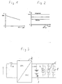
- the fuel cell system supplies a DC voltage whose magnitude depends on the current load current and other parameters, such as the current load current. Gas pressure, aging, temperature, etc. is dependent. The terminal voltage changes depending on the current in the ratio of about 1: 2.
- a typical characteristic of such a fuel cell system is shown in FIG.
- the voltage of the traction battery is dependent on the current state of charge and in the range up to the rated fuel cell current almost independent of power.
- the voltage of the driving battery changes almost in the ratio 1: 1.5 between empty battery at full load and full battery without load current.
- the battery voltage can rise to 1.4 times the operating voltage.
- the corresponding voltage / load characteristics of such a battery are shown in FIG.
- the battery Since the battery has a voltage characteristic which depends on a plurality of operating parameters and which differs from that of the fuel cell system, precaution must be taken against undesired equalizing currents. In particular, return currents from the battery to be avoided in the fuel cell system. An uncontrolled charging the battery from the fuel cell system is not desirable. Return currents from the battery into the fuel cell system are avoided in the prior art in that the fuel cell system is designed so that its output voltage is above the battery voltage. In order to avoid that due to this increased voltage level of the fuel cell system against the battery an unwanted charging current flows into the battery, this is via diodes connected, but which must be bridged in battery charging by switching devices.
- the diodes must be dimensioned so that they can carry the maximum current, ie the power required at the highest power output of the propeller motor and the supply network.
- the diodes must be bridged above a certain current with switching devices, this is technically complex and expensive.
- the invention has the object, a generic submarine with an outside air independent drive and power supply in such a way that the aforementioned disadvantages are avoided or at least reduced. It is intended below a corresponding method for operating an electrical Supply network of a submarine with fuel cell system and battery are created, which avoids the aforementioned problems.
- Claim 8 defines an inventive method for operating an electrical supply network of a submarine.
- Advantageous embodiments of the invention are specified in the subclaims, the following description and the drawing.
- the basic idea of the present invention is not to switch the fuel cell system directly parallel to the battery but to integrate it via a DC / DC controller.
- This solution according to the invention has the advantage that, on the one hand, the output voltage of the fuel cell system is arbitrarily adjustable within limits over the DC / DC controller and, on the other hand, reliable return currents from the battery or the supply network to the fuel cell system are avoided.
- the fuel cell system is galvanically isolated by the DC / DC controller for decoupling from the battery, the supply network and thus the electrical loads, so that sudden load changes must have no immediate effect on the fuel cell system.
- the DC / DC controller is a power electronic system that is capable of generating a DC output voltage which, in the specified range, can be substantially higher or lower than the DC voltage of the fuel cell system at the input of the actuator, depending on the system requirement.
- This DC / DC controller is assigned to the system in such a way that the power demanded from the system is adapted in accordance with the different voltage levels and provided primarily by the fuel cell system can. Due to the better efficiency of the fuel cell system at partial load and the chemical efficiency of the battery charge / discharge can be ensured with the help of the DC / DC controller via an appropriate regulation of the voltage that the base load is always covered by the fuel cell system, while the power peaks or sudden load jumps are covered by the battery. It is thus possible optimal use of reactants.
- the fuel cell system can be run at rated power, which then excess power can be used to charge the battery.
- the DC / DC controller is preferably associated with a current controller in a lowest control level, which ensures that in the DC / DC controller flowing current does not exceed a predetermined maximum value. Since a fuel cell system typically consists of a plurality of fuel cells connected in series to stacks and in turn connected in parallel stacks, for this current control of the lowest control level each individual channel, so each stack assign such a current regulator, so that the total current does not exceed a predetermined value. This control of the lowest control level thus effectively protects the fuel cell system from overloading.
- the DC / DC controller has a further current controller in a lower control level, which ensures that the output current of the DC / DC controller does not exceed a predetermined, preferably the maximum permissible value.
- the current controller for the output current of the DC / DC controller is advantageously superimposed on a voltage regulator, which ensures that the output voltage at the DC / DC controller does not exceed a predetermined, preferably the maximum value.
- This maximum permissible value is typically defined by the blocking capability of the output rectifier.
- a voltage regulator is primarily provided which regulates the output voltage of the DC / DC controller, for preferably 2 modes, namely normal operation and charging mode.
- the output voltage of the DC / DC controller is raised until a corresponding charging current of the battery is established.
- the control according to the invention is designed so that the fuel cell system is operated in the nominal load range.
- the voltage at the output of the DC / DC controller is controlled so that the battery current is zero or at least tends to zero.
- This regulation has the advantage that the base load of the electrical supply of the submarine in AIP operation is provided by the fuel cell system, ie a partial load range in which it is particularly favorable in terms of energy, i. works with high efficiency.
- the regulation is thus carried out so that in a sudden increase in load by an electrical load that is still covered by the fuel cell system, first the voltage at the output of the DC / DC adjuster is set so that, starting from the previous load, the voltage to a predetermined time course, which preferably corresponds to the load rise profile of the fuel cell system is raised again.
- the increase in load exceeds the power of the fuel cell system for a short or longer period of time, it is provided according to the invention to set the output voltage at the DC / DC adjuster so that the maximum permissible current for the fuel cell system is not exceeded, such that when it increases Electricity requirement of the additional partial flow is covered by the battery.
- the DC / DC controller is set or regulated to a predetermined voltage, preferably the rated voltage of the supply network.
- the DC / DC controller can then supply the on-board network as part of the capacity of the BZA alone. This regulation is intended as a so-called accidental circuit, if, for whatever reason, the battery should fail.
- the output voltage of the DC / DC controller is raised so far that at least a partial current flows into the battery.
- the voltage control is expediently carried out so that the fuel cell system is operated in the nominal load range.
- FIG. 3 The simplified illustration of the power supply for a submarine shown with reference to FIG. 3 shows a fuel cell system 1 whose electrical output is connected to the input of a DC / DC regulator 2.
- the output of the DC / DC controller 2 is parallel to a rechargeable battery 3 and forms the electrical supply network of the submarine, which consists on the one hand to power the propeller driving a motor 4 and other consumers 5 of the electrical system.
- the fuel cell system 1 is shown only symbolically and consists in a conventional manner of several fuel cell modules, in the form of stacks, which are connected in parallel, possibly in series. Each individual module / stack consists of a large number of series-connected Fuel cells. The output voltage of each fuel cell and thus also corresponding to the number of series-connected fuel cells resulting output voltage of a fuel cell module is typical.
- the battery 3 is, as usual in submarines, from a plurality of blocks connected in series to battery cells, wherein a plurality of blocks in turn may be connected in parallel.
- the construction of the DC / DC controller 2 can be seen with reference to FIGS. 4 and 5.
- the input 6 of the DC / DC controller which is electrically connected to the output of the fuel cell system, has an input capacitor C b whose capacitance is parallel to the input 6.
- an IGBT (insuleted gate bipolar transistor) converter 7 is connected, which converts the DC voltage applied to the input 6 into a high-frequency AC voltage. This is done with the help of 4 power transistors T 1 to T 4 , which in each case a freewheeling diode D 1 to D 4 is connected in anti-parallel.
- This switched by the power semiconductors T 1 to T 4 from the voltage applied to the input DC voltage is applied to the primary coil of a transformer 8, which transforms to a voltage of the appropriate height.
- This voltage applied to the secondary side of the transformer 8 AC voltage is rectified by means of a bridge rectifier 9, which is followed by an LC element consisting of current smoothing reactor 10 and capacitor C a .
- the transmitted power or the output voltage at the output 11 can be set within wide limits.
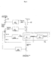
- the control is carried out as shown with reference to FIG. 6.
- the DC / DC controller 2 with the parallel-connected network (consumer 5, motor 4, Battery 3) forms the actual controlled system whose output voltage is regulated.
- a current controller 13 is provided, which controls the DC / DC controller 2, and limits the output current of the DC / DC controller 2 to a maximum value.
- the current controller 13 is superimposed on a voltage regulator 14, which ensures compliance with the maximum output voltage of the DC / DC controller 2 and thus the electrical supply of the submarine.
- This voltage regulator 14 ensures that the output voltage at the DC / DC controller 2 does not rise above the voltage permissible for the rectifier 9 in the output 11 of the DC / DC regulator 2 and thus prevents the blocking capability of the rectifier 9 from being exceeded.
- This voltage regulator 14 also allows the operation of the network with a constant voltage without a battery connected in parallel, the so-called accidental circuit 15, in which a constant voltage is predetermined and which is provided for the operation of the system in case of failure or defect of the battery 3.
- the so-called accidental circuit 15 in which a constant voltage is predetermined and which is provided for the operation of the system in case of failure or defect of the battery 3.
- the switching position shown in FIG. 6 there is only one voltage regulator for a plurality of channels connected in parallel (consisting of BZ-Strack and DC / DC controller) which transmits the same current setpoint to all channels so that a perfect parallel operation is guaranteed.
- the setpoint of the voltage regulator is limited to a maximum value.
- a battery power regulator 16 is provided, which is provided exclusively for battery charging mode.
- This controller is designed to maximize fuel cell performance to cover current power requirements. This is always the case when the battery current is zero or tends towards zero. For this, the battery current is measured and fed at 17 the battery power regulator. With the battery power regulator 16, it is thus possible to always regulate the output power of the DC / DC regulator 2, that the battery current is minimized.
- the power requirement of the system is always provided by the fuel cell system 1, at least as long as there are no sudden loads or the fuel cell system 1 has not yet reached its maximum power.
- a further current regulator 18 is provided, which compares the input current actual value of the DC / DC controller 2 with the maximum permissible current from the fuel cell system 1 and optionally regulates the fuel cell system back.
- this current regulator 18 ensures that in case of sudden power requirement, even if this would basically be covered by the fuel cell system 1, to avoid a, albeit short-term overloading of the fuel cell system 1 this is ramped up in a ramp function and the intermediate power requirement covered by the battery 3 becomes.
Claims (12)
- Sous-marin comprenant une alimentation, autonome vis-à-vis de l'atmosphère extérieure, pour la propulsion et la fourniture d'énergie, qui comporte au moins une installation de piles à combustible (1) et au moins une batterie rechargeable (3), lesquelles alimentent, par exemple, un moteur électrique (4) pour le système de propulsion ainsi que le réseau de bord (5), caractérisé en ce qu'en aval de l'installation de piles à combustible (1) est connecté un convertisseur continu-continu (2), dont la sortie (11) est connectée en parallèle sur la batterie (3).
- Sous-marin selon la revendication 1, caractérisé en ce qu'au convertisseur continu-continu (2) est associé un régulateur de courant (13), qui limite le courant de sortie du convertisseur continu-continu (2) à une valeur prédéterminée, de préférence la valeur maximale admissible.
- Sous-marin selon l'une des revendications précédentes, caractérisé en ce qu'au convertisseur continu-continu (2) est associé un régulateur de courant (18), qui limite le courant de l'installation de piles à combustible (1) à une valeur prédéterminée, de préférence à la valeur maximale admissible.
- Sous-marin selon l'une des revendications précédentes, caractérisé en ce que l'installation de piles à combustible (1) présente un ou plusieurs modules de piles à combustible montés en parallèle, un régulateur de courant étant associé à chaque module de piles à combustible, lequel régulateur de courant limite le courant d'un module de piles à combustible à une valeur prédéterminée, de préférence la valeur maximale admissible.
- Sous-marin selon l'une des revendications précédentes, caractérisé en ce qu'au convertisseur continu-continu (2) est associé un régulateur de tension, qui règle la tension de sortie en service ordinaire à la tension nominale de la batterie.
- Sous-marin selon l'une des revendications précédentes, caractérisé en ce qu'au convertisseur continu-continu (2) est associé un régulateur de tension (14), qui limite la tension de sortie à une tension prédéterminée, de préférence la tension maximale admissible.
- Sous-marin selon l'une des revendications précédentes, caractérisé en ce qu'il est prévu des dispositifs de régulation (14) qui, au cours de l'activité de charge, règlent la tension de sortie du convertisseur continu-continu (2) de telle façon que l'installation de piles à combustible (1) soit exploitée dans la plage de charge nominale.
- Procédé pour exploiter un réseau d'alimentation électrique d'un sous-marin comportant une installation de piles à combustible (1) et des batteries (3), selon lequel en aval de l'installation de piles à combustible (1) est ou sont connecté(s) un ou plusieurs convertisseur(s) continu-continu (2), la sortie étant placée respectivement (11) en parallèle sur la batterie et formant respectivement la sortie du réseau d'alimentation (5), et selon lequel, en service ordinaire, la tension de sortie de chaque convertisseur continu-continu (2) est régulée de telle façon que le courant de batterie devienne nul ou au moins tende vers zéro.
- Procédé selon la revendication 8, caractérisé en ce que ce n'est qu'après que le courant maximum admissible pour l'installation de piles à combustible (1) est atteint, que la tension de sortie sur le convertisseur continu-continu (2) est abaissée d'une manière telle, que lorsque le courant croît ensuite, un courant partiel est délivré par la batterie (3).
- Procédé selon l'une des revendications précédentes, caractérisé en ce qu'en cas de brusque accroissement de charge, le courant de l'installation de piles à combustible (1) est augmenté selon une allure prédéfinie de variation dans le temps, qui correspond de préférence au profil d'accroissement de charge de l'installation de piles à combustible (1).
- Procédé selon l'une des revendications précédentes, caractérisé en ce qu'en cas de défaillance de la batterie (3), le convertisseur continu-continu (2) est réglé/régulé à une tension prédéterminée, de préférence la tension nominale du réseau d'alimentation (5).
- Procédé selon l'une des revendications précédentes, caractérisé en ce qu'au cours de l'activité de charge, la tension de sortie du convertisseur continu-continu (2) est augmentée suffisamment pour qu'au moins un courant partiel circule dans la batterie (3).
Applications Claiming Priority (2)
| Application Number | Priority Date | Filing Date | Title |
|---|---|---|---|
| DE102004009225A DE102004009225A1 (de) | 2004-02-26 | 2004-02-26 | Unterseeboot |
| DE102004009225 | 2004-02-26 |
Publications (2)
| Publication Number | Publication Date |
|---|---|
| EP1568601A1 EP1568601A1 (fr) | 2005-08-31 |
| EP1568601B1 true EP1568601B1 (fr) | 2006-07-26 |
Family
ID=34745276
Family Applications (1)
| Application Number | Title | Priority Date | Filing Date |
|---|---|---|---|
| EP05001069A Active EP1568601B1 (fr) | 2004-02-26 | 2005-01-20 | Sous-marin avec un contrôleur CC/CC monté entre la batterie et les piles à combustible |
Country Status (4)
| Country | Link |
|---|---|
| EP (1) | EP1568601B1 (fr) |
| AT (1) | ATE334040T1 (fr) |
| DE (2) | DE102004009225A1 (fr) |
| ES (1) | ES2270392T3 (fr) |
Cited By (1)
| Publication number | Priority date | Publication date | Assignee | Title |
|---|---|---|---|---|
| DE102008026246A1 (de) * | 2008-05-30 | 2009-12-31 | Howaldtswerke-Deutsche Werft Gmbh | Verfahren zum Betrieb eines Bordstromnetzes |
Families Citing this family (4)
| Publication number | Priority date | Publication date | Assignee | Title |
|---|---|---|---|---|
| EP2062813B1 (fr) * | 2007-11-23 | 2012-07-25 | Siemens Aktiengesellschaft | Procédé et dispositif destinés à l'arrêt aussi rapide que possible des hélices entraînées électriquement d'un bateau |
| DE102013209712A1 (de) * | 2013-05-24 | 2014-11-27 | Mahle International Gmbh | Bordnetz-Anordnung für ein Kraftfahrzeug |
| FR3010960B1 (fr) | 2013-09-23 | 2017-01-27 | Cassidian Sas | Procede et systeme de gestion de l'energie a bord d'un vehicule |
| DE102014205977A1 (de) | 2014-03-31 | 2015-10-01 | Thyssenkrupp Marine Systems Gmbh | Schaltungsanordnung zur elektrischen Anbindung zumindest einer Brennstoffzellenanlage und zumindest einer wiederaufladbaren Batterie an ein Fahrnetz eines Unterwasserfahrzeugs |
Family Cites Families (6)
| Publication number | Priority date | Publication date | Assignee | Title |
|---|---|---|---|---|
| DE19810468A1 (de) * | 1998-03-11 | 1999-09-16 | Daimler Chrysler Ag | Schaltungsanordnung zur elektrischen Energieversorgung eines Netzes, das eine Brennstoffzelle sowie eine Akkumulatoranordnung aufweist |
| DE19951584B4 (de) * | 1999-10-27 | 2005-09-15 | Ballard Power Systems Ag | Vorrichtung zum Erzeugen elektrischer Energie mit einer Brennstoffzelle, der Zusatzaggregate zum Starten und zum Betrieb zugeordnet sind und Verfahren zum Betrieb der Vorrichtung |
| DE19954306B4 (de) * | 1999-11-11 | 2004-09-02 | Ballard Power Systems Ag | Vorrichtung zur elektrischen Energieerzeugnung mit einer Brennstoffzelle in einem Fahrzeug und Verfahren zum Betrieb einer derartigen Vorrichtung |
| DE10040231A1 (de) * | 2000-08-17 | 2002-02-28 | Siemens Ag | Kurzschluss-Schutzsystem für Schiffe |
| JP4292721B2 (ja) * | 2001-02-14 | 2009-07-08 | 株式会社日本自動車部品総合研究所 | ハイブリッド車の電池状態制御方法 |
| KR100412688B1 (ko) * | 2001-12-18 | 2003-12-31 | 현대자동차주식회사 | 하이브리드 전기 자동차의 배터리 충전 상태 리셋 방법 |
-
2004
- 2004-02-26 DE DE102004009225A patent/DE102004009225A1/de not_active Withdrawn
-
2005
- 2005-01-20 EP EP05001069A patent/EP1568601B1/fr active Active
- 2005-01-20 ES ES05001069T patent/ES2270392T3/es active Active
- 2005-01-20 AT AT05001069T patent/ATE334040T1/de not_active IP Right Cessation
- 2005-01-20 DE DE502005000042T patent/DE502005000042D1/de active Active
Cited By (1)
| Publication number | Priority date | Publication date | Assignee | Title |
|---|---|---|---|---|
| DE102008026246A1 (de) * | 2008-05-30 | 2009-12-31 | Howaldtswerke-Deutsche Werft Gmbh | Verfahren zum Betrieb eines Bordstromnetzes |
Also Published As
| Publication number | Publication date |
|---|---|
| DE102004009225A1 (de) | 2005-09-15 |
| EP1568601A1 (fr) | 2005-08-31 |
| ES2270392T3 (es) | 2007-04-01 |
| ATE334040T1 (de) | 2006-08-15 |
| DE502005000042D1 (de) | 2006-09-07 |
Similar Documents
| Publication | Publication Date | Title |
|---|---|---|
| EP1784910B1 (fr) | Regulateur de tension a protection contre les surtensions | |
| EP3207585B2 (fr) | Procédé de fonctionnement d'un réseau électrique, notamment d'un réseau électrique d'engin nautique | |
| DE60212818T2 (de) | Regelungsvorrichtung und verfahren für einen gleichstrom/gleichstrom-wandler | |
| DE112011105299B4 (de) | Brennstoffzellensystem | |
| EP3126182B1 (fr) | Circuit pour relier électriquement au moins un système de pile à combustible et au moins une batterie rechargeable au réseau de propulsion d'un engin sous-marin | |
| DE112008003478B4 (de) | Brennstoffzellensystem | |
| EP2758268B1 (fr) | Dispositif de commande d'un convertisseur continu-continu d'un système de propulsion électrique et procédé permettant de faire fonctionner un convertisseur continu-continu | |
| DE112011105456T5 (de) | Stromquellensystem | |
| WO2013075975A1 (fr) | Réseau de bord et procédé pour faire fonctionner un réseau de bord | |
| DE112008003996T5 (de) | Treibereinheit | |
| EP1748183B1 (fr) | Dispositif électrique de réglage des aubes de rotor d'une éolienne | |
| EP1568601B1 (fr) | Sous-marin avec un contrôleur CC/CC monté entre la batterie et les piles à combustible | |
| WO2011103987A2 (fr) | Système d'entraînement et machine de travail | |
| DE102009017023A1 (de) | Antriebssystem für eine Anlage mit einem Wechselspannungsinselnetz | |
| EP2843784A2 (fr) | Commutation d'entraînement pour un moteur monté sur coussin d'air | |
| DE112010001455T5 (de) | Brennstoffzellensystem und mit dem Brennstoffzellensystem ausgestattetes Elektrofahrzeug | |
| EP1852605A2 (fr) | Réglage du pas de pales d'une éolienne en cas de situations d'urgence | |
| WO2019025123A1 (fr) | Dispositif d'alimentation en énergie pour un véhicule ferroviaire | |
| DE102014212935A1 (de) | Vorrichtung zum Bereitstellen einer elektrischen Spannung mit seriellem Stack-Umrichter sowie Antriebsanordnung | |
| DE102013008829B4 (de) | Kraftfahrzeug | |
| DE112010001456B4 (de) | Brennstoffzellensystem und Fahrzeug, das mit dem Brennstoffzellensystem ausgestattet ist | |
| DE112011105515T5 (de) | Brennstoffzellensystem | |
| DE102007016039B4 (de) | Vorrichtung und Verfahren zur Ansteuerung einer induktiven Last | |
| DE102014016076A1 (de) | DC/DC-Wandler für ein Kraftfahrzeug | |
| WO2002065569A1 (fr) | Ensemble pile a combustible et procede pour faire fonctionner un ensemble pile a combustible |
Legal Events
| Date | Code | Title | Description |
|---|---|---|---|
| PUAI | Public reference made under article 153(3) epc to a published international application that has entered the european phase |
Free format text: ORIGINAL CODE: 0009012 |
|
| GRAP | Despatch of communication of intention to grant a patent |
Free format text: ORIGINAL CODE: EPIDOSNIGR1 |
|
| 17P | Request for examination filed |
Effective date: 20050614 |
|
| AK | Designated contracting states |
Kind code of ref document: A1 Designated state(s): AT BE BG CH CY CZ DE DK EE ES FI FR GB GR HU IE IS IT LI LT LU MC NL PL PT RO SE SI SK TR |
|
| AX | Request for extension of the european patent |
Extension state: AL BA HR LV MK YU |
|
| GRAS | Grant fee paid |
Free format text: ORIGINAL CODE: EPIDOSNIGR3 |
|
| AKX | Designation fees paid |
Designated state(s): AT BE BG CH CY CZ DE DK EE ES FI FR GB GR HU IE IS IT LI LT LU MC NL PL PT RO SE SI SK TR |
|
| GRAA | (expected) grant |
Free format text: ORIGINAL CODE: 0009210 |
|
| AK | Designated contracting states |
Kind code of ref document: B1 Designated state(s): AT BE BG CH CY CZ DE DK EE ES FI FR GB GR HU IE IS IT LI LT LU MC NL PL PT RO SE SI SK TR |
|
| PG25 | Lapsed in a contracting state [announced via postgrant information from national office to epo] |
Ref country code: IT Free format text: LAPSE BECAUSE OF FAILURE TO SUBMIT A TRANSLATION OF THE DESCRIPTION OR TO PAY THE FEE WITHIN THE PRESCRIBED TIME-LIMIT;WARNING: LAPSES OF ITALIAN PATENTS WITH EFFECTIVE DATE BEFORE 2007 MAY HAVE OCCURRED AT ANY TIME BEFORE 2007. THE CORRECT EFFECTIVE DATE MAY BE DIFFERENT FROM THE ONE RECORDED. Effective date: 20060726 Ref country code: LT Free format text: LAPSE BECAUSE OF FAILURE TO SUBMIT A TRANSLATION OF THE DESCRIPTION OR TO PAY THE FEE WITHIN THE PRESCRIBED TIME-LIMIT Effective date: 20060726 Ref country code: IE Free format text: LAPSE BECAUSE OF FAILURE TO SUBMIT A TRANSLATION OF THE DESCRIPTION OR TO PAY THE FEE WITHIN THE PRESCRIBED TIME-LIMIT Effective date: 20060726 Ref country code: FI Free format text: LAPSE BECAUSE OF FAILURE TO SUBMIT A TRANSLATION OF THE DESCRIPTION OR TO PAY THE FEE WITHIN THE PRESCRIBED TIME-LIMIT Effective date: 20060726 Ref country code: IS Free format text: LAPSE BECAUSE OF FAILURE TO SUBMIT A TRANSLATION OF THE DESCRIPTION OR TO PAY THE FEE WITHIN THE PRESCRIBED TIME-LIMIT Effective date: 20060726 Ref country code: NL Free format text: LAPSE BECAUSE OF FAILURE TO SUBMIT A TRANSLATION OF THE DESCRIPTION OR TO PAY THE FEE WITHIN THE PRESCRIBED TIME-LIMIT Effective date: 20060726 Ref country code: CZ Free format text: LAPSE BECAUSE OF FAILURE TO SUBMIT A TRANSLATION OF THE DESCRIPTION OR TO PAY THE FEE WITHIN THE PRESCRIBED TIME-LIMIT Effective date: 20060726 Ref country code: SK Free format text: LAPSE BECAUSE OF FAILURE TO SUBMIT A TRANSLATION OF THE DESCRIPTION OR TO PAY THE FEE WITHIN THE PRESCRIBED TIME-LIMIT Effective date: 20060726 Ref country code: RO Free format text: LAPSE BECAUSE OF FAILURE TO SUBMIT A TRANSLATION OF THE DESCRIPTION OR TO PAY THE FEE WITHIN THE PRESCRIBED TIME-LIMIT Effective date: 20060726 Ref country code: SI Free format text: LAPSE BECAUSE OF FAILURE TO SUBMIT A TRANSLATION OF THE DESCRIPTION OR TO PAY THE FEE WITHIN THE PRESCRIBED TIME-LIMIT Effective date: 20060726 Ref country code: PL Free format text: LAPSE BECAUSE OF FAILURE TO SUBMIT A TRANSLATION OF THE DESCRIPTION OR TO PAY THE FEE WITHIN THE PRESCRIBED TIME-LIMIT Effective date: 20060726 |
|
| REG | Reference to a national code |
Ref country code: GB Ref legal event code: FG4D Free format text: NOT ENGLISH |
|
| REG | Reference to a national code |
Ref country code: CH Ref legal event code: EP |
|
| REG | Reference to a national code |
Ref country code: IE Ref legal event code: FG4D Free format text: LANGUAGE OF EP DOCUMENT: GERMAN |
|
| REF | Corresponds to: |
Ref document number: 502005000042 Country of ref document: DE Date of ref document: 20060907 Kind code of ref document: P |
|
| GBT | Gb: translation of ep patent filed (gb section 77(6)(a)/1977) |
Effective date: 20061003 |
|
| PG25 | Lapsed in a contracting state [announced via postgrant information from national office to epo] |
Ref country code: SE Free format text: LAPSE BECAUSE OF FAILURE TO SUBMIT A TRANSLATION OF THE DESCRIPTION OR TO PAY THE FEE WITHIN THE PRESCRIBED TIME-LIMIT Effective date: 20061026 Ref country code: DK Free format text: LAPSE BECAUSE OF FAILURE TO SUBMIT A TRANSLATION OF THE DESCRIPTION OR TO PAY THE FEE WITHIN THE PRESCRIBED TIME-LIMIT Effective date: 20061026 Ref country code: BG Free format text: LAPSE BECAUSE OF FAILURE TO SUBMIT A TRANSLATION OF THE DESCRIPTION OR TO PAY THE FEE WITHIN THE PRESCRIBED TIME-LIMIT Effective date: 20061026 |
|
| PG25 | Lapsed in a contracting state [announced via postgrant information from national office to epo] |
Ref country code: PT Free format text: LAPSE BECAUSE OF FAILURE TO SUBMIT A TRANSLATION OF THE DESCRIPTION OR TO PAY THE FEE WITHIN THE PRESCRIBED TIME-LIMIT Effective date: 20061226 |
|
| NLV1 | Nl: lapsed or annulled due to failure to fulfill the requirements of art. 29p and 29m of the patents act | ||
| PG25 | Lapsed in a contracting state [announced via postgrant information from national office to epo] |
Ref country code: MC Free format text: LAPSE BECAUSE OF NON-PAYMENT OF DUE FEES Effective date: 20070131 |
|
| REG | Reference to a national code |
Ref country code: IE Ref legal event code: FD4D |
|
| ET | Fr: translation filed | ||
| REG | Reference to a national code |
Ref country code: ES Ref legal event code: FG2A Ref document number: 2270392 Country of ref document: ES Kind code of ref document: T3 |
|
| PLBE | No opposition filed within time limit |
Free format text: ORIGINAL CODE: 0009261 |
|
| STAA | Information on the status of an ep patent application or granted ep patent |
Free format text: STATUS: NO OPPOSITION FILED WITHIN TIME LIMIT |
|
| 26N | No opposition filed |
Effective date: 20070427 |
|
| BERE | Be: lapsed |
Owner name: HOWALDTSWERKE-DEUTSCHE WERFT G.M.B.H. Effective date: 20070131 |
|
| PG25 | Lapsed in a contracting state [announced via postgrant information from national office to epo] |
Ref country code: BE Free format text: LAPSE BECAUSE OF NON-PAYMENT OF DUE FEES Effective date: 20070131 |
|
| PG25 | Lapsed in a contracting state [announced via postgrant information from national office to epo] |
Ref country code: GR Free format text: LAPSE BECAUSE OF FAILURE TO SUBMIT A TRANSLATION OF THE DESCRIPTION OR TO PAY THE FEE WITHIN THE PRESCRIBED TIME-LIMIT Effective date: 20061027 |
|
| PG25 | Lapsed in a contracting state [announced via postgrant information from national office to epo] |
Ref country code: AT Free format text: LAPSE BECAUSE OF NON-PAYMENT OF DUE FEES Effective date: 20070120 |
|
| PG25 | Lapsed in a contracting state [announced via postgrant information from national office to epo] |
Ref country code: EE Free format text: LAPSE BECAUSE OF FAILURE TO SUBMIT A TRANSLATION OF THE DESCRIPTION OR TO PAY THE FEE WITHIN THE PRESCRIBED TIME-LIMIT Effective date: 20060726 |
|
| PGRI | Patent reinstated in contracting state [announced from national office to epo] |
Ref country code: IT Effective date: 20090101 |
|
| PG25 | Lapsed in a contracting state [announced via postgrant information from national office to epo] |
Ref country code: CY Free format text: LAPSE BECAUSE OF FAILURE TO SUBMIT A TRANSLATION OF THE DESCRIPTION OR TO PAY THE FEE WITHIN THE PRESCRIBED TIME-LIMIT Effective date: 20060726 Ref country code: LU Free format text: LAPSE BECAUSE OF NON-PAYMENT OF DUE FEES Effective date: 20070120 |
|
| REG | Reference to a national code |
Ref country code: CH Ref legal event code: PL |
|
| PG25 | Lapsed in a contracting state [announced via postgrant information from national office to epo] |
Ref country code: HU Free format text: LAPSE BECAUSE OF FAILURE TO SUBMIT A TRANSLATION OF THE DESCRIPTION OR TO PAY THE FEE WITHIN THE PRESCRIBED TIME-LIMIT Effective date: 20070127 Ref country code: TR Free format text: LAPSE BECAUSE OF FAILURE TO SUBMIT A TRANSLATION OF THE DESCRIPTION OR TO PAY THE FEE WITHIN THE PRESCRIBED TIME-LIMIT Effective date: 20060726 |
|
| PG25 | Lapsed in a contracting state [announced via postgrant information from national office to epo] |
Ref country code: LI Free format text: LAPSE BECAUSE OF NON-PAYMENT OF DUE FEES Effective date: 20090131 Ref country code: CH Free format text: LAPSE BECAUSE OF NON-PAYMENT OF DUE FEES Effective date: 20090131 |
|
| REG | Reference to a national code |
Ref country code: DE Ref legal event code: R082 Ref document number: 502005000042 Country of ref document: DE Representative=s name: PATENTANWAELTE VOLLMANN & HEMMER, DE |
|
| REG | Reference to a national code |
Ref country code: DE Ref legal event code: R082 Ref document number: 502005000042 Country of ref document: DE Representative=s name: PATENTANWAELTE VOLLMANN & HEMMER, DE Effective date: 20130206 Ref country code: DE Ref legal event code: R082 Ref document number: 502005000042 Country of ref document: DE Effective date: 20130206 Ref country code: DE Ref legal event code: R081 Ref document number: 502005000042 Country of ref document: DE Owner name: THYSSENKRUPP MARINE SYSTEMS GMBH, DE Free format text: FORMER OWNER: HOWALDTSWERKE-DEUTSCHE WERFT GMBH, 24143 KIEL, DE Effective date: 20130206 |
|
| REG | Reference to a national code |
Ref country code: FR Ref legal event code: CD Owner name: THYSSENKRUPP MARINE SYSTEMS GMBH Effective date: 20130313 |
|
| REG | Reference to a national code |
Ref country code: ES Ref legal event code: PC2A Owner name: THYSSENKRUPP MARINE SYSTEMS GMBH Effective date: 20130912 |
|
| REG | Reference to a national code |
Ref country code: DE Ref legal event code: R084 Ref document number: 502005000042 Country of ref document: DE |
|
| REG | Reference to a national code |
Ref country code: DE Ref legal event code: R084 Ref document number: 502005000042 Country of ref document: DE Effective date: 20150206 |
|
| REG | Reference to a national code |
Ref country code: DE Ref legal event code: R082 Ref document number: 502005000042 Country of ref document: DE |
|
| REG | Reference to a national code |
Ref country code: FR Ref legal event code: PLFP Year of fee payment: 12 |
|
| REG | Reference to a national code |
Ref country code: FR Ref legal event code: PLFP Year of fee payment: 13 |
|
| REG | Reference to a national code |
Ref country code: DE Ref legal event code: R085 Ref document number: 502005000042 Country of ref document: DE |
|
| REG | Reference to a national code |
Ref country code: FR Ref legal event code: PLFP Year of fee payment: 14 |
|
| REG | Reference to a national code |
Ref country code: DE Ref legal event code: R081 Ref document number: 502005000042 Country of ref document: DE Owner name: THYSSENKRUPP MARINE SYSTEMS GMBH, DE Free format text: FORMER OWNER: THYSSENKRUPP MARINE SYSTEMS GMBH, 24143 KIEL, DE |
|
| PGFP | Annual fee paid to national office [announced via postgrant information from national office to epo] |
Ref country code: FR Payment date: 20230124 Year of fee payment: 19 Ref country code: ES Payment date: 20230330 Year of fee payment: 19 |
|
| PGFP | Annual fee paid to national office [announced via postgrant information from national office to epo] |
Ref country code: IT Payment date: 20230120 Year of fee payment: 19 Ref country code: GB Payment date: 20230119 Year of fee payment: 19 Ref country code: DE Payment date: 20220801 Year of fee payment: 19 |
|
| PGFP | Annual fee paid to national office [announced via postgrant information from national office to epo] |
Ref country code: ES Payment date: 20240223 Year of fee payment: 20 |