EP1568591A2 - Hintere Gangschaltung für Fahrräder - Google Patents
Hintere Gangschaltung für Fahrräder Download PDFInfo
- Publication number
- EP1568591A2 EP1568591A2 EP05003063A EP05003063A EP1568591A2 EP 1568591 A2 EP1568591 A2 EP 1568591A2 EP 05003063 A EP05003063 A EP 05003063A EP 05003063 A EP05003063 A EP 05003063A EP 1568591 A2 EP1568591 A2 EP 1568591A2
- Authority
- EP
- European Patent Office
- Prior art keywords
- chain
- aforementioned
- plate
- pulley
- return section
- Prior art date
- Legal status (The legal status is an assumption and is not a legal conclusion. Google has not performed a legal analysis and makes no representation as to the accuracy of the status listed.)
- Granted
Links
- 230000002265 prevention Effects 0.000 claims description 8
- 238000000034 method Methods 0.000 claims description 5
- 230000000284 resting effect Effects 0.000 claims description 3
- 230000014759 maintenance of location Effects 0.000 claims 4
- 238000006073 displacement reaction Methods 0.000 claims 1
- 241000270281 Coluber constrictor Species 0.000 description 3
- 230000007423 decrease Effects 0.000 description 3
- OQZCSNDVOWYALR-UHFFFAOYSA-N flurochloridone Chemical compound FC(F)(F)C1=CC=CC(N2C(C(Cl)C(CCl)C2)=O)=C1 OQZCSNDVOWYALR-UHFFFAOYSA-N 0.000 description 3
- 229910000838 Al alloy Inorganic materials 0.000 description 2
- 229910052751 metal Inorganic materials 0.000 description 2
- 239000002184 metal Substances 0.000 description 2
- 150000002739 metals Chemical class 0.000 description 2
- 238000000465 moulding Methods 0.000 description 2
- 238000005452 bending Methods 0.000 description 1
- 238000010586 diagram Methods 0.000 description 1
Images


Classifications
-
- B—PERFORMING OPERATIONS; TRANSPORTING
- B62—LAND VEHICLES FOR TRAVELLING OTHERWISE THAN ON RAILS
- B62M—RIDER PROPULSION OF WHEELED VEHICLES OR SLEDGES; POWERED PROPULSION OF SLEDGES OR SINGLE-TRACK CYCLES; TRANSMISSIONS SPECIALLY ADAPTED FOR SUCH VEHICLES
- B62M9/00—Transmissions characterised by use of an endless chain, belt, or the like
- B62M9/04—Transmissions characterised by use of an endless chain, belt, or the like of changeable ratio
- B62M9/06—Transmissions characterised by use of an endless chain, belt, or the like of changeable ratio using a single chain, belt, or the like
- B62M9/10—Transmissions characterised by use of an endless chain, belt, or the like of changeable ratio using a single chain, belt, or the like involving different-sized wheels, e.g. rear sprocket chain wheels selectively engaged by the chain, belt, or the like
- B62M9/12—Transmissions characterised by use of an endless chain, belt, or the like of changeable ratio using a single chain, belt, or the like involving different-sized wheels, e.g. rear sprocket chain wheels selectively engaged by the chain, belt, or the like the chain, belt, or the like being laterally shiftable, e.g. using a rear derailleur
- B62M9/121—Rear derailleurs
- B62M9/126—Chain guides; Mounting thereof
-
- B—PERFORMING OPERATIONS; TRANSPORTING
- B62—LAND VEHICLES FOR TRAVELLING OTHERWISE THAN ON RAILS
- B62M—RIDER PROPULSION OF WHEELED VEHICLES OR SLEDGES; POWERED PROPULSION OF SLEDGES OR SINGLE-TRACK CYCLES; TRANSMISSIONS SPECIALLY ADAPTED FOR SUCH VEHICLES
- B62M9/00—Transmissions characterised by use of an endless chain, belt, or the like
- B62M9/04—Transmissions characterised by use of an endless chain, belt, or the like of changeable ratio
- B62M9/06—Transmissions characterised by use of an endless chain, belt, or the like of changeable ratio using a single chain, belt, or the like
- B62M9/10—Transmissions characterised by use of an endless chain, belt, or the like of changeable ratio using a single chain, belt, or the like involving different-sized wheels, e.g. rear sprocket chain wheels selectively engaged by the chain, belt, or the like
- B62M9/12—Transmissions characterised by use of an endless chain, belt, or the like of changeable ratio using a single chain, belt, or the like involving different-sized wheels, e.g. rear sprocket chain wheels selectively engaged by the chain, belt, or the like the chain, belt, or the like being laterally shiftable, e.g. using a rear derailleur
- B62M9/121—Rear derailleurs
- B62M9/124—Mechanisms for shifting laterally
- B62M9/1242—Mechanisms for shifting laterally characterised by the linkage mechanisms
Definitions
- the present invention relates to a derailleur, in particular to a bicycle rear derailleur which is mounted onto a bicycle frame so as to selectively derail the chain resting upon any of a multiple number of sprockets mounted onto a rear hub axis.
- An externally-mounted speed changing device is mounted onto a bicycle, especially onto a sports-type road racer or mountain bike.
- Such rear derailleur is equipped with a base component, which is mounted on the frame; a link mechanism, one end of which is mounted on the base component; a movable component, which is mounted on the other end of the link mechanism, and which can be relatively displaced from the aforementioned base component; and a chain guide, which is mounted on the movable component so as to undulate like a see-saw.
- the chain guide functions to transfer the chain, so as to derail the chain upon any of the rear sprockets.
- the chain guide is equipped with an outer plate, which is mounted on the movable component so as to undulate like a see-saw; an inner plate, which is installed so as to face the outer plate; a guide pulley, which is mounted onto a portion on one edge of the plates, between the plates, so as to freely rotate, and which can be engaged by means of the chain; and a tension pulley, which can be engaged with the aforementioned chain, and which is mounted onto a portion on the other edge of the aforementioned plates, between the plates, so as to freely rotate.
- the purpose of the present invention is to achieve a return of the chain to the tension pulley more easily through pedaling actions when the chain falls off from the tension pulley.
- a Bicycle rear derailleur which is mounted onto a bicycle frame in order to selectively derail the chain resting upon any of a multiple number of sprockets mounted onto a rear hub axis, and which is equipped with a base component, a link mechanism, a movable component, an outer plate, an inner plate, a guide pulley, and a tension pulley.
- the base component is mounted onto the frame.
- One end of the link mechanism is mounted onto the base component.
- the movable component is mounted onto the other end of the link mechanism, and can be relatively displaced from the base component.
- the outer plate is mounted unto the movable component so as to undulate like a see-saw.
- the inner plate is installed so as to face the outer plate.
- the guide pulley is mounted onto a portion on one edge of the plates, between the plates, so as to freely rotate and freely move in the axial direction, and can be engaged by means of the chain.
- the tension pulley can be engaged with the chain, and is mounted onto a portion on the other edge of the plates, between the plates, so as to freely rotate.
- the chain return section is installed at a position on the inner plate which is proximal to the position at which the tension pulley is mounted, in a manner so that the clearance from the chain at this position is narrower as compared to the clearance at other positions.
- the chain return section is formed at the portion close to the tension pulley on the inner plate as a protrusion, so that the clearance from the chain at this portion is narrower than at other portions, even when the chain falls off from the tension pulley, when the chain is continuously rotated by means of pedaling action, the link component of the chain is pressed by the chain return section; consequently, the chain can be returned to the tension pulley more easily. Therefore, even when the chain has fallen off from the tension pulley, the chain can be returned to the tension pulley by means of pedaling action.
- the chain return section is structured by means of a protrusion which is formed thicker than at other portions at the aforementioned position on the inner plate. More preferably, the chain return section is structured simply by forming a protrusion on the inner plate. Such a chain return section can be obtained at low cost.
- the inner plate is equipped with two arms, which extend from the position onto which the tension pulley is mounted, and an arch, which has a circular-arc shape and which connects the arms; and a chain return section, which is installed on the circular-arc shaped arch.
- the chain return section is installed on the circular-arc shaped arch, such that the area which comes into contact with the chain becomes larger; therefore, the chain can be returned to the tension pulley more easily.
- the arch is positioned in the area extending downward from and rearward of the position at which the tension pulley is mounted, and the chain return section is formed at the position which becomes the downstream when the pedals are pushed, in the area of the arch which faces the chain.
- the chain return section is installed at the downstream of the arch, the chain which has fallen off comes into contact with the chain return section when the pedals are pushed. Therefore, the chain becomes inclined to the tension pulley more easily, and thus, is more easily caught by the tension pulley.
- the inner plate is further equipped with a chain falling-off prevention mechanism, which extends in the direction of the outer plate, and the chain return section is installed at a position proximal to the chain falling-off prevention mechanism. It is particularly preferred that the chain falling-off prevention mechanism is installed at a position proximal to the chain return section, such that the chain is less likely to fall off from the tension pulley, wherein even if it falls off, it can be returned to the tension pulley more easily.
- the chain return section is formed as a protrusion at the portion close to the tension pulley on the inner plate, so that the clearance from the chain at this portion is narrower than at other portions, even when the chain falls off from the tension pulley, when the chain is continuously rotated by means of pedaling action, the link component of the chain is pressed by the chain return section; consequently the chain can be returned to the tension pulley more easily. Therefore, even when the chain has fallen off from the tension pulley, the chain can be returned to the tension pulley by means of pedaling action.
- Bicycle 101 to which a preferred embodiment of the present invention is applied, is a road racer.
- the bicycle is equipped with diamond-shaped Frame 102, which is equipped with Front Fork 98; Handle 104, which is affixed to Front Fork 98; Driver 105, which consists of Crank 96 equipped with Chain 95, pedals PD, and other components, Front and Rear Deraille 97f and 97r, Front and Rear Sprocket Blocks 99f and 99r, and other parts; Front and Rear Wheels 106f and 106r, which are mounted on Front Fork 98 and the rear portion of Frame 102; along with Front and Rear Brakes 107f and 107r, and Gear Shifters 110f and 110r, which control the shifting of gears of the Front and Rear Deraille 97f and 97r.
- Handle 104 is structured by means of Handle Stem 111 and Handle Bar 112, which is joined together with and affixed to the upper portion of Handle Stem 111.
- Handle Stem 111 is joined together with and fixated onto the upper portion of the Front Fork 98.
- Drop-handle type Handle Bar 112 is equipped with a pair of right and left Brake Levers 113f and 113r. Onto these Brake Bars 113f and 113r, Gear Shifters 110f and 110r are mounted. Gear Shifters 110f and 110r are connected to Front and Rear Derailleurs 97f and 97r by means of Gear Cables 115fand 115r.
- Driver 105 includes Chain 95; Front and Rear Derailleur 97f and 97r, which derail Chain 95 onto different gears; and Front and Rear Sprocket Blocks 99f and 99r.
- Front Derailleur 97f is installed on Seat Tube 102a of Frame 102, and is set at two gears by Gear Shifter 110f so as to guide Chain 95.
- Rear Derailleur 97r is installed on Rear Fork End 102b of Frame 102, and is set at ten gears by Gear Shifter 110f so as to guide Chain 95.
- Front Sprocket Block 99f is equipped with two Sprockets F1 and F2, which are arranged in a line in the axial direction of the crank shaft, and which have different numbers of teeth.
- Rear Sprocket Block 99r is equipped with ten Sprockets R1 to R10, which are arranged in a line in the axial direction along with Hub Axis 106a of the rear wheel, and which have different numbers of teeth.
- inner Sprocket F1 has fewer teeth than does outer Sprocket F2.
- the number of teeth gradually decreases as the sprockets advance from innermost Sprocket R1; the outermost top Sprocket R10 has the fewest number of teeth.
- Front and Rear Deraille 97f and 97r derail Chain 95 onto either one of the multiple Sprockets, F1 and F2, and R1 to R10, in order to shift gears.
- This gear shift is conducted by Gear Shifters 110f and 110r, by utilizing Brake Levers 113f and 113r.
- Rear Derailleur 97r is mounted onto Rear Fork End 102b, formed on the rear portion of Frame 102; it selectively derails Chain 95 upon either one of the multiple Sprockets R1 to R10 in Rear Sprocket Block 99r.
- Rear Derailleur 97r is equipped with Base Component 10, which is screwed into and mounted onto Fork End 102b; Link Mechanism 11, one end of which is mounted onto Base Component 10; Movable Component 12, which is mounted onto another end of Link Mechanism 11 and which can be relatively displaced from Base Component 10; and Chain Guide 13, which is mounted unto Movable Component 12 so as to undulate like a see-saw. Chain Guide 13 functions to shift Chain 95, so that Chain 95 becomes derailed upon any of Sprockets R1 to R10.
- Base Component 10 is equipped with Boss 10a, which is cylindrical in shape, and which is screwed into Fork End 102b of Frame 102; as well as Arm 10b, which extends from Boss 10a in the radial direction.
- Boss 10a which is cylindrical in shape, and which is screwed into Fork End 102b of Frame 102; as well as Arm 10b, which extends from Boss 10a in the radial direction.
- Link Supporter 10c which functions to mount Link Mechanism 11, is formed.
- Outer Latch 10d which functions to latch Outer Casing 115b of Gear Cable 115r, is formed.
- Link Mechanism 11 is a four-point link mechanism, in which Movable Component 12 is connected to Base Component 10 in such a manner that Movable Component 12 may be relatively displaced from Base Component 10.
- Link Mechanism 11 is equipped with External Link Component 11a and Internal Link Component 11b, one end of which is mounted to the lower edge of Base Component 10 through Link Supporter 10c so as to undulate like a see-saw.
- the other end of these Link Components 11a and 11b is mounted to Link Supporter 12a of Movable Component 12 (stated later), so as to undulate like a see-saw.
- Link Components 11a and 11b are energized by means of coil springs (not shown in the figures), installed so that they mutually face each other towards the smallest diameter Sprocket R10.
- Inner Latch 11c On External Link Component 11 a, Inner Latch 11c, which functions to latch Inner Cable 115a of Gear Cable 115r, is formed.
- Movable Component 12 functions to mount Chain Guide 13 on an axis substantially parallel to Hub Axis 106a of Rear Wheel 106r, so as to undulate like a see-saw.
- Movable Component 12 is equipped with Link Supporter 12a, on which both Link Components 11a and 11b of the Link Mechanism are mounted so as to undulate like a see-saw.
- Movable Component 12 is also equipped with Guide Mounting Unit 12b, on which Chain Guide 13 is mounted so as to undulate like a see-saw.
- a torsion coil spring (not shown in Figures) is mounted, and Chain Guide 13 is energized by means of the torsion coil spring in a clockwise direction, as seen from the outside. With this structure, tension is placed onto Chain 95, so that Chain 95 is less likely to fall off from Sprockets R1 to R10.
- Chain Guide 13 is equipped with Outer Plate 20, which is mounted on Movable Component 12 so as to undulate like a see-saw; Inner Plate 21, which is installed so as to face Outer Plate 20; Guide Pulley 22, which is mounted onto a portion on one edge of Outer Plate 20 and Inner Plate 21, between the plates, so as to freely rotate and move in the axial direction, and which can be engaged with the chain; and Tension Pulley 23, which can be engaged with Chain 95, and which is mounted onto a portion on the other edge of Outer Plate 20 and Inner Plate 21, between the plates, so as to freely rotate.
- Outer Plate 20 is a component which is formed by the press-molding of light-weight metals, such as aluminum alloy.
- Figure 6 is a view of Outer Plate 20 as seen from the inside. The lower end of Outer Plate 20 slightly curves outwards as compared to the other end.
- Undulation Supporter 20a which is mounted onto Movable Component 12 so as to undulate like a see-saw, is formed.
- First Boss 20b which supports Guide Pulley 22 in a freely rotatable manner, is formed.
- Female Screw 20c into which Supporting Axis 30 of Guide Pulley 22 is screwed, is formed.
- Second Boss 20d which supports Tension Pulley 23 in a freely rotatable manner, is formed.
- Second Boss 20d Pass-through Hole 20e, through which Supporting Axis 31 which supports Tension Pulley 23 passes, is formed.
- Second Boss 20d is positioned at a position offset outwards from First Boss 20b by Distance L1. This Distance L1 lies in a range from 1mm to 1.5mm, and is preferably approximately 1.25mm.
- Inner Plate 21 is a component which is formed by the press-molding of light-weight metals, such as aluminum alloy.
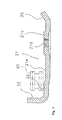
- Figure 8 is a view of Inner Plate 21 as seen from the outside.
- First Boss 21 a is formed at a position facing First Boss 20b of Outer Plate 20.
- First Boss 21a Pass-through Hole 21b, through which Supporting Axis 30 supporting Guide Pulley 22 passes, is formed.
- Second Boss 21c which supports Tension Pulley 23 in a freely rotatable manner, is formed.
- Second Boss 21c Female Screw 21d, into which Supporting Axis 31 which supports Tension Pulley 23 is screwed, is formed.
- First Boss 21a and Second Boss 21c are formed so as to be positioned on the same plane.
- Chain Return Section 32 is formed.
- Chain Return Section 32 is formed in order to assist the chain to return to Tension Pulley 23 through pedaling action when the tension placed on Chain 95 becomes weaker and Chain 95 falls off.
- Chain Return Section 32 is formed in such a manner that the clearance from Chain 95 is narrower at the position proximal to Second Boss 21 c, onto which Tension Pulley 23 is mounted, as compared to the clearance at other portions.
- Chain Return Section 32 is structured by a protrusion which is formed thicker than at other portions on Arch 21 g.
- Chain Falling-off Prevention Mechanism 33 On the rear portion of Chain Return Section 32, Chain Falling-off Prevention Mechanism 33, which is formed by bending the portion outwards, is installed. Chain Falling-off Prevention Mechanism 33 is installed in order to prevent Chain 95 from falling off from Tension Pulley 23. Specifically, this mechanism prevents Chain 95 from falling off backwards.
- Contact Prevention Mechanism 34 On the front of Chain Return Section 32, Contact Prevention Mechanism 34, which prevents Inner Plate 21 from coming into contact with the spoke of Rear Wheel 106r when it undulates forwards, is installed.
- Guide Pulley 22 is capable of aligning the engagement center of Chain 95 to the engagement center of any of Sprockets R1 to R10, and is installed in order to guide Chain 95 to any of Sprockets R1 to R10.
- Guide Pulley 22 is mounted onto Supporting Axis 30 by means of a ball bearing (not shown in Figures) in a freely rotatable manner. As illustrated in Figure 10, the Guide Pulley is mounted between First Bosses 20b and 21 a. Clearance L4 between First Bosses 20b and 21a is set wider by 1mm to 1.5mm than the maximum width of Guide Pulley 22. Therefore, Guide Pulley 22 is mounted onto Supporting Axis 30 so as to move in the axial direction by a maximum of 1.5mm.
- Tension Pulley 23 is installed in order to apply tension to Chain 95.
- Tension Pulley 23 is mounted onto Supporting Axis 31 by means of a ball bearing (not shown in the figures) in a freely rotatable manner.
- a ball bearing not shown in the figures
- Tension Pulley 23 is deflected towards Second Boss 20d, and is arranged so that it cannot move in the axial direction. Therefore, as an example, two Washers 35 and 36 are mounted between Second Boss 21c and Tension Pulley 23.
- Chain Return Section 32 is formed as a protrusion so that the clearance from Chain 95 at this portion is narrower than at other portions, and Chain 95 is pressed by means of Chain Return Section 32 when Chain 95 travels towards Guide Pulley 22 by means of pedaling action. Because of this, the position of Chain 95 is corrected outwards, becomes inclined towards Tension Pulley 23, and thus is caught by Tension Pulley 23 more easily. As a result, Chain 95, which has fallen off from Tension Pulley 23, can be returned more easily without stopping Bicycle 101.
- a manually-operated rear derailleur for a road racer was described.
- the present invention is not limited to this example, and can be applied to any rear derailleur, as long as it is equipped with a guide pulley and a tension pulley. It may also be electrically operated.
- the chain return section is structured as a protrusion formed on the inner plate.
- other objects may be affixed on the inner plate so as to directly make contact with the chain.
Landscapes
- Engineering & Computer Science (AREA)
- Chemical & Material Sciences (AREA)
- Combustion & Propulsion (AREA)
- Transportation (AREA)
- Mechanical Engineering (AREA)
- Devices For Conveying Motion By Means Of Endless Flexible Members (AREA)
- Transmissions By Endless Flexible Members (AREA)
Applications Claiming Priority (2)
| Application Number | Priority Date | Filing Date | Title |
|---|---|---|---|
| JP2004051492 | 2004-02-26 | ||
| JP2004051492A JP3819396B2 (ja) | 2004-02-26 | 2004-02-26 | 自転車用リアディレーラ |
Publications (3)
| Publication Number | Publication Date |
|---|---|
| EP1568591A2 true EP1568591A2 (de) | 2005-08-31 |
| EP1568591A3 EP1568591A3 (de) | 2006-09-13 |
| EP1568591B1 EP1568591B1 (de) | 2010-01-13 |
Family
ID=34747506
Family Applications (1)
| Application Number | Title | Priority Date | Filing Date |
|---|---|---|---|
| EP05003063A Ceased EP1568591B1 (de) | 2004-02-26 | 2005-02-14 | Hintere Gangschaltung für Fahrräder |
Country Status (6)
| Country | Link |
|---|---|
| US (1) | US7318784B2 (de) |
| EP (1) | EP1568591B1 (de) |
| JP (1) | JP3819396B2 (de) |
| CN (1) | CN100464091C (de) |
| DE (1) | DE602005018850D1 (de) |
| TW (1) | TWI237615B (de) |
Cited By (2)
| Publication number | Priority date | Publication date | Assignee | Title |
|---|---|---|---|---|
| EP1939086A1 (de) * | 2006-12-26 | 2008-07-02 | Shimano Inc. | Hinterradkettenschaltung für ein Fahrrad |
| US9005060B2 (en) | 2010-10-06 | 2015-04-14 | Zike, Llc | Derailleur |
Families Citing this family (14)
| Publication number | Priority date | Publication date | Assignee | Title |
|---|---|---|---|---|
| US7666111B2 (en) * | 2005-07-19 | 2010-02-23 | Shimano Inc. | Bicycle rear derailleur |
| JP2009056969A (ja) * | 2007-08-31 | 2009-03-19 | Shimano Inc | 自転車用リアディレーラ |
| US10207772B2 (en) | 2011-01-28 | 2019-02-19 | Paha Designs, Llc | Gear transmission and derailleur system |
| US9033833B2 (en) | 2011-01-28 | 2015-05-19 | Paha Designs, Llc | Gear transmission and derailleur system |
| US9327792B2 (en) | 2011-01-28 | 2016-05-03 | Paha Designs, Llc | Gear transmission and derailleur system |
| DE102012013645B4 (de) * | 2012-07-09 | 2023-03-23 | Sram Deutschland Gmbh | Hinterer Umwerfer für eine Kettenschaltung eines Fahrrads und Kettenführungsrolle für einen derartigen hinteren Umwerfer |
| US9623932B2 (en) * | 2014-12-10 | 2017-04-18 | Shimano Inc. | Bicycle derailleur |
| CN105000088A (zh) * | 2015-07-02 | 2015-10-28 | 谢娟 | 一种山地车导向轮安装块 |
| US11319021B2 (en) * | 2017-08-23 | 2022-05-03 | Shimano Inc. | Bicycle rear derailleur |
| TWI647146B (zh) * | 2017-11-10 | 2019-01-11 | 台灣微轉股份有限公司 | 自行車後變速器 |
| US11148755B2 (en) * | 2018-07-13 | 2021-10-19 | Shimano Inc. | Bicycle derailleur |
| TWI789225B (zh) * | 2022-01-27 | 2023-01-01 | 台灣微轉股份有限公司 | 自行車前撥鏈器 |
| USD1025842S1 (en) * | 2022-11-11 | 2024-05-07 | Lal Bikes, Inc. | Bicycle derailleur |
| TWI875504B (zh) * | 2024-03-06 | 2025-03-01 | 傳誠技研有限公司 | 自行車之導鏈器 |
Citations (1)
| Publication number | Priority date | Publication date | Assignee | Title |
|---|---|---|---|---|
| JPH0210075U (de) | 1988-06-25 | 1990-01-23 |
Family Cites Families (17)
| Publication number | Priority date | Publication date | Assignee | Title |
|---|---|---|---|---|
| US2598557A (en) * | 1944-03-22 | 1952-05-27 | Juy Lucien Charles Hippolyte | Variable-speed gear |
| FR1319997A (fr) * | 1962-04-20 | 1963-03-01 | Changement de vitesse par déraillement de chaîne, en éléments combinés en matière plastique et en métal pour cycles, tandems, vélomoteurs, motocyclettes ou véhicules similaires | |
| FR2213864B1 (de) * | 1973-01-15 | 1977-07-29 | Huret Roger | |
| JPS5457736A (en) * | 1977-10-14 | 1979-05-09 | Maeda Ind | Sheath transmission for bicycle |
| US4575265A (en) * | 1980-05-27 | 1986-03-11 | Reliance Electric Company | Seal for shaft bearings |
| FR2520693B1 (fr) * | 1982-02-03 | 1990-01-12 | Simplex Ets | Guide-chaine a galets pour les changements de vitesse arriere des cycles et vehicules similaires |
| US4530677A (en) * | 1983-02-22 | 1985-07-23 | Shimano Industrial Company Limited | Derailleur for a bicycle |
| US4575365A (en) | 1983-08-02 | 1986-03-11 | Shimano Industrial Company Limited | Rear derailleur for a bicycle |
| CA1236995A (en) | 1984-02-16 | 1988-05-24 | Shizuo Nakamura | Bicycle rear derailleur |
| US4637809A (en) * | 1984-11-30 | 1987-01-20 | Shimano Industrial Company Limited | Rear derailleur for a bicycle |
| IT215965Z2 (it) * | 1988-09-30 | 1991-03-20 | Perotti Ofmega Snc | Deragliatore di catena per cambi di velocita' di biciclette. |
| USD424984S (en) * | 1998-02-09 | 2000-05-16 | Shimano Inc. | Bicycle derailleur |
| IT1307681B1 (it) * | 1999-04-13 | 2001-11-14 | Campagnolo Srl | Deragliatore posteriore di bicicletta. |
| US6287228B1 (en) * | 1999-11-12 | 2001-09-11 | Shimano, Inc. | Rear derailleur with cable guide roller |
| ITTO20001124A1 (it) * | 2000-12-01 | 2002-06-01 | Campagnolo Srl | Gruppo bilanciere per il deragliatore posteriore di una bicicletta. |
| US20030083162A1 (en) * | 2001-10-26 | 2003-05-01 | Sunrace Roots Enterprise Co., Ltd. | Rear derailleur of a bicycle |
| CN1329241C (zh) * | 2002-03-08 | 2007-08-01 | 株式会社岛野 | 自行车用后拨链器 |
-
2004
- 2004-02-26 JP JP2004051492A patent/JP3819396B2/ja not_active Expired - Fee Related
- 2004-06-17 US US10/871,746 patent/US7318784B2/en not_active Expired - Fee Related
- 2004-07-21 TW TW093121786A patent/TWI237615B/zh not_active IP Right Cessation
- 2004-08-30 CN CNB2004100748682A patent/CN100464091C/zh not_active Expired - Fee Related
-
2005
- 2005-02-14 EP EP05003063A patent/EP1568591B1/de not_active Ceased
- 2005-02-14 DE DE602005018850T patent/DE602005018850D1/de not_active Expired - Lifetime
Patent Citations (1)
| Publication number | Priority date | Publication date | Assignee | Title |
|---|---|---|---|---|
| JPH0210075U (de) | 1988-06-25 | 1990-01-23 |
Cited By (2)
| Publication number | Priority date | Publication date | Assignee | Title |
|---|---|---|---|---|
| EP1939086A1 (de) * | 2006-12-26 | 2008-07-02 | Shimano Inc. | Hinterradkettenschaltung für ein Fahrrad |
| US9005060B2 (en) | 2010-10-06 | 2015-04-14 | Zike, Llc | Derailleur |
Also Published As
| Publication number | Publication date |
|---|---|
| EP1568591A3 (de) | 2006-09-13 |
| US7318784B2 (en) | 2008-01-15 |
| JP2005238980A (ja) | 2005-09-08 |
| TWI237615B (en) | 2005-08-11 |
| CN100464091C (zh) | 2009-02-25 |
| DE602005018850D1 (de) | 2010-03-04 |
| JP3819396B2 (ja) | 2006-09-06 |
| CN1660656A (zh) | 2005-08-31 |
| US20050192141A1 (en) | 2005-09-01 |
| EP1568591B1 (de) | 2010-01-13 |
| TW200528347A (en) | 2005-09-01 |
Similar Documents
| Publication | Publication Date | Title |
|---|---|---|
| EP1568592B1 (de) | Hinterradkettenschaltung für ein Fahrrad | |
| EP1568591B1 (de) | Hintere Gangschaltung für Fahrräder | |
| US10604212B2 (en) | Bicycle rear derailleur with a motion resisting structure | |
| EP1955941B1 (de) | Hinterradkettenschaltung für ein Fahrrad | |
| EP2030889B1 (de) | Hinterradkettenschaltung für ein Fahrrad | |
| EP1961652B1 (de) | Betätigungsvorrichtung für eine Fahrradgangschaltung | |
| EP2357127B1 (de) | Fahrradbrems- und Gangschaltungsbetätigungsvorrichtung | |
| EP1818254B1 (de) | Vorderer Kettenumwerfer für ein Fahrrad | |
| US7527571B2 (en) | Rear derailleur for bicycle | |
| EP1582449A2 (de) | Umwerfer für ein Fahrrad | |
| US7125354B2 (en) | Bicycle derailleur with a chain guide disposed at an upper portion of a link mechanism | |
| EP1762482B1 (de) | Vorrichtung zur Verhinderung des Lösens einer Kette für vordere Umwerfer | |
| US7806792B2 (en) | Auxiliary bicycle shifting component |
Legal Events
| Date | Code | Title | Description |
|---|---|---|---|
| PUAI | Public reference made under article 153(3) epc to a published international application that has entered the european phase |
Free format text: ORIGINAL CODE: 0009012 |
|
| AK | Designated contracting states |
Kind code of ref document: A2 Designated state(s): AT BE BG CH CY CZ DE DK EE ES FI FR GB GR HU IE IS IT LI LT LU MC NL PL PT RO SE SI SK TR |
|
| AX | Request for extension of the european patent |
Extension state: AL BA HR LV MK YU |
|
| RAP1 | Party data changed (applicant data changed or rights of an application transferred) |
Owner name: SHIMANO INC. |
|
| PUAL | Search report despatched |
Free format text: ORIGINAL CODE: 0009013 |
|
| AK | Designated contracting states |
Kind code of ref document: A3 Designated state(s): AT BE BG CH CY CZ DE DK EE ES FI FR GB GR HU IE IS IT LI LT LU MC NL PL PT RO SE SI SK TR |
|
| AX | Request for extension of the european patent |
Extension state: AL BA HR LV MK YU |
|
| 17P | Request for examination filed |
Effective date: 20061017 |
|
| 17Q | First examination report despatched |
Effective date: 20061127 |
|
| AKX | Designation fees paid |
Designated state(s): DE IT |
|
| GRAP | Despatch of communication of intention to grant a patent |
Free format text: ORIGINAL CODE: EPIDOSNIGR1 |
|
| GRAS | Grant fee paid |
Free format text: ORIGINAL CODE: EPIDOSNIGR3 |
|
| GRAA | (expected) grant |
Free format text: ORIGINAL CODE: 0009210 |
|
| AK | Designated contracting states |
Kind code of ref document: B1 Designated state(s): DE IT |
|
| REF | Corresponds to: |
Ref document number: 602005018850 Country of ref document: DE Date of ref document: 20100304 Kind code of ref document: P |
|
| PLBE | No opposition filed within time limit |
Free format text: ORIGINAL CODE: 0009261 |
|
| STAA | Information on the status of an ep patent application or granted ep patent |
Free format text: STATUS: NO OPPOSITION FILED WITHIN TIME LIMIT |
|
| 26N | No opposition filed |
Effective date: 20101014 |
|
| PGFP | Annual fee paid to national office [announced via postgrant information from national office to epo] |
Ref country code: IT Payment date: 20170221 Year of fee payment: 13 |
|
| PG25 | Lapsed in a contracting state [announced via postgrant information from national office to epo] |
Ref country code: IT Free format text: LAPSE BECAUSE OF NON-PAYMENT OF DUE FEES Effective date: 20180214 |
|
| PGFP | Annual fee paid to national office [announced via postgrant information from national office to epo] |
Ref country code: DE Payment date: 20200204 Year of fee payment: 16 |
|
| REG | Reference to a national code |
Ref country code: DE Ref legal event code: R119 Ref document number: 602005018850 Country of ref document: DE |
|
| PG25 | Lapsed in a contracting state [announced via postgrant information from national office to epo] |
Ref country code: DE Free format text: LAPSE BECAUSE OF NON-PAYMENT OF DUE FEES Effective date: 20210901 |