EP1568582A2 - Workstation for assembling workpieces in an automotive assembly line - Google Patents
Workstation for assembling workpieces in an automotive assembly line Download PDFInfo
- Publication number
- EP1568582A2 EP1568582A2 EP05003974A EP05003974A EP1568582A2 EP 1568582 A2 EP1568582 A2 EP 1568582A2 EP 05003974 A EP05003974 A EP 05003974A EP 05003974 A EP05003974 A EP 05003974A EP 1568582 A2 EP1568582 A2 EP 1568582A2
- Authority
- EP
- European Patent Office
- Prior art keywords
- processing
- material handling
- workpiece
- handling robot
- workstation
- Prior art date
- Legal status (The legal status is an assumption and is not a legal conclusion. Google has not performed a legal analysis and makes no representation as to the accuracy of the status listed.)
- Withdrawn
Links
Images

Classifications
-
- B—PERFORMING OPERATIONS; TRANSPORTING
- B62—LAND VEHICLES FOR TRAVELLING OTHERWISE THAN ON RAILS
- B62D—MOTOR VEHICLES; TRAILERS
- B62D65/00—Designing, manufacturing, e.g. assembling, facilitating disassembly, or structurally modifying motor vehicles or trailers, not otherwise provided for
- B62D65/02—Joining sub-units or components to, or positioning sub-units or components with respect to, body shell or other sub-units or components
-
- B—PERFORMING OPERATIONS; TRANSPORTING
- B23—MACHINE TOOLS; METAL-WORKING NOT OTHERWISE PROVIDED FOR
- B23K—SOLDERING OR UNSOLDERING; WELDING; CLADDING OR PLATING BY SOLDERING OR WELDING; CUTTING BY APPLYING HEAT LOCALLY, e.g. FLAME CUTTING; WORKING BY LASER BEAM
- B23K37/00—Auxiliary devices or processes, not specially adapted to a procedure covered by only one of the preceding main groups
- B23K37/04—Auxiliary devices or processes, not specially adapted to a procedure covered by only one of the preceding main groups for holding or positioning work
- B23K37/047—Auxiliary devices or processes, not specially adapted to a procedure covered by only one of the preceding main groups for holding or positioning work moving work to adjust its position between soldering, welding or cutting steps
Landscapes
- Engineering & Computer Science (AREA)
- Mechanical Engineering (AREA)
- Manufacturing & Machinery (AREA)
- Chemical & Material Sciences (AREA)
- Combustion & Propulsion (AREA)
- Transportation (AREA)
- Physics & Mathematics (AREA)
- Optics & Photonics (AREA)
- Manipulator (AREA)
- Automatic Assembly (AREA)
- Resistance Welding (AREA)
Abstract
In particular, a welding workstation for automotive assembly lines is provided.
Description
- The present application claims the benefit of provisional application serial number 60/548,129 filed on February 26, 2004 and serial number 60/618,422 filed on October 13, 2004.
- The present invention relates to a flexible body workstation for assembling workpieces using multiple robots and multiple fixtures, and more specifically, the present invention provides welding workstations for automotive assembly lines having multiple independently working welding robots and multiple fixtures for holding workpieces.
- The efficiency of a welding workstation can be defined by the amount of time, normally a percentage, that a welding robot spends welding compared to the total time required for a particular repetitive cycle. The efficiency of the workstation relates to the amount of time that a welding robot takes to perform various welding operations compared to the total amount of time that the welding robot requires for a particular repetitive cycle. Idle time for a welding robot can occur when a new workpiece is loaded and prepared in a fixture. If the workstation has one welding robot and one fixture, the welding robot will stand idle as a completed part is unloaded from the fixture and a new workpiece is loaded onto the fixture. In the prior art, this problem was addressed by adding a second fixture at the workstation within reach of a single welding robot. In a workstation with two fixtures, the welding robot can complete welding operations at one fixture while workpieces are being loaded and unloaded at the second fixture. When the welding process is complete at the first fixture, the welding robot can move to the second fixture and immediately commence welding.
- The amount of time that a workpiece is positioned in a fixture while work is being performed compared to the total amount of time that a workpiece is positioned in a fixture corresponds to workpiece efficiency. The amount of time that a workpiece sits idle in a fixture reduces the overall operating capacity of the workstation by reducing throughput, normally reported in parts per hour or similar units for the overall assembly process. In a workstation having one fixture and one welding robot, the amount of time that a workpiece sits idle in the fixture is minimized because the welding robot immediately commences welding operations as soon as a workpiece is loaded and any other setup procedures are completed. However, in a workstation that has two fixtures and one welding robot, a workpiece is loaded onto one fixture, is setup, and then sits idle until the welding robot completes welding operations at the second fixture. Therefore, in a workstation having one fixture and one welding robot, the workpiece efficiency is maximized while in a workstation having two fixtures and one welding robot the welding efficiency is maximized. It is desirable to provide a workstation wherein the welding efficiency and the workpiece efficiency are both enhanced.
- The present invention can include a single or a plurality of similar workstations positioned in sequence along an assembly line. A movable material handling transportation or transfer robot can be located in between adjacent workstations for moving workpieces from one workstation to the next. The present invention can also include a robot for processing the workpieces while held by the material handling transfer robot in between the adjacent workstations.
- The present invention includes a flexible body shop for assembling workpieces using a single or multiple robots and a single or multiple fixtures. The present invention includes movable material handling robots, and stationary material processing robots in combination at the flexible body workstation. The workstation can perform processing operations on multiple workpieces sequentially, and performs different processing operations through the workstation simultaneously. The material processing robots performing processing operations on the workpieces can be located adjacent the at least one processing path, or in between first and second processing paths and are independently movable relative to each other. The workpiece fixtures can be provided in the form of interchangeable end effecters connectible to the at least one material handling robot for holding and supporting different workpiece configurations by exchanging one interchangeable end effecter configuration for a different interchangeable end effecter workpiece configuration. The interchangeable end effecters can be geometry fixtures for different workpiece configurations to allow processing different workpiece configurations in any desired sequence by changing end effecters automatically to correspond to the next workpiece configuration to be processed.
- The present invention can include a plurality of similar workstations positioned in sequence along an assembly line. The at least one material handling robot can hand off a workpiece from a transfer position at one end of the processing path to another material handling robot for movement along another processing path for moving workpieces from one workstation to the next and/or can position a workpiece at multiple workstations before transfer. The present invention can also include a material processing robot for processing the workpiece while being held by the material handling robot at the transfer position in between adjacent workstations.
- The present invention can provide an electronic control means for coordinating the movement of the material handling robots and/or the material processing robots. The electronic control means can be programmable for processing any mix of workpieces of different configurations in any sequential order. The electronic control means can present the appropriate interchangeable end effecter for connection to a material handling robot in order to move the workpiece along a corresponding processing path to a processing position adjacent the processing path for interaction with the material processing robot or robots located at the processing position. The electronic control means can signal each material handling robot when an exchange of interchangeable end effecters is necessary in order to process a different workpiece configuration during the next cycle of movement along the processing path. The material processing robot can be controlled with different programmable sequences for the various workpiece configurations to be processed in order to perform the necessary processing operations, by way of example and not limitation such as welding, in an efficient manner for the particular workpiece configuration being processed.
- Other objects, advantages and applications of the present invention will become apparent to those skilled in the art when the following description of the best mode contemplated for practicing the invention is read in conjunction with the accompanying drawings.
- The description herein makes reference to the accompanying drawings wherein like reference numerals refer to like workpieces throughout the several views, and wherein:
- Figure 1 is an overhead view of a workstation according to the present invention;
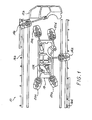
- Figure 2 is a simplified perspective view of the workstation according to the present invention with a first material handling robot at a loading position, a second material handling robot at a processing position, and material processing robots located adjacent the processing position in between the first and second processing paths followed by the first and second material handling robots; and
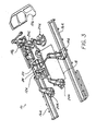
- Figure 3 is a simplified perspective view of the workstation according to the present invention with the first material handling robot moved into the processing position, the second material handling robot moved to the unloading position, and the material processing robot located adjacent the processing position in between the first and second processing paths.
- Referring now to Figures1-3, the present invention includes a
flexible body workstation 10 for assembling workpieces 12. Theworkstation 10 can include at least onematerial handling robot material handling robot stationary monument 18 can be provided if desired, for large workpieces to be processed. - By way of example and not limitation, at least one material handling robot can include a first
material handling robot 14a movable along a first processing path 16a for supporting afirst workpiece 12a to be moved along the first processing path 16a, and a secondmaterial handling robot 14b movable along a second processing path 16b for supporting a second workpiece 12b to be moved along the second processing path 16b. At least onestationary monument 18 can be provided, if desired for large workpieces, and can include a first stationary monument defining the processing position located between the first and second processing paths 16a, 16b. The at least one material handling robot 16a, 16b can be supported for movement along at least one overhead rail location and/or at least one floor supported rail location. - At least one
material processing robot processing workpieces 12a, 12b to be processed after being delivered by the at least onematerial handling robot material handling robot interchangeable end effecter 22 connectible to thematerial handling robot workpieces 12a, 12b. Theinterchangeable end effecter 22 can be provided for holding, supporting, locating and/or geometry fixturing thecorresponding workpiece 12a, 12b to be processed with the correspondingmaterial handling robot processing position 18. Theinterchangeable end effecter 22 can be floor mountable by the correspondingmaterial handling robot geometry fixture tool 24 for accurately positioning theworkpiece 12a, 12b to be processed with respect to theend effecter 22 thereby allowing the correspondingmaterial handling robot workpiece 12a, 12b andend effecter 22 in combination at the processing position in a predetermined location so that thematerial processing robots material processing robots processing workpieces 12a, 12b of different configurations or body styles of automobiles to be assembled along the assembly line. Thematerial processing robot - The present invention can include a method for processing a plurality of
workpieces 12a, 12b. The method can include the steps of supporting aworkpiece 12a, 12b to be moved along a processing path 16a, 16b with at least onematerial handling robot workpieces 12a, 12b to be processed that are delivered by the at least onematerial handling robot stationary monument 18 can be provided, if desired, for example to support a large workpiece for processing. - By way of example and not limitation, the method according to the present invention can include the step of supporting a first workpiece movable along the first processing path 16a with a first
material handling robot 14a, and supporting a second workpiece 12b to be moved along a second processing path 16b with a secondmaterial handling robot 14b movable along the second processing path 16b. Thefirst workpiece 12a or second workpiece 12b can be supported for processing after being delivered by one of either the first and secondmaterial handling robots second workpieces 12a, 12b to be processed after being delivered by one of either the first and secondmaterial handling robots material processing robot material processing robot - The method according to the present invention can include the step of holding and supporting different configurations of
workpieces 12a, 12b withinterchangeable end effecters 22 connectible to the first and secondmaterial handling robots interchangeable end effecters 22 and the correspondingmaterial handling robots interchangeable end effecters 22 with respect to the processing position with the correspondingmaterial handling robot end effecter 22 at the processing position, allowing the corresponding material handling robot to engage a processing tool, by way of example and not limitation, such as a weld gun, for performing additional processing operations on the workpiece to be processed located at the processing position. The method according to the present invention can include the step of accurately positioning theworkpieces 12a, 12b to be processed with a respect to theend effecter 22 with ageometry fixture tool 24 incorporated into theinterchangeable end effecter 22. The combination of theworkpiece 12a, 12b held with thegeometry fixture tool 24 incorporated into theinterchangeable end effecter 22 can be accurately positioned at the processing position with the correspondingmaterial handling robot material processing robots - When
material handling robot 14a is in the processing position, thematerial processing robots material handling robot 14a can disengage theend effecter 22 and pick up a processing tool for additional processing on the workpiece at the processing position. Simultaneously, the secondmaterial handling robot 14b can unload the carried workpiece at the unload or transfer position located at one end of the processing path 16b and return to the opposite end of the processing path 16b to a load or transfer position in order to carry a new unprocessed part to the processing position. An operator, or other automated equipment, can load the end effecter. The secondmaterial handling robot 14b can have exchanged end effecters, if necessary, in order to process a different configuration part from the workpiece previously carried along the second processing path 16b. After being loaded, the secondmaterial handling robot 14b goes to pounce and is ready to position parts for processing after the firstmaterial handling robot 14a is complete and clear from the processing position.Material handling robots material processing robots material processing robots material handling robots - The method of operation according to the present invention can include the following sequence. The
material handling robot 14a can retrieve an end effecter tool for the particular model or configuration of workpiece to be processed or welded. Thematerial handling robot 14a can move to the load position and can present the retrieved end effecter to an operator or other automated equipment for loading. Thematerial handling robot 14a can move to a processing position or weld position, locating the retrieved end effecter tool with respect to a station with precise positioning for processing or welding. If required, thematerial handling robot 14a can disengage from the end effecter and pick up a processing tool such as a weld gun for additional processing to be performed on the workpiece, such as welding. Thematerial handling robot 14a after the processing is complete can move to an unload station and can present the workpiece to an operator or other automated equipment, such as a downstream robot at the next workstation to unload. Storage bins can be provided for various configurations of end effecters for processing various configurations of workpieces along the processing paths. Whilematerial handling robot 14a is located at the processing position,material handling robot 14b can unload a completed processed workpiece, such as a complete welded part, can change end effecter for the next workpiece to be processed or part to be welded, and can be moved to the load station to present the retrieved end effecter to an operator or other automated equipment for loading. Thematerial handling robot 14b then goes to pounce at the processing position after thematerial handling robot 14a is completely clear of the processing position. - While the invention has been described in connection with what is presently considered to be the most practical and preferred embodiment, it is to be understood that the invention is not to be limited to the disclosed embodiments but, on the contrary, is intended to cover various modifications and equivalent arrangements included within the spirit and scope of the appended claims, which scope is to be accorded the broadest interpretation so as to encompass all such modifications and equivalent structures as is permitted under the law.
Claims (20)
- A workstation for processing a plurality of workpieces comprising:at least one material handling robot movable along a processing path for supporting a workpiece to be moved along the processing path; andat least one station defined by at least one processing position adjacent the processing path for receiving workpieces to be processed when delivered and positioned by the at least one material handling robot.
- The workstation of claim 1, wherein the at least one material handling robot further comprises:a first material handling robot movable along a first processing path for supporting a first workpiece to be moved along the first processing path; anda second material handling robot movable along a second processing path for supporting a second workpiece to be moved along the second processing path.
- The workstation of claim 2, wherein the at least one station further comprises:a first station monument defining the processing position located between the first and second processing paths for supporting a workpiece to be processed delivered by one of either the first and second material handling robot.
- The workstation of claim 1 further comprising:at least one material processing robot located adjacent the processing position for processing workpieces to be processed after being delivered by the first material handling robot.
- The workstation of claim 1 further comprising:interchangeable end effecters connectible to the first material handling robot for holding and supporting different workpiece configurations.
- The workstation of claim 5 further comprising:the interchangeable end effecters for locating the workpieces to be processed with the corresponding material handling robot at the processing position.
- The workstation of claim 5 further comprising:the corresponding material handling robot disengageable from the end effecter at the processing position, allowing engagement with a material processing tool for performing additional processing operations on the workpiece to be processed located at the processing position.
- The workstation of claim 5 further comprising:the interchangeable end effecters being floor mountable by the corresponding material handling robot at the processing position.
- The workstation of claim 5 further comprising:a geometry fixture tool incorporated into the interchangeable end effecters for accurately positioning the workpieces to be processed with respect to the end effecter and allowing the corresponding material handling robot to accurately position the workpiece and end effecter combination at the processing position.
- A method for processing a plurality of workpieces comprising the steps of:supporting a workpiece to be moved along a processing path with at least one material handling robot movable along the processing path; andreceiving workpieces to be processed when delivered and positioned by the at least one material handling robot with respect to at least one station defined by at least one processing position adjacent the processing path.
- The method of claim 10 further comprising the step of:supporting a first workpiece to be moved along a first processing path with a first material handling robot; andsupporting a second workpiece to be moved along a second processing path with a second material handling robot movable along the second processing path.
- The method of claim 11 further comprising the step of:supporting a workpiece to be processed delivered by one of either the first and second material handling robots with at least one station monument located between the first and second processing paths.
- The method of claim 11 further comprising the step of:processing workpieces to be processed after being delivered by one of either the first and second material handling robots with at least one material processing robot located adjacent the processing position.
- The method of claim 11 further comprising the step of:holding and supporting different workpiece configurations with interchangeable end effecters connectible to the first and second material handling robots.
- The method of claim 14 further comprising the step of:locating different workpiece configurations with the interchangeable end effecters and the corresponding material handling robots at the processing position.
- The method of claim 14 further comprising the step of:mounting one of the interchangeable end effecters with respect to the at least one station defined by the at least one processing position with the corresponding material handling robot.
- The method of claim 14 further comprising the step of:disengaging the corresponding material handling robot from the end effecter at the processing position.
- The method of claim 17 further comprising the step of:engaging the corresponding material handling robot with a material processing tool for performing additional processing on the workpiece to be processed located at the processing position.
- The method of claim 14 further comprising the step of:accurately positioning the workpieces to be processed with respect to the end effecter with a geometry fixture tool incorporated into the interchangeable end effecters.
- The method of claim 19 further comprising the step of:accurately positioning the workpiece and end effecter combination at the processing position with the corresponding material handling robot.
Applications Claiming Priority (6)
| Application Number | Priority Date | Filing Date | Title |
|---|---|---|---|
| US54812904P | 2004-02-26 | 2004-02-26 | |
| US548129P | 2004-02-26 | ||
| US61842204P | 2004-10-13 | 2004-10-13 | |
| US618422P | 2004-10-13 | ||
| US52487 | 2005-02-04 | ||
| US11/052,487 US20050189399A1 (en) | 2004-02-26 | 2005-02-04 | Flexible body workstation for assembling workpieces |
Publications (2)
| Publication Number | Publication Date |
|---|---|
| EP1568582A2 true EP1568582A2 (en) | 2005-08-31 |
| EP1568582A3 EP1568582A3 (en) | 2006-01-18 |
Family
ID=34753576
Family Applications (1)
| Application Number | Title | Priority Date | Filing Date |
|---|---|---|---|
| EP05003974A Withdrawn EP1568582A3 (en) | 2004-02-26 | 2005-02-24 | Workstation for assembling workpieces in an automotive assembly line |
Country Status (3)
| Country | Link |
|---|---|
| US (1) | US20050189399A1 (en) |
| EP (1) | EP1568582A3 (en) |
| CA (1) | CA2498168A1 (en) |
Cited By (6)
| Publication number | Priority date | Publication date | Assignee | Title |
|---|---|---|---|---|
| GB2447455A (en) * | 2007-03-12 | 2008-09-17 | Master Automation Group Oy | A support arrangement for a treatment device |
| WO2013167184A1 (en) * | 2012-05-09 | 2013-11-14 | Abb Technology Ag | Adaptable facility for assembling different sheet metal elements |
| DE202014101002U1 (en) | 2014-03-06 | 2015-06-12 | Kuka Systems Gmbh | manufacturing station |
| CN111266762A (en) * | 2018-12-05 | 2020-06-12 | 广州中国科学院先进技术研究所 | Multi-robot-based cooperative welding method and system |
| US10696339B2 (en) | 2014-03-06 | 2020-06-30 | Kuka Systems Gmbh | Manufacturing station, manufacturing plant and method |
| CN113275799A (en) * | 2021-06-01 | 2021-08-20 | 东风柳州汽车有限公司 | Welding system for vehicle assembly |
Families Citing this family (10)
| Publication number | Priority date | Publication date | Assignee | Title |
|---|---|---|---|---|
| US8201723B2 (en) * | 2008-03-12 | 2012-06-19 | Comau, Inc. | Robotic high density welding body shop |
| US8713780B2 (en) | 2008-05-13 | 2014-05-06 | Comau, Inc. | High density welding subassembly machine |
| JP6068980B2 (en) * | 2009-12-21 | 2017-01-25 | ピレリ・タイヤ・ソチエタ・ペル・アツィオーニ | Process and plant for building tires |
| WO2014148032A1 (en) * | 2013-03-19 | 2014-09-25 | パナソニック株式会社 | Robot system control method and robot system |
| EP3233370B1 (en) | 2014-12-15 | 2018-09-12 | Comau LLC | Modular vehicle assembly system and method |
| US10384873B2 (en) | 2016-05-06 | 2019-08-20 | Comau Llc | Inverted carrier lift device system and method |
| US10640297B2 (en) | 2017-11-07 | 2020-05-05 | Comau Llc | Transport system and methods |
| DE102018122499A1 (en) * | 2018-09-14 | 2020-03-19 | HELLA GmbH & Co. KGaA | Device with a first and a second robot and method for their operation |
| US11420853B2 (en) | 2019-10-03 | 2022-08-23 | Comau Llc | Assembly material logistics system and methods |
| MX2022014615A (en) | 2020-06-08 | 2023-01-04 | Comau Llc | Assembly material logistics system and methods. |
Family Cites Families (29)
| Publication number | Priority date | Publication date | Assignee | Title |
|---|---|---|---|---|
| US4402053A (en) * | 1980-09-25 | 1983-08-30 | Board Of Regents For Education For The State Of Rhode Island | Estimating workpiece pose using the feature points method |
| US4488241A (en) * | 1981-12-08 | 1984-12-11 | Zymark Corporation | Robot system with interchangeable hands |
| US4676541A (en) * | 1982-11-27 | 1987-06-30 | Cleveland-Guest (Engineering) Limited | Robot hand |
| US4530456A (en) * | 1983-05-04 | 1985-07-23 | Ppg Industries, Inc. | Method and apparatus for soldering by means of an industrial robot |
| CA1234482A (en) * | 1984-12-19 | 1988-03-29 | Daifuku Co., Ltd. | Method and apparatus for mounting automobile parts to both sides of a body |
| US4852242A (en) * | 1988-03-24 | 1989-08-01 | Hewlett-Packard Company | Tool coupling apparatus and method |
| US4883939A (en) * | 1988-06-21 | 1989-11-28 | Automatic Tool Control And Management Systems, Inc. | Automatic tool changer for workpiece processing machines |
| US5211528A (en) * | 1989-08-31 | 1993-05-18 | Mitsubishi Denki Kabushiki Kaisha | Industrial robot apparatus |
| JP2895906B2 (en) * | 1990-03-31 | 1999-05-31 | マツダ株式会社 | Auto body assembly equipment |
| US5111988A (en) * | 1990-04-16 | 1992-05-12 | Saturn Corporation | Flexible automated body assembly system and method |
| IT1248419B (en) * | 1990-06-15 | 1995-01-16 | Comau Spa | ASSEMBLY STATION OF A PRINTED SHEET STRUCTURE PROVIDED WITH A WELDING ROBOT THAT CAN ALSO BE USED FOR THE PERIODIC CONTROL OF THE EQUIPMENT USED IN THE STATION. |
| US5409158A (en) * | 1993-07-08 | 1995-04-25 | Progressive Tool & Industries Company | Automobile framing system |
| DE19713860A1 (en) * | 1997-04-04 | 1998-10-08 | Kuka Schweissanlagen Gmbh | Method and device for manufacturing complex workpieces |
| EP0933161B1 (en) * | 1998-02-03 | 2001-04-04 | COMAU S.p.A. | Device for assembling motor-vehicle bodies by spot-welding |
| JP4330703B2 (en) * | 1999-06-18 | 2009-09-16 | 東京エレクトロン株式会社 | Transport module and cluster system |
| CA2281175C (en) * | 1999-08-27 | 2006-03-14 | Joe E. Taylor | Sunroof opening for vehicle roof panel |
| US6129031A (en) * | 1999-11-16 | 2000-10-10 | The Boeing Company | Robotic stitching apparatus and end effector therefor |
| CA2323114C (en) * | 1999-11-18 | 2007-12-11 | Honda Giken Kogyo Kabushiki Kaisha | Apparatus for assembling floor of vehicle |
| JP2001250854A (en) * | 1999-12-28 | 2001-09-14 | Nikon Corp | Carrying method and device, positioning method and device, substrate retaining method and device, exposure method and projection aligner, device and manufacturing method thereof |
| SE0002097D0 (en) * | 2000-06-05 | 2000-06-05 | Abb Ab | Procedure and plant for assembly |
| US6662083B2 (en) * | 2000-10-31 | 2003-12-09 | Progressive Tool & Industries Co. | Multiple robotic workstation with multiple fixtures |
| US6609869B2 (en) * | 2001-01-04 | 2003-08-26 | Asm America | Transfer chamber with integral loadlock and staging station |
| US6674022B2 (en) * | 2001-03-23 | 2004-01-06 | Ortho-Mcneil Pharmaceutical, Inc. | Apparatus and method for transferring and weighing powder materials using pipette transfer devices |
| US6627016B2 (en) * | 2001-10-25 | 2003-09-30 | Abb, Inc. (Flexible Automation Division) | Robotic assembly process for plastic components |
| US6899377B2 (en) * | 2002-09-24 | 2005-05-31 | Ford Motor Company | Vehicle body |
| US7178227B2 (en) * | 2002-09-24 | 2007-02-20 | Ford Motor Company | Workpiece presenter for a flexible manufacturing system |
| DE20304022U1 (en) * | 2003-03-12 | 2004-07-22 | Kuka Schweissanlagen Gmbh | Manufacturing plant for components, in particular body components |
| JP4310626B2 (en) * | 2003-07-29 | 2009-08-12 | アイシン・エィ・ダブリュ株式会社 | Machining line |
| JP2006187826A (en) * | 2005-01-05 | 2006-07-20 | Kawasaki Heavy Ind Ltd | Robot controller |
-
2005
- 2005-02-04 US US11/052,487 patent/US20050189399A1/en not_active Abandoned
- 2005-02-24 CA CA002498168A patent/CA2498168A1/en not_active Abandoned
- 2005-02-24 EP EP05003974A patent/EP1568582A3/en not_active Withdrawn
Non-Patent Citations (1)
| Title |
|---|
| None |
Cited By (7)
| Publication number | Priority date | Publication date | Assignee | Title |
|---|---|---|---|---|
| GB2447455A (en) * | 2007-03-12 | 2008-09-17 | Master Automation Group Oy | A support arrangement for a treatment device |
| WO2013167184A1 (en) * | 2012-05-09 | 2013-11-14 | Abb Technology Ag | Adaptable facility for assembling different sheet metal elements |
| DE202014101002U1 (en) | 2014-03-06 | 2015-06-12 | Kuka Systems Gmbh | manufacturing station |
| US10696339B2 (en) | 2014-03-06 | 2020-06-30 | Kuka Systems Gmbh | Manufacturing station, manufacturing plant and method |
| CN111266762A (en) * | 2018-12-05 | 2020-06-12 | 广州中国科学院先进技术研究所 | Multi-robot-based cooperative welding method and system |
| CN111266762B (en) * | 2018-12-05 | 2022-07-05 | 广州中国科学院先进技术研究所 | Multi-robot-based cooperative welding method and system |
| CN113275799A (en) * | 2021-06-01 | 2021-08-20 | 东风柳州汽车有限公司 | Welding system for vehicle assembly |
Also Published As
| Publication number | Publication date |
|---|---|
| CA2498168A1 (en) | 2005-08-26 |
| EP1568582A3 (en) | 2006-01-18 |
| US20050189399A1 (en) | 2005-09-01 |
Similar Documents
| Publication | Publication Date | Title |
|---|---|---|
| EP1568582A2 (en) | Workstation for assembling workpieces in an automotive assembly line | |
| US6651867B2 (en) | Robotic turntable | |
| US6662083B2 (en) | Multiple robotic workstation with multiple fixtures | |
| US7650679B2 (en) | Method of handling a workpiece in a workstation | |
| US20040138782A1 (en) | Multi-station robotic welding assembly | |
| US5111988A (en) | Flexible automated body assembly system and method | |
| US20050044700A1 (en) | Manufacturing assembly line and a method of designing a manufacturing assembly line | |
| US7178227B2 (en) | Workpiece presenter for a flexible manufacturing system | |
| US20040056498A1 (en) | Vehicle body | |
| CN213857747U (en) | Automatic welding device | |
| US4960969A (en) | Method of processing and transferring vehicle body members with a robot | |
| CN111774746B (en) | Flexible production line for side wall welding | |
| JP2000177663A (en) | Method and device for assembling car body | |
| US6918577B2 (en) | Tooling plate for a flexible manufacturing system | |
| US8312611B2 (en) | Assembling method and apparatus for assembly, and assembling method and apparatus for workpiece | |
| US20050230374A1 (en) | Multi-architecture flexible assembly structure and method | |
| JPH06285687A (en) | Welding equipment for automotive body | |
| US20040055129A1 (en) | Method of engineering a flexible process line | |
| JP3308625B2 (en) | Welding line | |
| JPH10315090A (en) | Machining device and machining method | |
| JP2001151175A (en) | Assembling jig device for vehicle body | |
| US20040055147A1 (en) | Process line for a flexible manufacturing system | |
| CN216706438U (en) | Production line for vehicles | |
| CA2398557C (en) | Multiple robotic workstation with multiple fixtures | |
| JPH0225710B2 (en) |
Legal Events
| Date | Code | Title | Description |
|---|---|---|---|
| PUAI | Public reference made under article 153(3) epc to a published international application that has entered the european phase |
Free format text: ORIGINAL CODE: 0009012 |
|
| AK | Designated contracting states |
Kind code of ref document: A2 Designated state(s): AT BE BG CH CY CZ DE DK EE ES FI FR GB GR HU IE IS IT LI LT LU MC NL PL PT RO SE SI SK TR |
|
| AX | Request for extension of the european patent |
Extension state: AL BA HR LV MK YU |
|
| PUAL | Search report despatched |
Free format text: ORIGINAL CODE: 0009013 |
|
| AK | Designated contracting states |
Kind code of ref document: A3 Designated state(s): AT BE BG CH CY CZ DE DK EE ES FI FR GB GR HU IE IS IT LI LT LU MC NL PL PT RO SE SI SK TR |
|
| AX | Request for extension of the european patent |
Extension state: AL BA HR LV MK YU |
|
| RIC1 | Information provided on ipc code assigned before grant |
Ipc: B23K 37/047 20060101ALI20051128BHEP Ipc: B62D 65/02 20060101AFI20050427BHEP |
|
| AKX | Designation fees paid | ||
| REG | Reference to a national code |
Ref country code: DE Ref legal event code: 8566 |
|
| STAA | Information on the status of an ep patent application or granted ep patent |
Free format text: STATUS: THE APPLICATION IS DEEMED TO BE WITHDRAWN |
|
| 18D | Application deemed to be withdrawn |
Effective date: 20060719 |