EP1568567A1 - Lenksäulenbaueinheit und Verfahren zu ihrer Herstellung - Google Patents
Lenksäulenbaueinheit und Verfahren zu ihrer Herstellung Download PDFInfo
- Publication number
- EP1568567A1 EP1568567A1 EP05075402A EP05075402A EP1568567A1 EP 1568567 A1 EP1568567 A1 EP 1568567A1 EP 05075402 A EP05075402 A EP 05075402A EP 05075402 A EP05075402 A EP 05075402A EP 1568567 A1 EP1568567 A1 EP 1568567A1
- Authority
- EP
- European Patent Office
- Prior art keywords
- support bracket
- steering column
- column assembly
- upper support
- set forth
- Prior art date
- Legal status (The legal status is an assumption and is not a legal conclusion. Google has not performed a legal analysis and makes no representation as to the accuracy of the status listed.)
- Granted
Links
- 238000004519 manufacturing process Methods 0.000 title description 3
- 238000000034 method Methods 0.000 claims abstract description 14
- 230000002093 peripheral effect Effects 0.000 claims description 6
- 238000002347 injection Methods 0.000 claims description 5
- 239000007924 injection Substances 0.000 claims description 5
- 238000004806 packaging method and process Methods 0.000 abstract description 4
- 238000012360 testing method Methods 0.000 description 8
- 229910000831 Steel Inorganic materials 0.000 description 3
- XAGFODPZIPBFFR-UHFFFAOYSA-N aluminium Chemical compound [Al] XAGFODPZIPBFFR-UHFFFAOYSA-N 0.000 description 3
- 229910052782 aluminium Inorganic materials 0.000 description 3
- 230000000712 assembly Effects 0.000 description 3
- 238000000429 assembly Methods 0.000 description 3
- 239000007769 metal material Substances 0.000 description 3
- 239000002861 polymer material Substances 0.000 description 3
- 239000010959 steel Substances 0.000 description 3
- 230000007246 mechanism Effects 0.000 description 2
- 238000000926 separation method Methods 0.000 description 2
- 238000004364 calculation method Methods 0.000 description 1
- 230000000295 complement effect Effects 0.000 description 1
- 230000003247 decreasing effect Effects 0.000 description 1
- 230000003292 diminished effect Effects 0.000 description 1
- 238000009434 installation Methods 0.000 description 1
- 239000000463 material Substances 0.000 description 1
- 238000013178 mathematical model Methods 0.000 description 1
- 238000012986 modification Methods 0.000 description 1
- 230000004048 modification Effects 0.000 description 1
Images



Classifications
-
- B—PERFORMING OPERATIONS; TRANSPORTING
- B62—LAND VEHICLES FOR TRAVELLING OTHERWISE THAN ON RAILS
- B62D—MOTOR VEHICLES; TRAILERS
- B62D1/00—Steering controls, i.e. means for initiating a change of direction of the vehicle
- B62D1/02—Steering controls, i.e. means for initiating a change of direction of the vehicle vehicle-mounted
- B62D1/16—Steering columns
-
- B—PERFORMING OPERATIONS; TRANSPORTING
- B62—LAND VEHICLES FOR TRAVELLING OTHERWISE THAN ON RAILS
- B62D—MOTOR VEHICLES; TRAILERS
- B62D1/00—Steering controls, i.e. means for initiating a change of direction of the vehicle
- B62D1/02—Steering controls, i.e. means for initiating a change of direction of the vehicle vehicle-mounted
- B62D1/16—Steering columns
- B62D1/18—Steering columns yieldable or adjustable, e.g. tiltable
- B62D1/19—Steering columns yieldable or adjustable, e.g. tiltable incorporating energy-absorbing arrangements, e.g. by being yieldable or collapsible
- B62D1/195—Yieldable supports for the steering column
Definitions
- the subject invention relates to a vehicle steering column, and more particularly to a collapsible steering column.
- a steering column assembly of the present invention includes a lower support bracket and an upper support bracket.
- the steering column assembly includes a yoke support housing and a plurality of tubes spaced from one another circumferentially about a longitudinal axis and rigidly interconnecting the yoke support housing and the upper support bracket.
- a jacket is fixed to one of the lower and upper support brackets and is slidable relative to the other of the lower and upper support brackets about the longitudinal axis between an uncollapsed position and a collapsed position of said steering column assembly.
- the present invention includes a method of fabricating the steering column assembly having the lower support bracket and the upper support bracket presenting a longitudinal axis disposed within and extending through the lower support bracket and the upper support bracket.
- the method includes the steps of positioning the yoke support housing adjacent to the upper support bracket, selecting a group of tubes from a plurality of tube configurations, and mechanically interconnecting the yoke support housing with the upper support bracket by disposing the group of tubes therebetween and by spacing the tubes from one another circumferentially about the longitudinal axis.
- the method includes the step of disposing the jacket fixed to one of the lower and upper support bracket to facilitate slidably movement of the jacket relative to the other of the lower and the upper support brackets about the longitudinal axis between an uncollapsed position and a collapsed position of the steering column assembly.
- An advantage of the present invention is to provide the steering column assembly design that achieves a high section modulus, and improved and predetermined stiffness characteristics.
- Another advantage of the present design is to provide the steering column assembly having improved packaging characteristics to hold various components of a tilt assembly.
- Still another advantage of the present invention is to provide the steering column assembly having the yoke support housing interconnected with the upper support bracket and the jacket fixed between the upper and lower support brackets.
- This design facilitates easier and more reliable movement of the jacket relative to one of the lower and the upper support brackets about the longitudinal axis between the uncollapsed and collapsed position of the steering column assembly thereby eliminating need to translate tubes of prior art design through the corresponding holes defined in the prior art upper and lower brackets for spanning the entire prior art steering column.
- Still another advantage of the present invention is to provide tubes interconnecting the upper support bracket and the yoke support housing to store wires and other devices within the tubes, thereby providing the tubes with wire routing and wire protecting features at no additional cost.
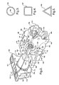
- a steering column assembly of the present invention is generally shown at 100.
- the steering column assembly 100 of the present invention includes a lower support bracket 102, an upper support bracket 104, and a jacket 106 disposed within and extending along a longitudinal axis O through the lower support bracket 102 and the upper support bracket 104.
- the steering column assembly 100 includes a yoke support housing 108 and a plurality of tubes 110 spaced from one another circumferentially about the longitudinal axis O of the jacket 106 and interconnecting the yoke support housing 108 and the upper support bracket 104.
- the lower support bracket 102 of the present invention includes a generally rectangular configuration and is designed for connecting the steering column assembly 100 to a body of a vehicle (not shown).
- the lower support bracket 102 has top 111, bottom 112, side walls 114, 116, and front 118 and rear 120 ends.
- the lower support bracket 102 includes an opening 122 defined therewithin.
- the lower support bracket 102 is preferably injection molded from a plastic or polymer material, however it should be recognized that it can also be molded or machined from a metallic material such as steel or aluminum.
- the upper support bracket 104 has a generally rectangular configuration and is designed for connecting the steering column assembly 100 to the body of the vehicle adjacent from the point of connection of the lower support bracket 102.
- the upper support bracket 104 includes top side 124, bottom side 126, side walls 128, 130 interconnected therebetween at the respective tops to define a peripheral edge, generally indicated at 132.
- the upper support bracket 104 further includes rear 134 and front 136 ends and a boss section 138 integral with the upper support bracket 104 and extending from the rear end 134 to the front end 136.
- the boss section 138 includes an inlet of a generally circular configuration, generally indicated at 140, defined therewithin to receive the jacket 106 stationary engaged within the inlet 140.
- the upper support bracket 104 includes interior pockets 142 spaced one from the other and defined around the peripheral edge 132 at the front end 136 of the upper support bracket 104.
- the interior pockets 142 are interconnected with the boss section 138 by a wall 144, respectively, to increase stiffness of the upper support bracket 104.
- the upper support bracket 104 includes a flange 146 integral with and extending outwardly from each of the side walls 128, 130 in a cantelivered fashion.
- Each flange 146 includes a slot 148 defined therewithin to receive a shear device (not shown) activated during a collision of a vehicle.
- the upper support bracket 104 is preferably injection molded from a plastic or polymer material, however it should be recognized that it can also be molded or machined from a metallic material such as steel or aluminum.
- the jacket 106 of the steering column assembly 100 includes a generally tubular configuration and has the terminal ends 150, 152.
- the jacket 106 includes a first sleeve 154, as best shown in Figure 1, disposed annularly about one of the terminal ends 150 of the jacket 106 and between the lower support bracket 102.
- the first sleeve 154 prevents frictional engagement between the jacket 106 sliding through the lower support bracket 102 in case of a collision.
- the jacket 106 includes a second sleeve (not shown), similar disposed annularly about another telescoping end 152 of the jacket 106 and between the upper support bracket 104.
- the second sleeve prevents frictional engagement between the jacket 106 sliding through the upper support bracket 104 in case of the collision.
- the lower support bracket 102 and the upper support bracket 104 are stationary mounted to the body of the vehicle. During the collision, the upper 104 and lower 102 support brackets collapse internally with respect to one another.
- Figure 7 shows the steering column assembly 100 in an internally collapsing mode, wherein the jacket 106 is connected to the lower support bracket 102 and extends through and beyond the upper support bracket 104 still maintaining stiffness between the upper support bracket 104 and the yoke support housing 108.
- the steering column assembly 100 is shown in a translating mode, wherein the jacket 106 is connected to the upper support bracket 104 and extends through and beyond the lower support bracket 102 still maintaining stiffness between the upper support bracket 104 and the yoke support housing 108.
- the jacket 106 and the sleeves 156 are preferably injection molded from a plastic or polymer material, however it should be recognized that it can also be molded or machined from a metallic material such as steel or aluminum.
- the yoke support housing 108 is designed to mechanically engage a tilt assembly 158 therewithin.
- the yoke support housing 108 includes a generally rectangular configuration and has rear 160 and front 162 ends, top 164, bottom 166, and sides 168, 170 interconnected one with the other.
- the yoke support housing 108 includes a hole of a circular configuration, generally indicated at 172, defined therewithin and spaced longitudinally and axially with respect to the jacket 106.
- the yoke support housing 108 includes a projection 174 integral with and extending outwardly from each of the sides 168, 170 at the front end 162 of the yoke support housing 108 to engage the tilt assembly 158.
- the yoke support housing 108 includes exterior pockets 180 integral with the yoke support housing 108 at the top 164, bottom 166 and sides 168, 170.
- the exterior pockets 180 are spaced longitudinally and adjacent the interior pockets 142 of the upper support bracket 104.
- the invention includes four tubes 110 having a body defining inner 182 and outer 184 diameters, as view in cross section, and terminal ends 186, 188, respectively.
- the tubes 110 are spaced from one another circumferentially about the longitudinal axis O of the jacket 106 and interconnecting the yoke support housing 108 and the upper support bracket 104.
- the tubes 110 are mechanically connected with the internal pockets 142 of the upper support bracket 104 and exterior pockets 180 of the yoke support housing 108.
- the tubes 110 include an equal and predetermined thickness between the outer 184 and inner 182 diameters, wherein the outer diameter 184 is complimentary to predetermined inner diameter 143 of the interior pockets 142 and inner diameter 181 of the exterior pockets 180.
- the tubes 110 may include triangular and rectangular configurations, as viewed in cross section.
- the interior pockets 142 of the upper support bracket 104 and the exterior pockets 180 of the yoke support housing 108 of the alternative embodiment include triangular and rectangular configurations, (not shown) to mate with the respective tubes 110 defining triangular 185, rectangular 187 configurations, respectively, as shown in Figures 4 and 5.
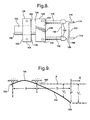
- the outer diameter 184 of the tube 110 is constant wherein the inner diameter 182 has a variable value with respect to different designs of the steering column assembly 100 to increase stiffness of the assembly 100 thereby increasing moment of Inertia.
- the steering column assembly 100 includes a shaft 189 extending through the yoke support housing 108, the jacket 106, the upper 104 and lower 102 support brackets of the steering column assembly 100.
- the increased distance between the outer 184 and inner 182 diameters of the tubes 110 provides for better stiffness of the assembly 100.
- An impact of the tube thickness to the moment of Inertia is shown in the formula: where, Ix is a moment of Inertia distributed along axis x , extending horizontally from the longitudinal axis, Iy is a moment of Inertia distributed along axis y , extending vertically from the longitudinal axis O, Do is the outer diameter 184 of the tube 110, Di is the inner diameter 182 of the tube 110, dx is a distance from the longitudinal axis O in the axis x direction, dy is a distance from the longitudinal axis O in the axis y direction, and ⁇ is a ration of a circumference of the tube 110 as view in cross section, divided into a diameter of the tube 110, wherein ⁇ has
- the length of the tube 110 with respect to each individual design of the steering column assembly 100 provides for increased stiffness of the steering column assembly 100, as shown in Figure 9.
- an impact of the tube 110 length to a deflection V is shown in the formula: P ( b + x ) 2 ( a + b + x ) 3 EI ⁇ Pb 2 L 3 EI ⁇ P ( b - x ) 2 ( a + b - x ) 3 EI
- I is a moment of Inertia
- P is a mass of a load provided by the yoke support housing 108
- L is the length of the tube 110
- E is a modulus of elasticity of the tube 110
- a is a distance between the lower support bracket 102 and the upper support bracket 104 connected to the body of the vehicle
- b is a distance between the upper support bracket 104 and the yoke support housing 108
- x is a value of a increased distance of b
- the design of the present invention achieves a high section modulus, which has a proportional influence to the natural frequency of the steering column assembly 100 through the stiffness.
- the advantages of the present design include improved packaging characteristics, unlike typical column assembly designs, shown in aforementioned United States Patent No. 6,592,148 to Byers et al. and United States Patent Application Publication No. 2002/0121771 to Shifflett et al.
- a space defined between the upper support bracket 104 and the yoke support housing 108 interconnected and spaced apart by the tubes 110 define a gap, generally indicated at 190, to hold various components of the tilt assembly 158 including ECL mechanisms, steering tube position sensors, BSTI switches, and the like (not shown).
- the tubular geometry of the tubes 110 provides for ability to store wires 192 and other devices within the tubes 110, thereby providing the tubes 110 with wire routing and wire protecting features at no additional cost.
- the invention includes a method, generally indicated at 200, of fabricating the steering column assembly 100, as shown in Figure 10.
- the method 200 begins with positioning 202 the yoke support housing 108 adjacent the upper support bracket 104.
- the next step includes selecting the group of tubes 110 having the inner 182 and outer 184 diameters from a plurality of tube configurations.
- the next step of the method 200 includes connecting 204 the yoke support housing 108 to the upper support bracket 104, wherein the yoke support housing 108 is longitudinally spaced from the upper support bracket 104 by the group of four tubes 110 equally spaced from one another.
- the step of connecting 204 the yoke support housing 108 to the upper support bracket 104 further includes disposing the tubes 110 having an equal and predetermined thickness between the outer 184 and inner 182 diameters, as viewed in cross section.
- the tubes 110 are mechanically interconnected within the interior pockets 142 of the upper support bracket 104 at one of the terminal ends 186 and within the exterior pockets 180 of the yoke support housing 108 at another terminal end 188, respectively.
- various methods of interconnecting the tubes 110 within the upper support bracket 104 and the yoke support housing 108 are provided.
- the tubes 110 are being press stamped within the upper support bracket 104 and the yoke support housing 108.
- the tubes 110 may include male connectors (not shown) to complement with female connectors (not shown) defined within the interior pockets 142 of the upper support bracket 104 and exterior pockets 180 of the yoke support housing 108.
- the step of connecting 204 the yoke support housing 108 to the upper support bracket 104 of the method 200 further includes the step of disposing 206 a jacket 106 fixed to one of the lower 102 and upper 104 support bracket to facilitate slidably movement of the jacket 106 relative to the other of the lower 102 and the upper 104 support brackets about the longitudinal axis O between an uncollapsed position and a collapsed position of the steering column assembly 100.
- the jacket 106 requires the sleeve 154 to prevent frictional engagement between the jacket 106 and the upper and lower 102 support brackets.
- the method 200 includes the step of disposing (not shown) the sleeve 154 annularly about another terminal 152 end of the jacket 106 and between the upper support bracket 104.
- the method 200 includes the step of disposing the sleeve 154 annularly about one of the terminal ends 150 of the jacket 106 and between the lower support bracket 102 (not shown).
Landscapes
- Engineering & Computer Science (AREA)
- Chemical & Material Sciences (AREA)
- Combustion & Propulsion (AREA)
- Transportation (AREA)
- Mechanical Engineering (AREA)
- Steering Controls (AREA)
Applications Claiming Priority (2)
| Application Number | Priority Date | Filing Date | Title |
|---|---|---|---|
| US10/788,150 US7188866B2 (en) | 2004-02-26 | 2004-02-26 | Steering column assembly and method of fabricating the same |
| US788150 | 2004-02-26 |
Publications (2)
| Publication Number | Publication Date |
|---|---|
| EP1568567A1 true EP1568567A1 (de) | 2005-08-31 |
| EP1568567B1 EP1568567B1 (de) | 2007-05-16 |
Family
ID=34750526
Family Applications (1)
| Application Number | Title | Priority Date | Filing Date |
|---|---|---|---|
| EP05075402A Expired - Lifetime EP1568567B1 (de) | 2004-02-26 | 2005-02-18 | Lenksäulenbaueinheit und Verfahren zu ihrer Herstellung |
Country Status (4)
| Country | Link |
|---|---|
| US (1) | US7188866B2 (de) |
| EP (1) | EP1568567B1 (de) |
| AT (1) | ATE362441T1 (de) |
| DE (1) | DE602005001119T2 (de) |
Cited By (1)
| Publication number | Priority date | Publication date | Assignee | Title |
|---|---|---|---|---|
| EP1566323A3 (de) * | 2004-01-29 | 2007-07-18 | Delphi Technologies, Inc. | Lenksäulenmodul mit linearer Bewegungsbahn |
Families Citing this family (12)
| Publication number | Priority date | Publication date | Assignee | Title |
|---|---|---|---|---|
| JP4373950B2 (ja) * | 2005-03-31 | 2009-11-25 | 株式会社山田製作所 | ステアリングハンドルの位置調整装置 |
| EP1724183A3 (de) * | 2005-05-19 | 2011-06-22 | GM Global Technology Operations, Inc. | Lenksäule mit Schwingungsdämpfer |
| US20080211217A1 (en) * | 2007-03-02 | 2008-09-04 | Textron Inc. | Adjustable Steering System |
| KR100992695B1 (ko) * | 2007-11-13 | 2010-11-05 | 기아자동차주식회사 | 틸팅 및 텔레스코픽 스티어링컬럼의 록킹장치 구조 |
| FR2990180B1 (fr) * | 2012-05-04 | 2016-01-01 | Faurecia Interieur Ind | Ensemble d'aspect pour vehicule permettant de masquer un espace technique |
| US8777264B2 (en) * | 2012-10-05 | 2014-07-15 | GM Global Technology Operations LLC | Steering column assembly for a motor vehicle |
| FR3004154B1 (fr) * | 2013-04-04 | 2015-04-17 | Peugeot Citroen Automobiles Sa | Procede de fabrication d'un corps de colonne de direction de vehicule, et corps de colonne de direction de vehicule obtenu par un tel procede |
| US9649932B2 (en) | 2014-01-23 | 2017-05-16 | Steering Solutions Ip Holding Corporation | Rake lever actuated shift mechanism clamp |
| US9969260B2 (en) * | 2014-01-23 | 2018-05-15 | Steering Solutions Ip Holding Corporation | Steering column mounted telescoping transmission shifter |
| US9937790B2 (en) | 2015-02-19 | 2018-04-10 | Steering Solutions Ip Holding Corporation | Mounting assembly for vehicle shift mechanism |
| DE102015106030B4 (de) * | 2015-04-20 | 2022-12-15 | Zf Automotive Germany Gmbh | Lenksäulenbaueinheit sowie Verfahren zur Herstellung eines Halteelements für eine Lenksäulenbaueinheit |
| US11932305B2 (en) | 2022-03-01 | 2024-03-19 | Caterpillar Inc. | Steering bracket for construction machine |
Citations (2)
| Publication number | Priority date | Publication date | Assignee | Title |
|---|---|---|---|---|
| US20020121771A1 (en) * | 2001-03-02 | 2002-09-05 | David Shifflett | Breakaway steering column support for a vehicle |
| US6592148B2 (en) * | 2001-07-03 | 2003-07-15 | Delphi Technologies, Inc. | Steering column lower bracket |
Family Cites Families (12)
| Publication number | Priority date | Publication date | Assignee | Title |
|---|---|---|---|---|
| DE3838594A1 (de) * | 1988-11-15 | 1990-05-17 | Kolbenschmidt Ag | Einbauteil zur absorption von energie |
| US5117707A (en) | 1990-02-23 | 1992-06-02 | Fuji Kiko Company, Limited | Tilting steering column |
| US5081879A (en) | 1990-05-24 | 1992-01-21 | Ford Motor Company | Steering column assembly mounting bracket |
| IT1240960B (it) | 1990-06-26 | 1993-12-27 | Fiat Auto Spa | Sistema di supporto collassabile ad assorbimento di energia per un piantone sterzo di un veicolo. |
| JP3186456B2 (ja) | 1994-09-09 | 2001-07-11 | 日本精工株式会社 | ステアリング装置用自在継手のヨーク |
| EP0769445B1 (de) | 1995-10-17 | 1999-01-20 | General Motors Corporation | Energie-absorbierende Lenksäule für ein Kraftfahrzeug |
| DE19812172C1 (de) | 1998-03-19 | 1999-07-22 | Daimler Chrysler Ag | Lenksäulenanordnung für ein Kraftfahrzeug |
| US6435555B1 (en) | 2000-02-10 | 2002-08-20 | Delphi Technologies, Inc. | Collapsible steering column and method |
| US6685224B2 (en) * | 2001-12-27 | 2004-02-03 | Daimlerchrysler Corporation | Tilt steering column |
| US7048306B2 (en) * | 2002-09-05 | 2006-05-23 | Delphi Technologies, Inc. | Steering column with tubular structure |
| US7185918B2 (en) * | 2003-01-31 | 2007-03-06 | Delphi Technologies, Inc. | Linear tracking column module with pedal assembly |
| US7063354B2 (en) * | 2003-01-31 | 2006-06-20 | Delphi Technologies, Inc. | Linear tracking column module |
-
2004
- 2004-02-26 US US10/788,150 patent/US7188866B2/en not_active Expired - Fee Related
-
2005
- 2005-02-18 EP EP05075402A patent/EP1568567B1/de not_active Expired - Lifetime
- 2005-02-18 AT AT05075402T patent/ATE362441T1/de not_active IP Right Cessation
- 2005-02-18 DE DE602005001119T patent/DE602005001119T2/de not_active Expired - Lifetime
Patent Citations (2)
| Publication number | Priority date | Publication date | Assignee | Title |
|---|---|---|---|---|
| US20020121771A1 (en) * | 2001-03-02 | 2002-09-05 | David Shifflett | Breakaway steering column support for a vehicle |
| US6592148B2 (en) * | 2001-07-03 | 2003-07-15 | Delphi Technologies, Inc. | Steering column lower bracket |
Cited By (1)
| Publication number | Priority date | Publication date | Assignee | Title |
|---|---|---|---|---|
| EP1566323A3 (de) * | 2004-01-29 | 2007-07-18 | Delphi Technologies, Inc. | Lenksäulenmodul mit linearer Bewegungsbahn |
Also Published As
| Publication number | Publication date |
|---|---|
| US20050189756A1 (en) | 2005-09-01 |
| ATE362441T1 (de) | 2007-06-15 |
| DE602005001119D1 (de) | 2007-06-28 |
| US7188866B2 (en) | 2007-03-13 |
| EP1568567B1 (de) | 2007-05-16 |
| DE602005001119T2 (de) | 2007-09-13 |
Similar Documents
| Publication | Publication Date | Title |
|---|---|---|
| US7188866B2 (en) | Steering column assembly and method of fabricating the same | |
| JP7002787B2 (ja) | 振動数調整されたダンパ及び当該ダンパの製造で使用する方法 | |
| US3788148A (en) | Energy absorber for collapsible steering columns or the like | |
| US6729648B2 (en) | Non-linear energy absorbing column assembly | |
| JP5932854B2 (ja) | 燃料タンク | |
| US7497470B2 (en) | Energy absorbing apparatus | |
| EP2724025B1 (de) | Pleuelstangen-/kolbenanordnung für einen alternativen kompressor und montageverfahren für eine pleuelstangen-/kolbenanordnung für einen alternativen kompressor | |
| KR20190056903A (ko) | 자동차의 조향컬럼 | |
| EP0458456A1 (de) | Lagerungsmechanismus einer Lenksäule | |
| EP1728703B1 (de) | Adaptiv Energie aufnehmende Lenksäule | |
| US6508143B2 (en) | Structure for mounting to steering wheel | |
| KR101170259B1 (ko) | 자동차의 조향 컬럼 | |
| JP6191725B2 (ja) | 燃料タンク | |
| JP7174659B2 (ja) | 筒型防振装置用ブラケット | |
| JPH0529186Y2 (de) | ||
| JP2002264823A (ja) | 衝撃吸収式ステアリング装置 | |
| US8465051B2 (en) | Driver knee bolster of automobile | |
| US20070023227A1 (en) | Rack boot | |
| KR20190012401A (ko) | 차량용 조향 컬럼 | |
| JP7160806B2 (ja) | ステアリング装置 | |
| JP7211406B2 (ja) | 自動車用操舵装置の中間シャフト | |
| EP4230507A1 (de) | Verriegelungs-/entriegelungsvorrichtung für fahrzeugkotflügel und kotflügelanordnung | |
| JP6511338B2 (ja) | 空気ばね | |
| JP6068201B2 (ja) | クランプ及び部品支持システム | |
| JP6819253B2 (ja) | 中間シャフト |
Legal Events
| Date | Code | Title | Description |
|---|---|---|---|
| PUAI | Public reference made under article 153(3) epc to a published international application that has entered the european phase |
Free format text: ORIGINAL CODE: 0009012 |
|
| AK | Designated contracting states |
Kind code of ref document: A1 Designated state(s): AT BE BG CH CY CZ DE DK EE ES FI FR GB GR HU IE IS IT LI LT LU MC NL PL PT RO SE SI SK TR |
|
| AX | Request for extension of the european patent |
Extension state: AL BA HR LV MK YU |
|
| RIN1 | Information on inventor provided before grant (corrected) |
Inventor name: WAEGHE, AMELIA M. Inventor name: PONICHTERA, JEREMY A. Inventor name: RIDGWAY, JASON R. |
|
| 17P | Request for examination filed |
Effective date: 20060228 |
|
| AKX | Designation fees paid |
Designated state(s): AT BE BG CH CY CZ DE DK EE ES FI FR GB GR HU IE IS IT LI LT LU MC NL PL PT RO SE SI SK TR |
|
| GRAP | Despatch of communication of intention to grant a patent |
Free format text: ORIGINAL CODE: EPIDOSNIGR1 |
|
| GRAS | Grant fee paid |
Free format text: ORIGINAL CODE: EPIDOSNIGR3 |
|
| GRAA | (expected) grant |
Free format text: ORIGINAL CODE: 0009210 |
|
| AK | Designated contracting states |
Kind code of ref document: B1 Designated state(s): AT BE BG CH CY CZ DE DK EE ES FI FR GB GR HU IE IS IT LI LT LU MC NL PL PT RO SE SI SK TR |
|
| PG25 | Lapsed in a contracting state [announced via postgrant information from national office to epo] |
Ref country code: LI Free format text: LAPSE BECAUSE OF FAILURE TO SUBMIT A TRANSLATION OF THE DESCRIPTION OR TO PAY THE FEE WITHIN THE PRESCRIBED TIME-LIMIT Effective date: 20070516 Ref country code: FI Free format text: LAPSE BECAUSE OF FAILURE TO SUBMIT A TRANSLATION OF THE DESCRIPTION OR TO PAY THE FEE WITHIN THE PRESCRIBED TIME-LIMIT Effective date: 20070516 Ref country code: CH Free format text: LAPSE BECAUSE OF FAILURE TO SUBMIT A TRANSLATION OF THE DESCRIPTION OR TO PAY THE FEE WITHIN THE PRESCRIBED TIME-LIMIT Effective date: 20070516 |
|
| REG | Reference to a national code |
Ref country code: GB Ref legal event code: FG4D |
|
| REG | Reference to a national code |
Ref country code: CH Ref legal event code: EP |
|
| REG | Reference to a national code |
Ref country code: IE Ref legal event code: FG4D |
|
| REF | Corresponds to: |
Ref document number: 602005001119 Country of ref document: DE Date of ref document: 20070628 Kind code of ref document: P |
|
| PG25 | Lapsed in a contracting state [announced via postgrant information from national office to epo] |
Ref country code: SE Free format text: LAPSE BECAUSE OF FAILURE TO SUBMIT A TRANSLATION OF THE DESCRIPTION OR TO PAY THE FEE WITHIN THE PRESCRIBED TIME-LIMIT Effective date: 20070816 |
|
| PG25 | Lapsed in a contracting state [announced via postgrant information from national office to epo] |
Ref country code: ES Free format text: LAPSE BECAUSE OF FAILURE TO SUBMIT A TRANSLATION OF THE DESCRIPTION OR TO PAY THE FEE WITHIN THE PRESCRIBED TIME-LIMIT Effective date: 20070827 |
|
| ET | Fr: translation filed | ||
| PG25 | Lapsed in a contracting state [announced via postgrant information from national office to epo] |
Ref country code: IS Free format text: LAPSE BECAUSE OF FAILURE TO SUBMIT A TRANSLATION OF THE DESCRIPTION OR TO PAY THE FEE WITHIN THE PRESCRIBED TIME-LIMIT Effective date: 20070916 |
|
| NLV1 | Nl: lapsed or annulled due to failure to fulfill the requirements of art. 29p and 29m of the patents act | ||
| PG25 | Lapsed in a contracting state [announced via postgrant information from national office to epo] |
Ref country code: PL Free format text: LAPSE BECAUSE OF FAILURE TO SUBMIT A TRANSLATION OF THE DESCRIPTION OR TO PAY THE FEE WITHIN THE PRESCRIBED TIME-LIMIT Effective date: 20070516 Ref country code: AT Free format text: LAPSE BECAUSE OF FAILURE TO SUBMIT A TRANSLATION OF THE DESCRIPTION OR TO PAY THE FEE WITHIN THE PRESCRIBED TIME-LIMIT Effective date: 20070516 |
|
| REG | Reference to a national code |
Ref country code: CH Ref legal event code: PL |
|
| PG25 | Lapsed in a contracting state [announced via postgrant information from national office to epo] |
Ref country code: BE Free format text: LAPSE BECAUSE OF FAILURE TO SUBMIT A TRANSLATION OF THE DESCRIPTION OR TO PAY THE FEE WITHIN THE PRESCRIBED TIME-LIMIT Effective date: 20070516 |
|
| PG25 | Lapsed in a contracting state [announced via postgrant information from national office to epo] |
Ref country code: CZ Free format text: LAPSE BECAUSE OF FAILURE TO SUBMIT A TRANSLATION OF THE DESCRIPTION OR TO PAY THE FEE WITHIN THE PRESCRIBED TIME-LIMIT Effective date: 20070516 Ref country code: PT Free format text: LAPSE BECAUSE OF FAILURE TO SUBMIT A TRANSLATION OF THE DESCRIPTION OR TO PAY THE FEE WITHIN THE PRESCRIBED TIME-LIMIT Effective date: 20071016 Ref country code: SI Free format text: LAPSE BECAUSE OF FAILURE TO SUBMIT A TRANSLATION OF THE DESCRIPTION OR TO PAY THE FEE WITHIN THE PRESCRIBED TIME-LIMIT Effective date: 20070516 Ref country code: BG Free format text: LAPSE BECAUSE OF FAILURE TO SUBMIT A TRANSLATION OF THE DESCRIPTION OR TO PAY THE FEE WITHIN THE PRESCRIBED TIME-LIMIT Effective date: 20070816 Ref country code: DK Free format text: LAPSE BECAUSE OF FAILURE TO SUBMIT A TRANSLATION OF THE DESCRIPTION OR TO PAY THE FEE WITHIN THE PRESCRIBED TIME-LIMIT Effective date: 20070516 Ref country code: NL Free format text: LAPSE BECAUSE OF FAILURE TO SUBMIT A TRANSLATION OF THE DESCRIPTION OR TO PAY THE FEE WITHIN THE PRESCRIBED TIME-LIMIT Effective date: 20070516 |
|
| PG25 | Lapsed in a contracting state [announced via postgrant information from national office to epo] |
Ref country code: LT Free format text: LAPSE BECAUSE OF FAILURE TO SUBMIT A TRANSLATION OF THE DESCRIPTION OR TO PAY THE FEE WITHIN THE PRESCRIBED TIME-LIMIT Effective date: 20070516 Ref country code: SK Free format text: LAPSE BECAUSE OF FAILURE TO SUBMIT A TRANSLATION OF THE DESCRIPTION OR TO PAY THE FEE WITHIN THE PRESCRIBED TIME-LIMIT Effective date: 20070516 |
|
| PLBE | No opposition filed within time limit |
Free format text: ORIGINAL CODE: 0009261 |
|
| STAA | Information on the status of an ep patent application or granted ep patent |
Free format text: STATUS: NO OPPOSITION FILED WITHIN TIME LIMIT |
|
| 26N | No opposition filed |
Effective date: 20080219 |
|
| PG25 | Lapsed in a contracting state [announced via postgrant information from national office to epo] |
Ref country code: GR Free format text: LAPSE BECAUSE OF FAILURE TO SUBMIT A TRANSLATION OF THE DESCRIPTION OR TO PAY THE FEE WITHIN THE PRESCRIBED TIME-LIMIT Effective date: 20070817 Ref country code: IT Free format text: LAPSE BECAUSE OF FAILURE TO SUBMIT A TRANSLATION OF THE DESCRIPTION OR TO PAY THE FEE WITHIN THE PRESCRIBED TIME-LIMIT Effective date: 20070516 |
|
| PG25 | Lapsed in a contracting state [announced via postgrant information from national office to epo] |
Ref country code: RO Free format text: LAPSE BECAUSE OF FAILURE TO SUBMIT A TRANSLATION OF THE DESCRIPTION OR TO PAY THE FEE WITHIN THE PRESCRIBED TIME-LIMIT Effective date: 20070516 |
|
| PG25 | Lapsed in a contracting state [announced via postgrant information from national office to epo] |
Ref country code: MC Free format text: LAPSE BECAUSE OF NON-PAYMENT OF DUE FEES Effective date: 20080228 |
|
| PG25 | Lapsed in a contracting state [announced via postgrant information from national office to epo] |
Ref country code: EE Free format text: LAPSE BECAUSE OF FAILURE TO SUBMIT A TRANSLATION OF THE DESCRIPTION OR TO PAY THE FEE WITHIN THE PRESCRIBED TIME-LIMIT Effective date: 20070516 Ref country code: IE Free format text: LAPSE BECAUSE OF NON-PAYMENT OF DUE FEES Effective date: 20080218 |
|
| PG25 | Lapsed in a contracting state [announced via postgrant information from national office to epo] |
Ref country code: CY Free format text: LAPSE BECAUSE OF FAILURE TO SUBMIT A TRANSLATION OF THE DESCRIPTION OR TO PAY THE FEE WITHIN THE PRESCRIBED TIME-LIMIT Effective date: 20070516 |
|
| GBPC | Gb: european patent ceased through non-payment of renewal fee |
Effective date: 20090218 |
|
| PG25 | Lapsed in a contracting state [announced via postgrant information from national office to epo] |
Ref country code: GB Free format text: LAPSE BECAUSE OF NON-PAYMENT OF DUE FEES Effective date: 20090218 |
|
| PGFP | Annual fee paid to national office [announced via postgrant information from national office to epo] |
Ref country code: FR Payment date: 20100223 Year of fee payment: 6 |
|
| PG25 | Lapsed in a contracting state [announced via postgrant information from national office to epo] |
Ref country code: LU Free format text: LAPSE BECAUSE OF NON-PAYMENT OF DUE FEES Effective date: 20080218 Ref country code: HU Free format text: LAPSE BECAUSE OF FAILURE TO SUBMIT A TRANSLATION OF THE DESCRIPTION OR TO PAY THE FEE WITHIN THE PRESCRIBED TIME-LIMIT Effective date: 20071117 |
|
| REG | Reference to a national code |
Ref country code: FR Ref legal event code: TP |
|
| PG25 | Lapsed in a contracting state [announced via postgrant information from national office to epo] |
Ref country code: TR Free format text: LAPSE BECAUSE OF FAILURE TO SUBMIT A TRANSLATION OF THE DESCRIPTION OR TO PAY THE FEE WITHIN THE PRESCRIBED TIME-LIMIT Effective date: 20070516 |
|
| REG | Reference to a national code |
Ref country code: DE Ref legal event code: R081 Ref document number: 602005001119 Country of ref document: DE Owner name: STEERING SOLUTIONS IP HOLDING CORP., SAGINAW, US Free format text: FORMER OWNER: DELPHI TECHNOLOGIES, INC., TROY, MICH., US Effective date: 20110412 Ref country code: DE Ref legal event code: R081 Ref document number: 602005001119 Country of ref document: DE Owner name: GM GLOBAL TECHNOLOGY OPERATIONS LLC (N. D. GES, US Free format text: FORMER OWNER: DELPHI TECHNOLOGIES, INC., TROY, MICH., US Effective date: 20110412 |
|
| REG | Reference to a national code |
Ref country code: FR Ref legal event code: ST Effective date: 20111102 |
|
| PG25 | Lapsed in a contracting state [announced via postgrant information from national office to epo] |
Ref country code: FR Free format text: LAPSE BECAUSE OF NON-PAYMENT OF DUE FEES Effective date: 20110228 |
|
| REG | Reference to a national code |
Ref country code: DE Ref legal event code: R082 Ref document number: 602005001119 Country of ref document: DE Representative=s name: MANITZ, FINSTERWALD & PARTNER GBR, DE |
|
| REG | Reference to a national code |
Ref country code: DE Ref legal event code: R081 Ref document number: 602005001119 Country of ref document: DE Owner name: GM GLOBAL TECHNOLOGY OPERATIONS LLC (N. D. GES, US Free format text: FORMER OWNER: GM GLOBAL TECHNOLOGY OPERATIONS, INC., DETROIT, US Effective date: 20121019 Ref country code: DE Ref legal event code: R081 Ref document number: 602005001119 Country of ref document: DE Owner name: STEERING SOLUTIONS IP HOLDING CORP., US Free format text: FORMER OWNER: GM GLOBAL TECHNOLOGY OPERATIONS, INC., DETROIT, US Effective date: 20121019 Ref country code: DE Ref legal event code: R082 Ref document number: 602005001119 Country of ref document: DE Representative=s name: MANITZ, FINSTERWALD & PARTNER GBR, DE Effective date: 20121019 Ref country code: DE Ref legal event code: R081 Ref document number: 602005001119 Country of ref document: DE Owner name: GM GLOBAL TECHNOLOGY OPERATIONS LLC (N. D. GES, US Free format text: FORMER OWNER: GM GLOBAL TECHNOLOGY OPERATIONS, INC., DETROIT, MICH., US Effective date: 20121019 Ref country code: DE Ref legal event code: R081 Ref document number: 602005001119 Country of ref document: DE Owner name: STEERING SOLUTIONS IP HOLDING CORP., SAGINAW, US Free format text: FORMER OWNER: GM GLOBAL TECHNOLOGY OPERATIONS, INC., DETROIT, MICH., US Effective date: 20121019 |
|
| REG | Reference to a national code |
Ref country code: DE Ref legal event code: R082 Ref document number: 602005001119 Country of ref document: DE Representative=s name: MANITZ, FINSTERWALD & PARTNER GBR, DE |
|
| PGFP | Annual fee paid to national office [announced via postgrant information from national office to epo] |
Ref country code: DE Payment date: 20130227 Year of fee payment: 9 |
|
| REG | Reference to a national code |
Ref country code: DE Ref legal event code: R082 Ref document number: 602005001119 Country of ref document: DE Representative=s name: MANITZ, FINSTERWALD & PARTNER GBR, DE Effective date: 20130313 Ref country code: DE Ref legal event code: R081 Ref document number: 602005001119 Country of ref document: DE Owner name: GM GLOBAL TECHNOLOGY OPERATIONS LLC (N. D. GES, US Free format text: FORMER OWNER: GM GLOBAL TECHNOLOGY OPERATIONS LLC (N. D. GES. D. STAATES DELAWARE), DETROIT, US Effective date: 20130313 Ref country code: DE Ref legal event code: R081 Ref document number: 602005001119 Country of ref document: DE Owner name: STEERING SOLUTIONS IP HOLDING CORP., US Free format text: FORMER OWNER: GM GLOBAL TECHNOLOGY OPERATIONS LLC (N. D. GES. D. STAATES DELAWARE), DETROIT, US Effective date: 20130313 Ref country code: DE Ref legal event code: R081 Ref document number: 602005001119 Country of ref document: DE Owner name: STEERING SOLUTIONS IP HOLDING CORP., SAGINAW, US Free format text: FORMER OWNER: GM GLOBAL TECHNOLOGY OPERATIONS LLC (N. D. GES. D. STAATES DELAWARE), DETROIT, MICH., US Effective date: 20130313 Ref country code: DE Ref legal event code: R081 Ref document number: 602005001119 Country of ref document: DE Owner name: GM GLOBAL TECHNOLOGY OPERATIONS LLC (N. D. GES, US Free format text: FORMER OWNER: GM GLOBAL TECHNOLOGY OPERATIONS LLC (N. D. GES. D. STAATES DELAWARE), DETROIT, MICH., US Effective date: 20130313 |
|
| REG | Reference to a national code |
Ref country code: DE Ref legal event code: R119 Ref document number: 602005001119 Country of ref document: DE |
|
| REG | Reference to a national code |
Ref country code: DE Ref legal event code: R119 Ref document number: 602005001119 Country of ref document: DE Effective date: 20140902 |
|
| PG25 | Lapsed in a contracting state [announced via postgrant information from national office to epo] |
Ref country code: DE Free format text: LAPSE BECAUSE OF NON-PAYMENT OF DUE FEES Effective date: 20140902 |