EP1568554B1 - Blocking sleeve for a steering column - Google Patents
Blocking sleeve for a steering column Download PDFInfo
- Publication number
- EP1568554B1 EP1568554B1 EP05003706A EP05003706A EP1568554B1 EP 1568554 B1 EP1568554 B1 EP 1568554B1 EP 05003706 A EP05003706 A EP 05003706A EP 05003706 A EP05003706 A EP 05003706A EP 1568554 B1 EP1568554 B1 EP 1568554B1
- Authority
- EP
- European Patent Office
- Prior art keywords
- sleeve
- blocking sleeve
- support surface
- sleeve body
- blocking
- Prior art date
- Legal status (The legal status is an assumption and is not a legal conclusion. Google has not performed a legal analysis and makes no representation as to the accuracy of the status listed.)
- Expired - Lifetime
Links
- 230000000903 blocking effect Effects 0.000 title claims description 138
- 239000000314 lubricant Substances 0.000 claims abstract description 21
- 230000002093 peripheral effect Effects 0.000 claims description 21
- 230000001154 acute effect Effects 0.000 claims description 4
- 238000004519 manufacturing process Methods 0.000 abstract description 19
- 238000000034 method Methods 0.000 description 51
- 239000000463 material Substances 0.000 description 41
- 238000005461 lubrication Methods 0.000 description 34
- 230000001050 lubricating effect Effects 0.000 description 19
- 230000008569 process Effects 0.000 description 14
- 238000005520 cutting process Methods 0.000 description 11
- 229910052751 metal Inorganic materials 0.000 description 11
- 239000002184 metal Substances 0.000 description 11
- 238000005299 abrasion Methods 0.000 description 8
- 238000003466 welding Methods 0.000 description 8
- 230000002829 reductive effect Effects 0.000 description 7
- 239000011248 coating agent Substances 0.000 description 6
- 238000000576 coating method Methods 0.000 description 6
- 230000036961 partial effect Effects 0.000 description 6
- 238000005452 bending Methods 0.000 description 5
- 230000008901 benefit Effects 0.000 description 5
- 238000010276 construction Methods 0.000 description 4
- 239000004033 plastic Substances 0.000 description 4
- 230000009467 reduction Effects 0.000 description 4
- 230000000670 limiting effect Effects 0.000 description 3
- 238000003801 milling Methods 0.000 description 3
- 238000005096 rolling process Methods 0.000 description 3
- 238000009736 wetting Methods 0.000 description 3
- 230000009471 action Effects 0.000 description 2
- 239000012790 adhesive layer Substances 0.000 description 2
- 230000015572 biosynthetic process Effects 0.000 description 2
- 230000008859 change Effects 0.000 description 2
- 238000007730 finishing process Methods 0.000 description 2
- 239000010687 lubricating oil Substances 0.000 description 2
- BASFCYQUMIYNBI-UHFFFAOYSA-N platinum Chemical compound [Pt] BASFCYQUMIYNBI-UHFFFAOYSA-N 0.000 description 2
- 238000004080 punching Methods 0.000 description 2
- 239000012791 sliding layer Substances 0.000 description 2
- 229910000679 solder Inorganic materials 0.000 description 2
- 239000007787 solid Substances 0.000 description 2
- 230000003746 surface roughness Effects 0.000 description 2
- 238000012360 testing method Methods 0.000 description 2
- 238000003856 thermoforming Methods 0.000 description 2
- 208000010201 Exanthema Diseases 0.000 description 1
- 208000036071 Rhinorrhea Diseases 0.000 description 1
- 206010039101 Rhinorrhoea Diseases 0.000 description 1
- 229910000831 Steel Inorganic materials 0.000 description 1
- 229910052782 aluminium Inorganic materials 0.000 description 1
- XAGFODPZIPBFFR-UHFFFAOYSA-N aluminium Chemical compound [Al] XAGFODPZIPBFFR-UHFFFAOYSA-N 0.000 description 1
- 239000011324 bead Substances 0.000 description 1
- 150000001875 compounds Chemical class 0.000 description 1
- 238000005336 cracking Methods 0.000 description 1
- 230000003247 decreasing effect Effects 0.000 description 1
- 238000011161 development Methods 0.000 description 1
- 238000009826 distribution Methods 0.000 description 1
- 230000003628 erosive effect Effects 0.000 description 1
- 201000005884 exanthem Diseases 0.000 description 1
- 230000001747 exhibiting effect Effects 0.000 description 1
- 238000001125 extrusion Methods 0.000 description 1
- 239000000945 filler Substances 0.000 description 1
- 239000012530 fluid Substances 0.000 description 1
- 239000004519 grease Substances 0.000 description 1
- 238000000227 grinding Methods 0.000 description 1
- 230000001771 impaired effect Effects 0.000 description 1
- 238000003780 insertion Methods 0.000 description 1
- 230000037431 insertion Effects 0.000 description 1
- 230000001788 irregular Effects 0.000 description 1
- 239000010410 layer Substances 0.000 description 1
- 239000007788 liquid Substances 0.000 description 1
- 230000007246 mechanism Effects 0.000 description 1
- 239000000155 melt Substances 0.000 description 1
- 229910001092 metal group alloy Inorganic materials 0.000 description 1
- 238000000465 moulding Methods 0.000 description 1
- 238000005121 nitriding Methods 0.000 description 1
- 239000006223 plastic coating Substances 0.000 description 1
- 229910052697 platinum Inorganic materials 0.000 description 1
- 238000012805 post-processing Methods 0.000 description 1
- 238000012545 processing Methods 0.000 description 1
- 206010037844 rash Diseases 0.000 description 1
- 230000003014 reinforcing effect Effects 0.000 description 1
- 238000000926 separation method Methods 0.000 description 1
- 238000007493 shaping process Methods 0.000 description 1
- 239000011343 solid material Substances 0.000 description 1
- 230000003068 static effect Effects 0.000 description 1
- 239000010959 steel Substances 0.000 description 1
- 238000004381 surface treatment Methods 0.000 description 1
Images


Classifications
-
- B—PERFORMING OPERATIONS; TRANSPORTING
- B60—VEHICLES IN GENERAL
- B60R—VEHICLES, VEHICLE FITTINGS, OR VEHICLE PARTS, NOT OTHERWISE PROVIDED FOR
- B60R25/00—Fittings or systems for preventing or indicating unauthorised use or theft of vehicles
- B60R25/01—Fittings or systems for preventing or indicating unauthorised use or theft of vehicles operating on vehicle systems or fittings, e.g. on doors, seats or windscreens
- B60R25/02—Fittings or systems for preventing or indicating unauthorised use or theft of vehicles operating on vehicle systems or fittings, e.g. on doors, seats or windscreens operating on the steering mechanism
- B60R25/021—Fittings or systems for preventing or indicating unauthorised use or theft of vehicles operating on vehicle systems or fittings, e.g. on doors, seats or windscreens operating on the steering mechanism restraining movement of the steering column or steering wheel hub, e.g. restraining means controlled by ignition switch
- B60R25/02105—Arrangement of the steering column thereof
- B60R25/02107—Arrangement of the steering column thereof comprising overload clutching means
-
- F—MECHANICAL ENGINEERING; LIGHTING; HEATING; WEAPONS; BLASTING
- F16—ENGINEERING ELEMENTS AND UNITS; GENERAL MEASURES FOR PRODUCING AND MAINTAINING EFFECTIVE FUNCTIONING OF MACHINES OR INSTALLATIONS; THERMAL INSULATION IN GENERAL
- F16D—COUPLINGS FOR TRANSMITTING ROTATION; CLUTCHES; BRAKES
- F16D7/00—Slip couplings, e.g. slipping on overload, for absorbing shock
- F16D7/02—Slip couplings, e.g. slipping on overload, for absorbing shock of the friction type
- F16D7/021—Slip couplings, e.g. slipping on overload, for absorbing shock of the friction type with radially applied torque-limiting friction surfaces
Definitions
- the invention relates to a blocking sleeve for a steering shaft of a steering system of a motor vehicle and a steering system, as described in the preambles of claims 1 and 9.
- a device for blocking a rotational movement of a steering spindle as needed, to prevent unwanted startup of a motor vehicle by blocking the steering angle to the steering system.
- a releasable in a release or blocking position locking member of the steering lock with a rigidly attached to the steering spindle locking sleeve is engaged, so that an effective anti-theft device for the motor vehicle is created due to the locked against rotation steering shaft.
- devices for locking steering systems are known in the art, which have a resilient anti-rotation device with a torque limiter. In these devices, the steering shaft can slip against the blocking sleeve from a certain limit torque, whereby a deformation or breakage of the steering shaft or the steering lock is prevented.
- Such a device is for example from the EP 0 204 621 B 1 known.
- a device for blocking the rotation with torque limiting is described for a motor vehicle steering shaft, which consists of a mounted on the steering shaft sleeve, in the outer surface recesses for receiving a bolt of a steering lock for blocking said steering spindle are recessed. Furthermore, deformable means are provided which determine the value of the friction load to be overcome for rotation of the said steering spindle relative to the sleeve.
- the sleeve is mounted on the steering shaft with a clamping stress which causes the deformation of at least one of the two parts, sleeve and column, to exceed the elastic limit of the material of which it consists, in which case the residual stress remains constant and only the residual elasticity of Material of which the deformed part consists, and of the one mentioned deformed part in contact length of the other part depends.
- the disadvantage here is that in the assembly of an already prefabricated, hollow profile-like or tubular sleeve on the steering shaft, which is done by pushing the sleeve on the steering shaft, due to the resulting by the clamping voltage between the sleeve and the steering shaft frictional engagement a mutual material abrasion takes place at the contact surfaces.
- the surface quality of the steering shaft and the sleeve for example, by scoring, impaired and reduces the strength of the frictional connection between the sleeve and the steering shaft.
- a reproducibility of substantially equal bond strengths between the steering shaft and sleeve is not possible due to uncontrollable material abrasion.
- an anti-theft cuff for the steering shaft of a motor vehicle which is releasable under force.
- the anti-theft cuff is thereby formed by a profiled pipe section, which is pushed under the action of force on the steering shaft and is provided with grooves.
- the grooves define on the outside of raised and recessed areas, which are suitable to cooperate with a bolt of a locking mechanism of the steering shaft and these represent on the inside opposite the recessed areas on the outside of the contact surfaces with the steering shaft.
- the disadvantage here is that when pushing the anti-theft cuff on the steering shaft again a material abrasion takes place at the contact surfaces and a reduction of the surface quality and connection strength results.
- the overload protection consists of an outer joining part with a through hole, in particular a sleeve, and a cylindrical, inner, acted upon by a torque joining part, in particular a steering shaft, wherein the parts are frictionally connected to each other. If one of the maximum permissible frictional force corresponding torque value exceeds the frictional engagement and the inner joining part in the connection slips through.
- the assembly of the outer joining part or the sleeve takes place in such a way that the inner joining part, ie the steering spindle, is widened plastically and pressed under widening of the elastic spring-back outer joining part.
- the method used corresponds to the partial hydroforming by means of fluid high pressure.
- a blocking sleeve for a steering shaft of a steering system of a motor vehicle is also from the US 5,937,500 A known, which forms a sleeve body arranged on the steering shaft, which is mounted by common deformation with the steering shaft on this and circumferentially spaced locking recesses, which are engageable with an adjustable between a release and locking position locking member of the steering system into engagement.
- the deformation determines the frictional engagement between the sleeve body and the steering shaft, wherein the blocking sleeve blocks the steering shaft against rotation until a limit torque occurs, and when the limit torque is exceeded, the steering shaft slips against the blocking sleeve.
- a friction-reducing material such as a plastic coating on the sleeve body or on the steering shaft can be provided between the sleeve body and the steering shaft.
- US 2,202,909 A a sleeve body produced from a flat sheet metal blank by punching and forming, which is connected inextricably connected via a running in a parting line connecting element to a closed hollow profile.
- a mutual material abrasion or seizure between blocking sleeve and steering shaft can thus be greatly reduced or prevented, so that the surface quality on the steering spindle after Aufschiebevorgang on the slide length is not or only slightly affected and the strength of the frictional connection to the mounting position of the blocking sleeve the steering shaft is not affected by damage to the surfaces in the frictional connection area. Furthermore, a reproducibility of the connection strength of said frictional engagement is given, since the uncontrollable influencing factor of the uneven material abrasion when sliding the blocking sleeve on the steering spindle is eliminated.
- Another advantage is that even after passing through the test cycle, ie after about 5 steering wheel turns each in the right or left direction, a frictional engagement with sufficient strength between blocking sleeve and steering shaft can be built so that the frictional engagement in in a motor vehicle in operation located steering system only when exceeding one of the maximum frictional force corresponding limit torque value triggers.
- the lubrication pockets on the support surface may be formed by the profile valleys of the actual roughness profile of the support surface, so that the friction surface to be formed with the steering column can be increased or decreased in appropriately roughened or smoothed regions.
- the bearing portion on the inside or the steering spindle on the outer surface during insertion over a large area, in particular full circumference, are wetted with lubricant, whereby the Aufschiebe- or assembly process of the blocking sleeve is improved.
- the connecting element is preferably formed by a weld seam, such as laser or plasma welding seam, in particular without additional material.
- the object of the invention is also solved by the features in claim 9.
- the advantage here is that an effective overload protection for the steering shaft and the steering lock is provided on the steering system, the construction and assembly is simplified by the blocking sleeve with the advantages described above.
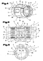
- FIG. 1 to 3 is a possible embodiment of a blocking sleeve 1 for a steering shaft 2 of a steering system 3 of a motor vehicle or on a footprint on wheels to be moved vehicle represents.
- a sleeve body 4 of the blocking sleeve 1 has a plurality of latching recesses 5, which are arranged on an outer side 6 of the sleeve body 4.
- the blocking sleeve 1 or the sleeve body 4 is designed as a hollow profile in the finished state in cross-section, wherein on an inner side 7 of the sleeve body 4 along a longitudinal center axis 8, a passage opening 9 extends.
- the passage opening 9 is delimited by a support surface 12 in at least one bearing section 10, which extends over at least part of a sleeve length 11.
- a peripheral contour 13 of the support surface 12 is formed corresponding to a circumferential contour 14 on an outer surface 15 of the steering shaft 2, wherein the peripheral contours 13, 14 preferably extend in a circular manner.
- the bearing portion 10 thus preferably forms an annular and cylindrical portion of the sleeve body 4.
- the hollow section-like cross-section of the blocking sleeve 1 is possible, wherein the bearing portion 10 with the support surface 12 of any contour shape, in particular a contour of an outer circumference of the steering shaft 2, and / or in the portion of the sleeve length 11 outside the bearing portions 10, the blocking sleeve 1 regardless of the cross-sectional shape may be formed in the bearing sections 10 or this as a square, eg square or triangular, hollow cross-section accordingly.
- the sleeve body 4 has two bearing sections 10, which are each formed on end faces 16, 17 of the sleeve body 4 facing away from one another.
- the two bearing sections 10 each extend from end edges 18, 19 in the end regions 16, 17 over a support width 20 in the direction of the opposite end region 16; 17 of the sleeve body 4.
- the bearing sections 10 extend over 5% to 50%, in particular 10 to 30%, of the sleeve length 11, wherein it is also possible that the bearing sections 10 are formed over the entire sleeve length 11 (see Fig. 14 ).
- the through hole 9 of the sleeve body 4 is penetrated in mounted on the steering shaft 2 position thereof, the bearing portions 10 of the sleeve body 4 abut with its inner support surface 12 on the outer surface 15 of the steering shaft 2 under the action of a contact pressure and the support surfaces 12 with the outer surface 15 form a frictional connection on the support width 20.
- the locking recesses 5 on the outer side 6 of the sleeve body 4 can be brought into engagement with a locking member 21 of the steering system 3, wherein the locking member 21 can be transferred into a release or blocking position.
- the locking member 21 is part of a steering lock 22 of the steering system 3, wherein the locking member 21 is mounted according to the illustrated double arrow 23 adjustable in the longitudinal lock 22 and a release position in which the locking member 21 is out of engagement with the recesses 5 or a blocking position in which the Locking member 21 engages in at least one of the recesses 5, is determined by the steering lock 22.
- the steering lock 22 On the construction of the steering lock 22 is not discussed in more detail here, since the structure and operation of such locking or locking devices for motor vehicle steering systems are already known from the prior art.
- the support surfaces 12 in the bearing portions 10 with preferably a plurality of lubrication pockets 24 which are recessed in the support surfaces 12 and which are suitable for receiving a lubricant or it is the support surface 12 at or between a lubricious structure (see Fig. 22 Us 23) formed on the inside 7 of the sleeve body 4 in the bearing portion 10.
- a lubricious structure see Fig. 22 Us 23
- Those lying on the inside of the bearing portion 10 areas in which the lubrication pockets 24 are arranged have a relation to the support surface 12 in the direction of the outer side 6 offset boundary surface 25, each enclosing a lubricating pocket 24.
- boundary surfaces 25 are offset in the case of annular or cylindrical bearing sections 10 relative to the support surface 12 in the radial direction to the longitudinal central axis 8 to the outside.
- bearing sections 10 with lubrication pockets 24 and the sliding structure are later in the course of Fig. 17 to 23 described in more detail.
- the recesses 5 of in Fig. 1 to 3 illustrated embodiment of a blocking sleeve 1 are each arranged between two adjacent, provided on the outer side 6 of the sleeve body 4 protrusions 26. It is generally noted that the latching recesses 5 form part of a profiled or structured surface 27 on the outside 6 of the sleeve body 4.
- the projections 26 are formed with respect to the surrounding, flat areas on the surface 27 on the outer side 6 of the sleeve body 4 projecting or raised.
- the projections 26 jump substantially radially on its longitudinal center axis 8 over a height 28, which is for example 3 to 5 mm, in particular approximately 4.5 mm, against the remaining, outer surface 27 before.
- a latching recess 5 is thus formed between two adjacent projections 26, wherein the latching recesses 5 are delimited by opposing stop surfaces 29a, 29b of two projections 26 which are respectively arranged on longitudinal side portions 30a, 30b of the projections 26.
- the protrusions 26 extend in the longitudinal direction along an extension axis 31 running parallel to the longitudinal central axis 8 of the sleeve body 4 over a length 32.
- a latching width 33 of the latching recess 5 extending between the opposing abutment surfaces 29a, 29b is determined by a width 34 of the protrusions 26 and the number of circumferentially on the outer side 6 of the sleeve body 4 arranged protrusions 26.
- the locking width 33 is dimensioned so that that the locking member 21, in particular a locking pin 35, can protrude into the latching recess 5 and preferably without clearance or with a small tolerance by the stop surfaces 29a, 29b limited if the locking member 21 of the steering lock 22 is in the locked position.
- the locking pin 35 has for this purpose in particular parallel locking surfaces 36a, 36b, which abut in the blocking position of the stop surfaces 29a, 29b.
- the protrusions 26 have a trapezoidal cross-sectional shape or circumferential contours, wherein the abutment surfaces 29a, 29b on a respective projection 26 for this purpose are at an angle 37 to each other, which preferably converges sharply in the direction of the inner side 7 of the sleeve body 4.
- a radial axis 38, along which the projections extend over the height 28, is directed normal to the longitudinal central axis 8 of the sleeve body 4.
- the protrusions 26 each have a top surface 39 which is normal or oblique to the radial axis 38 and is spaced by the height 28 of the surrounding surface 27, wherein the abutment surfaces 29a, 29b of the projections 26 from the top surface 39 in the direction of Radial axis 38 toward the passage opening 9 according to the angle 37 extend to taper each other.
- the abutment surfaces 29a, 29b on a projection 26 extend at an angle 37 to one another such that the stop surfaces 29a, 29b of two adjacent projections 26, which are distanced from each other by way of the latching width 33, run parallel to one another.
- Such a parallel arrangement of the abutment surfaces 29a, 29b advantageously allows the use of locking pins 35 with parallel locking surfaces 36a, 36b, as used in the prior art.
- the projections 26 may also have other cross-sectional shapes, for example, the stop surfaces 29a, 29b on a projection 26 parallel or at an angle 37, which widens dull towards the inner side 7 of the sleeve body 4, whereby the projections 26th may have rectangular or any frusto-conical cross-sectional shapes.
- the latching recess 5 is formed in a U-shaped or trough-shaped in cross-section with trapezoidal projections 26, wherein as noted above, this may also have a truncated or trapezoidal or rectangular cross-sectional shape. It only has to be ensured that the locking member with its locking surfaces 36 a, 36 b clearance or almost free of play on the stop surfaces 29a, 29b can be brought to bear.
- the sleeve length 11 is thus composed of the over the length 32 extending projections 26 and at least a portion of the remaining sleeve length 11 engaging bearing portions 10 with the support surfaces 12 together.
- a cavity 40 is disposed within the projections 26, which extends in the form of a recess 41 from the inner side 7 of the hollow body 4 in the direction of its outer side 6, wherein the recess 41 on the inner side 7 like a groove or trough with a Inner surface 42 runs.
- An inner contour of the recess 41 on the inner surface 42 and the outer contour of the projection 26 are preferably uniformly formed, wherein the projections 26, for example, the shape of a U- or C-profile or the like.
- the projections 26 may thus have a Trapezhohlprofil cross-section.
- a wall thickness 43 of the sleeve body 4 may have a uniform dimension in the region of the projection 40 having the cavity 40 and the rest of the sleeve body 4.
- the wall thickness 43 of the sleeve body 4 is for example between 0.3 and 5 mm, in particular 0.5 to 3 mm, preferably 1 to 2 mm.
- their wall thickness 43 may be smaller than the rest of the sleeve body 4, in particular due to material stretch, for example the wall thickness 43 of the projections 26 may be between 1/4 and 3/4, in particular between 1/3 and 2 /. 3 or approximately in the range of half the wall thickness 43 of the rest of the sleeve body 4 are.
- the sleeve body 4 is preferably formed of a uniform material, in particular of steel, aluminum or of a suitable metallic alloy. It is possible that the sleeve body 4 is replaced by a e.g. by means of pressure forming, in particular extrusion, made, seamless tube profile is formed, in which the corresponding recesses 5 are attached. Preferably, however, the sleeve body 4 is formed from a formed, platinum-like blank, which is brought into a hollow profile-like shape and by means of a connecting element 44 which is mounted in a parting line 45 between two longitudinal side edges 46 and 47, connected to a closed hollow profile, as will be described in more detail later.
- the sleeve body 4 in turn has latching recesses 5 on its outer side 6, wherein the latching recesses 5 are limited by the closed stop surface 29.
- the cutouts 48 are formed as over the entire wall thickness 43 of the sleeve body 4 extending material breakthroughs, which, for example, slot-like elongated rectangular or oval shape along the extension axis 31 longitudinally formed.
- the latching recesses 5 are enclosed by circumferential webs 49, which extend over an extent 50 in the radial or oblique direction onto the longitudinal central axis 8 along the radial axis 38 of the hollow body 4 toward the interior of the sleeve body 4.
- a peripheral edge 51 delimiting the cutout 48 is preferably closed over the circumference thereof and in particular is formed oval, annular, rectangular or the like, so that the latching recess 5 extends longitudinally in the sleeve body 4.
- the hollow profile-like sleeve body 4 has over a portion 52 of the sleeve length 11 a preferably full widening 53 or bulge.
- a diameter 54 of the widening 53 is greater than a diameter 55 at the regions lying outside of the partial section 52, wherein in the case of non-cylindrical widening 53, the linear dimensions are correspondingly formed.
- the regions which are recessed radially relative to the widening 53 relative to the longitudinal center axis 8 are at least partially formed by the bearing sections 10, which on the sleeve body 4 have the support surfaces 12 on the inside for frictionally engaging the steering spindle 2.
- the cutouts 48 are arranged in the section 52 in a row running around the circumference of the sleeve body 4, wherein the extension axis 31, along which the slot-like latching recesses 5 extend, preferably extend parallel to the longitudinal central axis 8 of the sleeve body 4.
- end surfaces 56 of the circulation ribs 49 are preferably formed such that the extending through the through hole 9 steering spindle 2 is supported on this or a slight gap between the outer surface 15th the steering shaft 2 and the end surfaces 56 is formed.
- the end faces 56 are therefore preferably bounded by an enveloping body 57, in particular an enveloping cylinder, which has the peripheral contour 14 of the steering spindle 2 in the region of the widening 53.
- the end faces 56 are thus each formed along the circumference of the enveloping body 57 extending.
- envelope body diameter 58 corresponds to the inner diameter 59 in the region of the bearing sections 10 or is slightly larger than the inner diameter 59 is thus advantageous, so that a steering spindle 2 projecting through the passage opening 9 is supported by the end faces 56 in the section 52 on its outer surface 15 becomes.
- the outer surface 15 of the steering spindle 2 facing end surfaces 56 can thus limit a rash or a deflection of the steering shaft 2 from a parallel to the longitudinal central axis 8 normal position.
- a locking member 21 of a steering lock 22 engage, thus positioning the steering shaft 2 against rotation of the same.
- the stop face 29a, 29b is enlarged relative to the surface otherwise extending only over the wall thickness 43 by forming circumferential webs 49, so that the surface pressure between this and the locking surfaces 36a, 36b of the locking bolt can be reduced and a stiffening of the slot-like recess 5 is achieved becomes.
- the circulation webs 49 are formed by forming the lying around the cutouts 48 areas, which is done without cutting by expanding or compressing these areas in the direction of the interior of the sleeve body 4.
- Fig. 7 is another embodiment of a steering system 3 and a steering shaft 2 arranged blocking sleeve 1 shown.
- the inner support surface 12 enters into a frictional connection with the outer surface 15 of the steering shaft 2.
- the bearing section 10 is arranged on a first end region 16 of the two end regions 16, 17 of the sleeve body 4 facing away from one another, wherein this bearing section 10 is attached to the steering shaft 2 with a clamping voltage.
- the further end region 17 is preferably free of internal, resulting from a material deformation stresses on a further region of the outer surface 15 of the steering shaft 2 adjacent or arranged with a slight gap of this distanced.
- the steering spindle 2 has in the illustrated embodiment, a first spindle diameter 60a and a further spindle diameter 60b, wherein the larger spindle diameter 60b is tapered by a shoulder 61 on the small spindle diameter 60a radially in the direction of the longitudinal central axis 8.
- the sleeve body 4 rests in the bearing portion 10 with the inner diameter 59a on the steering shaft 2 in the region of the first, smaller diameter 60a with the clamping voltage, and it extends the rest of the sleeve body 4 in the direction of the longitudinal center axis 8 on the shoulder 61 of the steering shaft 2 across The further, larger spindle diameter 60b over an overlap region 63.
- the attachment of the blocking sleeve 1 on the steering shaft 2 is preferably carried out exclusively on the bearing portion 10.
- the recesses 5 are attached in the opposite of the inner diameter 59a in the bearing portion 10 via a shoulder 62 extending over the portion 52 extending widening 53 on the sleeve body 4, the recesses 5 are attached.
- the hollow profile-like sleeve body 4 extends over the partial section 52 substantially cylindrical, wherein polygonal cross-sectional shapes of the sleeve body 4 in the section 52 are possible.
- the or the bearing portions 10 are formed with respect to the remaining portion 52 with the widening 53 as circumferential, ring-like collars.
- a heel 61 of a steering shaft 2 With an in Fig. 7 illustrated steering system 3, the bridging a heel 61 of a steering shaft 2 is possible, with the sleeve body 4 can be supported in the overlapping region 63 on the steering shaft 2 to stabilize it.
- the blocking sleeve 1 can at least partially as in the Fig. 1 to 6 be described described.
- a further embodiment of a blocking sleeve 1 is shown, which is attached to a steering shaft 2.
- the sleeve body 4 in turn has a bearing section 10 in the first end portion 16 which frictionally rests on the support surface 12 on the outer surface 15 of the steering shaft 2, wherein prevails in the bearing portion 10 sleeve body 4, an internal stress or clamping voltage.
- the sleeve body 4 has the opposite to the collar-like bearing portion 10 with the inner diameter 59 a radially widened widening 53, which extends over the portion 52 in the direction of the longitudinal central axis 8.
- a plurality of latching recesses 5 are again arranged, which are realized in the form of slot-like material openings over the wall thickness 43 of the sleeve body 4.
- a respective circumferential web 49 extends over the extent 50 in the radial direction along the radial axis 38 toward the interior of the sleeve body 4.
- the peripheral edge 51 facing the interior of the sleeve body 4 and the stop surface 29 of the circumferential web 49 have an open contour on. The circumferential web 49 thus encloses only a portion of the slot-like recess 5.
- FIGS. 9 and 10 a further embodiment of a blocking sleeve 1 is shown, which is attached to a steering shaft 2.
- the latching recesses 5 are in turn formed by cutouts 48, which are enclosed by a respective circumferential web 49.
- the peripheral edge 51 and stop surface 29, which limit the cutout 48, have a closed contour.
- the circumferential webs 49 extend in a direction away from the interior or the passage opening 9 of the sleeve body 4 substantially parallel to the course on the normal to the longitudinal central axis 8 extending radial axis 38.
- the end face 56 and the peripheral edge 51 are thus by the extent 50 relative to the surrounding outer surface 27 of the sleeve body 4 distanced.
- the stop surface 29 delimiting the cutout 48 preferably extends parallel to the radial axis 38.
- the remaining regions on the sleeve body 4 outside of the circumferential land 49 have a planar, in particular cylindrical, outer surface 27.
- the bearing portions 10 may be formed with the inner support surface 12.
- the outer vertex surface 67 of the raceway nose 66 lies substantially on an enveloping circle 68 tangent to the side edges of the end faces 56 of the circumferential webs 49, wherein the enveloping circle 68 extends concentrically to the longitudinal central axis 8 of the sleeve body 4.
- a nose width 69 is dimensioned such that widths 70, 71 of spaces 72, 73 lying adjacent to each running nose 66 in the intermediate region 65 are smaller than a locking pin width 73 of the locking bolt 35 which extends between the locking faces 36a, 36b. An undesired locking of the locking pin 35 in the intermediate region 65 between two adjacent circumferential webs 49 can thus be prevented.
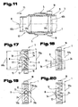
- FIG. 11 Another, possible embodiment of a steering system 3 with the steering shaft 2 and the lock sleeve 1 is mounted in this Fig. 11 shown.
- a bearing section 10 is formed which engages in each case with the support surface 12 on the outer surface 15 of the steering shaft 2 a frictional connection.
- the assembly of the blocking sleeve of the steering shaft 2 is carried out by sliding or mounting this according to the direction shown by arrow 75.
- the steering shaft 2 has a first region with the first, smaller diameter 60a and the further region with the further, larger diameter 60b, wherein the shoulder 61 is formed between these regions.
- the first, smaller diameter 60a of the steering shaft 2 is dimensioned such that it is at least slightly smaller than the inner diameter 59a of the blocking sleeve 1 in the bearing portion 10, so that the support surface 12 of the blocking sleeve 1 with the outer surface 15 of the steering shaft 2 in the area with the smaller diameter 60a which is not in direct contact with the sliding or mounting or has a sliding contact with a low coefficient of sliding friction.
- a frictional connection between the blocking sleeve 1 and the steering shaft 2 is formed only in the region of the steering shaft 2 with the larger diameter 60b.
- a material abrasion at the Support surface 12 and the outer surface 15 can thus be avoided over wide areas or at least kept low.
- FIGS. 12 and 13 a further embodiment of the blocking sleeve 1 is shown, wherein on the outer side 6 of the sleeve body 4, the locking recesses 5 are each arranged between two adjacent projections 26.
- the projections 26 are in a similar manner as in the Fig. 1 to 3 described trained and may in particular each have the inner cavity 40.
- a pitch angle 80 by which the adjacent, strip-like projections 26 on the outer circumference or the surface 27 of the sleeve body 4 are spaced apart, so that a much larger number of projections 26 around the circumference of the outer side 6 of the sleeve body 4 is arranged.
- the pitch angle 80 is 45 °, in the in FIGS. 12 and 13 illustrated embodiment, this is smaller than 45 °.
- Possible pitch angles 80 may be values between 5 and 60 °, in particular between 10 and 45 °.
- locking pin 35 Trained as a locking pin 35 locking member 21 of the steering lock 22 of the steering system 3 is formed in the locked position for simultaneous engagement in a plurality of recesses 5.
- the locking pin 35 has a plurality of latching teeth 81, which protrude into the latching recess 5 in the blocking position.
- Each detent tooth 81 has two locking surfaces 36a, 36b which come into contact with the respective stop surfaces 29a, 29b delimiting the detent recess 5.
- the high number of projections 26 and the engagement in the recesses 5 by a plurality of ratchet teeth 81 is advantageous because a reduction in the height 28 of the projections 26 and the division of the supporting force, which is proportional to a torque transmitted via the steering shaft 2 , On stop surfaces 29a, 29b of several projections is possible.
- the projections 26 and the recesses 5 are formed on the outer side 6 of the sleeve body 4, for example in the manner of a splined or serrated profile.
- the height 28 of the projections 26 can thus be reduced to half, in particular one third, preferably one quarter.
- FIG Fig. 14 Another variant of a blocking sleeve 1 is shown in FIG Fig. 14 shown.
- the support surface 12 with the lubricating pockets 24 or the slidable structure on the inner side 7 of the sleeve body 4 in this case runs continuously over the entire sleeve length 11.
- the projections 26 are formed from solid material, without internal cavities. The projections 26 extend like a strip or tooth along their extension axis 31 over the length 32 on the outer side 6 of the sleeve body 4.
- the strip-shaped protrusions 26 may be externally mounted on the cylindrical or annular sleeve body 4, for example via a connecting element, by removal of Material for forming the recesses 5 are formed, or are formed integrally with the rest of the sleeve body 4 in a primary molding process.
- the sleeve body 4 is formed from a profiled blank or sheet metal part, wherein on the profiled surface of the blank, the projections 26 and locking recesses 5 are formed.
- the profiled surface of the blank can be formed for example in the form of a serration.
- a method for producing a blocking sleeve 1 from a profiled blank is in the course of FIGS. 32 to 34 described in detail.
- the projections 26 can extend on the outside over the entire sleeve length 11 of the sleeve body 4 and the inside of the sleeve body 4, regardless of the projections 26, a structure, in particular the support surface 12 with the lubricating pockets 24 and the slidable structure formed can be. It is therefore possible that the bearing portion 10 is formed with the support surface 12 over the entire sleeve length 11. Since the inner side bearing portion 10 and the outer side projections 26 overlap with the length 32 over the sleeve length 11 or at least a part thereof, the sleeve length 11 and the weight of the blocking sleeve 1 can be reduced in an advantageous manner.
- FIGS. 15 and 16 A further embodiment of a blocking sleeve 1 or steering system 3 is in the FIGS. 15 and 16 shown.
- a sprocket 84th On the outer side 6 of the sleeve body 4 is a sprocket 84th provided, which has between teeth 85 arranged recesses 5.
- the latching recesses 5 are bounded by the stop surfaces 29a, 29b on the longitudinal side areas 30a, 30b of the teeth 85.
- the ring gear 84 is formed in the manner of a bevel gear and form the teeth 85 a fully extending, preferably fine straight or helical teeth around the sleeve body 4, so that a tooth or locking profile for positive engagement with the locking member 21 is provided.
- the widening 53 radial to its longitudinal central axis 8, which extends over the partial section 52 of the sleeve length 11, wherein the widening 53 expediently has a triangular or trapezoidal hollow cross section.
- the teeth 85 of the ring gear 84 are formed by projections and recesses, which along the extension axis 31 along.
- the inner side 7 of the sleeve body 4 can be recessed in the region of the widening 53 with respect to the surrounding regions, wherein the widening 53 is preferably produced in a non-cutting manner by bulging, pulling or bending material of the sleeve body 4 in the radial direction onto the longitudinal central axis 8.
- blocking member 21 is axially displaceable along the longitudinal central axis 8 of the blocking sleeve 1 and the concentric steering spindle 2 - according to the direction shown by an arrow 87, wherein the locking member 21 has a preferably bevel gear ring gear 88 which includes the ratchet teeth 81.
- the locking member 21 is formed rotationally fixed about the longitudinal center axis 8 and in the release position out of engagement with the locking recesses 5 of the blocking sleeve 1 and not coupled to the steering shaft 2.
- FIG. 15 a further possibility of an embodiment of the inner side 7 of the hollow profile-like sleeve body 4 is shown, in which this is formed in the bearing section 10 at least over a portion of the support surface 12 by the slidable structure 89, said closer in the course of FIGS. 22 and 23 is described.
- the sleeve body 4 in at least one connecting portion 82 via a running in the parting line 45 connecting element 44 is inextricably linked to an at least partially closed hollow profile, which is formed from one or more parts.
- the parting line 45 extends in each case between two opposite longitudinal side edges 46, 47, which are spaced from each other by a gap width 83.
- the connecting element 44 is preferably formed by a weld, for which purpose in particular a laser or plasma welding seam can be used due to the low-distortion connection process.
- the connection element may further be formed by an adhesive layer, a solder connection or the like, such connection methods being known from the prior art.
- the sleeve body 4 is generally noted that this may consist of only a single adherend, as shown in the figure, wherein this has a hollow profile-like shape, in particular an at least partially cylindrical or annular shape and in the connecting region 82, the parting line 45 via the sleeve length 11 runs continuously.
- the sleeve body 4 it is also possible for the sleeve body 4 to be formed from a plurality of joining parts connected to one another in connection areas 82 to form a closed hollow profile. Each joining part is inextricably connected to two connecting regions 82 via a connecting element 44 with the adjacent joining parts.
- the bearing portion 10 that this inside the region of the through hole 9, the support surface 12 which is frictionally fastened or fastened to the outer surface 15 of the steering shaft 2, as already described above has been.
- the frictional engagement between the support surface 12 and the outer surface 15 is achieved in that the sleeve body 4 is mounted in the bearing portion 12 with a clamping voltage to the steering shaft 2.
- this clamping voltage is generated by deformation of at least one of the two adjoining parts, ie sleeve body 4 or steering shaft 2, in the region of the bearing portion 10, so that in the deformed part an internal stress, in particular tensile stress, is caused.
- It is for example possible to produce the clamping voltage by widening the relative to the support surface 12 inside the steering shaft 2 or a shrinking of the bearing portion 10 of the sleeve body 4 on the outer surface 15 of the steering shaft 2.
- the generation of the clamping voltage is effected by plastic deformation of the bearing portion 10 of the sleeve body 4 in the direction normal to the longitudinal central axis 8 of the sleeve body 4, wherein the steering shaft 2 with the outer surface 15 remains unchanged in shape.
- the original form of the bearing portion 10 of the blocking sleeve 1 describes that shape in which the blocking sleeve 1 as manufactured, loose individual part and not yet applied to the steering shaft 2 or was postponed.
- connection strength of the frictional engagement between the support surface 12 press-fitted to the outer surface 15 of the steering spindle 2 in the bearing section 10 of the blocking sleeve 1 is such that the frictional engagement dissolves upon exceeding a limit torque value corresponding to the maximum frictional force and the steering spindle 2 slips in the connection.
- the connection strength and the limit torque value of frictional connection is determined by the coefficient of static friction, as well as the effective contact surface of this compound, which is determined by the support width 20, the inner diameter 59a and the surface portion of the recessed in the support surface 12 lubrication pockets 24.
- This limit torque value is, for example, in the range of 50 to 300 Nm, in particular about 100 to 200 Nm.
- the inner diameter 59a of the bearing portion 10 of the blocking sleeve 1 that this in the original form relative to the spindle diameter 60a, 60b of the steering shaft 2, an undersize of, for example 0.1 to 1 mm, in particular 0.2 to 0.7 mm, preferably 0th , 3 mm to 0.5 mm, so that when mounting or pushing the blocking sleeve 1 on the steering shaft 2, a plastic deformation of the bearing portion 10 in the radial direction on the longitudinal central axis 8 takes place.
- Lubrication pockets 24 are each suitable for receiving a lubricant, which can be used as lubricants friction-reducing lubricating oils, lubricating greases or solid lubricants, especially synthetic high performance lubricants.
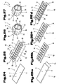
- Possible embodiments of the arrangement of the lubricating pockets 24 in the support surface 12 in the bearing portion 10 are in the Fig. 17 to 21 shown, wherein the inside 7 of the Sleeve body 4 in the bearing sections 10 has a corrugation or profiling or perforation.
- the boundary surface 25 surrounding the lubrication pockets 24 may have a circular arc-like, triangular, rectangular or trapezoidal or similar cross-sectional contours.
- a depth of the lubricating pockets 24, over which the boundary surface 25 of the lubricating pockets 24 is recessed relative to the support surface 12, is for example 0.05 to 1 mm, in particular 0.1 to 0.5 mm, preferably 0.1 to 0.3 mm.
- the introduction of the lubricating pockets 24 in the support surfaces 12 can be carried out in a non-cutting primary forming process or by cutting material removal, for example, butting, milling or the like.
- the lubrication pockets 24 may be arranged distributed uniformly or symmetrically on the peripheral contour 13 of the support surface 12, wherein each adjacent lubrication pockets the same distance 78 are spaced from each other.
- an uneven or asymmetrical distribution of the lubrication pockets 24 in the peripheral contour 13 of the support surface 12 is possible.
- the lubricating pockets 24 are each formed by groove-like or groove-like recesses which extend at an angle 76 transversely to the longitudinal central axis 8 of the blocking sleeve 1 over the entire support width 20 along its longitudinal axis 77.
- a second possible embodiment of an arrangement of the lubrication pockets 24 is shown on the support surface 12, wherein the lubrication pockets 24 extend parallel to the longitudinal central axis 8 of the sleeve body 8 along the longitudinal axis 77.
- the Fig. 19 shows a third embodiment of a possible arrangement of the lubrication pockets 24 in the support surface 12, wherein these are each formed as a multi-limbed, serrated depressions.
- Each of the legs 79a, 79b extends in an obtuse or acute angle 76 to the longitudinal central axis 8 of the sleeve body 1.
- Fig. 20 is a fourth, possible embodiment of the lubrication pockets 24 shown in the support surface 12, in which these each angled according to the angle 76 to the longitudinal central axis 8 of the sleeve body 1 and each two adjacent lubrication pockets 24 butt or acute angled to each other.
- Fig. 20 is a fourth, possible embodiment of the lubrication pockets 24 shown in the support surface 12, in which these each angled according to the angle 76 to the longitudinal central axis 8 of the sleeve body 1 and each two adjacent lubrication pockets 24 butt or acute angled to each other.
- a fifth possible embodiment of an arrangement of the lubrication pockets 24 is shown on the support surface 12, wherein the lubrication pockets 24 are formed in the support surface 12 as round and / or elliptical depressions irregularly over the bearing portion 12 on the circumference of the sleeve body 4 on the inside 7 are arranged distributed.
- the lubrication pockets 24 in the support surface 12 in the form of microstructures, such as irregular, very small depressions formed.
- the lubrication pockets 24 are formed in the newly formed support surface 12 by profiled valleys profile troughs of the actual profile of the support surface 12, wherein the actual profile or surface roughness profile has a mean surface roughness of 0.2 to 200 microns ,
- FIGS. 22 and 23 is a sixth possible embodiment of an embodiment of the inside 7 of the sleeve body 4 shown in the bearing section 12, wherein the sleeve body 4 is formed on the inside 7 in the bearing section 10 at least over a partial area by the known sliding structure 89, at which the support surface 12th is formed or adjacent to the support surface 12 extends.
- the slidable structure 89 is preferably one piece, in particular insoluble, connected to the sleeve body 4 and it forms this lying on the inside 7 of the sleeve body 4 sliding layer in the bearing section 10.
- the slidable structure 89 may be formed by a surface applied to the sleeve body 4 coating, in particular a sheet metal coating or the like, or be applied in the manufacture of the inside 7 of the sleeve body 4 in the bearing section 10 area.
- the material of the coating is selected such that a contiguous material pairing between the steering shaft 2 and blocking sleeve 1 forms a low coefficient of friction.
- a lubricious structure 89 may be provided on the inner side 7 of the sleeve body 4, which is produced by a surface finishing process, for example thermally or chemically curing, phosphating, nitriding, so that the lubricious structure 89 forms a finished support surface 12.
- the steering shaft 2 has a coating or treated surface, for example, that the steering shaft 2 in cooperation with the blocking sleeve 1 friction-reducing sliding layer with the outer surface 15 in Aufschiebeabrough for the blocking sleeve 1 and / or the steering shaft 2 in the region of an attachment point of the blocking sleeve 1 has a friction in cooperation with the blocking sleeve 1 friction layer.
- one of the in the Fig. 17 to 23 illustrated embodiments in combination with one of the embodiments of a blocking sleeve 1, as this in the Fig. 1 to 16 may be formed, ie, the bearing portions 10 of the sleeve body 4 in Fig. 1 to 16 as in one of the in Fig. 17 to 23 is described, may be formed.
- An independent solution of the object of the invention relates to the steering system 3 of a motor vehicle comprising the steering lock 22 with the releasable or blocking position convertible locking member 21 and the steering shaft 2 with the blocking sleeve 1 arranged on this.
- the blocking sleeve 1 is mounted with a clamping voltage for producing a frictional connection in the bearing portion 10 of the blocking sleeve 1 on the steering shaft 2, wherein the locking member 21 is in the blocking position of one of the recesses 5 of the blocking sleeve 1 is preferably in liquid form.
- Fig. 24 to 38 are possible variants of procedures for the production of several locking recesses 5 for a locking member 21 of the steering system 3 having blocking sleeve 1, which may be formed as described above, is shown.
- at least one of the recesses 5 exhibiting, platinenartiges blank 90, in particular sheet metal part 91, formed by forming a hollow profile in cross-section, in particular tubular, sleeve body 4 with at least one parting line 45 and the sleeve body 4 at each parting line 45 via a connecting element 44 to a closed hollow profile connected.
- a first example of a procedure for the production of the blocking sleeve 1 for steering systems 3 is shown, wherein the blocking sleeve 1 preferably according to the in Fig. 1 to 3 or 12 and 13 illustrated and described embodiments is formed.
- a plurality of recesses 5 are mounted on the sleeve body 4 of the blocking sleeve 1, with which the locking member 21 of the steering system 3 can be brought into engagement and it is at least one hollow profile, in particular cylindrical bearing portion 10 of the sleeve length 11 is formed, the frictionally or with a clamping voltage the steering shaft 2 of the steering system 3 can be attached.
- Fig. 24 is a platinum-like blank 90, in particular sheet metal part 91, shown, which is formed on the inside 7 or outside 6 planar or planar. It is now possible that in a first method step according to Fig. 24 the protrusions 26 are formed on the blank-like blank 90, wherein the protrusions 26 preferably in a row next to each other on a blank length 92 of the blank 90, each spaced by a constant distance 93 on the blank length 92 from each other, are arranged.
- a blank width 94 which preferably corresponds to the sleeve width 11 of the manufactured blocking sleeve 1, extends the at least one bearing portion 10, which extends over the entire blank length 92, in particular along the longitudinal side edges 95, 96.
- the projections 26 are formed via the height 28 perpendicular to the outer side 6 of the blank 90.
- the shapes of the projections 26 is preferably carried out in a non-cutting forming process, as this the Fig. 25a to 25c is shown in detail.
- the platinen shame blank 90 in a first forming step according to Fig. 25a brought into a continuous across the cutting width 94 waveform corresponds, for example, a sinusoidal or Zacken- or rectangular shape.
- the inner or outer side 6, 7 of the corrugated blank 90 thus has raised or lying between these recessed areas, wherein in the recessed areas or bulges on the inside 7 in a further forming step after Fig. 25b the projections 26 are formed in the direction of the outer side 6.
- the shaping of the projections 26 takes place, for example, by deep-drawing, wherein a corresponding deep-drawing tool consists of a punch and a die and the production of the final form of the projections can take place in several passes.
- thermoforming tool which is not shown in detail, it should be noted that the stamp in the manner of a contour variable expansion dome or the die may be formed in the form of a contour variable expansion die, with the undercut forms of projections 26, for example, the trapezoidal projections 26 shown, can be produced, such thermoforming tools from the prior Technics are known and will not be discussed in more detail here on this point.
- the corrugated region at the longitudinal side edges 95, 96, in which the bearing sections 10 are to be formed is in turn formed back into a planar or planar shape. This is done for example by Eben allergy or Ebenpressen exclusively in the region of the longitudinal side edges 95, 96 in the later bearing sections 10th
- a further process step Fig. 25d can be done attaching the lubricating pockets 24 or the known sliding structure 89 on the inside 7 at the bearing portions 10, wherein this in the case of the lubrication pockets 24, for example by cutting material removal, in particular by milling, bumping, erosion or the like., Or without cutting through Urformen can be done and in the case of the lubricious structure 89 by applying a coating, in particular sheet metal coating, or processing of the support surface 12 in a surface treatment process or surface finishing process can be carried out.
- the lubricating pockets 24 or the slidable structure 89 in an earlier process step, for example on the platinum-like blank 90 after Fig. 19 , or a later method step, for example on the hollow profile-like sleeve body 4 according to FIGS. 21 and 22 to be attached.
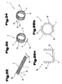
- the forming in the hollow profile-like shape of the sleeve body 4, which is preferably substantially cylindrical, can be done by rolling the blank 90 around a mandrel, until the through hole 9 in the Inner of the sleeve body 4 is formed and in the bearing portions 10 an annular or cylindrical shape is made.
- the rolling of the platinum-like blank to the hollow profile-like sleeve body 4 can be done in several forming or bending steps, as shown schematically in the Figs. 26a and 26b is shown.
- the blank-like blank 90 can be brought into a U-shape or circular arc-like shape, and in one or more further forming steps, the blank 90 can be brought into a cylindrical or circular shape enclosing the mandrel.
- Tools for such a rolling-in process are known from the prior art, wherein in particular the mandrel and a drive, in particular a wedge drive, are used for the automated production of the mandrel body 4 enclosing the mandrel.
- the hollow profile-like sleeve body 4 after performing the method step according to Fig. 26 the parting line 45 which extends between two opposite longitudinal side edges 46, 47.
- connection region 82 the connecting region 82 with the connecting element 44 has a higher strength, for example a tensile strength or yield strength higher by 100 to 400%, in particular 200 to 300%, than the material from which the rest of the sleeve body 4 is formed.
- the material of the sleeve body 4 is preferably selected from a group of materials in which the material of the weld in the solidified state after structural change in the connecting portion 82 has a higher yield strength and tensile strength than the remaining material of the sleeve body 4 and the base material as already described above.
- the strength of the weld produced by laser or plasma welding is compared to the rest of the sleeve body 4 while percent or relatively higher than the strength reduction caused by the reduced wall thickness 43 in the connection area.
- connection region 82 A break in the connection region 82 can thus be prevented in the case of plastic deformation in the bearing section 10 of the sleeve body 4.
- the yield strength of the blocking sleeve 1 outside the connection region is approximately 250 N / mm 2 and the yield strength of a connecting element 44 formed as a weld is approximately 700 N / mm 2.
- FIG. 28 to 31 Another possible procedure for producing a blocking sleeve 1 is in the Fig. 28 to 31 illustrated, wherein the blocking sleeve 1 preferably according to the in 4 to 6 is designed and described embodiments designed.
- the platinum-like blank 90, in particular sheet metal part 91, as in accordance with Fig. 28 is shown in a process step to Fig. 29 provided with the recesses 5. This is done in a separation process, in particular punching process, by extending over the wall thickness 43 of the platinum-like blank 90 extending material openings 97 are cut, as in Fig. 29a shown. These material breakthroughs 97 are spaced apart by the distance 93 over the blank length 92 in a row parallel to each other.
- the areas surrounding the material openings 97 on the platinum-like blank 90 are each formed into one of the circulating webs 49.
- the forming of the circumferential webs 49 is carried out by bending or widening of the areas lying around the material cutouts, so that according to the embodiment shown by the circulating webs 49 limited locking recesses 5 are formed with the inner stop surface 29.
- the peripheral edge 51 or stop surface 29 may have an oval, annular or rectangular, the catch recess 5 limiting, closed contour or an open contour.
- the forming of the circumferential webs 49 can be done by reducing the wall thickness 43 of the blank 90 due to material stretching or by bending of individual, tab-like circulating webs 49 while maintaining the wall thickness 43 done.
- the expansion 53 on the blank 90 can be formed, for which purpose the bearing sections 10 of the blank width 94 surrounding the widening 53 are reset relative to the widening 53, in particular by retraction of the bearing sections 10 or bulging of the widening 53 of the shoulder 62.
- a trough-like, recessed course of the widening 53 on the inside 7 of the blank 90 is formed over part of the blanking width 94, the widening 53 being continuous over the blanking length 92.
- FIGS. 32 to 37 is another possibility of a procedure for producing the blocking sleeve 1, in particular after Fig. 14 is formed.
- a platinum-like blank portion 90 used which has a profiling 98 on the outside 6 and on the inside 7 is formed planar or planar.
- the production of locking recesses 5 can be omitted, since they are already formed between the projections 26 of the profiling 98.
- a sheet-metal part 91 with a serrated profile 98 can be used.
- the bearing portion 10 over the entire blank width 94 and the entire sleeve length 11 is formed, for which purpose on the support surface 12 on the inside 7 of the blank 90 or sleeve body 4 in the support surface 12 recessed lubrication pockets 24 or per se known sliding structure 89 are arranged.
- Such a profiled blank 90 can in a method step according to Fig. 33 or a method step according to Fig. 37 are made to a closed, hollow profile-like sleeve body 4, wherein the rolling-in according to Fig. 26 or the arrangement of the connecting element 44 according to Fig. 37 can be done.
- FIGS. 35 to 38 show a further possibility of a procedure for producing the blocking sleeve 1, in particular according to FIGS. 15 and 16 is formed.
- the platinum blank 90 after Fig. 35 is hereby in a first step after Fig. 36 provided with the locking teeth 5 arranged between teeth 5 on the outer side 6, which extend over the length 32 over part of the blank width 94, so that a toothed or latching profile formed by a tooth 85 straight or helical teeth on the blank 90 becomes.
- the teeth 85 can be formed by cutting material removal, for example by milling, on the outside 6, so that the tooth or locking profile extends only on the outside 6 preferably over the entire blank length 92 and the inside 7 of the blank 90 is formed planar. It is also the use of an already profiled sheet metal part 91, as in Fig. 32 described, possible.
- the widening 53 is produced with the teeth 85 of the blank 90 over the section 52 of the blank width 94, wherein this can be done, for example, in a drawing process.
- the teeth 85 and locking recesses 5 are arranged on at least one of the angles 86 inclined to the surrounding areas flanks of the widening 53, wherein the widening 53 expediently a Triangular or Trapezhohlquerites has.
- the production of the hollow profile-like sleeve body 4, and the attachment of the connecting element 44 in the parting line 45 and the arrangement of the lubricating pockets 24 or the known sliding structure 89 is carried out, which can be done analogously to the above description.
- this has the fully encircling sprocket 84, which is formed in the manner of an inner bevel gear of a Kegelradcruung, as in FIGS. 15 and 16 described.
Landscapes
- Engineering & Computer Science (AREA)
- Mechanical Engineering (AREA)
- General Engineering & Computer Science (AREA)
- Steering Controls (AREA)
- Sliding-Contact Bearings (AREA)
Abstract
Description
Die Erfindung betrifft eine Blockierhülse für eine Lenkspindel einer Lenkungsanlage eines Kraftfahrzeugs sowie eine Lenkungsanlage, wie in den Oberbegriffen der Ansprüche 1 und 9 beschrieben.The invention relates to a blocking sleeve for a steering shaft of a steering system of a motor vehicle and a steering system, as described in the preambles of
Es ist bei Lenkungsanlagen für Kraftfahrzeuge erforderlich, dass diese mit einer Vorrichtung zum bedarfsweisen Blockieren einer Drehbewegung einer Lenkspindel ausstattet sind, um eine ungewünschte Inbetriebnahme eines Kraftfahrzeuges durch Sperren des Lenkeinschlages an der Lenkungsanlage zu verhindern. Hierzu wird ein in eine Freigabe- oder Sperrstellung überführbares Sperrglied des Lenkschlosses mit einer an der Lenkspindel starr befestigten Blockierhülse in Eingriff gebracht, sodass aufgrund der gegen Verdrehung gesperrten Lenkspindel eine wirksame Diebstahlsicherung für das Kraftfahrzeug geschaffen wird. Um nun eine Beschädigung des Lenkschlosses oder der Lenkspindel durch einen Gewaltbruch aufgrund eines unzulässig hohen, an der Lenkspindel anliegenden Drehmomentes zu vermeiden, sind im Stand der Technik Vorrichtungen zum Sperren von Lenkungsanlagen bekannt, die eine nachgiebige Verdrehsperre mit einer Drehmomentbegrenzung aufweisen. Bei diesen Vorrichtungen kann die Lenkspindel ab einem gewissen Grenzdrehmoment gegenüber der Blockierhülse durchrutschen, wodurch eine Deformierung oder ein Bruch der Lenkspindel oder des Lenkschlosses verhindert wird.It is necessary in steering systems for motor vehicles that they are equipped with a device for blocking a rotational movement of a steering spindle as needed, to prevent unwanted startup of a motor vehicle by blocking the steering angle to the steering system. For this purpose, a releasable in a release or blocking position locking member of the steering lock with a rigidly attached to the steering spindle locking sleeve is engaged, so that an effective anti-theft device for the motor vehicle is created due to the locked against rotation steering shaft. In order to avoid damage to the steering lock or the steering shaft by a break in force due to an unduly high, applied to the steering shaft torque, devices for locking steering systems are known in the art, which have a resilient anti-rotation device with a torque limiter. In these devices, the steering shaft can slip against the blocking sleeve from a certain limit torque, whereby a deformation or breakage of the steering shaft or the steering lock is prevented.
Eine derartige Vorrichtung ist beispielsweise aus der
Nachteilig ist hierbei, dass bei der Montage einer bereits vorgefertigten, hohlprofilartigen bzw. rohrförmigen Hülse auf der Lenkspindel, was durch Aufschieben der Hülse auf die Lenkspindel erfolgt, aufgrund des durch die Klemmspannung zwischen Hülse und Lenkspindel entstehenden Reibschlusses ein gegenseitiger Materialabrieb an den Kontaktflächen erfolgt. Somit wird die Oberflächenqualität an der Lenkspindel und der Hülse, beispielsweise durch Riefenbildung, beeinträchtigt sowie die Festigkeit der reibschlüssigen Verbindung zwischen Hülse und Lenkspindel vermindert. Eine Reproduzierbarkeit von im Wesentlichen gleichen Verbindungsfestigkeiten zwischen Lenkspindel und Hülse ist aufgrund des unkontrollierbaren Materialabriebs nicht möglich.The disadvantage here is that in the assembly of an already prefabricated, hollow profile-like or tubular sleeve on the steering shaft, which is done by pushing the sleeve on the steering shaft, due to the resulting by the clamping voltage between the sleeve and the steering shaft frictional engagement a mutual material abrasion takes place at the contact surfaces. Thus, the surface quality of the steering shaft and the sleeve, for example, by scoring, impaired and reduces the strength of the frictional connection between the sleeve and the steering shaft. A reproducibility of substantially equal bond strengths between the steering shaft and sleeve is not possible due to uncontrollable material abrasion.
Aus der
Nachteilig ist hierbei, dass beim Aufschieben der Diebstahlsicherungsmanschette auf die Lenkspindel wiederum ein Materialabrieb an den Kontaktflächen erfolgt und eine Minderung der Oberflächenqualität und Verbindungsfestigkeit daraus resultiert.The disadvantage here is that when pushing the anti-theft cuff on the steering shaft again a material abrasion takes place at the contact surfaces and a reduction of the surface quality and connection strength results.
In der
Zudem wird von der Automobilindustrie gefordert, dass während eines Prüfzyklus, bei dem das Lenkrad mit verriegeltem Lenkschloss abwechselnd je einige Male, z.B. 5 mal, um 360° nach links und rechts gedreht wird, die nachgiebige Verdrehsperre weder blockiert noch das Drehmoment unter 100Nm absinkt. Dies stellt besondere Anforderungen an die Einrichtung zur Drehmomentbegrenzung.In addition, the automotive industry requires that, during a test cycle in which the steering wheel with locked steering lock be alternately turned off a few times, e.g. 5 times, 360 ° to the left and right is rotated, the resilient anti-rotation lock neither blocked nor the torque drops below 100Nm. This places special demands on the device for torque limiting.
Eine Blockierhülse für eine Lenkspindel einer Lenkungsanlage eines Kraftfahrzeuges ist auch aus der
Schließlich offenbart die
Aufgabe der Erfindung ist es eine Blockierhülse zu schaffen, die sich auf eine Lenkspindel einer Lenkungsanlage einfach montieren lässt. Die Blockierhülse soll in vorteilhafter Weise in einer Lenkungsanlage eines Kraftfahrzeugs verwendet werden.The object of the invention is to provide a blocking sleeve that can be easily mounted on a steering shaft of a steering system. The blocking sleeve should be used in an advantageous manner in a steering system of a motor vehicle.
Die Aufgabe der Erfindung wird durch die Merkmale im Anspruch 1 gelöst. Der Vorteil liegt darin, dass die Schmiertaschen im Lagerabschnitt der Blockierhülse zur Montage an der Lenkspindel mit einem Schmierstoff befüllbar oder benetzbar sind, wodurch der Gleitreibungskoeffizient zwischen Außenoberfläche der Lenkspindel sowie Stützfläche der Blockierhülse wesentlich herabgesetzt wird, die Bildung von Passungsrost zwischen den unter großer Flächenpressung stehenden Reibpartner Blockierhülse/Lenkspindel verhindert und das Aufschieben der Blockierhülse auf die Lenkspindel erleichtert wird. Ein gegenseitiger Materialabrieb bzw. ein Fressen zwischen Blockierhülse und Lenkspindel kann somit stark verringert bzw. verhindert werden, sodass die Oberflächenqualität an der Lenkspindel nach dem Aufschiebevorgang über die Aufschiebelänge nicht oder nur unwesentlich beeinträchtigt ist und die Festigkeit der reibschlüssigen Verbindung an der Montageposition der Blockierhülse auf der Lenkspindel nicht durch Beschädigung der Oberflächen im reibschlüssigen Verbindungsbereich beeinträchtigt wird. Weiters ist eine Reproduzierbarkeit der Verbindungsfestigkeit des genannten Reibschlusses gegeben, da der unkontrollierbare Einflussfaktor des ungleichmäßigen Materialabriebs beim Aufschieben der Blockierhülse auf die Lenkspindel wegfällt. Ein weiterer Vorteil besteht darin, dass auch nach durchlaufenem Prüfzyklus, d.h. nach ca. 5 erfolgten Lenkradumdrehungen je in Rechts- bzw. Linksrichtung, ein Reibschluss mit ausreichender Festigkeit zwischen Blockierhülse und Lenkspindel aufgebaut werden kann, sodass sich der Reibschluss bei in einem Kraftfahrzeug in Betrieb befindlicher Lenkungsanlage erst bei Übersteigen eines der maximalen Reibkraft entsprechenden Grenzdrehmomentwertes löst.The object of the invention is solved by the features in
Die Ansprüche 2 bis 7 beschreiben vorteilhafte und auf den Anwendungsfall abgestimmte Ausgestaltungen der Schmiertaschen im Lagerabschnitt.The
Gemäß den Ausgestaltungen nach den Ansprüchen 2 und 3 wird ein einfacher und effektiver Aufbau des innenliegenden Bereichs im Lagerabschnitt zur Speicherung und Abgabe eines Schmierstoffs erreicht, sodass einerseits während des Aufschiebens der Blockierhülse auf die Lenkspindel die Kontaktflächen mit einem Schmierstoff benetzt werden und andererseits die Stützfläche im Lagerabschnitt ausreichend groß bemessen ist, sodass diese in der Montagestellung eine reibschlüssige Verbindung mit der Lenkspindel, die eine ausreichende Festigkeit aufweist, eingehen kann.According to the embodiments according to
Die in Anspruch 4 angeführten Merkmale sind vorteilhaft, da durch einen abgewinkelten Verlauf der Schmiertaschen gegenüber der Längsmittelachse des Hülsenkörpers die Schmiertaschen über einen größeren Umfangsbereich innenseitig im Lagerabschnitt wirksam sind und eine Benetzung eines Umfangssegments an der Innenseite, das größer als eine Breite der Schmiertaschen ist, ermöglicht wird.The features cited in
Beispielsweise können gemäß Anspruch 6 die Schmiertaschen an der Stützfläche durch die Profiltäler des wirklichen Rauhigkeitsprofils der Stützfläche gebildet sein, sodass in entsprechend aufgerauten oder geglätteten Bereichen der Stützfläche der mit der Lenksäule auszubildende Reibungskoeffizient erhöht oder verringert werden kann.For example, according to
Durch eine Verteilung der Schmiertaschen um die Umfangskontur gemäß Anspruch 7 kann der Lagerabschnitt an der Innenseite bzw. die Lenkspindel an der Außenoberfläche beim Aufschieben großflächig, insbesondere vollumfänglich, mit Schmierstoff benetzt werden, wodurch der Aufschiebe- bzw. Montagevorgang der Blockierhülse verbessert wird.By distributing the lubrication pockets around the peripheral contour according to
Von Vorteil ist auch die Weiterbildung nach Anspruch 8, da durch die durchgängige Trennfuge unterschiedlichste und flexible Aufbauten des Hülsenkörpers aus einem oder mehreren Fügeteilen ermöglicht werden. Das Verbindungselement ist vorzugsweise durch eine Schweißnaht, wie Laser- oder Plasmaschweißnaht, insbesondere ohne Zusatzwerkstoff, gebildet.Another advantage is the development according to
Die Aufgabe der Erfindung wird auch durch die Merkmale im Anspruch 9 gelöst. Von Vorteil ist hierbei, dass an der Lenkungsanlage eine effektive Überlastsicherung für die Lenkspindel und das Lenkschloss geschaffen wird, deren Aufbau und Montage durch die Blockierhülse mit den vorstehend beschriebenen Vorteilen vereinfacht wird.The object of the invention is also solved by the features in
Die Erfindung wird im nachfolgenden anhand der in den Zeichnungen schematisch dargestellten Ausführungsbeispiele näher erläutert.The invention will be explained in more detail below with reference to the embodiments schematically illustrated in the drawings.
Es zeigen:
- Fig. 1
- eine erfindungsgemäße Blockierhülse in perspektivischer Schrägansicht;
- Fig. 2
- die Blockierhülse nach
Fig. 1 , geschnitten gemäß den Linien II-II; - Fig. 3
- die Blockierhülse nach
Fig. 1 im Längsschnitt; - Fig. 4
- eine weitere Ausführungsvariante einer erfindungsgemäße Blockierhülse in perspektivischer Schrägansicht;
- Fig. 5
- die Blockierhülse nach
Fig. 4 im Längsschnitt; - Fig. 6
- die Blockierhülse nach
Fig. 4 im Querschnitt; - Fig. 7
- eine weitere Ausführungsvariante der an einer Lenkspindel befestigten Blockierhülse im Längsschnitt;
- Fig. 8
- eine weitere Ausführungsvariante der an der Lenkspindel befestigten Blockierhülse im Längsschnitt;
- Fig. 9
- eine weitere Ausführungsvariante einer an einer Lenkspindel befestigten Blockierhülse im Querschnitt und Halbschnittdarstellung um eine waagrechte Symmetrieachse;
- Fig. 10
- die Blockierhülse nach
Fig. 9 im Längsschnitt; - Fig. 11
- eine mögliche Ausführungsvariante einer Lenkspindel mit auf dieser befestigten Blockierhülse im Längsschnitt;
- Fig. 12
- eine weitere Ausführungsvariante einer Blockierhülse in perspektivischer Schrägansicht;
- Fig. 13
- die Blockierhülse nach
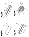
Fig. 12 in Vorderansicht gemäß Pfeil XIII inFig. 12 ; - Fig. 14
- eine weitere Ausführungsvariante einer Blockierhülse in perspektivischer Schrägansicht;
- Fig. 15
- eine weitere Ausführungsvariante einer Blockierhülse in perspektivischer Schrägansicht;
- Fig. 16
- die an einer Lenkspindel angeordnete Blockierhülse nach
Fig. 15 und ein Sperrglied der Lenkungsanlage im Längsschnitt; - Fig. 17
- eine erste Ausführungsvariante einer Anordnung von im Lagerabschnitt angebrachten Schmiertaschen einer teilweise dargestellten Blockierhülse;
- Fig. 18
- eine zweite Ausführungsvariante einer Anordnung von im Lagerabschnitt angebrachten Schmiertaschen einer teilweise dargestellten Blockierhülse;
- Fig. 19
- eine dritte Ausführungsvariante einer Anordnung von im Lagerabschnitt angebrachten Schmiertaschen einer teilweise dargestellten Blockierhülse;
- Fig. 20
- eine vierte Ausführungsvariante einer Anordnung von im Lagerabschnitt angebrachten Schmiertaschen einer teilweise dargestellten Blockierhülse;
- Fig. 21
- eine fünfte Ausführungsvariante einer Anordnung von im Lagerabschnitt angebrachten Schmiertaschen einer teilweise dargestellten Blockierhülse;
- Fig. 22
- eine Ausführungsvariante einer Anordnung einer im Lagerabschnitt angebrachten, an sich bekannten gleitfähigen Struktur einer teilweise dargestellten Blockierhülse;
- Fig. 23
- die Blockierhülse mit der an sich bekannten gleitfähigen Struktur geschnitten nach der Linie XXIII-XXIII in
Fig. 22 ; - Fig. 24
bis 27 - jeweils ein Verfahrenschritt eines möglichen Verfahrensablaufs zur Herstellung einer Blockierhülse;
- Fig. 25a bis 25d
- jeweils ein Verfahrenschritt eines möglichen Verfahrensablaufs zur Herstellung von Rastausnehmungen bzw. Schmiertaschen an einem Zuschritt;
- Fig. 26a und 26b
- jeweils ein Verfahrenschritt eines möglichen Verfahrensablaufs zur Herstellung eines Hohlprofiles aus einem platinenartigen Zuschnitt;
- Fig. 28
bis 31 - jeweils ein Verfahrensschritt einer zweiten Möglichkeit eines Verfahrensablaufs zur Herstellung einer weiteren Ausführungsvariante einer Blockierhülse;
- Fig. 29a bis 29c
- jeweils ein Verfahrenschritt eines möglichen Verfahrensablaufs zur Herstellung von Rastausnehmungen in einem Zuschnitt;
- Fig. 32
bis 34 - jeweils einen Verfahrensschritt einer dritten Möglichkeit eines Verfahrensablaufs zur Herstellung einer weiteren Ausführungsvariante einer Blockierhülse;
- Fig. 35
bis 38 - jeweils einen Verfahrensschritt einer vierten Möglichkeit eines Verfahrensablaufs zur Herstellung einer weiteren Ausführungsvariante einer Blockierhülse.
- Fig. 1
- a blocking sleeve according to the invention in a perspective oblique view;
- Fig. 2
- the blocking sleeve after
Fig. 1 cut according to the lines II-II; - Fig. 3
- the blocking sleeve after
Fig. 1 in longitudinal section; - Fig. 4
- a further embodiment of a blocking sleeve according to the invention in a perspective oblique view;
- Fig. 5
- the blocking sleeve after
Fig. 4 in longitudinal section; - Fig. 6
- the blocking sleeve after
Fig. 4 in cross-section; - Fig. 7
- a further embodiment of the attached to a steering shaft blocking sleeve in longitudinal section;
- Fig. 8
- a further embodiment of the attached to the steering shaft blocking sleeve in longitudinal section;
- Fig. 9
- a further embodiment of a mounted on a steering shaft blocking sleeve in cross section and half-sectional view about a horizontal axis of symmetry;
- Fig. 10
- the blocking sleeve after
Fig. 9 in longitudinal section; - Fig. 11
- a possible embodiment of a steering shaft with mounted on this blocking sleeve in longitudinal section;
- Fig. 12
- a further embodiment of a blocking sleeve in perspective oblique view;
- Fig. 13
- the blocking sleeve after
Fig. 12 in front view according to arrow XIII inFig. 12 ; - Fig. 14
- a further embodiment of a blocking sleeve in perspective oblique view;
- Fig. 15
- a further embodiment of a blocking sleeve in perspective oblique view;
- Fig. 16
- the arranged on a steering shaft locking sleeve after
Fig. 15 and a locking member of the steering system in longitudinal section; - Fig. 17
- a first embodiment of an arrangement of mounted in the bearing portion lubrication pockets of a partially illustrated blocking sleeve;
- Fig. 18
- a second embodiment of an arrangement of mounted in the bearing portion lubricating pockets of a partially illustrated blocking sleeve;
- Fig. 19
- a third embodiment of an arrangement of mounted in the bearing portion lubricating pockets of a partially illustrated blocking sleeve;
- Fig. 20
- a fourth embodiment of an arrangement of mounted in the bearing portion lubricating pockets of a partially illustrated blocking sleeve;
- Fig. 21
- a fifth embodiment of an arrangement of mounted in the bearing portion lubricating pockets of a partially illustrated blocking sleeve;
- Fig. 22
- a variant of an arrangement of a mounted in the bearing portion, known per se slidable structure of a partially illustrated blocking sleeve;
- Fig. 23
- the blocking sleeve with the known sliding structure cut according to the line XXIII-XXIII in
Fig. 22 ; - Fig. 24 to 27
- in each case a method step of a possible method sequence for producing a blocking sleeve;
- Fig. 25a to 25d
- in each case a method step of a possible procedure for the production of recesses or lubrication pockets at a Zuschritt;
- Figs. 26a and 26b
- in each case a method step of a possible method sequence for producing a hollow profile from a blank-like blank;
- Fig. 28 to 31
- in each case a method step of a second possibility of a method sequence for producing a further embodiment variant of a blocking sleeve;
- Fig. 29a to 29c
- in each case a method step of a possible method sequence for the production of latching recesses in a blank;
- FIGS. 32 to 34
- in each case a method step of a third possibility of a method sequence for producing a further embodiment variant of a blocking sleeve;
- FIGS. 35 to 38
- in each case a method step of a fourth possibility of a method sequence for producing a further embodiment variant of a blocking sleeve.
Einführend sei festgehalten, dass in den unterschiedlich beschriebenen Ausführungsformen gleiche Teile mit gleichen Bezugszeichen bzw. gleichen Bauteilbezeichnungen versehen werden, wobei die in der gesamten Beschreibung enthaltenen Offenbarungen sinngemäß auf gleiche Teile mit gleichen Bezugszeichen bzw. gleichen Bauteilbezeichnungen übertragen werden können. Auch sind die in der Beschreibung gewählten Lageangaben, wie z.B. oben, unten, seitlich usw. auf die unmittelbar beschriebene sowie dargestellte Figur bezogen und sind bei einer Lageänderung sinngemäß auf die neue Lage zu übertragen.By way of introduction, it should be noted that in the differently described embodiments, the same parts are provided with the same reference numerals or the same component names, wherein the disclosures contained in the entire description can be mutatis mutandis to the same parts with the same reference numerals or component names. Also, the location information chosen in the description, such as top, bottom, side, etc. related to the immediately described and illustrated figure and are to be transferred to the new situation mutatis mutandis when a change in position.
In den
Die Blockierhülse 1 bzw. der Hülsenkörper 4 ist im gefertigten Zustand im Querschnitt hohlprofilartig ausgebildet, wobei an einer Innenseite 7 des Hülsenkörpers 4 sich entlang einer Längsmittelachse 8 eine Durchgangsöffnung 9 erstreckt. Die Durchgangsöffnung 9 wird in zumindest einem Lagerabschnitt 10, der sich zumindest über einen Teil einer Hülsenlänge 11 erstreckt, von einer Stützfläche 12 begrenzt. Eine Umfangskontur 13 der Stützfläche 12 ist entsprechend einer Umfangskontur 14 an einer Außenoberfläche 15 der Lenkspindel 2 gebildet, wobei die Umfangskonturen 13, 14 vorzugsweise kreisförmig verlaufen. Der Lagerabschnitt 10 bildet somit vorzugsweise einen ringförmigen und zylindrischen Bereich des Hülsenkörpers 4 aus. Es ist jedoch auch eine mehreckige, insbesondere rechteckige, Ausgestaltung des hohlprofilartigen Querschnitts der Blockierhülse 1 möglich, wobei der Lagerabschnitt 10 mit der Stützfläche 12 einer beliebigen Konturform, insbesondere einer Kontur eines Außenumfangs der Lenkspindel 2, entsprechen kann und/oder im Teilabschnitt der Hülsenlänge 11 außerhalb der Lagerabschnitte 10 die Blockierhülse 1 unabhängig von der Querschnittsform in den Lagerabschnitten 10 oder dieser entsprechend als eckiger, z.B. quadratischer oder dreieckiger, Hohlquerschnitt gebildet sein kann.The blocking
Im in
Wie in
Die Rastausnehmungen 5 an der Außenseite 6 des Hülsenkörpers 4 sind mit einem Sperrglied 21 der Lenkungsanlage 3 in Eingriff bringbar, wobei das Sperrglied 21 in eine Freigabe- oder Sperrstellung überführbar ist. Das Sperrglied 21 ist Bestandteil eines Lenkschlosses 22 der Lenkungsanlage 3, wobei das Sperrglied 21 gemäß dem dargestellten Doppelpfeil 23 verstellbar im Längsschloss 22 gelagert ist und eine Freigabestellung, bei der das Sperrglied 21 außer Eingriff mit den Rastausnehmungen 5 ist oder eine Sperrstellung, bei der das Sperrglied 21 in zumindest einer der Rastausnehmungen 5 eingreift, über das Lenkschloss 22 festgelegt wird. Auf den Aufbau des Lenkschlosses 22 wird an dieser Stelle nicht näher eingegangen, da der Aufbau und die Funktionsweise derartiger Sperr- bzw. Arretiervorrichtungen für Kraftfahrzeugslenkungsanlagen bereits aus dem Stand der Technik bekannt sind.The locking recesses 5 on the
Es sind nun die Stützflächen 12 in den Lagerabschnitten 10 mit vorzugsweise mehreren Schmiertaschen 24 versehen, die in den Stützflächen 12 vertieft angeordnet sind und die zur Aufnahme eines Schmierstoffes geeignet sind oder es ist die Stützfläche 12 an oder zwischen einer gleitfähigen Struktur (siehe
Die Rastausnehmungen 5 der in
Jeweils eine Rastausnehmung 5 ist somit zwischen zwei benachbarten Auskragungen 26 ausgebildet, wobei die Rastausnehmungen 5 von sich gegenüberliegenden Anschlagflächen 29a, 29b zweier Auskragungen 26 begrenzt werden, die jeweils an Längsseitenbereichen 30a, 30b der Auskragungen 26 angeordnet sind. Die Auskragungen 26 erstrecken sich in Längsrichtung entlang einer parallel zur Längsmittelachse 8 des Hülsenkörpers 4 verlaufenden Erstreckungsachse 31 über eine Länge 32. Eine Rastbreite 33 der Rastausnehmung 5, die zwischen den sich gegenüberliegenden Anschlagflächen 29a, 29b verläuft, wird bestimmt durch eine Breite 34 der Auskragungen 26 sowie der Anzahl der über den Umfang an der Außenseite 6 des Hülsenkörpers 4 angeordneten Auskragungen 26. Die Rastbreite 33 ist dabei so bemessen, dass das Sperrglied 21, insbesondere ein Sperrbolzen 35, in die Rastausnehmung 5 hineinragen kann und vorzugsweise spielfrei oder mit geringer Toleranz formschlüssig durch die Anschlagflächen 29a, 29b begrenzt wird, falls sich das Sperrglied 21 des Lenkschlosses 22 in Sperrstellung befindet. Der Sperrbolzen 35 weist hierzu insbesondere parallel zueinander liegende Arretierflächen 36a, 36b auf, die in dessen Sperrstellung an den Anschlagflächen 29a, 29b anliegen.In each case a latching
Die Auskragungen 26 weisen eine trapezförmige Querschnittsform bzw. Umfangskonturen auf, wobei die Anschlagflächen 29a, 29b an je einer Auskragung 26 hierzu in einem Winkel 37 zueinander stehen, der vorzugsweise spitz in Richtung der Innenseite 7 des Hülsenkörpers 4 zusammenläuft. Eine Radialachse 38, entlang der sich die Auskragungen über die Höhe 28 erstrecken, ist normal auf die Längsmittelachse 8 des Hülsenkörpers 4 gerichtet. Die Auskragungen 26 weisen je eine Deckfläche 39 auf, die normal bzw. schräg auf die Radialachse 38 steht und um die Höhe 28 von der umliegenden Oberfläche 27 distanziert ist, wobei sich die Anschlagflächen 29a, 29b der Auskragungen 26 von der Deckfläche 39 in Richtung der Radialachse 38 hin zur Durchgangsöffnung 9 entsprechend dem Winkel 37 zueinander verjüngend erstrecken. Die Anschlagflächen 29a, 29b an einer Auskragung 26 verlaufen in einem derartigen Winkel 37 zueinander, dass die über die Rastbreite 33 voneinander distanzierten und sich gegenüberliegenden Anschlagflächen 29a, 29b zweier benachbarter Auskragungen 26 parallel zueinander verlaufen. Eine derartige parallele Anordnung der Anschlagflächen 29a, 29b ermöglicht in vorteilhafter Weise die Verwendung von Sperrbolzen 35 mit parallelen Arretierflächen 36a, 36b, wie diese im Stand der Technik verwendet werden.The
Es sei angemerkt, dass die Auskragungen 26 auch weitere Querschnittsformen aufweisen können, beispielsweise können die Anschlagflächen 29a, 29b an einer Auskragung 26 parallel oder in einem Winkel 37, der sich hin zur Innenseite 7 des Hülsenkörpers 4 stumpf erweitert, verlaufen, wodurch die Auskragungen 26 rechteckige oder beliebige kegelstumpfartige Querschnittsformen aufweisen können.It should be noted that the
Die Rastausnehmung 5 ist im Querschnitt bei trapezförmigen Auskragungen 26 U-förmig bzw. wannenförmig ausgebildet, wobei wie vorstehend angemerkt diese auch eine kegelstumpf- bzw. trapezartige oder rechteckige Querschnittsform aufweisen kann. Es muss lediglich sichergestellt sein, dass das Sperrglied mit seinen Arretierflächen 36a, 36b spielfrei bzw. nahezu spielfrei an den Anschlagflächen 29a, 29b zur Anlage gebracht werden kann.The latching
Die Hülsenlänge 11 setzt sich somit aus den sich über die Länge 32 erstreckenden Auskragungen 26 und den zumindest einen Teil der restlichen Hülsenlänge 11 einnehmenden Lagerabschnitten 10 mit den Stützflächen 12 zusammen. Wie ausführungsgemäß dargestellt, ist innerhalb der Auskragungen 26 jeweils ein Hohlraum 40 angeordnet, der sich in Form einer Vertiefung 41 von der Innenseite 7 des Hohlkörpers 4 in Richtung dessen Außenseite 6 erstreckt, wobei die Vertiefung 41 an der Innenseite 7 nutartig bzw. wannenartig mit einer Innenfläche 42 verläuft. Eine innere Kontur der Vertiefung 41 an der Innenfläche 42 und die äußere Kontur der Auskragung 26 sind dabei bevorzugt gleichförmig ausgebildet, wobei die Auskragungen 26 beispielsweise die Form eines U- oder C-Profiles oder dergleichen aufweisen. Die Auskragungen 26 können somit einen Trapezhohlprofilquerschnitt aufweisen. Eine Wandstärke 43 des Hülsenkörpers 4 kann im Bereich der den Hohlraum 40 aufweisenden Auskragungen 26 und am restlichen Hülsenkörper 4 eine einheitliche Dimension aufweisen. Die Wandstärke 43 des Hülsenkörpers 4 beträgt beispielsweise zwischen 0,3 und 5 mm, insbesondere 0,5 bis 3 mm, bevorzugt 1 bis 2mm. In Abhängigkeit eines verwendeten Herstellungsverfahrens der hohlen Auskragungen 26 kann deren Wandstärke 43 gegenüber dem restlichen Hülsenkörper 4 insbesondere aufgrund von Materialstreckung geringer sein, beispielsweise kann die Wandstärke 43 der Auskragungen 26 zwischen 1/4 und 3/4, insbesondere zwischen 1/3 und 2/3 oder ca. im Bereich der Hälfte der Wandstärke 43 des restlichen Hülsenkörpers 4 liegen.The
Der Hülsenkörper 4 ist vorzugsweise aus einem einheitlichen Material, insbesondere aus Stahl, Aluminiurn oder aus einer geeigneten metallischen Legierung gebildet. Es ist möglich, dass der Hülsenkörper 4 durch ein z.B. mittels Druckumformen, insbesondere Strangpressen, hergestelltes, fugenloses Rohrprofil gebildet ist, in das die entsprechenden Rastausnehmungen 5 angebracht werden. Vorzugsweise ist der Hülsenkörper 4 jedoch aus einem umgeformten, platinenartigen Zuschnitt gebildet, der in eine hohlprofilartige Form gebracht wird und mittels einem Verbindungselement 44, das in einer Trennfuge 45 zwischen zwei Längsseitenkanten 46 und 47 angebracht wird, zu einem geschlossenen Hohlprofil verbunden wird, wie dies an späterer Stelle näher beschrieben wird.The
In den
Die Rastausnehmungen 5 weisen gemäß dem gezeigten Ausführungsbeispiel Ausschnitte 48 auf, die einen in der Durchgangsöffnung 9 liegenden Innenraum des Hülsenkörpers 4 nach außen hin freigeben. Die Ausschnitte 48 sind als über die gesamte Wandstärke 43 des Hülsenkörpers 4 verlaufende Materialdurchbrüche, die beispielsweise langlochartig rechteckiger oder ovaler Form entlang der Erstreckungsachse 31 längsverlaufen, gebildet.The locking recesses 5, according to the embodiment shown on
Wie dargestellt, sind die Rastausnehmungen 5 durch Umlaufstege 49 umschlossen, die sich über ein Ausmaß 50 in radialer bzw. schräger Richtung auf die Längsmittelachse 8 entlang der Radialachse 38 des Hohlkörpers 4 hin zum Innenraum des Hülsenkörpers 4 erstrecken. Eine den Ausschnitt 48 begrenzende Umfangskante 51 ist vorzugsweise über deren Umfang geschlossen und insbesondere oval, ringförmig, rechteckförmig oder dgl. ausgebildet, sodass die Rastausnehmung 5 längsschlitzartig im Hülsenkörper 4 verläuft.As shown, the latching recesses 5 are enclosed by
Der hohlprofilartige Hülsenkörper 4 weist über einen Teilabschnitt 52 der Hülsenlänge 11 eine bevorzugt vollumfängliche Aufweitung 53 bzw. Ausbauchung auf. Bei einem zylindrischen Hülsenkörper 4 ist ein Durchmesser 54 der Aufweitung 53 größer gegenüber einem Durchmesser 55 an den außerhalb des Teilabschnitts 52 liegenden Bereichen, wobei bei nicht-zylindrischer Aufweitung 53 die Linearabmaße dementsprechend ausgebildet sind. Die gegenüber der Aufweitung 53 radial zur Längsmittelachse 8 zurückgesetzten Bereiche sind zumindest teilweise durch die Lagerabschnitte 10 gebildet, die am Hülsenkörper 4 innenseitig die Stützflächen 12 zur reibschlüssigen Aufnahme der Lenkspindel 2 aufweisen. Die Ausschnitte 48 sind im Teilabschnitt 52 in einer um den Umfang des Hülsenkörpers 4 verlaufenden Reihe angeordnet, wobei die Erstreckungsachse 31, entlang derer sich die langlochartigen Rastausnehmungen 5 erstrecken, bevorzugt parallel zur Längsmittelachse 8 des Hülsenkörpers 4 verlaufen.The hollow profile-
Am Hülsenkörper 4 innenseitig liegende Stirnflächen 56 der Umlaufstege 49 sind vorzugsweise derartig ausgebildet, dass sich die durch die Durchgangsöffnung 9 verlaufende Lenkspindel 2 an diesen abstützt oder ein geringfügiger Spalt zwischen der Außenoberfläche 15 der Lenkspindel 2 und den Stirnflächen 56 ausgebildet wird. Die Stirnflächen 56 werden daher bevorzugt durch einen Hüllkörper 57, insbesondere eines Hüllzylinder, begrenzt, der die Umfangskontur 14 der Lenkspindel 2 im Bereich der Aufweitung 53 aufweist. Die Stirnflächen 56 sind somit jeweils entlang des Umfangs des Hüllkörpers 57 verlaufend ausgebildet. Von Vorteil ist nun eine Ausgestaltung, bei der Hüllkörperdurchmesser 58 dem Innendurchmesser 59 im Bereich der Lagerabschnitte 10 entspricht oder geringfügig größer ist als der Innendurchmesser 59, sodass eine durch die Durchgangsöffnung 9 ragende Lenkspindel 2 im Teilabschnitt 52 an deren Außenoberfläche 15 durch die Stirnflächen 56 gestützt wird. Die der Außenoberfläche 15 der Lenkspindel 2 zugewandten Stirnflächen 56 können somit einen Ausschlag bzw. ein Auslenken der Lenkspindel 2 aus einer zur Längsmittelachse 8 parallelen Normalposition begrenzen.On the
In die längsschlitzartigen Rastausnehmungen 5 kann in auf der Lenkspindel 2 montiertem Zustand der Blockierhülse 1 wiederum ein Sperrglied 21 eines Lenkschlosses 22 eingreifen, wobei somit eine Positionierung der Lenkspindel 2 gegenüber Verdrehung derselben erfolgt. Hierzu können Arretierflächen 36a, 36b an dem als Sperrbolzen 35 gebildeten Sperrglied 21 zumindest über Teilbereiche an der Anschlagfläche 29 flächig anliegen, oder nur mit der Umfangskante 51 des Ausschnitts 48 über einen Teilumfang oder vollumfänglich in Kontakt stehen. Sich gegenüberliegende Anschlagflächen 29a, 29b der schlitzförmigen Rastausnehmungen 5 können, wie dargestellt, beispielsweise in Richtung des Innenraums des Hülsenkörpers 4 entsprechend dem Winkel 37 spitz- oder stumpfwinkelig zueinander verlaufend bzw. verjüngend angeordnet sein oder parallel zueinander verlaufen.In the longitudinal slot-
Im Allgemeinen wird durch Ausformen von Umlaufstegen 49 die Anschlagfläche 29a, 29b gegenüber der sich ansonsten lediglich über die Wandstärke 43 erstreckenden Fläche vergrößert, sodass die Flächenpressung zwischen dieser und den Arretierflächen 36a, 36b des Sperrbolzens verringert werden kann und eine Versteifung der schlitzartigen Rastausnehmung 5 erreicht wird. Zweckmäßigerweise werden die Umlaufstege 49 durch Umformen der um die Ausschnitte 48 liegenden Bereiche ausgeformt, wobei dies spanlos durch aufweiten bzw. stauchen dieser Bereiche in Richtung des Innenraums des Hülsenkörpers 4 erfolgt.In general, the
In der
Die Lenkspindel 2 weist im dargestellten Ausführungsbeispiel einen ersten Spindeldurchmesser 60a und einen weiteren Spindeldurchmesser 60b auf, wobei der größere Spindeldurchmesser 60b durch einen Absatz 61 auf den geringen Spindeldurchmesser 60a radial in Richtung der Längsmittelachse 8 verjüngt wird. Der Hülsenkörper 4 liegt im Lagerabschnitt 10 mit dem Innendurchmesser 59a an der Lenkspindel 2 im Bereich des ersten, geringeren Durchmessers 60a mit der Klemmspannung an, und es erstreckt sich der restliche Hülsenkörper 4 in Richtung der Längsmittelachse 8 über den Absatz 61 der Lenkspindel 2 hinweg auf den weiteren, größeren Spindeldurchmesser 60b über einen Überlappungsbereich 63. Die Befestigung der Blockierhülse 1 an der Lenkspindel 2 erfolgt dabei bevorzugt ausschließlich über den Lagerabschnitt 10. In der gegenüber dem Innendurchmesser 59a im Lagerabschnitt 10 über einen Absatz 62 ausgebildeten, über den Teilabschnitt 52 verlaufenden Aufweitung 53 am Hülsenkörper 4 sind die Rastausnehmungen 5 angebracht. Der hohlprofilartige Hülsenkörper 4 verläuft über den Teilabschnitt 52 im Wesentlichen zylindrisch, wobei auch mehreckige Querschnittsformen des Hülsenkörpers 4 im Teilabschnitt 52 möglich sind. Im Allgemeinen sind der bzw. die Lagerabschnitte 10 gegenüber dem restlichen Teilabschnitt 52 mit der Aufweitung 53 als umlaufende, ringartige Bünde ausgebildet.The steering
Mit einer in
In der
In den
Die Umlaufstege 49 erstrecken sich in von Innenraum bzw. der Durchgangsöffnung 9 des Hülsenkörpers 4 abgewandter Richtung im Wesentlichen parallel zum Verlauf auf die normal zur Längsmittelachse 8 verlaufende Radialachse 38. Die Stirnfläche 56 sowie die Umfangskante 51 sind somit um das Ausmaß 50 gegenüber der umliegenden Außenoberfläche 27 des Hülsenkörpers 4 distanziert. Die den Ausschnitt 48 begrenzende Anschlagfläche 29 verläuft vorzugsweise parallel zur Radialachse 38. Die restlichen Bereiche am Hülsenkörper 4 außerhalb des Umlaufstegs 49 weisen eine ebenflächige, insbesondere zylindrische, äußere Oberfläche 27 auf.The
Außerhalb eines Teilabschnitts 64 der Hülsenlänge 11, in der entlang der Längsmittelachse 8 verlaufend der Umlaufsteg 49 mit der innenliegenden Rastausnehmung 5 angeordnet ist, können die Lagerabschnitte 10, mit der innenliegenden Stützfläche 12 ausgebildet sein.Outside a
An über den Umfang des hohlprofilartigen Hülsenkörpers 4 jeweils zwischen zwei benachbarten Umlaufstegen 49 bzw. der Rastausnehmungen 5 liegenden Zwischenbereichen 65 ist jeweils zumindest eine Laufnase 66 angeordnet. Die äußere Scheitelfläche 67 der Laufnase 66 liegt im Wesentlichen auf einem, die Seitenkanten der Stirnflächen 56 der Umlaufstege 49 tangierenden Hüllkreis 68, wobei der Hüllkreis 68 konzentrisch zur Längsmittelachse 8 des Hülsenkörpers 4 verläuft. Eine Nasenbreite 69 ist so bemessen, dass Breiten 70, 71 von neben jeder Laufnase 66 liegenden Zwischenräumen 72, 73 im Zwischenbereich 65 geringer sind, als eine Sperrbolzenbreite 73 des Sperrbolzens 35, die zwischen den Arretierflächen 36a, 36b verläuft. Ein unerwünschtes Einrasten des Sperrbolzens 35 im Zwischenbereich 65 zwischen zwei benachbarten Umlaufstegen 49 kann somit verhindert werden.At over the circumference of the hollow profile-
Es sei an dieser Stelle angemerkt, dass es selbstverständlich möglich ist, im Zwischenbereich 65 Zwischenräume 71; 72 vorzusehen, deren Breiten 71; 72 zumindest der Sperrbolzenbreite 73 entsprechen, um zusätzliche Rastpositionen am Umfang des Hülsenkörpers 4 zu schaffen. Ebenso ist es möglich, Anordnungen zur Verstärkung der Umlaufstege 49 vorzusehen, wie beispielsweise in strichlierten Linien 44 durch innenseitig an der Anschlagfläche 29 des Umlaufstegs 49 angebrachte Sicken 74 dargestellt.It should be noted at this point that it is of course possible in the
Ein weiteres, mögliches Ausführungsbeispiel einer Lenkungsanlage 3 mit der Lenkspindel 2 sowie der auf dieser befestigen Blockierhülse 1 ist in
In den
Im gezeigten Ausführungsbeispiel ist jedoch ein Teilungswinkel 80, um den die nebeneinander liegenden, leistenartigen Auskragungen 26 am Außenumfang bzw. der Oberfläche 27 des Hülsenkörpers 4 voneinander distanziert sind, geringer, sodass eine weitaus größere Anzahl von Auskragungen 26 um den Umfang der Außenseite 6 des Hülsenkörpers 4 angeordnet ist. Gemäß der in
Das als Sperrbolzen 35 ausgebildete Sperrglied 21 des Lenkschlosses 22 der Lenkungsanlage 3 ist in Sperrstellung zum gleichzeitigen Eingriff in mehrere Rastausnehmungen 5 ausgebildet. Hierzu weist der Sperrbolzen 35 mehrere Rastzähne 81 auf, die in Sperrstellung in die Rastausnehmung 5 ragen. Jeder Rastzahn 81 weist zwei Arretierflächen 36a, 36b auf, die mit den jeweiligen die Rastausnehmung 5 begrenzenden Anschlagflächen 29a, 29b in Kontakt treten. Bei der gezeigten Ausführungsvariante ist die hohe Anzahl von Auskragungen 26 und der Eingriff in die Rastausnehmungen 5 durch mehrere Rastzähne 81 von Vorteil, da eine Reduktion der Höhe 28 der Auskragungen 26 und der Aufteilung der Abstützkraft, die proportional zu einem über Lenkspindel 2 übertragenen Drehmoment ist, auf Anschlagflächen 29a, 29b mehrerer Auskragungen ermöglicht wird. Hierzu sind die Auskragungen 26 bzw. die Rastausnehmungen 5 an der Außenseite 6 des Hülsenkörpers 4 beispielsweise in Art eines keilwellenartigen oder kerbzahnartigen Profils ausgebildet. Gegenüber einer Rastprofilierung mit beispielsweise sechs oder acht zwischen den Auskragungen 26 liegenden Rastausnehmungen 5 kann die Höhe 28 der Auskragungen 26 somit auf die Hälfte, insbesondere ein Drittel, bevorzugt ein Viertel reduziert werden. Somit ist bei Sperrstellung des Sperrbolzens 35 nur ein geringer Verdrehwinkel der Lenkspindel 2 zum Einrasten in die Rastausnehmungen 5 notwendig, wodurch der Handhabung- bzw. Bedienkomfort einer Lenkungsanlage 3 verbessert wird. Weiters lässt sich die Herstellung der Auskragungen 26 der Rastprofilierung vereinfachen, wie dies an späterer Stelle im Zuge der
Eine weitere Ausführungsvariante einer Blockierhülse 1 ist in
Durch die in
Eine weitere Ausführungsvariante einer Blockierhülse 1 bzw. Lenkungsanlage 3 ist in den
Das in
In
Zu den in den
Das Verbindungselement 44 ist vorzugsweise durch eine Schweißnaht gebildet, wobei hierzu insbesondere eine Laser- oder Plasmaschweißnaht aufgrund des verzugsarmen Verbindungsvorganges verwendet werden kann. Das Verbindungselement kann weiters durch eine Klebeschicht, eine Lötverbindung oder dgl. gebildet sein, wobei derartige Verbindungsverfahren aus dem Stand der Technik bekannt sind.The connecting
Zum Hülsenkörper 4 sei im Allgemeinen angemerkt, dass dieser aus nur einem einzigen Fügeteil bestehen kann, wie dies in den Fig. dargestellt ist, wobei dieser eine hohlprofilartige Form, insbesondere eine zumindest teilweise zylindrische oder ringförmige Form aufweist und im Verbindungsbereich 82 die Trennfuge 45 über die Hülsenlänge 11 durchgehend verläuft. Es ist jedoch auch möglich, dass der Hülsenkörper 4 aus mehreren, miteinander in Verbindungsbereichen 82 zu einem geschlossenen Hohlprofil verbunden Fügeteilen gebildet ist. Jeder Fügeteil ist dabei an zwei Verbindungsbereichen 82 über ein Verbindungselement 44 mit dem benachbarten Fügeteilen unlösbar verbunden.The
In den
Im Allgemeinen sei zum Lagerabschnitt 10 angemerkt, dass dieser innenseitig im Bereich der Durchgangsöffnung 9 die Stützfläche 12 aufweist, die an der Außenoberfläche 15 der Lenkspindel 2 reibschlüssig befestigt bzw. befestigbar ist, wie dies vorstehend bereits beschrieben wurde. Der Reibschluss zwischen der Stützfläche 12 und der Außenoberfläche 15 wird dadurch erreicht, dass der Hülsenkörper 4 im Lagerabschnitt 12 mit einer Klemmspannung an der Lenkspindel 2 angebracht ist. Dabei ist es möglich, dass diese Klemmspannung durch Verformung mindestens eines der beiden aneinanderliegenden Teile, also Hülsenkörper 4 oder Lenkspindel 2, im Bereich des Lagerabschnitts 10 erzeugt wird, sodass im verformten Teil eine innere Spannung, insbesondere Zugspannung, hervorgerufen wird. Es ist beispielsweise möglich die Klemmspannung durch Aufweiten der gegenüber der Stützfläche 12 innenliegenden Lenkspindel 2 oder ein Aufschrumpfen des Lagerabschnitts 10 des Hülsenkörpers 4 auf die Außenoberfläche 15 der Lenkspindel 2 herzustellen.In general, it should be noted to the bearing
In einer bevorzugten Ausführungsvariante erfolgt die Erzeugung der Klemmspannung jedoch durch plastische Verformung des Lagerabschnitts 10 des Hülsenkörpers 4 in auf die Längsmittelachse 8 des Hülsenkörpers 4 normaler Richtung, wobei die Lenkspindel 2 mit der Außenoberfläche 15 in ihrer Form unverändert bleibt. Hierzu ist der Innendurchmesser 59a im Lagerabschnitt 10 am Hülsenkörper 4 in dessen Urform, d.h. im nicht plastisch aufgeweiteten Zustand, zumindest geringfügig kleiner bemessen als ein Spindeldurchmesser 60a der Lenkspindel 2. Die Urform des Lagerabschnitts 10 der Blockierhülse 1 beschreibt jene Form, in der die Blockierhülse 1 als gefertigter, loser Einzelteil vorliegt und noch nicht auf die Lenkspindel 2 aufgebracht bzw. aufgeschoben wurde.In a preferred embodiment, however, the generation of the clamping voltage is effected by plastic deformation of the bearing
Bei Aufschieben der Blockierhülse 1 auf die Lenkspindel 2 folgt nun in zumindest den Bereichen, in denen eine reibschlüssige Verbindung zwischen der Stützfläche 12 und Außenoberfläche 15 ausgebildet werden soll, eine Verformung des Lagerabschnitts 10 bis zur Überschreitung der Elastizitätsgrenze des Materials, aus dem der Lagerabschnitt 10 besteht. In Sperrstellung des Sperrglieds 21 - also bei arretierter Blockierhülse 1 und somit gegen Verdrehung feststehender Lenkspindel 2 - wird bei Verdrehen eines Lenkrades über die Lenkspindel 2 ein Drehmoment erzeugt, welchem ein gleich großes Drehmoment über den Sperrwiderstand an des in die Rastausnehmung 5 der Blockierhülse 1 eingreifenden Sperrglieds 21 entgegen wirkt. Die Verbindungsfestigkeit des Reibschlusses zwischen der an die Außenoberfläche 15 der Lenkspindel 2 angepressten Stützfläche 12 im Lagerabschnitt 10 der Blockierhülse 1 ist derart bemessen, dass sich der Reibschluss bei Übersteigen eines der maximalen Reibkraft entsprechenden Grenzdrehmomentwertes löst und die Lenkspindel 2 in der Verbindung durchrutscht. Die Verbindungsfestigkeit und der Grenzdrehmomentwert der reibschlüssigen Verbindung wird durch den Haftreibungskoeffizienten, sowie die effektive Kontaktfläche dieser Verbindung, welche durch die Auflagebreite 20, den Innendurchmesser 59a sowie den Flächenanteil der in der Stützfläche 12 vertieften Schmiertaschen 24 bestimmt ist, bestimmt. Dieser Grenzdrehmomentwert liegt beispielsweise im Bereich von 50 bis 300 Nm, insbesondere ca. 100 bis 200 Nm.When pushing the blocking
Es sei zum Innendurchmesser 59a des Lagerabschnitts 10 der Blockierhülse 1 angemerkt, dass dieser in der Urform gegenüber dem Spindeldurchmesser 60a, 60b der Lenkspindel 2 ein Untermaß von beispielsweise 0,1 bis 1 mm, insbesondere 0,2 bis 0,7 mm, bevorzugt 0,3 mm bis 0,5 mm aufweist, sodass bei Aufziehen oder Aufschieben der Blockierhülse 1 auf die Lenkspindel 2 eine plastische Verformung des Lagerabschnitts 10 in radialer Richtung auf dessen Längsmittelachse 8 erfolgt.It should be noted to the
Um nun ein Aufschieben oder Aufziehen der Blockierhülse 1 auf die Lenkspindel 2 zu ermöglichen, ohne dass an der Stützfläche 12 des Lagerabschnitts 10 oder der Außenoberfläche 15 der Lenkspindel 2 ein wesentlicher Materialabrieb bzw. Fressen von Material erfolgt, sind an der Stützfläche 12 vorzugsweise mehrere der Schmiertaschen 24 vertieft angeordnet oder es ist die an sich bekannte gleitfähige Struktur 89 mit der Stützfläche 12 innenseitig am Hülsenkörper 4 vorgesehen. Diese Schmiertaschen 24 sind jeweils zur Aufnahme eines Schmierstoffes geeignet, wobei als Schmierstoffe reibungsmindernde Schmieröle, Schmierfette oder Festschmierstoffe verwendet werden können, insbesondere synthetische Hochleistungshaftschmierstoffe. Durch die in den Schmiertaschen 24 angeordneten Schmierstoffe erfolgt beim Aufschieben der Blockierhülse 1 auf die Lenkspindel 2 ein Benetzen der aneinander liegenden Stützfläche 12 und Außenoberfläche 15, wodurch die Gleiteigenschaften verbessert werden bzw. beim Aufschiebevorgang der Reibungskoeffizient zwischen der Stützfläche 12 und der Außenoberfläche 15 herabgesetzt wird. Ein ungewollter Materialabrieb, welcher eine Beschädigung der Kontaktflächen durch Bildung von Riefen oder dergleichen zur Folge hat kann verhindert werden und die Verbindungsfestigkeit der reibschlüssigen Verbindung in Montageposition der Blockierhülse 1 an der Lenkspindel 2 kann im Wesentlichen vorbestimmt und reproduziert werden.In order to enable sliding or mounting of the blocking
Mögliche Ausführungsbeispiele für die Anordnung der Schmiertaschen 24 in der Stützfläche 12 im Lagerabschnitt 10 sind in den
Die Schmiertaschen 24 können an der Umfangskontur 13 der Stützfläche 12 gleichmäßig bzw. symmetrisch verteilt angeordnet sein, wobei jeweils zueinander benachbarte Schmiertaschen denselben Abstand 78 voneinander distanziert sind. Selbstverständlich ist auch eine ungleichmäßige bzw. unsymmetrische Verteilung der Schmiertaschen 24 in der Umfangskontur 13 der Stützfläche 12 möglich. Weiters ist es möglich, dass im Falle von zwei Lagerabschnitten 10 am Hülsenkörper 4, die jeweils in einem der Endbereiche 16, 17 angeordnet sind, die Schmiertaschen 24 in den Stützflächen 12 jeweils gleichartig zueinander verlaufen, oder die Schmiertaschen 24 in den Stützflächen 12 unterschiedlich zueinander verlaufen, insbesondere gegengleich oder spiegelverkehrt zueinander in der Stützfläche 12 angeordnet sind.The lubrication pockets 24 may be arranged distributed uniformly or symmetrically on the
Bei der in
Es besteht weiters die Möglichkeit, dass die Schmiertaschen 24 in der Stützfläche 12 in Form von Mikrostrukturen, beispielsweise unregelmäßige, sehr kleine Vertiefungen, ausgebildet sind. Eine weitere Möglichkeit besteht darin, dass die Schmiertaschen 24 in der eben ausgebildeten Stützfläche 12 durch zwischen Profilkuppen liegende Profiltäler des wirklichen Profils der Stützfläche 12 gebildet sind, wobei das wirkliche Profil bzw. Oberflächen- Rauhigkeitsprofil eine mittlere Rautiefe von 0,2 bis 200 µm aufweist.There is also the possibility that the lubrication pockets 24 in the
In den
Die gleitfähige Struktur 89 kann durch eine flächig auf den Hülsenkörper 4 aufgebrachte Beschichtung, insbesondere eine Blechbeschichtung oder dergleichen, gebildet sein bzw. bei der Herstellung an der Innenseite 7 des Hülsenkörpers 4 im Lagerabschnitt 10 flächig aufgetragen werden. Das Material der Beschichtung ist derart ausgewählt, dass eine die aneinanderliegende Werkstoffpaarung zwischen Lenkspindel 2 und Blockierhülse 1 einen geringen Reibungskoeffizienten ausbildet. Nach einer anderen Ausführung kann eine gleitfähige Struktur 89 an der Innenseite 7 des Hülsenkörpers 4 vorgesehen sein, die durch ein Oberflächenveredelungsverfahren, beispielsweise thermisch oder chemisch Härten, Phosphatieren, Nitrieren, erzeugt wird, sodass die gleitfähige Struktur 89 eine veredelte Stützfläche 12 bildet.The
Es besteht weiters die Möglichkeit, dass die Lenkspindel 2 eine Beschichtung oder behandelte Oberfläche aufweist, beispielsweise dass die Lenkspindel 2 eine im Zusammenwirken mit der Blockierhülse 1 reibungsmindemde Gleitschicht mit der Außenoberfläche 15 im Aufschiebeabschnitt für die Blockierhülse 1 aufweist und/oder die Lenkspindel 2 im Bereich einer Befestigungsstelle der Blockierhülse 1 eine im Zusammenwirken mit der Blockierhülse 1 reibungserhöhende Reibschicht aufweist.There is also the possibility that the
Es ist anzumerken, dass eine der in den
Eine eigenständige Lösung der Aufgabe der Erfindung betrifft die Lenkungsanlage 3 eines Kraftfahrzeuges, die das Lenkschloss 22 mit dem in Freigabe oder Sperrstellung überführbaren Sperrglied 21 und die Lenkspindel 2 mit dem auf dieser angeordneten Blockierhülse 1 umfasst. Wie vorstehend beschrieben, ist die Blockierhülse 1 dabei mit einer Klemmspannung zur Herstellung einer reibschlüssigen Verbindung im Lagerabschnitt 10 der Blockierhülse 1 an der Lenkspindel 2 angebracht, wobei das Sperrglied 21 in Sperrstellung einer der Rastausnehmungen 5 der Blockierhülse 1 bevorzugt formflüssig in Eingriff steht. Somit blockiert in Sperrstellung des Sperrglieds 21 die Lenkspindel 2 und ist gegen Verdrehung gesichert, wobei bei Auftreten eines Drehmomentes an der Lenkspindel 2, das den Grenzdrehmomentwert übersteigt, sich der Reibschluss zwischen Lenkspindel 2 und Lagerabschnitt 10 des Hülsenkörpers 4 löst und die Lenkspindel 2 relativ zur Blockierhülse 1 in einer Verdrehbewegung nach dem Funktionsprinzip einer Rutschkupplung durchrutscht.An independent solution of the object of the invention relates to the
In den
In den
In
Dabei wird der platinenartige Zuschnitt 90 in einem ersten Umformschritt gemäß
Die Herstellung einer Wellenform gemäß Verfahrensschritt nach
Im Verfahrensschritt nach
In einem weiteren Verfahrensschritt nach
In einem weiteren, nicht dargestellten Verfahrensschritt kann nach der Herstellung der Schmiertaschen 24 in der Stützfläche 12 ein Einbringen bzw. Auftragen eines Schmierstoffes, insbesondere Schmieröls oder Schmierfetts oder Festschmierstoffs, durch Benetzen bzw. Befüllen der Schmiertaschen 24 mit diesem erfolgen.In a further process step, not shown, after the production of the lubricating pockets 24 in the
Im Verfahrensschritt nach
In einem weiteren Verfahrensschritt gemäß
Vor dem Anbringen des Verbindungselementes 44 in der Trennfuge 45 kann ein plastisches Aufweiten des Hülsenkörpers 4 im Bereich der Längsseitenkanten 46, 47 in radialer Richtung auf die Längsmittelachse 8 erfolgen, wobei der aufgeweitete Bereich beispielsweise um 0,1 bis 0,5 mm, insbesondere ca. 0,3mm, radial nach außen verformt wird. Wird nun das Verbindungselement 44 in der Trennfuge 45 angeordnet, kann es vorkommen, dass dieses radial nach innen über die Längsseitenkante 46, 47 in die Durchgangsöffnung 9 hineinragt, wobei dies insbesondere bei Schweißnähten - bedingt durch beim Schweißprozess in Richtung der Durchlassöffnung 9 ablaufender Schmelze - der Fall sein kann. Durch eine Umfangskontur 13 des Lagerabschnitts 10, die aufgrund des geringfügig aufgeweiteten Bereichs im Verbindungsbereich 82 nicht vollkommen zylindrisch bzw. zentrisch zur Längsmittelachse 8 verläuft, können diese vorspringenden Teile des Verbindungselements im zusätzlich gebildeten Zwischenraum an der Innenseite 7 des aufgeweiteten Bereichs aufgenommen werden, wodurch die Lenkspindel 2 in der Durchgangsöffnung 9 unbehindert verlaufen kann. Eine Nachbearbeitung im Verbindungsbereich 82, beispielsweise ein Abschleifen der Schweißnaht, ist somit vorteilhafter Weise nicht notwendig.Before attaching the connecting
Ein weiterer möglicher Verfahrensablauf zur Herstellung einer Blockierhülse 1 ist in den
In einem weiteren Verfahrensschritt nach
Im Verfahrensschritt nach
In den
Ein derartiger, profilierter Zuschnitt 90 kann in einem Verfahrensschritt gemäß
Die
Im weiteren Verfahrensschritt nach
Im Allgemeinen sei zur Herstellung der Blockierhülse 1 angemerkt, dass diese bevorzugt maschinell und automatisiert an einer entsprechenden Vorrichtung erfolgt.In general, for the production of the blocking
Der Ordnung halber sei abschließend darauf hingewiesen, dass zum besseren Verständnis des Aufbaus der Blockierhülse 1 und der Lenkungsanlage 3 diese bzw. deren Bestandteile teilweise unmaßstäblich und/oder vergrößert und/oder verkleinert dargestellt wurden.For the sake of order, it should finally be pointed out that in order to better understand the construction of the blocking
- 11
- Blockierhülseblocking sleeve
- 22
- Lenkspindelsteering shaft
- 33
- Lenkungsanlagesteering system
- 44
- Hülsenkörpersleeve body
- 55
- Rastausnehmungrecess
- 66
- Außenseiteoutside
- 77
- Innenseiteinside
- 88th
- LängsmittelachseLongitudinal central axis
- 99
- DurchgangsöffnungThrough opening
- 1010
- Lagerabschnittbearing portion
- 1111
- Hülsenlängesleeve length
- 1212
- Stützflächesupport surface
- 1313
- Umfangskonturperipheral contour
- 1414
- Umfangskonturperipheral contour
- 1515
- Außenoberflächeouter surface
- 1616
- Endbereichend
- 1717
- Endbereichend
- 1818
- Stirnkantefront edge
- 1919
- Stirnkantefront edge
- 2020
- AuflagebreiteSupport width
- 2121
- Sperrgliedlocking member
- 2222
- Lenkschlosssteering lock
- 2323
- Doppelpfeildouble arrow
- 2424
- Schmiertaschelubrication pocket
- 2525
- Begrenzungsflächeboundary surface
- 2626
- Auskragungenprojections
- 2727
- Oberflächesurface
- 2828
- Höheheight
- 29a29a
- Anschlagflächestop surface
- 29b29b
- Anschlagflächestop surface
- 30a30a
- LängsseitenbereichLongitudinal side region
- 30b30b
- LängsseitenbereichLongitudinal side region
- 3131
- Erstreckungsachseextension axis
- 3232
- Längelength
- 3333
- RastbreiteRest width
- 3434
- Breitewidth
- 3535
- Sperrbolzenlocking pin
- 3636
- Arretierflächelocking surface
- 36a36a
- Arretierflächelocking surface
- 3737
- Winkelangle
- 3838
- Radialachseradial axis
- 3939
- Deckflächecover surface
- 4040
- Hohlraumcavity
- 4141
- Vertiefungdeepening
- 4242
- Innenflächepalm
- 4343
- WandstärkeWall thickness
- 4444
- Verbindungselementconnecting element
- 4545
- Trennfugeparting line
- 4646
- LängsseitenkanteLongitudinal side edge
- 4747
- LängsseitenkanteLongitudinal side edge
- 4848
- Ausschnittneckline
- 4949
- Umlaufstegperipheral web
- 5050
- Ausmaßextent
- 5151
- Umfangskanteperipheral edge
- 5252
- Teilabschnittpart Of
- 5353
- Aufweitungwidening
- 5454
- Durchmesserdiameter
- 5555
- Durchmesserdiameter
- 5656
- Stirnflächeface
- 5757
- Hüllkörperenveloping body
- 5858
- HüllkörperdurchmesserHüllkörperdurchmesser
- 59a59a
- InnendurchmesserInner diameter
- 59b59b
- InnendurchmesserInner diameter
- 60a60a
- SpindeldurchmesserSpindle diameter
- 60b60b
- SpindeldurchmesserSpindle diameter
- 6161
- Absatzparagraph
- 6262
- Absatzparagraph
- 6363
- Überlappungsbereichoverlap area
- 6464
- Teilabschnittpart Of
- 6565
- Zwischenbereichintermediate area
- 6666
- Laufnaserunny nose
- 6767
- Scheitelflächeapex surface
- 6868
- Hüllkreisenveloping circle
- 6969
- Nasenbreitenose width
- 7070
- Breitewidth
- 7171
- Breitewidth
- 7272
- Zwischenraumgap
- 7373
- SperrbolzenbreiteLocking pin width
- 7474
- SickeBeading
- 7575
- Pfeilarrow
- 7676
- Winkelangle
- 7777
- Längsachselongitudinal axis
- 7878
- Abstanddistance
- 79a79a
- Schenkelleg
- 79b79b
- Schenkelleg
- 8080
- Teilungswinkelpitch angle
- 8181
- Rastzahnratchet
- 8282
- Verbindungsbereichconnecting area
- 8383
- Spaltbreitegap width
- 8484
- Zahnkranzsprocket
- 8585
- Zahntooth
- 8686
- Winkelangle
- 8787
- Pfeilarrow
- 8888
- Zahnkranzsprocket
- 8989
- Gleitfähige StrukturSlidable structure
- 9090
- Zuschnittcut
- 9191
- Blechteilsheet metal part
- 9292
- Zuschnittlängecutting length
- 9393
- Abstanddistance
- 9494
- Zuschnittbreitecutting width
- 9595
- LängsseitenkanteLongitudinal side edge
- 9696
- LängsseitenkanteLongitudinal side edge
- 9797
- MaterialdurchbruchMaterial Breakthrough
- 9898
- Profilierungprofiling
Claims (9)
- Blocking sleeve (1) for a steering spindle (2) of a steering system (3) of a motor vehicle, which forms a sleeve body (4) which comprises several catch recesses (5) and at least one hollow profile-like bearing section (10) having an inner support surface (12), wherein the sleeve body (4) can be mounted on the steering spindle (2) by means of its at least one bearing section (10) via a frictional connection and one catch recess (5) can be brought into engagement with a locking member (21) of the steering system (3), which locking member can be adjusted between a release position and a locked position, characterised in that the bearing section (10) is provided on its support surface (12) with several lubricant pockets (24), disposed in a recessed manner, to receive lubricant.
- Blocking sleeve as claimed in Claim 1, characterised in that the lubricant pockets (24) in the support surface (12) extend in a channel-like or groove-like manner, in particular over a support width (20).
- Blocking sleeve as claimed in Claim 1 or 2, characterised in that the lubricant pockets (24) are disposed so as to be distributed over a peripheral contour (13) of the support surface (12) and form a profiled support surface (12).
- Blocking sleeve as claimed in any one of Claims 1 to 3, characterised in that the lubricant pockets (24) extend in the direction of an extension axis (77), wherein the extension axis (77) is coaxial, normal or at an acute or obtuse angle (76) with respect to the longitudinal central axis (8) of the sleeve body (4).
- Blocking sleeve as claimed in any one of Claims 1 to 4, characterised in that the lubricant pockets (24) in the support surface (12) are formed as round or elliptical recesses.
- Blocking sleeve as claimed in Claim 1, characterised in that the lubricant pockets (24) in the planar support surface (12) are formed by profile troughs of the actual profile of the support surface (12) lying between profile cones, wherein this roughness profile has an average depth of roughness of 0.2 µm to 200 µm.
- Blocking sleeve as claimed in any one of Claims 1 to 6, characterised in that the lubricant pockets (24) are uniformly distributed over the peripheral contour (13) of the support surface (12), in particular they form a symmetrical profiling.
- Blocking sleeve as claimed in any one of Claims 1 to 7, characterised in that the sleeve body (4) consists of several join parts - connected to form a hollow profile - in particular preformed blanks (90) and a connection region (82) having a separating joint (45) is formed in each case between two adjacent join parts.
- Steering system (3) of a motor vehicle, comprising a steering lock (22) having a locking member (21) which can be adjusted between a release position and a locked position, and a steering spindle (2) having a blocking sleeve (1) disposed thereon, wherein the blocking sleeve (1) is attached to the steering spindle (2) via at least one hollow profile-like bearing section (10) by means of a clamping tension, and a support surface (12), on the inside of the bearing section (10), of the blocking sleeve (1) is in frictionally engaged contact with an outer surface (15) of the steering spindle (2) and the locking member (21) in the locked position is engaged, in particular in a positive-locking manner, with at least one catch recess (5) disposed on the blocking sleeve (1), wherein the blocking sleeve (1) prevents the steering spindle (2) from rotating until a boundary torque value is reached and when the boundary torque value is exceeded the steering spindle (2) slips with respect to the blocking sleeve (1), characterised in that the blocking sleeve (1) is formed as claimed in any one of Claims 1 to 8.
Applications Claiming Priority (2)
| Application Number | Priority Date | Filing Date | Title |
|---|---|---|---|
| AT3092004 | 2004-02-26 | ||
| AT3092004 | 2004-02-26 |
Publications (2)
| Publication Number | Publication Date |
|---|---|
| EP1568554A1 EP1568554A1 (en) | 2005-08-31 |
| EP1568554B1 true EP1568554B1 (en) | 2009-11-25 |
Family
ID=34744100
Family Applications (1)
| Application Number | Title | Priority Date | Filing Date |
|---|---|---|---|
| EP05003706A Expired - Lifetime EP1568554B1 (en) | 2004-02-26 | 2005-02-22 | Blocking sleeve for a steering column |
Country Status (4)
| Country | Link |
|---|---|
| EP (1) | EP1568554B1 (en) |
| AT (1) | ATE449710T1 (en) |
| DE (1) | DE502005008574D1 (en) |
| ES (1) | ES2334798T3 (en) |
Cited By (3)
| Publication number | Priority date | Publication date | Assignee | Title |
|---|---|---|---|---|
| DE102011013957A1 (en) | 2011-03-11 | 2012-09-13 | Thyssenkrupp Presta Ag | Electrically assisted power steering with immobilizer |
| US8397892B2 (en) | 2008-12-30 | 2013-03-19 | Getrag Ford Transmissions Gmbh | Clutch support |
| DE102024209036A1 (en) | 2024-09-20 | 2026-03-26 | Robert Bosch Gesellschaft mit beschränkter Haftung | Spindle drive and method for manufacturing such a |
Families Citing this family (14)
| Publication number | Priority date | Publication date | Assignee | Title |
|---|---|---|---|---|
| DE102006036858A1 (en) * | 2006-08-07 | 2008-06-05 | GM Global Technology Operations, Inc., Detroit | Steering shaft locking device for locking steering shaft of vehicle, has steering shaft, which is connected in rotating manner with recess element through friction clutch and steering shaft is placed in indexed positions |
| DE102007018823B4 (en) * | 2007-04-20 | 2014-09-11 | Gkn Driveline International Gmbh | Method for producing a hollow profile, hollow profile and drive system for a motor vehicle |
| US8684624B2 (en) * | 2008-07-01 | 2014-04-01 | Saint-Gobain Performance Plastics Rencol Limited | Tolerance ring |
| DE102009022631A1 (en) | 2009-05-25 | 2010-12-16 | Evonik Goldschmidt Gmbh | Curable silyl group-containing compositions and their use |
| DE102011013189A1 (en) * | 2011-03-05 | 2012-09-06 | Volkswagen Aktiengesellschaft | Device for steering lock with overload protection in motor vehicle, has detent portion formed in moveable state, such that lock is released if torque limit value is exceeded, and rotation of first steering system portion is performed |
| JP5900646B2 (en) * | 2012-11-26 | 2016-04-06 | 日本精工株式会社 | Steering device |
| JP6075541B2 (en) * | 2013-02-18 | 2017-02-08 | アイシン精機株式会社 | Vehicle steering device |
| DE102013213655A1 (en) | 2013-07-12 | 2015-01-15 | Evonik Industries Ag | Curable silyl group-containing compositions with improved storage stability |
| EP3152451B1 (en) * | 2014-06-06 | 2019-03-06 | Saint-Gobain Performance Plastics Rencol Limited | Tolerance ring |
| US10157635B2 (en) | 2014-07-11 | 2018-12-18 | Saint-Gobain Performance Plastics Rencol Limited | Stepped assembly |
| JP6605253B2 (en) * | 2015-08-07 | 2019-11-13 | 株式会社東郷製作所 | Tolerance ring |
| DE102015011134A1 (en) | 2015-08-31 | 2017-03-02 | Thyssenkrupp Ag | Raststern for a motor vehicle steering column and method for producing this |
| WO2018178245A1 (en) | 2017-03-31 | 2018-10-04 | Saint-Gobain Performance Plastics Pampus Gmbh | Ring, method, and assembly for component displacement control |
| CN112880553B (en) * | 2021-01-15 | 2023-02-03 | 苏州工业园区科特建筑装饰有限公司 | Device and method for detecting installation flatness of dry-hanging stone curtain wall |
Family Cites Families (7)
| Publication number | Priority date | Publication date | Assignee | Title |
|---|---|---|---|---|
| US2202909A (en) | 1937-09-27 | 1940-06-04 | Thompson Prod Inc | Drag link body and method of making same |
| DE3435084A1 (en) * | 1984-09-25 | 1986-04-03 | Daimler-Benz Ag, 7000 Stuttgart | Steering lock for motor vehicles |
| FR2582751B1 (en) | 1985-05-31 | 1988-05-06 | Nacam | TORQUE LIMITING ROTATION LOCKING DEVICE FOR A STEERING COLUMN OF A MOTOR VEHICLE |
| DE3700741A1 (en) * | 1986-03-08 | 1987-09-17 | Manfred Schornack | Steering wheel lock for automobiles |
| GB2298448A (en) * | 1995-03-02 | 1996-09-04 | Torrington Co | Steering column locking assembly |
| JP3453909B2 (en) * | 1995-03-17 | 2003-10-06 | 日本精工株式会社 | Steering lock device |
| DE10031902B4 (en) | 2000-06-30 | 2005-06-16 | Daimlerchrysler Ag | Overload protection and a method for their production |
-
2005
- 2005-02-22 AT AT05003706T patent/ATE449710T1/en active
- 2005-02-22 DE DE502005008574T patent/DE502005008574D1/en not_active Expired - Lifetime
- 2005-02-22 EP EP05003706A patent/EP1568554B1/en not_active Expired - Lifetime
- 2005-02-22 ES ES05003706T patent/ES2334798T3/en not_active Expired - Lifetime
Cited By (5)
| Publication number | Priority date | Publication date | Assignee | Title |
|---|---|---|---|---|
| US8397892B2 (en) | 2008-12-30 | 2013-03-19 | Getrag Ford Transmissions Gmbh | Clutch support |
| DE102011013957A1 (en) | 2011-03-11 | 2012-09-13 | Thyssenkrupp Presta Ag | Electrically assisted power steering with immobilizer |
| WO2012123091A1 (en) | 2011-03-11 | 2012-09-20 | Thyssenkrupp Presta Ag | Electrically supported power steering having an immobilizer |
| US9102349B2 (en) | 2011-03-11 | 2015-08-11 | Thyssenkrupp Presta Ag | Electrically supported power steering having an immbolizer |
| DE102024209036A1 (en) | 2024-09-20 | 2026-03-26 | Robert Bosch Gesellschaft mit beschränkter Haftung | Spindle drive and method for manufacturing such a |
Also Published As
| Publication number | Publication date |
|---|---|
| ATE449710T1 (en) | 2009-12-15 |
| ES2334798T3 (en) | 2010-03-16 |
| DE502005008574D1 (en) | 2010-01-07 |
| EP1568554A1 (en) | 2005-08-31 |
Similar Documents
| Publication | Publication Date | Title |
|---|---|---|
| EP1568554B1 (en) | Blocking sleeve for a steering column | |
| DE19820654B4 (en) | Sliding sleeve of a synchronizing unit for manual transmission | |
| EP2449272B1 (en) | Lock nut | |
| EP1741945B1 (en) | Assembled camshaft | |
| DE3323640A1 (en) | CONNECTING DEVICE BETWEEN A TUBULAR BODY AND A RING-SHAPED PART AND METHOD FOR PRODUCING THIS CONNECTION | |
| EP2869947B1 (en) | Method for producing a connecting element for transmitting rotational movements and connecting element produced thereby | |
| EP0812379A1 (en) | Assembled multi-layer shafts | |
| EP1292423B1 (en) | Method for producing a cam for a camshaft | |
| DE10126217A1 (en) | Rolling bearing cage | |
| EP2478235A1 (en) | Ball roller bearing | |
| EP1064466A1 (en) | Punching rivet | |
| DE3302762A1 (en) | Method for fixing a component on the outer circumference of a tube | |
| DE102013209579B3 (en) | gear unit | |
| DE4406754C2 (en) | Multiple cams | |
| DE102004062518B4 (en) | Cam for built camshafts | |
| DE10031902A1 (en) | Overload protection and a method for its manufacture | |
| EP1272310B1 (en) | Toothing for a synchronising unit | |
| EP1192364A1 (en) | Slip joint of a synchronization unit for transmissions | |
| EP2082146B1 (en) | Connection of a drive shaft | |
| DE102011120343B4 (en) | Method for producing a coupling body and coupling body for a synchronizer | |
| DE19741491C1 (en) | Gudgeon pin for internal combustion engine | |
| WO2022101052A1 (en) | Expansion anchor | |
| DE102006008603B3 (en) | Arrangement of bearings for a motor vehicle's seat has two bearing elements between two vehicle seat components swiveling in relation to each other | |
| DE102006035082A1 (en) | Method and device for producing a shaft-hub connection | |
| DE102011001279A1 (en) | Method for producing profiled ring e.g. sealing ring in car, involves shaping ring into profiled ring in continuous manner along circumference of ring in sections by exerting pressure in radial direction by profiling element |
Legal Events
| Date | Code | Title | Description |
|---|---|---|---|
| PUAI | Public reference made under article 153(3) epc to a published international application that has entered the european phase |
Free format text: ORIGINAL CODE: 0009012 |
|
| AK | Designated contracting states |
Kind code of ref document: A1 Designated state(s): AT BE BG CH CY CZ DE DK EE ES FI FR GB GR HU IE IS IT LI LT LU MC NL PL PT RO SE SI SK TR |
|
| AX | Request for extension of the european patent |
Extension state: AL BA HR LV MK YU |
|
| 17P | Request for examination filed |
Effective date: 20060228 |
|
| AKX | Designation fees paid |
Designated state(s): AT BE BG CH CY CZ DE DK EE ES FI FR GB GR HU IE IS IT LI LT LU MC NL PL PT RO SE SI SK TR |
|
| 17Q | First examination report despatched |
Effective date: 20060623 |
|
| GRAP | Despatch of communication of intention to grant a patent |
Free format text: ORIGINAL CODE: EPIDOSNIGR1 |
|
| GRAS | Grant fee paid |
Free format text: ORIGINAL CODE: EPIDOSNIGR3 |
|
| GRAA | (expected) grant |
Free format text: ORIGINAL CODE: 0009210 |
|
| AK | Designated contracting states |
Kind code of ref document: B1 Designated state(s): AT BE BG CH CY CZ DE DK EE ES FI FR GB GR HU IE IS IT LI LT LU MC NL PL PT RO SE SI SK TR |
|
| REG | Reference to a national code |
Ref country code: GB Ref legal event code: FG4D Free format text: NOT ENGLISH |
|
| REG | Reference to a national code |
Ref country code: CH Ref legal event code: EP |
|
| REG | Reference to a national code |
Ref country code: IE Ref legal event code: FG4D |
|
| REF | Corresponds to: |
Ref document number: 502005008574 Country of ref document: DE Date of ref document: 20100107 Kind code of ref document: P |
|
| REG | Reference to a national code |
Ref country code: ES Ref legal event code: FG2A Ref document number: 2334798 Country of ref document: ES Kind code of ref document: T3 |
|
| REG | Reference to a national code |
Ref country code: NL Ref legal event code: VDEP Effective date: 20091125 |
|
| LTIE | Lt: invalidation of european patent or patent extension |
Effective date: 20091125 |
|
| PG25 | Lapsed in a contracting state [announced via postgrant information from national office to epo] |
Ref country code: SE Free format text: LAPSE BECAUSE OF FAILURE TO SUBMIT A TRANSLATION OF THE DESCRIPTION OR TO PAY THE FEE WITHIN THE PRESCRIBED TIME-LIMIT Effective date: 20091125 Ref country code: IS Free format text: LAPSE BECAUSE OF FAILURE TO SUBMIT A TRANSLATION OF THE DESCRIPTION OR TO PAY THE FEE WITHIN THE PRESCRIBED TIME-LIMIT Effective date: 20100325 Ref country code: LT Free format text: LAPSE BECAUSE OF FAILURE TO SUBMIT A TRANSLATION OF THE DESCRIPTION OR TO PAY THE FEE WITHIN THE PRESCRIBED TIME-LIMIT Effective date: 20091125 Ref country code: PT Free format text: LAPSE BECAUSE OF FAILURE TO SUBMIT A TRANSLATION OF THE DESCRIPTION OR TO PAY THE FEE WITHIN THE PRESCRIBED TIME-LIMIT Effective date: 20100325 Ref country code: FI Free format text: LAPSE BECAUSE OF FAILURE TO SUBMIT A TRANSLATION OF THE DESCRIPTION OR TO PAY THE FEE WITHIN THE PRESCRIBED TIME-LIMIT Effective date: 20091125 |
|
| PG25 | Lapsed in a contracting state [announced via postgrant information from national office to epo] |
Ref country code: PL Free format text: LAPSE BECAUSE OF FAILURE TO SUBMIT A TRANSLATION OF THE DESCRIPTION OR TO PAY THE FEE WITHIN THE PRESCRIBED TIME-LIMIT Effective date: 20091125 Ref country code: CY Free format text: LAPSE BECAUSE OF FAILURE TO SUBMIT A TRANSLATION OF THE DESCRIPTION OR TO PAY THE FEE WITHIN THE PRESCRIBED TIME-LIMIT Effective date: 20091125 Ref country code: SI Free format text: LAPSE BECAUSE OF FAILURE TO SUBMIT A TRANSLATION OF THE DESCRIPTION OR TO PAY THE FEE WITHIN THE PRESCRIBED TIME-LIMIT Effective date: 20091125 |
|
| REG | Reference to a national code |
Ref country code: IE Ref legal event code: FD4D |
|
| PG25 | Lapsed in a contracting state [announced via postgrant information from national office to epo] |
Ref country code: EE Free format text: LAPSE BECAUSE OF FAILURE TO SUBMIT A TRANSLATION OF THE DESCRIPTION OR TO PAY THE FEE WITHIN THE PRESCRIBED TIME-LIMIT Effective date: 20091125 Ref country code: DK Free format text: LAPSE BECAUSE OF FAILURE TO SUBMIT A TRANSLATION OF THE DESCRIPTION OR TO PAY THE FEE WITHIN THE PRESCRIBED TIME-LIMIT Effective date: 20091125 Ref country code: NL Free format text: LAPSE BECAUSE OF FAILURE TO SUBMIT A TRANSLATION OF THE DESCRIPTION OR TO PAY THE FEE WITHIN THE PRESCRIBED TIME-LIMIT Effective date: 20091125 Ref country code: IE Free format text: LAPSE BECAUSE OF FAILURE TO SUBMIT A TRANSLATION OF THE DESCRIPTION OR TO PAY THE FEE WITHIN THE PRESCRIBED TIME-LIMIT Effective date: 20091125 Ref country code: RO Free format text: LAPSE BECAUSE OF FAILURE TO SUBMIT A TRANSLATION OF THE DESCRIPTION OR TO PAY THE FEE WITHIN THE PRESCRIBED TIME-LIMIT Effective date: 20091125 Ref country code: BG Free format text: LAPSE BECAUSE OF FAILURE TO SUBMIT A TRANSLATION OF THE DESCRIPTION OR TO PAY THE FEE WITHIN THE PRESCRIBED TIME-LIMIT Effective date: 20100225 |
|
| BERE | Be: lapsed |
Owner name: THYSSENKRUPP PRESTA AKTIENGESELLSCHAFT Effective date: 20100228 |
|
| PG25 | Lapsed in a contracting state [announced via postgrant information from national office to epo] |
Ref country code: SK Free format text: LAPSE BECAUSE OF FAILURE TO SUBMIT A TRANSLATION OF THE DESCRIPTION OR TO PAY THE FEE WITHIN THE PRESCRIBED TIME-LIMIT Effective date: 20091125 |
|
| PLBE | No opposition filed within time limit |
Free format text: ORIGINAL CODE: 0009261 |
|
| STAA | Information on the status of an ep patent application or granted ep patent |
Free format text: STATUS: NO OPPOSITION FILED WITHIN TIME LIMIT |
|
| PG25 | Lapsed in a contracting state [announced via postgrant information from national office to epo] |
Ref country code: GR Free format text: LAPSE BECAUSE OF FAILURE TO SUBMIT A TRANSLATION OF THE DESCRIPTION OR TO PAY THE FEE WITHIN THE PRESCRIBED TIME-LIMIT Effective date: 20100226 Ref country code: MC Free format text: LAPSE BECAUSE OF NON-PAYMENT OF DUE FEES Effective date: 20100301 |
|
| 26N | No opposition filed |
Effective date: 20100826 |
|
| PG25 | Lapsed in a contracting state [announced via postgrant information from national office to epo] |
Ref country code: BE Free format text: LAPSE BECAUSE OF NON-PAYMENT OF DUE FEES Effective date: 20100228 |
|
| PG25 | Lapsed in a contracting state [announced via postgrant information from national office to epo] |
Ref country code: IT Free format text: LAPSE BECAUSE OF FAILURE TO SUBMIT A TRANSLATION OF THE DESCRIPTION OR TO PAY THE FEE WITHIN THE PRESCRIBED TIME-LIMIT Effective date: 20091125 |
|
| PG25 | Lapsed in a contracting state [announced via postgrant information from national office to epo] |
Ref country code: HU Free format text: LAPSE BECAUSE OF FAILURE TO SUBMIT A TRANSLATION OF THE DESCRIPTION OR TO PAY THE FEE WITHIN THE PRESCRIBED TIME-LIMIT Effective date: 20100526 Ref country code: LU Free format text: LAPSE BECAUSE OF NON-PAYMENT OF DUE FEES Effective date: 20100222 |
|
| PG25 | Lapsed in a contracting state [announced via postgrant information from national office to epo] |
Ref country code: TR Free format text: LAPSE BECAUSE OF FAILURE TO SUBMIT A TRANSLATION OF THE DESCRIPTION OR TO PAY THE FEE WITHIN THE PRESCRIBED TIME-LIMIT Effective date: 20091125 |
|
| PGFP | Annual fee paid to national office [announced via postgrant information from national office to epo] |
Ref country code: CH Payment date: 20140831 Year of fee payment: 10 |
|
| REG | Reference to a national code |
Ref country code: CH Ref legal event code: PL |
|
| PG25 | Lapsed in a contracting state [announced via postgrant information from national office to epo] |
Ref country code: CH Free format text: LAPSE BECAUSE OF NON-PAYMENT OF DUE FEES Effective date: 20150228 Ref country code: LI Free format text: LAPSE BECAUSE OF NON-PAYMENT OF DUE FEES Effective date: 20150228 |
|
| REG | Reference to a national code |
Ref country code: FR Ref legal event code: PLFP Year of fee payment: 12 |
|
| REG | Reference to a national code |
Ref country code: FR Ref legal event code: PLFP Year of fee payment: 13 |
|
| REG | Reference to a national code |
Ref country code: FR Ref legal event code: PLFP Year of fee payment: 14 |
|
| PGFP | Annual fee paid to national office [announced via postgrant information from national office to epo] |
Ref country code: CZ Payment date: 20180216 Year of fee payment: 14 |
|
| PGFP | Annual fee paid to national office [announced via postgrant information from national office to epo] |
Ref country code: AT Payment date: 20180219 Year of fee payment: 14 |
|
| REG | Reference to a national code |
Ref country code: AT Ref legal event code: MM01 Ref document number: 449710 Country of ref document: AT Kind code of ref document: T Effective date: 20190222 |
|
| PG25 | Lapsed in a contracting state [announced via postgrant information from national office to epo] |
Ref country code: CZ Free format text: LAPSE BECAUSE OF NON-PAYMENT OF DUE FEES Effective date: 20190222 |
|
| PG25 | Lapsed in a contracting state [announced via postgrant information from national office to epo] |
Ref country code: AT Free format text: LAPSE BECAUSE OF NON-PAYMENT OF DUE FEES Effective date: 20190222 |
|
| REG | Reference to a national code |
Ref country code: DE Ref legal event code: R081 Ref document number: 502005008574 Country of ref document: DE Owner name: THYSSENKRUPP PRESTA AKTIENGESELLSCHAFT, LI Free format text: FORMER OWNER: THYSSENKRUPP PRESTA AKTIENGESELLSCHAFT, ESCHEN, LI |
|
| PGFP | Annual fee paid to national office [announced via postgrant information from national office to epo] |
Ref country code: GB Payment date: 20220223 Year of fee payment: 18 |
|
| PGFP | Annual fee paid to national office [announced via postgrant information from national office to epo] |
Ref country code: ES Payment date: 20220426 Year of fee payment: 18 |
|
| REG | Reference to a national code |
Ref country code: DE Ref legal event code: R084 Ref document number: 502005008574 Country of ref document: DE |
|
| PGFP | Annual fee paid to national office [announced via postgrant information from national office to epo] |
Ref country code: FR Payment date: 20230220 Year of fee payment: 19 |
|
| PGFP | Annual fee paid to national office [announced via postgrant information from national office to epo] |
Ref country code: DE Payment date: 20230216 Year of fee payment: 19 |
|
| GBPC | Gb: european patent ceased through non-payment of renewal fee |
Effective date: 20230222 |
|
| PG25 | Lapsed in a contracting state [announced via postgrant information from national office to epo] |
Ref country code: GB Free format text: LAPSE BECAUSE OF NON-PAYMENT OF DUE FEES Effective date: 20230222 |
|
| PG25 | Lapsed in a contracting state [announced via postgrant information from national office to epo] |
Ref country code: GB Free format text: LAPSE BECAUSE OF NON-PAYMENT OF DUE FEES Effective date: 20230222 |
|
| REG | Reference to a national code |
Ref country code: ES Ref legal event code: FD2A Effective date: 20240404 |
|
| PG25 | Lapsed in a contracting state [announced via postgrant information from national office to epo] |
Ref country code: ES Free format text: LAPSE BECAUSE OF NON-PAYMENT OF DUE FEES Effective date: 20230223 |
|
| PG25 | Lapsed in a contracting state [announced via postgrant information from national office to epo] |
Ref country code: ES Free format text: LAPSE BECAUSE OF NON-PAYMENT OF DUE FEES Effective date: 20230223 |
|
| REG | Reference to a national code |
Ref country code: DE Ref legal event code: R119 Ref document number: 502005008574 Country of ref document: DE |
|
| PG25 | Lapsed in a contracting state [announced via postgrant information from national office to epo] |
Ref country code: DE Free format text: LAPSE BECAUSE OF NON-PAYMENT OF DUE FEES Effective date: 20240903 |
|
| PG25 | Lapsed in a contracting state [announced via postgrant information from national office to epo] |
Ref country code: FR Free format text: LAPSE BECAUSE OF NON-PAYMENT OF DUE FEES Effective date: 20240229 |
|
| PG25 | Lapsed in a contracting state [announced via postgrant information from national office to epo] |
Ref country code: FR Free format text: LAPSE BECAUSE OF NON-PAYMENT OF DUE FEES Effective date: 20240229 Ref country code: DE Free format text: LAPSE BECAUSE OF NON-PAYMENT OF DUE FEES Effective date: 20240903 |