EP1568516B1 - Pneumatic tire - Google Patents
Pneumatic tire Download PDFInfo
- Publication number
- EP1568516B1 EP1568516B1 EP03775935A EP03775935A EP1568516B1 EP 1568516 B1 EP1568516 B1 EP 1568516B1 EP 03775935 A EP03775935 A EP 03775935A EP 03775935 A EP03775935 A EP 03775935A EP 1568516 B1 EP1568516 B1 EP 1568516B1
- Authority
- EP
- European Patent Office
- Prior art keywords
- tire
- circumferential
- groove
- pneumatic tire
- grooves
- Prior art date
- Legal status (The legal status is an assumption and is not a legal conclusion. Google has not performed a legal analysis and makes no representation as to the accuracy of the status listed.)
- Expired - Lifetime
Links
- 230000001788 irregular Effects 0.000 description 14
- 230000001133 acceleration Effects 0.000 description 9
- 238000010276 construction Methods 0.000 description 2
- 230000000593 degrading effect Effects 0.000 description 2
- 230000000694 effects Effects 0.000 description 2
- 238000012360 testing method Methods 0.000 description 2
- 239000010426 asphalt Substances 0.000 description 1
- 238000004891 communication Methods 0.000 description 1
- 230000007547 defect Effects 0.000 description 1
- 238000011161 development Methods 0.000 description 1
- 238000006073 displacement reaction Methods 0.000 description 1
- 238000011156 evaluation Methods 0.000 description 1
- 238000005259 measurement Methods 0.000 description 1
- 238000000034 method Methods 0.000 description 1
- 238000004088 simulation Methods 0.000 description 1
Images
Classifications
-
- B—PERFORMING OPERATIONS; TRANSPORTING
- B60—VEHICLES IN GENERAL
- B60C—VEHICLE TYRES; TYRE INFLATION; TYRE CHANGING; CONNECTING VALVES TO INFLATABLE ELASTIC BODIES IN GENERAL; DEVICES OR ARRANGEMENTS RELATED TO TYRES
- B60C11/00—Tyre tread bands; Tread patterns; Anti-skid inserts
- B60C11/03—Tread patterns
- B60C11/11—Tread patterns in which the raised area of the pattern consists only of isolated elements, e.g. blocks
-
- B—PERFORMING OPERATIONS; TRANSPORTING
- B60—VEHICLES IN GENERAL
- B60C—VEHICLE TYRES; TYRE INFLATION; TYRE CHANGING; CONNECTING VALVES TO INFLATABLE ELASTIC BODIES IN GENERAL; DEVICES OR ARRANGEMENTS RELATED TO TYRES
- B60C11/00—Tyre tread bands; Tread patterns; Anti-skid inserts
- B60C11/03—Tread patterns
- B60C11/0311—Patterns comprising tread lugs arranged parallel or oblique to the axis of rotation
- B60C11/0316—Patterns comprising tread lugs arranged parallel or oblique to the axis of rotation further characterised by the groove cross-section
-
- B—PERFORMING OPERATIONS; TRANSPORTING
- B60—VEHICLES IN GENERAL
- B60C—VEHICLE TYRES; TYRE INFLATION; TYRE CHANGING; CONNECTING VALVES TO INFLATABLE ELASTIC BODIES IN GENERAL; DEVICES OR ARRANGEMENTS RELATED TO TYRES
- B60C11/00—Tyre tread bands; Tread patterns; Anti-skid inserts
- B60C11/03—Tread patterns
- B60C11/04—Tread patterns in which the raised area of the pattern consists only of continuous circumferential ribs, e.g. zig-zag
-
- B—PERFORMING OPERATIONS; TRANSPORTING
- B60—VEHICLES IN GENERAL
- B60C—VEHICLE TYRES; TYRE INFLATION; TYRE CHANGING; CONNECTING VALVES TO INFLATABLE ELASTIC BODIES IN GENERAL; DEVICES OR ARRANGEMENTS RELATED TO TYRES
- B60C11/00—Tyre tread bands; Tread patterns; Anti-skid inserts
- B60C11/03—Tread patterns
- B60C11/13—Tread patterns characterised by the groove cross-section, e.g. for buttressing or preventing stone-trapping
- B60C11/1376—Three dimensional block surfaces departing from the enveloping tread contour
- B60C11/1384—Three dimensional block surfaces departing from the enveloping tread contour with chamfered block corners
-
- B—PERFORMING OPERATIONS; TRANSPORTING
- B60—VEHICLES IN GENERAL
- B60C—VEHICLE TYRES; TYRE INFLATION; TYRE CHANGING; CONNECTING VALVES TO INFLATABLE ELASTIC BODIES IN GENERAL; DEVICES OR ARRANGEMENTS RELATED TO TYRES
- B60C11/00—Tyre tread bands; Tread patterns; Anti-skid inserts
- B60C11/03—Tread patterns
- B60C11/0302—Tread patterns directional pattern, i.e. with main rolling direction
Definitions
- the present invention relates to pneumatic tires.
- pneumatic tires having a tread surface which is provided with a directional tread pattern the tire rotational direction of which is specified in one direction.
- pneumatic tires including a tread surface having circumferential grooves extending in a circumferential direction of the tire, and lateral grooves extending in a widthwise direction of the tire and disposed at given intervals in the tire circumferential direction to thereby define blocks in its shoulder regions (for example, see Unexamined Japanese Patent Application Publication No. 11-91313 ).
- circuit courses are opened up to general car users, and the users often have chances to make their cars run a circuit course.
- a lateral acceleration acting during turning is much greater, compared with that in normal driving when running a public road, and irregular wear different from that in the normal driving is, therefore, created.
- the normal driving produces heel-and-toe wear such that the edge portions (stepping-in side edge portions), on a direction side of reverse rotation of the tire, of the blocks facing to the lateral grooves wear more slowly than the edge portions (kicking-out side edge portions) thereof on a direction side of rotation of the tire. Therefore, the inclination angles of the stepping-in side groove wall surfaces of the blocks are greater than the inclination angles of the kicking-out side groove wall surfaces thereof to increase rigidity of the stepping-in side edge portions, thereby suppressing heel-and-toe wear.
- JP 2002 087 021.A corresponding with the preamble of claim 1, discloses a tyre tread pattern with a predetermined direction of rotation, having lateral grooves (2) extending widthwise on both sides of the tread from a central circumferential groove (E) to define blocks (3).
- EP-A-0 602 989 discloses a tyre tread pattern of lateral (4) and circumferential (3A,3B) grooves defining blocks (BM,BS).
- the edges of the blocks (BM,BS) are everywhere chamfered, so as to reduce noise generation.
- EP-A-1 106 395 discloses a tyre tread pattern in which the edges of a central circumferential groove are chamfered so as to prevent demoulding defects.
- a pneumatic tire having a tread surface having a direction of rotation (R) of the tire which is specified in one direction, the tread surface having a center region and shoulder regions on both sides of the center region, blocks being defined in at least one of the shoulder regions by at least one first circumferential groove which extends in a circumferential direction (T) of the tire and first lateral grooves which extend in a widthwise direction of the tire and are disposed at predetermined intervals in the tire circumferential direction, wherein each of the blocks has a tire rotational direction side groove wall surface and a tire reverse rotation direction side groove wall surface located back and forth in the tire rotational direction (R) and facing to the first lateral grooves, the tire reverse rotation direction side groove wall surface having an inclination angle ⁇ greater than the inclination angle ⁇ of the tire rotational direction side groove wall surface, characterized in that:
- the inclination angle ⁇ of the tire reverse rotation direction side groove wall surface of each block is greater to thereby make the kicking-out side edge portion thereof where wear grows slower due to a lower ground contact surface pressure higher in rigidity than the stepping-in side edge portion thereof, which allows for a more even distribution of ground contact pressure of the blocks in the shoulder region in running a circuit or the like where a large lateral acceleration acts during turning. Accordingly, irregular wear can be improved.
- the tire rotational direction side edge portions are chamfered to make its rigidity greater, thereby allowing for an even distribution of ground contact pressure of the blocks in normal driving. Therefore, heel-and-toe wear can be suppressed.
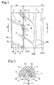
- FIG. 1 there is shown an embodiment of a tread pattern for a pneumatic tire according to the present invention.
- Reference numeral 1 denotes a tread surface, and the rotational direction R of the tire is specified in one direction as shown by an arrow.
- the plurality of circumferential grooves 2 comprise a first circumferential grooves 2A disposed at a location defining the center region 1A and each of the shoulder regions 1B on both sides thereof, two second circumferential grooves 2B disposed on both sides of a centerline CL of the tire in the center region 1A, and a third circumferential groove 1C disposed on the tire centerline CL in the center region 1A.
- Each first circumferential groove 2A extends straight along the tire circumferential direction T, and has a groove width which is the narrowest.
- Each of the second circumferential grooves 2B extends in the tire circumferential direction T, and is composed of a plurality of circularly curved groove portions 2B1, which are convex towards the tire centerline CL and are connected to one another.
- Each of the groove portions 2B1 is in the form of a circular arc having a large radius of curvature, and each second circumferential groove is a so-called see-through groove, which can be seen through from one end to the other end of the second circumferential groove 2B when the tread surface 1 is fully developed.
- the second circumferential grooves 2B have a groove width which is greater than that of the first circumferential grooves 2A.
- the third circumferential groove 2C extends straight along the tire circumferential direction T.
- the third circumferential groove is wider in groove width than each second circumferential groove 2B, and is the widest.
- first lateral grooves 3 Disposed at predetermined intervals along the tire circumferential direction Tare first lateral grooves 3 extending outward in a widthwise direction of the tire from each of the first circumferential grooves 2A so as to incline towards a direction of reverse rotation of the tire, and a plurality of blocks 4 are defined by the first circumferential grooves 2A and the first lateral grooves 3 in the shoulder regions 1B.
- Second lateral grooves 5 Disposed at predetermined intervals along the tire circumferential direction T are second lateral grooves 5 extending outward in the tire widthwise direction from each of the second circumferential grooves 2B so as to incline towards the tire reverse rotation direction, and a plurality of blocks 6 are defined by the circumferential grooves 2A and 2B, and the second lateral grooves 5 in the center region 1A.
- Ribs 7 extending along the tire circumferential direction T are formed between the circumferential grooves 2B and 2C.
- the first lateral grooves 3 are displaced substantially one-half of the intervals from the second lateral groove 5, and are substantially centrally located between the second lateral grooves 5.
- the inner end side of each first lateral groove 3 extends into each block 6, and the inner terminal end thereof is located substantially centrally of each block 6.
- the first lateral grooves 3 has a bottom surface 3a which is formed as a curved surface in the form of a circular arc in cross section, as shown in FIG. 2.
- each of the second lateral grooves 5 is in communication with a connecting part between the circularly curved groove portions 2B1.
- the outer end side of each second lateral groove 5 extends into each block 4 so as to cross and communicate with the first circumferential groove 2A, and the outer terminal end thereof is located within each block 4.
- the corner portions 4X and 6X of the blocks 4, 6 facing to the first circumferential grooves 2A each have a groove wall edge section which is formed to have a chamfered face e in the form of a circular arc in cross section.
- the chamfered faces e are inclined such that the inclination angles thereof with respect to the tire radial direction are greater than those of the groove wall surfaces 8 of the blocks facing to the first circumferential grooves 2A, which increases rigidity of the block corner portions located in the areas where noise is apt to be created, thereby suppressing generation of noise due to slippage of the block corner portions.
- Each of the blocks 4 in the shoulder regions 1B has a tire rotational direction side groove wall surface 4a and a tire reverse rotation direction side groove wall surface 4b located back and forth in the tire rotational direction R and facing to the first lateral grooves 3.
- the inclination angle ⁇ (° ) of the tire rotational direction side groove wall surface 4a and the inclination angle ⁇ (° ) of the tire reverse rotation direction side groove wall surface 4b have a relationship represented by ⁇ > ⁇
- the edge portion 4d (kicking-out side edge portion) of each block 4 on the tire reverse rotation direction side thereof has a greater rigidity than the side edge portion 4c (stepping-in side edge portion) thereof on the tire rotational direction side.
- the edge of the tire rotational direction side edge portion 4c is cut off to have a chamfered face m in the form of a circular arc in cross section.
- the chamfered face m may be in the form of a straight line in cross section.
- the kicking-out side edge portions of the blocks 4 in the shoulder regions 1B were, therefore, lower in ground contact pressure than the stepping-in side edge portions thereof, and as a result, irregular wear such that the kicking-out side edge portions wore more slowly than the stepping-in side edge portions was created, different from that in normal driving.
- the inclination angle ⁇ of the tire reverse rotation direction side groove wall surface 4b of each block 4 in the shoulder regions 1B is greater than the inclination angle ⁇ of the tire rotational direction side groove wall surface 4a thereof, as described above.
- This increases rigidity of the kicking-out side edge portions, which allows for an even distribution of ground contact pressure of the blocks 4 in running a circuit or the like where a great lateral acceleration acts during turning. Accordingly, irregular wear can be suppressed.
- the tire rotational direction side edge portion 4c is chamfered to make its rigidity greater, thereby allowing for an even distribution of ground contact pressure of the blocks 4 during normal driving also. Thus, heel-and-toe wear can be suppressed.
- the above-mentioned inclination angle ⁇ is preferably in the following range: 0.10 ⁇ tan - 1 W / 2 ⁇ D ⁇ ⁇ ⁇ 0.75 ⁇ tan - 1 W / 2 ⁇ D where D is the groove depth of the first lateral groove 3 in millimeters, and W is the groove width of the first lateral groove 3 in millimeters.
- the inclination angle ⁇ is desirably in the following range: 0.3 ⁇ tan - 1 W / 2 ⁇ D ⁇ ⁇ ⁇ 0.5 ⁇ tan - 1 W / 2 ⁇ D
- the above-mentioned inclination angle ⁇ is preferably in the following range: ⁇ ⁇ 0.9 ⁇ tan - 1 W / 2 ⁇ D
- the kicking-out side edge portions 4d of the blocks 4 are greater in rigidity and it is not preferable from the viewpoint of an even ground contact pressure distribution. More preferably, the inclination angle ⁇ is in the following range within the upper limit: 1.6 ⁇ ⁇ ⁇ ⁇ ⁇ 0.5 ⁇ ⁇
- the tire rotational direction side edge portions 4c of the blocks 4 preferably have a chamfered face m in the form of a circular arc in cross section as shown in the drawing.
- the curvature radius r of the chamfered face m is preferably in the range of 1 to 3 mm. If the curvature radius r is less than 1 mm, it is difficult to effectively suppress heel-and-toe wear in normal driving. If the curvature radius r is greater than 3 mm, it is difficult to improve irregular wear in running a circuit or the like because the edge portion 4c is greater in rigidity. Preferably, the curvature radius r is greater as the inclination angle ⁇ is smaller.
- the inclination angle ⁇ referred in the present invention is, as shown in FIG. 2, an angle between the groove wall surface 4a and a straight line J which is orthogonal at an intersection F to a straight line G drawn between the intersection F and an intersection K, the intersection F being an intersecting point of the tire rotational direction side groove wall surface 4a and the ground contact surface 4e of the block 4 before chamfering, the intersection K being an intersecting point of the tire reverse rotation direction side groove wall surface 4b and the ground contact surface 4e of the block 4.
- the inclination angle ⁇ is an angle between the groove wall surface 4b and a straight line M which is orthogonal at the intersection point K to the straight line G.
- the groove width W of the first lateral groove 3 is a length between the intersections F and K, and the groove depth D thereof is the length of a perpendicular line drawn to the straight line G from the bottom (the deepest position of the groove).
- the present invention shows a pneumatic tire also having blocks 6 in the center region 1A, but is not limited thereto.
- the present invention is preferably applicable to any of pneumatic tires having blocks 4 in at least one shoulder region 1B of the tread surface 1 and a tire rotational direction R specified in one direction.
- the tread pattern described above is preferably applied to pneumatic tires for passenger cars, especially employed for high performance vehicles with a large engine size.
- Tires according to the present invention, comparison and prior art were prepared, respectively, having a tire size of 235/45ZR17 and a tread pattern shown in FIG. 1; the present invention tires were formed such that the inclination angle ⁇ of the tire reverse rotation direction side groove wall surface of each of the blocks in the shoulder regions was greater than the inclination angle ⁇ of the tire rotational direction side groove wall surface thereof, and the tire rotational direction side edge portion thereof had a chamfered face in the form of a circular arc; the comparison tires had the same constructions as the present invention tires except that the tire rotational direction side edge portions had no chamfered face; the prior art tires had the same constructions as the comparison tires except that the inclination angle ⁇ was greater than the inclination angle ⁇ .
- the inclination angle ⁇ was equal to 0.30 ⁇ tan -1 (2D/W), the inclination angle ⁇ was equal to 0.85 ⁇ tan -1 (2D/W) and the curvature radius r of the chamfered face was 3 mm.
- the inclination angle ⁇ was 6 degrees and the inclination angle ⁇ was 2 degrees.
- test tires were seated on 17 ⁇ 8JJ sized rims, inflated to an air pressure of 200 kPa, and mounted on a passenger car of 3 liter displacement; the evaluation tests for heel-and-toe wear resistance in normal driving and irregular wear resistance when a large lateral acceleration acted thereupon were performed in the followingmeasurement methods, obtaining the results shown in Table 1.
- the car was run on a public road a distance of 4000 km, and then the remaining amounts of the opposing edge portions of respective adjacent blocks in the shoulder regions were measured in 0.5 mm intervals with the measurement value within the interval rounded up, and the maximum value of the differences between the remaining amounts of the opposing edge portions was employed as the amount of heel-and-toe wear.
- the amount of heel-and-toe wear and the amount of irregular wear according to the present invention tires are 0.5 mm, respectively, and the present invention tires can improve irregular wear resistance while maintaining heel-and-toe wear resistance equivalent to the prior art tire.
- the inclination angles ⁇ of the tire reverse rotation direction side groove wall surfaces of the blocks were greater than the inclination angles ⁇ of the tire rotational direction side groove wall surfaces thereof in the shoulder regions of the tread surface the tire rotational direction of which is specified in one direction, and the tire rotational direction side edge portions of the blocks are chamfered, whereby irregular wear created in running a circuit or the like where a great lateral acceleration is applied thereto during turning can be improved without degrading heel-and-toe wear resistance in normal driving.
- the pneumatic tires having the aforementioned excellent effects are very effectively used as pneumatic tires which are employed when general car users make their cars run a circuit or the like in which a large lateral acceleration is applied thereto during turning.
Description
- The present invention relates to pneumatic tires.
- Conventionally, there are proposed many pneumatic tires having a tread surface which is provided with a directional tread pattern the tire rotational direction of which is specified in one direction. In the pneumatic tires having such a directional tread pattern, there are pneumatic tires including a tread surface having circumferential grooves extending in a circumferential direction of the tire, and lateral grooves extending in a widthwise direction of the tire and disposed at given intervals in the tire circumferential direction to thereby define blocks in its shoulder regions (for example, see Unexamined
Japanese Patent Application Publication No. 11-91313 - In recent years, circuit courses are opened up to general car users, and the users often have chances to make their cars run a circuit course. When running such a circuit course, a lateral acceleration acting during turning is much greater, compared with that in normal driving when running a public road, and irregular wear different from that in the normal driving is, therefore, created.
- In the pneumatic tires having the above-mentioned directional pattern of blocks, the normal driving produces heel-and-toe wear such that the edge portions (stepping-in side edge portions), on a direction side of reverse rotation of the tire, of the blocks facing to the lateral grooves wear more slowly than the edge portions (kicking-out side edge portions) thereof on a direction side of rotation of the tire. Therefore, the inclination angles of the stepping-in side groove wall surfaces of the blocks are greater than the inclination angles of the kicking-out side groove wall surfaces thereof to increase rigidity of the stepping-in side edge portions, thereby suppressing heel-and-toe wear.
- However, when running a circuit with such a tire, there is a problem of occurrence of irregular wear such that the kicking-out side edge portions of the blocks wear more slowly than the stepping-in side edge portions thereof.
-
JP 2002 087 021.A claim 1, discloses a tyre tread pattern with a predetermined direction of rotation, having lateral grooves (2) extending widthwise on both sides of the tread from a central circumferential groove (E) to define blocks (3). -
EP-A-0 602 989 discloses a tyre tread pattern of lateral (4) and circumferential (3A,3B) grooves defining blocks (BM,BS). The edges of the blocks (BM,BS) are everywhere chamfered, so as to reduce noise generation. -
EP-A-1 106 395 discloses a tyre tread pattern in which the edges of a central circumferential groove are chamfered so as to prevent demoulding defects. - According to the present invention, there is provided a pneumatic tire having a tread surface having a direction of rotation (R) of the tire which is specified in one direction, the tread surface having a center region and shoulder regions on both sides of the center region, blocks being defined in at least one of the shoulder regions by at least one first circumferential groove which extends in a circumferential direction (T) of the tire and first lateral grooves which extend in a widthwise direction of the tire and are disposed at predetermined intervals in the tire circumferential direction, wherein each of the blocks has a tire rotational direction side groove wall surface and a tire reverse rotation direction side groove wall surface located back and forth in the tire rotational direction (R) and facing to the first lateral grooves, the tire reverse rotation direction side groove wall surface having an inclination angle β greater than the inclination angle α of the tire rotational direction side groove wall surface, characterized in that:
- each of the blocks has a tire rotational direction side edge portion which is chamfered and the tire reverse rotation direction side groove wall surface of each block intersects a ground contact surface of the block at an intersection K.
- It is possible with embodiments of the present invention to provide a pneumatic tire which can improve irregular wear produced in running a circuit or the like where a large lateral acceleration is applied thereto during turning, without degrading heel-and-toe wear resistance in normal driving.
- According to the present invention described above, the inclination angle β of the tire reverse rotation direction side groove wall surface of each block is greater to thereby make the kicking-out side edge portion thereof where wear grows slower due to a lower ground contact surface pressure higher in rigidity than the stepping-in side edge portion thereof, which allows for a more even distribution of ground contact pressure of the blocks in the shoulder region in running a circuit or the like where a large lateral acceleration acts during turning. Accordingly, irregular wear can be improved.
- The tire rotational direction side edge portions are chamfered to make its rigidity greater, thereby allowing for an even distribution of ground contact pressure of the blocks in normal driving. Therefore, heel-and-toe wear can be suppressed.
- To enable a better understanding of the present invention, and to show how the same may be carried into effect, reference will now be made, by way of example only, to the accompanying drawings, in which:-
- FIG. 1 is a partial development view showing an embodiment of a pneumatic tire according to the present invention, in which one side of the tread surface with respect to the centerline of the tire is developed; and
- FIG. 2 is a partial enlarged cross-sectional view of the blocks taken along a circumferential direction of the tire.
- An embodiment of a pneumatic tire in accordance with the present invention will be described in detail below with reference to the drawings.
- Referring to FIG. 1, there is shown an embodiment of a tread pattern for a pneumatic tire according to the present invention.
Reference numeral 1 denotes a tread surface, and the rotational direction R of the tire is specified in one direction as shown by an arrow. Thetread surface 1, which has a center region 1A andshoulder regions 1B on both sides of the center region, includes a plurality ofcircumferential grooves 2 extending along a circumferential direction T of the titre. The plurality ofcircumferential grooves 2 comprise a firstcircumferential grooves 2A disposed at a location defining the center region 1A and each of theshoulder regions 1B on both sides thereof, two second circumferential grooves 2B disposed on both sides of a centerline CL of the tire in the center region 1A, and a third circumferential groove 1C disposed on the tire centerline CL in the center region 1A. - Each first
circumferential groove 2A extends straight along the tire circumferential direction T, and has a groove width which is the narrowest. - Each of the second circumferential grooves 2B extends in the tire circumferential direction T, and is composed of a plurality of circularly curved groove portions 2B1, which are convex towards the tire centerline CL and are connected to one another. Each of the groove portions 2B1 is in the form of a circular arc having a large radius of curvature, and each second circumferential groove is a so-called see-through groove, which can be seen through from one end to the other end of the second circumferential groove 2B when the
tread surface 1 is fully developed. The second circumferential grooves 2B have a groove width which is greater than that of the firstcircumferential grooves 2A. - The third
circumferential groove 2C extends straight along the tire circumferential direction T. The third circumferential groove is wider in groove width than each second circumferential groove 2B, and is the widest. - Disposed at predetermined intervals along the tire circumferential direction Tare first
lateral grooves 3 extending outward in a widthwise direction of the tire from each of the firstcircumferential grooves 2A so as to incline towards a direction of reverse rotation of the tire, and a plurality ofblocks 4 are defined by the firstcircumferential grooves 2A and the firstlateral grooves 3 in theshoulder regions 1B. - Disposed at predetermined intervals along the tire circumferential direction T are second
lateral grooves 5 extending outward in the tire widthwise direction from each of the second circumferential grooves 2B so as to incline towards the tire reverse rotation direction, and a plurality ofblocks 6 are defined by thecircumferential grooves 2A and 2B, and the secondlateral grooves 5 in the center region 1A.Ribs 7 extending along the tire circumferential direction T are formed between thecircumferential grooves 2B and 2C. - The first
lateral grooves 3 are displaced substantially one-half of the intervals from the secondlateral groove 5, and are substantially centrally located between the secondlateral grooves 5. The inner end side of each firstlateral groove 3 extends into eachblock 6, and the inner terminal end thereof is located substantially centrally of eachblock 6. The firstlateral grooves 3 has abottom surface 3a which is formed as a curved surface in the form of a circular arc in cross section, as shown in FIG. 2. - The inner terminal end of each of the second
lateral grooves 5 is in communication with a connecting part between the circularly curved groove portions 2B1. The outer end side of each secondlateral groove 5 extends into eachblock 4 so as to cross and communicate with the firstcircumferential groove 2A, and the outer terminal end thereof is located within eachblock 4. - The
corner portions blocks circumferential grooves 2A each have a groove wall edge section which is formed to have a chamfered face e in the form of a circular arc in cross section. The chamfered faces e are inclined such that the inclination angles thereof with respect to the tire radial direction are greater than those of thegroove wall surfaces 8 of the blocks facing to the firstcircumferential grooves 2A, which increases rigidity of the block corner portions located in the areas where noise is apt to be created, thereby suppressing generation of noise due to slippage of the block corner portions. - Each of the
blocks 4 in theshoulder regions 1B has a tire rotational direction side groove wall surface 4a and a tire reverse rotation direction sidegroove wall surface 4b located back and forth in the tire rotational direction R and facing to the firstlateral grooves 3. As shown in FIG. 2, the inclination angle α (° ) of the tire rotational direction side groove wall surface 4a and the inclination angle β (° ) of the tire reverse rotation direction sidegroove wall surface 4b have a relationship represented by β>α, and theedge portion 4d (kicking-out side edge portion) of eachblock 4 on the tire reverse rotation direction side thereof has a greater rigidity than theside edge portion 4c (stepping-in side edge portion) thereof on the tire rotational direction side. - The edge of the tire rotational direction
side edge portion 4c is cut off to have a chamfered face m in the form of a circular arc in cross section. The chamfered face m may be in the form of a straight line in cross section. - It was very hard to learn the ground contact state of a tire when running a circuit in which a lateral acceleration acting during turning was much greater, compared with that in normal driving, before. However, with progress in hardware recently, the ground contact state of a tire has been possible to be simulated under such conditions. The simulation showed that a force acted substantially at a right angle to the tire during turning in a circuit, and the tread surface contacted with the ground with its ground contact shape being substantially of a triangle the top of which was located on the force acting side. The kicking-out side edge portions of the
blocks 4 in theshoulder regions 1B were, therefore, lower in ground contact pressure than the stepping-in side edge portions thereof, and as a result, irregular wear such that the kicking-out side edge portions wore more slowly than the stepping-in side edge portions was created, different from that in normal driving. - Therefore, according to the present invention, the inclination angle β of the tire reverse rotation direction side
groove wall surface 4b of eachblock 4 in theshoulder regions 1B is greater than the inclination angle α of the tire rotational direction side groove wall surface 4a thereof, as described above. This increases rigidity of the kicking-out side edge portions, which allows for an even distribution of ground contact pressure of theblocks 4 in running a circuit or the like where a great lateral acceleration acts during turning. Accordingly, irregular wear can be suppressed. - The tire rotational direction
side edge portion 4c is chamfered to make its rigidity greater, thereby allowing for an even distribution of ground contact pressure of theblocks 4 during normal driving also. Thus, heel-and-toe wear can be suppressed. - In the present invention, the above-mentioned inclination angle α is preferably in the following range:

where D is the groove depth of the firstlateral groove 3 in millimeters, and W is the groove width of the firstlateral groove 3 in millimeters. - If the inclination angle α is below the lower limit, there is bad affection on heel-and-toe wear during normal driving. If the inclination angle α is beyond the upper limit, it is not preferable because the
bottom surfaces 3a of the firstlateral grooves 3 which are in the form of circular arcs in cross section are narrowed, whereby cracks are apt to occur in thebottom surfaces 3a and the groove areas decrease quickly as the blocks wear. The inclination angle α is desirably in the following range:
- The above-mentioned inclination angle β is preferably in the following range:

- If the inclination angle β is beyond the upper limit, the kicking-out
side edge portions 4d of theblocks 4 are greater in rigidity and it is not preferable from the viewpoint of an even ground contact pressure distribution. More preferably, the inclination angle β is in the following range within the upper limit:
- The tire rotational direction
side edge portions 4c of theblocks 4 preferably have a chamfered face m in the form of a circular arc in cross section as shown in the drawing. The curvature radius r of the chamfered face m is preferably in the range of 1 to 3 mm. If the curvature radius r is less than 1 mm, it is difficult to effectively suppress heel-and-toe wear in normal driving. If the curvature radius r is greater than 3 mm, it is difficult to improve irregular wear in running a circuit or the like because theedge portion 4c is greater in rigidity. Preferably, the curvature radius r is greater as the inclination angle α is smaller. - The inclination angle α referred in the present invention is, as shown in FIG. 2, an angle between the groove wall surface 4a and a straight line J which is orthogonal at an intersection F to a straight line G drawn between the intersection F and an intersection K, the intersection F being an intersecting point of the tire rotational direction side groove wall surface 4a and the
ground contact surface 4e of theblock 4 before chamfering, the intersection K being an intersecting point of the tire reverse rotation direction sidegroove wall surface 4b and theground contact surface 4e of theblock 4. The inclination angle β is an angle between thegroove wall surface 4b and a straight line M which is orthogonal at the intersection point K to the straight line G. - The groove width W of the first
lateral groove 3 is a length between the intersections F and K, and the groove depth D thereof is the length of a perpendicular line drawn to the straight line G from the bottom (the deepest position of the groove). - In the above embodiment, the present invention shows a pneumatic tire also having
blocks 6 in the center region 1A, but is not limited thereto. The present invention is preferably applicable to any of pneumatictires having blocks 4 in at least oneshoulder region 1B of thetread surface 1 and a tire rotational direction R specified in one direction. - The tread pattern described above is preferably applied to pneumatic tires for passenger cars, especially employed for high performance vehicles with a large engine size.
- Tires according to the present invention, comparison and prior art were prepared, respectively, having a tire size of 235/45ZR17 and a tread pattern shown in FIG. 1; the present invention tires were formed such that the inclination angle β of the tire reverse rotation direction side groove wall surface of each of the blocks in the shoulder regions was greater than the inclination angle α of the tire rotational direction side groove wall surface thereof, and the tire rotational direction side edge portion thereof had a chamfered face in the form of a circular arc; the comparison tires had the same constructions as the present invention tires except that the tire rotational direction side edge portions had no chamfered face; the prior art tires had the same constructions as the comparison tires except that the inclination angle α was greater than the inclination angle β.
- In the present invention tires, the inclination angle α was equal to 0.30×tan-1 (2D/W), the inclination angle β was equal to 0.85×tan-1 (2D/W) and the curvature radius r of the chamfered face was 3 mm. In the prior art tires, the inclination angle α was 6 degrees and the inclination angle β was 2 degrees.
- The test tires were seated on 17 × 8JJ sized rims, inflated to an air pressure of 200 kPa, and mounted on a passenger car of 3 liter displacement; the evaluation tests for heel-and-toe wear resistance in normal driving and irregular wear resistance when a large lateral acceleration acted thereupon were performed in the followingmeasurement methods, obtaining the results shown in Table 1.
- The car was run on a public road a distance of 4000 km, and then the remaining amounts of the opposing edge portions of respective adjacent blocks in the shoulder regions were measured in 0.5 mm intervals with the measurement value within the interval rounded up, and the maximum value of the differences between the remaining amounts of the opposing edge portions was employed as the amount of heel-and-toe wear.
- The car was run on a dry asphalt road surface, drawing a figure-8 with a lateral acceleration acting upon the car being 0.8G, and after repeating it 500 times, the amount of irregular wear was measured as described above.
Table 1 Prior Art Tire Present Invention Tire Comparison Tire Heel-and-toe wear Resistance (mm) 0.5 0.5 1.5 Irregular Wear Resistance (mm) 2.0 0.5 0.5 - As can be seen from Table 1, the amount of heel-and-toe wear and the amount of irregular wear according to the present invention tires are 0.5 mm, respectively, and the present invention tires can improve irregular wear resistance while maintaining heel-and-toe wear resistance equivalent to the prior art tire.
- As having been illustrated above, according to the present invention, the inclination angles β of the tire reverse rotation direction side groove wall surfaces of the blocks were greater than the inclination angles α of the tire rotational direction side groove wall surfaces thereof in the shoulder regions of the tread surface the tire rotational direction of which is specified in one direction, and the tire rotational direction side edge portions of the blocks are chamfered, whereby irregular wear created in running a circuit or the like where a great lateral acceleration is applied thereto during turning can be improved without degrading heel-and-toe wear resistance in normal driving.
- The pneumatic tires having the aforementioned excellent effects are very effectively used as pneumatic tires which are employed when general car users make their cars run a circuit or the like in which a large lateral acceleration is applied thereto during turning.
Claims (17)
- A pneumatic tire having a tread surface (1) having a direction of rotation (R) of the tire which is specified in one direction, the tread surface having a center region (1A) and shoulder regions (1B) on both sides of the center region, blocks (4) being defined in at least one of the shoulder regions by at least one first circumferential groove (2A) which extends in a circumferential direction (T) of the tire and first lateral grooves (3) which extend in a widthwise direction of the tire and are disposed at predetermined intervals in the tire circumferential direction,
wherein each of the blocks (4) has a tire rotational direction side groove wall surface (4a) and a tire reverse rotation direction side groove wall surface (4b) located back and forth in the tire rotational direction (R) and facing to the first lateral grooves (3), the tire reverse rotation direction side groove wall surface having an inclination angle β greater than the inclination angle α of the tire rotational direction side groove wall surface, characterized in that:each of the blocks (4) has a tire rotational direction side edge portion (4c) which is chamfered and the tire reverse rotation direction side groove wall surface (4b) of each block (4) intersects a ground contact surface (4e) of the block (4) at an intersection K. - A pneumatic tire according to claim 1, wherein the inclination angle α fulfills the following relationship:

where D is the groove depth of the first lateral groove, and W is the groove width of the first lateral groove. - A pneumatic tire according to claim 2, wherein the inclination angle α fulfills the following relationship:

- A pneumatic tire according to claim 2 or 3, wherein the inclination angle β fulfills the following relationship:

- A pneumatic tire according to claim 4, wherein the inclination β fulfills the following relationship:

- A pneumatic tire according to any one of claims 1 to 5, wherein the tire rotational direction side edge portions (4c) of the blocks (4) are chamfered in the form of circular arcs having a curvature radius of 1 to 3 mm.
- A pneumatic tire according to any one of claims 1 to 6, wherein the first circumferential groove (2A) is disposed between the center region (1A) and the at least one shoulder region (1B).
- A pneumatic tire according to any one of claims 1 to 7, wherein the first lateral grooves (3) extend outwardly in the tire widthwise direction from the first circumferential groove so as to incline towards the tire reverse rotation direction.
- A pneumatic tire according to claim 7, wherein the tread surface (1) has two first circumferential grooves (2A), each of the first circumferential grooves (2A) being disposed between the center region (1A) and each of the shoulder regions (1B), the first lateral grooves (3) extending outwardly in the tire widthwise direction from each first circumferential groove (2A) so as to incline towards the tire reverse rotation direction.
- A pneumatic tire according to claim 9, wherein two second circumferential grooves (2B) extending in the tire circumferential direction (T) are provided on both sides of a centerline (CL) of the tire in the center region (1A), and wherein second lateral grooves (5) extending outwardly in the tire widthwise direction from each of the second circumferential grooves so as to incline towards the tire reverse rotation direction are disposed at predetermined intervals in the tire circumferential direction, blocks (6) being defined by the first circumferential grooves (2A), the second circumferential grooves (2B) and the second lateral grooves (5).
- A pneumatic tire according to claim 10, wherein each second circumferential groove (2B) is composed of a plurality of circularly curved groove portions (2B1) which extend in the tire circumferential direction (T), the groove portions being convex towards the tire centerline and connected to one another.
- A pneumatic tire according to claim 11, wherein the second lateral grooves (5) extend outwardly in the tire widthwise direction beyond the first circumferential groove (2A) from the connecting parts of the circularly curved groove portions (2B1).
- A pneumatic tire according to any one of claims 10 to 12, wherein the second lateral grooves (5) are displaced substantially one-half of the intervals from the first lateral grooves (3).
- A pneumatic tire according to claim 13, wherein the second lateral grooves (5) extend into the blocks (4) in each shoulder region (1B).
- A pneumatic tire according to any one of claims 10 to 14, wherein a third circumferential groove (2C) extending in the tire circumferential direction (T) is provided on the tire centreline (CL), a rib (7) being defined between the third circumferential groove (2C) and each second circumferential groove (2B).
- A pneumatic tire according to claim 15, wherein the third circumferential groove (2C) has a groove width greater than that of each second circumferential groove (2B), and wherein each first circumferential groove (2A) has a groove width smaller than that of each second circumferential groove (2B).
- A pneumatic tire according to any one of claims 1 to 16, wherein an edge portion (4d) at the intersection K on the tire reverse rotation direction side of each block (4) has a greater rigidity than the chamfered side edge portion (4c) on the tire rotational direction side of each block (4).
Applications Claiming Priority (3)
| Application Number | Priority Date | Filing Date | Title |
|---|---|---|---|
| JP2002351306 | 2002-12-03 | ||
| JP2002351306A JP4309119B2 (en) | 2002-12-03 | 2002-12-03 | Pneumatic tire |
| PCT/JP2003/015185 WO2004050389A1 (en) | 2002-12-03 | 2003-11-27 | Pneumatic tire |
Publications (3)
| Publication Number | Publication Date |
|---|---|
| EP1568516A1 EP1568516A1 (en) | 2005-08-31 |
| EP1568516A4 EP1568516A4 (en) | 2006-05-31 |
| EP1568516B1 true EP1568516B1 (en) | 2008-01-09 |
Family
ID=32463143
Family Applications (1)
| Application Number | Title | Priority Date | Filing Date |
|---|---|---|---|
| EP03775935A Expired - Lifetime EP1568516B1 (en) | 2002-12-03 | 2003-11-27 | Pneumatic tire |
Country Status (8)
| Country | Link |
|---|---|
| US (1) | US7416003B2 (en) |
| EP (1) | EP1568516B1 (en) |
| JP (1) | JP4309119B2 (en) |
| KR (1) | KR101002918B1 (en) |
| CN (1) | CN100348431C (en) |
| CA (1) | CA2501151C (en) |
| DE (1) | DE60318620T2 (en) |
| WO (1) | WO2004050389A1 (en) |
Families Citing this family (6)
| Publication number | Priority date | Publication date | Assignee | Title |
|---|---|---|---|---|
| KR100644872B1 (en) | 2004-09-23 | 2006-11-15 | 금호타이어 주식회사 | Studless Type Heavy duty Pneumatic Radial Tire |
| CA2589272A1 (en) * | 2004-11-29 | 2006-06-01 | Pirelli Tyre S.P.A. | On/off-road tire for a motor vehicle |
| JP4145346B1 (en) * | 2007-11-07 | 2008-09-03 | 横浜ゴム株式会社 | Pneumatic tire |
| USD608724S1 (en) | 2009-03-16 | 2010-01-26 | Trek Bicycle Corporation | Bicycle tire tread |
| EP2930035B1 (en) * | 2012-11-30 | 2019-08-21 | Bridgestone Corporation | Pneumatic tire |
| JP5728035B2 (en) * | 2013-01-24 | 2015-06-03 | 住友ゴム工業株式会社 | Pneumatic tire |
Family Cites Families (30)
| Publication number | Priority date | Publication date | Assignee | Title |
|---|---|---|---|---|
| US2878852A (en) * | 1955-11-15 | 1959-03-24 | Us Rubber Co | Pneumatic tire having noiseless tread |
| US3768535A (en) * | 1971-12-03 | 1973-10-30 | E Holden | Tire tread |
| JPS6222103U (en) * | 1985-07-25 | 1987-02-10 | ||
| JPS6226104A (en) * | 1985-07-26 | 1987-02-04 | Yokohama Rubber Co Ltd:The | Pneumatic radial tire for passenger car |
| GB2192842B (en) * | 1986-06-13 | 1991-01-30 | Bridgestone Corp | Pneumatic tire |
| JPH0536963Y2 (en) * | 1987-08-27 | 1993-09-20 | ||
| JP2886540B2 (en) * | 1988-11-24 | 1999-04-26 | 株式会社ブリヂストン | Flat pneumatic radial tire |
| JPH02179507A (en) * | 1988-12-29 | 1990-07-12 | Bridgestone Corp | Pneumatic tire |
| JPH02204105A (en) * | 1989-01-31 | 1990-08-14 | Sumitomo Rubber Ind Ltd | Pneumatic tire |
| US5327952A (en) * | 1991-03-08 | 1994-07-12 | The Goodyear Tire & Rubber Company | Pneumatic tire having improved wet traction |
| JPH0648122A (en) * | 1992-07-30 | 1994-02-22 | Yokohama Rubber Co Ltd:The | Pneumatic radial tire for heavy load |
| DE4239475A1 (en) * | 1992-11-25 | 1994-05-26 | Continental Ag | Tyre tread with minimal aquaplaning - has sets of longer and shorter arc-shaped grooves running at acute angle from and back to edge, meeting edges at different points |
| JPH06166303A (en) * | 1992-12-01 | 1994-06-14 | Yokohama Rubber Co Ltd:The | Pneumatic tire |
| EP0602989A1 (en) * | 1992-12-16 | 1994-06-22 | Sumitomo Rubber Industries, Co. Ltd | Pneumatic tyre |
| JPH06234305A (en) * | 1992-12-16 | 1994-08-23 | Sumitomo Rubber Ind Ltd | Pneumatic tire |
| JP3162866B2 (en) * | 1993-03-16 | 2001-05-08 | 株式会社ブリヂストン | Pneumatic tire |
| JP3321262B2 (en) * | 1993-09-10 | 2002-09-03 | 株式会社ブリヂストン | Heavy-duty pneumatic tires for construction vehicles |
| JP3471396B2 (en) * | 1993-12-17 | 2003-12-02 | 横浜ゴム株式会社 | Pneumatic radial tires for passenger cars |
| JP3516742B2 (en) * | 1994-11-22 | 2004-04-05 | 株式会社ブリヂストン | Pneumatic radial tire |
| JPH10175405A (en) * | 1996-12-19 | 1998-06-30 | Sumitomo Rubber Ind Ltd | Radial tire for heavy load |
| DE19708612A1 (en) * | 1997-03-03 | 1998-09-10 | Sp Reifenwerke Gmbh | Vehicle tires |
| JP3774551B2 (en) | 1997-09-25 | 2006-05-17 | 横浜ゴム株式会社 | Pneumatic radial tire |
| JP3967820B2 (en) * | 1998-03-18 | 2007-08-29 | 株式会社ブリヂストン | Pneumatic tire |
| JP2000071718A (en) * | 1998-08-28 | 2000-03-07 | Bridgestone Corp | Pneumatic tire |
| US6340040B1 (en) * | 1998-10-30 | 2002-01-22 | Sumitomo Rubber Industries, Ltd. | Vehicle tire including main grooves and lug grooves |
| DE19937067A1 (en) * | 1999-08-05 | 2001-02-08 | Dunlop Gmbh | Vehicle tires with a tread pattern |
| US6640858B2 (en) * | 1999-12-07 | 2003-11-04 | Sumitomo Rubber Industries, Ltd. | Tire having tread grooves having right-hand groove wall and left-hand groove wall |
| JP3441705B2 (en) * | 2000-08-22 | 2003-09-02 | 住友ゴム工業株式会社 | Pneumatic tire |
| JP2002087021A (en) * | 2000-09-14 | 2002-03-26 | Yokohama Rubber Co Ltd:The | Pneumatic radial tire |
| JP4017503B2 (en) * | 2002-11-19 | 2007-12-05 | 横浜ゴム株式会社 | Pneumatic tire |
-
2002
- 2002-12-03 JP JP2002351306A patent/JP4309119B2/en not_active Expired - Fee Related
-
2003
- 2003-11-27 EP EP03775935A patent/EP1568516B1/en not_active Expired - Lifetime
- 2003-11-27 KR KR1020057008733A patent/KR101002918B1/en not_active IP Right Cessation
- 2003-11-27 WO PCT/JP2003/015185 patent/WO2004050389A1/en active IP Right Grant
- 2003-11-27 DE DE60318620T patent/DE60318620T2/en not_active Expired - Lifetime
- 2003-11-27 CA CA2501151A patent/CA2501151C/en not_active Expired - Fee Related
- 2003-11-27 US US10/532,070 patent/US7416003B2/en not_active Expired - Fee Related
- 2003-11-27 CN CNB200380104839XA patent/CN100348431C/en not_active Expired - Fee Related
Also Published As
| Publication number | Publication date |
|---|---|
| KR101002918B1 (en) | 2010-12-27 |
| DE60318620T2 (en) | 2008-12-24 |
| CN1720151A (en) | 2006-01-11 |
| JP2004182075A (en) | 2004-07-02 |
| EP1568516A1 (en) | 2005-08-31 |
| KR20050086666A (en) | 2005-08-30 |
| WO2004050389A1 (en) | 2004-06-17 |
| DE60318620D1 (en) | 2008-02-21 |
| US20060060277A1 (en) | 2006-03-23 |
| EP1568516A4 (en) | 2006-05-31 |
| US7416003B2 (en) | 2008-08-26 |
| CA2501151A1 (en) | 2004-06-17 |
| JP4309119B2 (en) | 2009-08-05 |
| CN100348431C (en) | 2007-11-14 |
| CA2501151C (en) | 2011-02-08 |
Similar Documents
| Publication | Publication Date | Title |
|---|---|---|
| EP3219516B1 (en) | Pneumatic tire | |
| EP3118026B1 (en) | Pneumatic tire | |
| EP3118025B1 (en) | Pneumatic tire | |
| EP2179868B1 (en) | Pneumatic tire | |
| EP2239153B1 (en) | Pneumatic tire | |
| EP3056359A1 (en) | Pneumatic tire | |
| EP1036029B1 (en) | Tire having sacrificial bridging | |
| EP1070606A2 (en) | Pneumatic tire | |
| EP2692543B1 (en) | Pneumatic tire | |
| US11541692B2 (en) | Tyre | |
| EP1818189B1 (en) | Pneumatic tire | |
| CN105711342A (en) | Pneumatic tire | |
| CN1812891A (en) | Pneumatic tire | |
| EP1568515B1 (en) | Pneumatic tire | |
| JP2886540B2 (en) | Flat pneumatic radial tire | |
| EP1568516B1 (en) | Pneumatic tire | |
| EP3075571A2 (en) | Tire | |
| EP1145873B1 (en) | Vehicle tyre | |
| JP4285617B2 (en) | Pneumatic radial tire | |
| US7861755B2 (en) | Pneumatic tire with tread having middle rib, middle lateral grooves, assistant grooves and lateral narrow grooves | |
| EP3566885B1 (en) | Tire | |
| JPH08318709A (en) | Pneumatic tire | |
| US11584166B2 (en) | Tyre | |
| EP4144541A1 (en) | Tire | |
| JP7293840B2 (en) | pneumatic tire |
Legal Events
| Date | Code | Title | Description |
|---|---|---|---|
| PUAI | Public reference made under article 153(3) epc to a published international application that has entered the european phase |
Free format text: ORIGINAL CODE: 0009012 |
|
| 17P | Request for examination filed |
Effective date: 20050503 |
|
| AK | Designated contracting states |
Kind code of ref document: A1 Designated state(s): DE FR GB IT |
|
| A4 | Supplementary search report drawn up and despatched |
Effective date: 20060421 |
|
| RIC1 | Information provided on ipc code assigned before grant |
Ipc: B60C 11/13 20060101AFI20040623BHEP Ipc: B60C 11/03 20060101ALI20060413BHEP Ipc: B60C 11/11 20060101ALI20060413BHEP |
|
| 17Q | First examination report despatched |
Effective date: 20061212 |
|
| GRAP | Despatch of communication of intention to grant a patent |
Free format text: ORIGINAL CODE: EPIDOSNIGR1 |
|
| GRAS | Grant fee paid |
Free format text: ORIGINAL CODE: EPIDOSNIGR3 |
|
| GRAA | (expected) grant |
Free format text: ORIGINAL CODE: 0009210 |
|
| AK | Designated contracting states |
Kind code of ref document: B1 Designated state(s): DE FR GB IT |
|
| REG | Reference to a national code |
Ref country code: GB Ref legal event code: FG4D |
|
| REF | Corresponds to: |
Ref document number: 60318620 Country of ref document: DE Date of ref document: 20080221 Kind code of ref document: P |
|
| ET | Fr: translation filed | ||
| PLBE | No opposition filed within time limit |
Free format text: ORIGINAL CODE: 0009261 |
|
| STAA | Information on the status of an ep patent application or granted ep patent |
Free format text: STATUS: NO OPPOSITION FILED WITHIN TIME LIMIT |
|
| 26N | No opposition filed |
Effective date: 20081010 |
|
| PGFP | Annual fee paid to national office [announced via postgrant information from national office to epo] |
Ref country code: FR Payment date: 20141110 Year of fee payment: 12 Ref country code: DE Payment date: 20141118 Year of fee payment: 12 Ref country code: GB Payment date: 20141126 Year of fee payment: 12 |
|
| PGFP | Annual fee paid to national office [announced via postgrant information from national office to epo] |
Ref country code: IT Payment date: 20141020 Year of fee payment: 12 |
|
| REG | Reference to a national code |
Ref country code: DE Ref legal event code: R119 Ref document number: 60318620 Country of ref document: DE |
|
| GBPC | Gb: european patent ceased through non-payment of renewal fee |
Effective date: 20151127 |
|
| PG25 | Lapsed in a contracting state [announced via postgrant information from national office to epo] |
Ref country code: IT Free format text: LAPSE BECAUSE OF NON-PAYMENT OF DUE FEES Effective date: 20151127 |
|
| REG | Reference to a national code |
Ref country code: FR Ref legal event code: ST Effective date: 20160729 |
|
| PG25 | Lapsed in a contracting state [announced via postgrant information from national office to epo] |
Ref country code: DE Free format text: LAPSE BECAUSE OF NON-PAYMENT OF DUE FEES Effective date: 20160601 Ref country code: GB Free format text: LAPSE BECAUSE OF NON-PAYMENT OF DUE FEES Effective date: 20151127 |
|
| PG25 | Lapsed in a contracting state [announced via postgrant information from national office to epo] |
Ref country code: FR Free format text: LAPSE BECAUSE OF NON-PAYMENT OF DUE FEES Effective date: 20151130 |