EP3075571A2 - Tire - Google Patents
Tire Download PDFInfo
- Publication number
- EP3075571A2 EP3075571A2 EP16160074.7A EP16160074A EP3075571A2 EP 3075571 A2 EP3075571 A2 EP 3075571A2 EP 16160074 A EP16160074 A EP 16160074A EP 3075571 A2 EP3075571 A2 EP 3075571A2
- Authority
- EP
- European Patent Office
- Prior art keywords
- inclined grooves
- tire
- block
- tread
- outboard
- Prior art date
- Legal status (The legal status is an assumption and is not a legal conclusion. Google has not performed a legal analysis and makes no representation as to the accuracy of the status listed.)
- Granted
Links
Images


Classifications
-
- B—PERFORMING OPERATIONS; TRANSPORTING
- B60—VEHICLES IN GENERAL
- B60C—VEHICLE TYRES; TYRE INFLATION; TYRE CHANGING; CONNECTING VALVES TO INFLATABLE ELASTIC BODIES IN GENERAL; DEVICES OR ARRANGEMENTS RELATED TO TYRES
- B60C11/00—Tyre tread bands; Tread patterns; Anti-skid inserts
- B60C11/03—Tread patterns
- B60C11/0304—Asymmetric patterns
-
- B—PERFORMING OPERATIONS; TRANSPORTING
- B60—VEHICLES IN GENERAL
- B60C—VEHICLE TYRES; TYRE INFLATION; TYRE CHANGING; CONNECTING VALVES TO INFLATABLE ELASTIC BODIES IN GENERAL; DEVICES OR ARRANGEMENTS RELATED TO TYRES
- B60C11/00—Tyre tread bands; Tread patterns; Anti-skid inserts
- B60C11/03—Tread patterns
- B60C11/0327—Tread patterns characterised by special properties of the tread pattern
-
- B—PERFORMING OPERATIONS; TRANSPORTING
- B60—VEHICLES IN GENERAL
- B60C—VEHICLE TYRES; TYRE INFLATION; TYRE CHANGING; CONNECTING VALVES TO INFLATABLE ELASTIC BODIES IN GENERAL; DEVICES OR ARRANGEMENTS RELATED TO TYRES
- B60C11/00—Tyre tread bands; Tread patterns; Anti-skid inserts
- B60C11/03—Tread patterns
- B60C11/0302—Tread patterns directional pattern, i.e. with main rolling direction
-
- B—PERFORMING OPERATIONS; TRANSPORTING
- B60—VEHICLES IN GENERAL
- B60C—VEHICLE TYRES; TYRE INFLATION; TYRE CHANGING; CONNECTING VALVES TO INFLATABLE ELASTIC BODIES IN GENERAL; DEVICES OR ARRANGEMENTS RELATED TO TYRES
- B60C11/00—Tyre tread bands; Tread patterns; Anti-skid inserts
- B60C11/03—Tread patterns
- B60C11/11—Tread patterns in which the raised area of the pattern consists only of isolated elements, e.g. blocks
-
- B—PERFORMING OPERATIONS; TRANSPORTING
- B60—VEHICLES IN GENERAL
- B60C—VEHICLE TYRES; TYRE INFLATION; TYRE CHANGING; CONNECTING VALVES TO INFLATABLE ELASTIC BODIES IN GENERAL; DEVICES OR ARRANGEMENTS RELATED TO TYRES
- B60C11/00—Tyre tread bands; Tread patterns; Anti-skid inserts
- B60C11/03—Tread patterns
- B60C11/12—Tread patterns characterised by the use of narrow slits or incisions, e.g. sipes
- B60C11/1236—Tread patterns characterised by the use of narrow slits or incisions, e.g. sipes with special arrangements in the tread pattern
-
- B—PERFORMING OPERATIONS; TRANSPORTING
- B60—VEHICLES IN GENERAL
- B60C—VEHICLE TYRES; TYRE INFLATION; TYRE CHANGING; CONNECTING VALVES TO INFLATABLE ELASTIC BODIES IN GENERAL; DEVICES OR ARRANGEMENTS RELATED TO TYRES
- B60C11/00—Tyre tread bands; Tread patterns; Anti-skid inserts
- B60C11/03—Tread patterns
- B60C11/0311—Patterns comprising tread lugs arranged parallel or oblique to the axis of rotation
- B60C2011/0313—Patterns comprising tread lugs arranged parallel or oblique to the axis of rotation directional type
-
- B—PERFORMING OPERATIONS; TRANSPORTING
- B60—VEHICLES IN GENERAL
- B60C—VEHICLE TYRES; TYRE INFLATION; TYRE CHANGING; CONNECTING VALVES TO INFLATABLE ELASTIC BODIES IN GENERAL; DEVICES OR ARRANGEMENTS RELATED TO TYRES
- B60C11/00—Tyre tread bands; Tread patterns; Anti-skid inserts
- B60C11/03—Tread patterns
- B60C11/0327—Tread patterns characterised by special properties of the tread pattern
- B60C2011/0334—Stiffness
-
- B—PERFORMING OPERATIONS; TRANSPORTING
- B60—VEHICLES IN GENERAL
- B60C—VEHICLE TYRES; TYRE INFLATION; TYRE CHANGING; CONNECTING VALVES TO INFLATABLE ELASTIC BODIES IN GENERAL; DEVICES OR ARRANGEMENTS RELATED TO TYRES
- B60C11/00—Tyre tread bands; Tread patterns; Anti-skid inserts
- B60C11/03—Tread patterns
- B60C2011/0337—Tread patterns characterised by particular design features of the pattern
- B60C2011/0339—Grooves
- B60C2011/0358—Lateral grooves, i.e. having an angle of 45 to 90 degees to the equatorial plane
-
- B—PERFORMING OPERATIONS; TRANSPORTING
- B60—VEHICLES IN GENERAL
- B60C—VEHICLE TYRES; TYRE INFLATION; TYRE CHANGING; CONNECTING VALVES TO INFLATABLE ELASTIC BODIES IN GENERAL; DEVICES OR ARRANGEMENTS RELATED TO TYRES
- B60C11/00—Tyre tread bands; Tread patterns; Anti-skid inserts
- B60C11/03—Tread patterns
- B60C2011/0337—Tread patterns characterised by particular design features of the pattern
- B60C2011/0339—Grooves
- B60C2011/0374—Slant grooves, i.e. having an angle of about 5 to 35 degrees to the equatorial plane
Definitions
- the present invention relates to tires, and in particular relates to a tire for running on soft terrain capable of improving traction while ensuring wear resistance.
- the inclined grooves may lower rigidity of the tread portion, and low wear resistance of the tread portion would also be brought.
- the present invention has an object to provide a tire capable of improving traction on soft rough terrain while ensuring wear resistance.
- a tire includes a tread portion having an installing direction to a vehicle.
- the tread portion has an outboard tread edge and an inboard tread edge.
- the tread portion is provided with a plurality of first inclined grooves each having an inclination with respect to a circumferential direction of the tire and extending from at least a tire equator to the outboard tread edge, a plurality of second inclined grooves each having an opposite inclination to the inclination of the first inclined grooves and extending from at least the tire equator toward the outboard tread edge, and a plurality of blocks separated by the first inclined grooves and the second inclined grooves.
- Each second inclined groove includes an outboard end that terminates at one of the first inclined grooves so that a plurality of substantially trapezoidal shoulder blocks are arranged along the outboard tread edge.
- the tread portion may have a designated rotational direction
- the second inclined grooves may be inclined forward in the rotational direction from the tire equator toward the outboard tread edge.
- each of the second inclined grooves may extend in an arc shape that protrudes backwardly in the rotational direction.
- each of the first inclined grooves may be inclined at an angle of from 30 to 45 degrees with respect to the circumferential direction of the tire.
- the tread portion in order toward the inboard tread edge, may further include a first blocks, a second block and a third block, and the first block, the second block and the third block may satisfy the following relation: S 1 ⁇ S 2 ⁇ S 3 , where S1, S2 and S3 are top surface areas of the first block, the second block and the third block, respectively.
- each of the second inclined grooves may be curved in an arc shape having a radius of curvature, and the center of the curvature may be located on the side of the inboard tread edge with respect to the tire equator.
- each of the second inclined grooves may extend continuously and smoothly between the outboard end and an inboard end.
- FIG. 1 illustrates a development view of a tread portion 2 of a tire 1 in accordance with an embodiment of the present invention.
- the tire 1 for example, is embodied as not only a pneumatic tire for passenger cars or heavy duty vehicles, but also a non-pneumatic tire that supports a tire load by its structural members without filling up an air pressure.
- the tire 1 is exemplified as a pneumatic tire for rally that travels on soft rough terrain such as gravel and mud.
- the tread portion 2 includes an asymmetrical tread pattern having an installing direction to a vehicle.
- the tread portion 2 includes an outboard tread edge To and an inboard tread edge Ti.
- the outboard tread edge To refers to one of the tread edges which is intended to be positioned away from the center of a vehicle body.
- the inboard tread edge Ti refers to the other tread edge which is intended to be positioned towards the center of the vehicle body.
- the tread portion 2 has a designated rotational direction R to maximize advantageous effects of the tread pattern.
- the installing direction and the rotational direction R may be indicated on a sidewall portion (not shown) using a mark or characters.
- the tread portion 2 includes an outboard tread portion 2a located between the tire equator C and the outboard tread edge To, and an inboard tread portion 2b located between the tire equator C and the inboard tread edge Ti.
- the tread edges To and Ti refer to axially outermost edges of the ground contacting patch of the tread portion 2 which occurs under a normally inflated loaded condition when the camber angle of the tire 1 is zero.
- the normally inflated loaded condition is such that the tire 1 is mounted on a standard wheel rim and inflated to a standard pressure and loaded with a standard tire load.
- the standard wheel rim is a wheel rim officially approved or recommended for the tire by standards organizations, wherein the standard wheel rim is the "standard rim” specified in JATMA, the "Measuring Rim” in ETRTO, and the “Design Rim” in TRA or the like, for example.
- the standard pressure is a standard pressure officially approved or recommended for the tire by standards organizations, wherein the standard pressure is the "maximum air pressure” in JATMA, the “Inflation Pressure” in ETRTO, and the maximum pressure given in the "Tire Load Limits at Various Cold Inflation Pressures” table in TRA or the like, for example. In case of passenger car tires, however, the standard pressure is uniformly defined by 180 kPa.
- the standard wheel rim and the standard pressure may be defined as a wheel or inner pressure recommended by the tire supplier.
- the standard load is a tire load officially approved or recommended for the tire by standards organizations, wherein the standard load is the "maximum load capacity" in JATMA, the “Load Capacity” in ETRTO, and the maximum value given in the above-mentioned table in TRA or the like. In case of passenger car tires, however, the standard tire load is uniformly defined by 88 % of the maximum tire load.
- various dimensions, positions and the like of the tire refer to those under a normally inflated unloaded condition of the tire unless otherwise noted.
- the normally inflated unloaded condition is such that the tire 1 is mounted on the standard wheel rim and inflated to the standard pressure but loaded with no tire load.
- the tread width TW is the width measured under the normally inflated unloaded condition, as the axial distance between the tread edges To and Ti.
- the tread portion 2 is provided with a plurality of first inclined grooves 3 each having an inclination with respect to the circumferential direction of the tire, a plurality of second inclined grooves 4 each having an opposite inclination to the inclination of the first inclined grooves 3 and a circumferentially and continuously extending main groove 5.
- the first inclined grooves 3 extend from at least the tire equator C to the outboard tread edge To continuously.
- the first inclined grooves 3 may offer a long axial component so as to generate a large mud-shearing force, for example, in order to increase traction on soft terrain.
- Each of the first inclined grooves 3 includes an inboard end 3i that terminates within the inboard tread portion 2b. That is, the first inclined grooves 3 according to the present embodiment are not communicated with the inboard tread edge Ti. Thus, the rigidity of the tread portion 2 around the inboard ends 3i of the first inclined grooves 3 may be maintained high. Accordingly, since large deformation of the groove edges of the first inclined grooves 3 is suppressed when coming into contact with the road, the wear resistance of the tread portion 2 can be improved.
- the first inclined groove 3 extends in a straight manner. This configuration can move mud introduced in the first inclined groove 3 easily to improve traction.
- the first inclined groove 3 may be formed as a curve or zigzag manner.
- the first inclined grooves 3 extend backwardly in the rotational direction R from the side of the tire equator C to the outboard tread edge To.
- the first inclined grooves 3 can push soil or mud out from the outboard tread edge To smoothly using lateral force and ground contact pressure during traveling to improve traction.
- the first inclined grooves 3 have an angle ⁇ 1 in a range of from 30 to 45 degrees, more preferably in a range of from 35 to 40 degrees with respect to the circumferential direction of the tire.
- the first inclined grooves 3 having the above-mentioned angle may improve mud shearing force and a self-cleaning feature for removing mud therefrom using the tire rotation in well balanced manner.
- the axial distance L1 between each inboard end 3i and the tire equator C is in a range of from 5% to 15% of the tread width TW.
- the first inclined grooves 3 may maintain a large groove volume to improve mud-shearing force.
- the rigidity of the tread portion 2 around the inboard ends 3i of the first inclined grooves 3 may be enhanced, thereby improving the wear resistance of the tread portion 2.
- an end of a groove is defined using its groove centerline.
- the first inclined grooves 3 have a width W1 in a range of from 3.5% to 7.5% of the tread width TW in order to further improve advantageous effects described above.
- the second inclined grooves 4 are inclined in an opposite direction to the first inclined groove 3 and extend smoothly and continuously from at least the tire equator C toward the outboard tread edge To. That is, the second inclined grooves 4 extend forward in the rotational direction R from at least the tire equator C toward the outboard tread edge To. With this, since either one of the first inclined grooves 3 or the second inclined grooves 4 may generate a large mud-shearing force in any cornering directions, traction on cornering can be improved. Furthermore, straight traveling stability of the tire can also be improved by being canceled the lateral force in mutually reverse directions generated by the first inclined grooves 3 and the second inclined grooves 4.
- Each of the second inclined grooves 4 includes an axially outboard end 4e located on the side of the outboard tread edge To, and the outboard end 4e terminates by reaching one of the first inclined grooves 3 without reaching the outboard tread edge To.
- each outboard end 4e of each second inclined groove 4 terminates so that a T-shaped groove junction K1 between one of the second inclined grooves 4 and one of the first inclined grooves 3 is formed.
- a plurality of substantially trapezoidal shoulder blocks 8 are separated, and each shoulder block 8 is surrounded by circumferentially adjacent first inclined grooves 3 and one of the second inclined grooves 4 that terminates at one of the concerned first inclined grooves 3.
- Such an outboard tread portion 2a may ensure the rigidity of a portion around the outboard tread edge To where a plurality of substantially trapezoidal shoulder blocks 8 are arranged, thereby improving the wear resistance of the tire.
- each axial distance L2 between each outer end 4e of each second inclined groove 4 and the outboard tread edge To is in a range of from 6% to 12% of the tread width TW in order to further improve traction as well as the wear resistance of the tire.
- Each of the second inclined grooves 4 includes an inboard end 4i on the side of the inboard tread edge Ti, and the inboard end 4i terminates by reaching one of the first inclined grooves 3 without reaching the inboard tread edge Ti. Accordingly, each inner end 4i of each second inclined groove 4 terminates so as to form a T-shaped groove junction K2 between one of the second inclined grooves 4 and one of the first inclined grooves 3. Thus, the rigidity of a portion around each inner end 4i of the second inclined grooves 4 may be enhanced to improve the wear resistance of the tire.
- the second inclined grooves 4 extend continuously in a smooth arc shape from each outer end 4e to each inboard end 4i.
- each of the second inclined grooves 4 extends in the arc shape that protrudes backwardly in the rotational direction R.
- Such a second inclined groove 4 may offer not only large groove volume and length but also powerful traction obtained by scooping mud out from soft terrain during traveling as compared with a straight groove shape.
- the center c1 of the curvature r of each second inclined groove 4 is located on the side of the inboard tread edge Ti with respect to the tire equator C in order to offer powerful traction during straight traveling. More preferably, the center c1 of the curvature r is located on the inboard tread portion 2b.
- an axial distance L4 between the center c1 of the curvature and the tire equator C is in a range of from 10% to 45% the tread width TW.
- an axial length L3 of each second inclined groove 4, which is an axial distance between the inboard end 4i and the outboard end 4e on the groove centerline 4c, is in a range of from 50% to 65% of the tread width TW in order to further improve traction while ensuring the wear resistance.
- the second inclined grooves 4 have a width W2 in a range of from 2.5% to 6.5% of the tread width TW in order to offer a sufficient mud-shearing force while ensuring the wear resistance.
- the main groove 5, for example, is disposed proximate to the side of the inboard tread edge Ti.
- the main groove 5 is disposed axially outward of the first inclined grooves 3 and the second inclined grooves 4.
- the main groove 5, for example, extends in a straight shape in the circumferential direction of the tire to enhance the circumferential rigidity of land portions which are on both sides of the main groove 5.
- the main groove 5 may extend in a zigzag or arc shape.
- the main groove 5 has a width W3 in a range of from 3% to 7% of the tread width TW.
- the tread portion 2 is further provided with a plurality of first lateral grooves 6 and a plurality of second lateral grooves 7 which are arranged alternately on the circumferential direction of the tire.
- the first lateral grooves 6 each extend to connect the inner end 3i of one of the first inclined grooves 3 with the main groove 5.
- the second lateral grooves 7 each extend to connect the inboard tread edge Ti with a portion of one of the first inclined grooves 3 located axially inward of the inboard end 3i. These first and second lateral grooves 6 and 7 may discharge mud introduced therein effectively from the inboard tread edge Ti through the main groove 5.
- first lateral grooves 6 and the second lateral grooves 7 extend in a straight shape along the axial direction of the tire. Since the first lateral grooves 6 and the second lateral grooves 7 may have a long axial component, these grooves can generate powerful traction on soft rough terrain such as mud.
- angles ⁇ 3 of the respective first lateral groove 6 and second lateral groove 7 are preferably in a range of not more than 10 degrees, more preferably in a range of not more than 5 degrees with respect to the axial direction of the tire.
- widths W4 of the respective first lateral grooves 6 and second lateral grooves 7 are in a range of from 3% to 7% of the tread width TW, for example.
- the tread portion 2 further includes a plurality of substantially rectangular middle blocks 9 arranged inboard side of the shoulder blocks 8.
- Each middle block 9 is divided by circumferentially adjacent first inclined grooves 3 and circumferentially adjacent second inclined grooves 4.
- the middle blocks 9, in order toward the inboard tread edge Ti, include a first block 9A, a second block 9B and a third block 9C, in each location between a pair of circumferentially adjacent second inclined grooves 4.
- each third block 9C is arranged on the tire equator C.
- the first block 9A, the second block 9B and the third block 9C satisfy the following relation (1): S 1 ⁇ S 2 ⁇ S 3 , where S1, S2 and S3 are top surface areas 9a, 9b and 9c of the first block 9A, the second block 9B and the third block 9C, respectively.
- a top surface area of a middle block 9 located on the side of the tire equator C is preferably larger than that of the middle block 9 which is located on the side of the outboard tread edge To of the concerned middle block 9.
- the rigidity of the middle blocks 9 may be enhanced in order toward the tire equator C on which a large ground contact pressure acts, thereby improving the wear resistance of the middle blocks 9 by uniformizing these wear amount.
- ratios S2/S1 and S3/S2 of the top surface areas 9a, 9b and 9c are in a range of from 1.1 to 1.4 in order to further unoformize the amount of wear of the respective middle blocks 9A, 9B and 9C in well balanced manner.
- the second inclined grooves 4 having a long axial length L3 may increase traction. Furthermore, since the first block 9A, the second block 9B and the third block 9C satisfy the above-mentioned relation (1), preferred rigidity balance of these blocks 9A to 9C can be obtained while ensuring groove volume. Accordingly, the tire 1 in accordance with the present embodiment can offer powerful traction on soft terrain as well as an excellent wear resistance.
- middle blocks 9 preferably satisfy the following relation (2): La ⁇ Lb ⁇ Lc where La, Lb and Lc are circumferential maximal lengths of the first block 9A, the second block 9B and the third block 9c, respectively.
- a circumferential length of a middle block 9 located on the side of the tire equator C is set larger than that of the middle block 9 which is located on the side of the outboard tread edge To of the concerned middle block 9.
- the rigidity of the middle blocks 9 may also be enhanced in order toward the tire equator C, thereby improving the wear resistance of the middle blocks 9 by uniformizing these wear amount while ensuring a sufficient groove volume for traction.
- the ratios Lb/La and Lc/Lb of lengths of the middle blocks 9A to 9C are preferably in a range of more than 1.0 and not more than 1.15. More preferably, the maximal length Ls of the third block 9C is in a range of from 15% to 25% the tread width TW.
- the tread portion 2 further includes a plurality of inboard shoulder blocks 11, a plurality of first inboard middle blocks 12 and a plurality of second inboard middle blocks 13.
- the inboard shoulder blocks 11 each are defined by the main groove 5, the inboard tread edge Ti and adjacent second lateral grooves 7.
- the inboard shoulder blocks 11 are configured as a circumferential long rectangular shape.
- the first inboard middle blocks 12 each are defined by circumferentially adjacent first inclined grooves 3, one of the second inclined grooves 4, one of the first lateral grooves 6, one of the second lateral grooves 7 and the main groove 5.
- the first inboard middle blocks 12 are configured as a bent shape that includes an axially extending portion 12A and an inclined portion 12B arranged axially inward of the axially extending portion 12A.
- the second inboard middle blocks 13, for example, each are configured as a trapezoidal shape which is defined by one of the first inclined groove 3, one of the first lateral grooves 6, one of the second lateral grooves 7 and the main groove 5.
- Test tires having a size 205/60R15 and a basic tread pattern illustrated in FIG. 1 were manufactured based on details shown in Table 1. Then, wear resistance, traction, straight traveling stability and cornering performance of each test tire were tested.
- the common specifications of tires and test procedures are as follows.
- Each test tire was installed to a four-wheel drive vehicle having a displacement of 2,000 cc using a rim of 7Jx15 with an inner pressure of 210 kPa. Then, a test driver drove the vehicle on a dirt trial test course for 20 laps to evaluate traction, cornering performance and straight traveling performance of each test tire by his feeling. The results are indicated using a score of Ex. 1 being 100. The larger the value, the better the performance is. Note that a 10-point difference means a significant performance difference, and a 5-point difference means an obvious performance difference.
- the test vehicle was traveled on a dry asphalt test course for 10,000 km. After traveling, groove depths remaining of the first and second inclined grooves on the rear wheel were measured at eight positions in the circumferential direction of the tire. Then difference between the groove depth before traveling and the average remaining groove depth was calculated as a groove wear amount. The smaller the value, the better the performance is.
Abstract
Description
- The present invention relates to tires, and in particular relates to a tire for running on soft terrain capable of improving traction while ensuring wear resistance.
- Conventionally, tires for rally and the like are required powerful traction to grip better on a soft rough terrain such as gravel and mud. In order to increase traction on the soft rough terrain, a tire including a tread portion provided with inclined grooves with a large volume has been proposed by Japanese Unexamined Patent Application Publication No.
2011-93391 - Unfortunately, the inclined grooves may lower rigidity of the tread portion, and low wear resistance of the tread portion would also be brought.
- In view of the above problems in the conventional art, the present invention has an object to provide a tire capable of improving traction on soft rough terrain while ensuring wear resistance.
- According to the present invention, a tire includes a tread portion having an installing direction to a vehicle. The tread portion has an outboard tread edge and an inboard tread edge. The tread portion is provided with a plurality of first inclined grooves each having an inclination with respect to a circumferential direction of the tire and extending from at least a tire equator to the outboard tread edge, a plurality of second inclined grooves each having an opposite inclination to the inclination of the first inclined grooves and extending from at least the tire equator toward the outboard tread edge, and a plurality of blocks separated by the first inclined grooves and the second inclined grooves. Each second inclined groove includes an outboard end that terminates at one of the first inclined grooves so that a plurality of substantially trapezoidal shoulder blocks are arranged along the outboard tread edge.
- In another aspect of the invention, the tread portion may have a designated rotational direction, and the second inclined grooves may be inclined forward in the rotational direction from the tire equator toward the outboard tread edge.
- In another aspect of the invention, each of the second inclined grooves may extend in an arc shape that protrudes backwardly in the rotational direction.
- In another aspect of the invention, each of the first inclined grooves may be inclined at an angle of from 30 to 45 degrees with respect to the circumferential direction of the tire.
- In another aspect of the invention, the tread portion, in order toward the inboard tread edge, may further include a first blocks, a second block and a third block, and the first block, the second block and the third block may satisfy the following relation:

- In another aspect of the invention, in a development view of the tread portion, each of the second inclined grooves may be curved in an arc shape having a radius of curvature, and the center of the curvature may be located on the side of the inboard tread edge with respect to the tire equator.
- In another aspect of the invention, each of the second inclined grooves may extend continuously and smoothly between the outboard end and an inboard end.
-
-
FIGs. 1 and2 are development views of a tread portion in accordance with an embodiment of the present invention. -
FIG. 3 is a development view of the tread portion in accordance with another embodiment of the present invention. -
FIG. 4 is a development view of the tread portion in accordance with a conventional tire. -
FIG. 5 is a development view of the tread portion in accordance with a comparative example tire. - An embodiment of the present invention will be explained below with reference to the accompanying drawings.
-
FIG. 1 illustrates a development view of atread portion 2 of atire 1 in accordance with an embodiment of the present invention. Thetire 1, for example, is embodied as not only a pneumatic tire for passenger cars or heavy duty vehicles, but also a non-pneumatic tire that supports a tire load by its structural members without filling up an air pressure. In this embodiment, thetire 1 is exemplified as a pneumatic tire for rally that travels on soft rough terrain such as gravel and mud. - As illustrated in
FIG. 1 , thetread portion 2 includes an asymmetrical tread pattern having an installing direction to a vehicle. Thetread portion 2 includes an outboard tread edge To and an inboard tread edge Ti. The outboard tread edge To refers to one of the tread edges which is intended to be positioned away from the center of a vehicle body. The inboard tread edge Ti refers to the other tread edge which is intended to be positioned towards the center of the vehicle body. Furthermore, thetread portion 2 has a designated rotational direction R to maximize advantageous effects of the tread pattern. The installing direction and the rotational direction R may be indicated on a sidewall portion (not shown) using a mark or characters. - The
tread portion 2 includes anoutboard tread portion 2a located between the tire equator C and the outboard tread edge To, and aninboard tread portion 2b located between the tire equator C and the inboard tread edge Ti. - As used herein, the tread edges To and Ti refer to axially outermost edges of the ground contacting patch of the
tread portion 2 which occurs under a normally inflated loaded condition when the camber angle of thetire 1 is zero. The normally inflated loaded condition is such that thetire 1 is mounted on a standard wheel rim and inflated to a standard pressure and loaded with a standard tire load. - As used herein, the standard wheel rim is a wheel rim officially approved or recommended for the tire by standards organizations, wherein the standard wheel rim is the "standard rim" specified in JATMA, the "Measuring Rim" in ETRTO, and the "Design Rim" in TRA or the like, for example.
- As used herein, the standard pressure is a standard pressure officially approved or recommended for the tire by standards organizations, wherein the standard pressure is the "maximum air pressure" in JATMA, the "Inflation Pressure" in ETRTO, and the maximum pressure given in the "Tire Load Limits at Various Cold Inflation Pressures" table in TRA or the like, for example. In case of passenger car tires, however, the standard pressure is uniformly defined by 180 kPa.
- In case of race tires having no standards officially approved, the standard wheel rim and the standard pressure may be defined as a wheel or inner pressure recommended by the tire supplier.
- The standard load is a tire load officially approved or recommended for the tire by standards organizations, wherein the standard load is the "maximum load capacity" in JATMA, the "Load Capacity" in ETRTO, and the maximum value given in the above-mentioned table in TRA or the like. In case of passenger car tires, however, the standard tire load is uniformly defined by 88 % of the maximum tire load.
- As used herein, various dimensions, positions and the like of the tire refer to those under a normally inflated unloaded condition of the tire unless otherwise noted. The normally inflated unloaded condition is such that the
tire 1 is mounted on the standard wheel rim and inflated to the standard pressure but loaded with no tire load. Here, the tread width TW is the width measured under the normally inflated unloaded condition, as the axial distance between the tread edges To and Ti. - As illustrated in
FIG. 1 , thetread portion 2 is provided with a plurality of firstinclined grooves 3 each having an inclination with respect to the circumferential direction of the tire, a plurality of secondinclined grooves 4 each having an opposite inclination to the inclination of the firstinclined grooves 3 and a circumferentially and continuously extendingmain groove 5. - The first
inclined grooves 3 extend from at least the tire equator C to the outboard tread edge To continuously. The firstinclined grooves 3 may offer a long axial component so as to generate a large mud-shearing force, for example, in order to increase traction on soft terrain. - Each of the first
inclined grooves 3 includes aninboard end 3i that terminates within theinboard tread portion 2b. That is, the firstinclined grooves 3 according to the present embodiment are not communicated with the inboard tread edge Ti. Thus, the rigidity of thetread portion 2 around theinboard ends 3i of the firstinclined grooves 3 may be maintained high. Accordingly, since large deformation of the groove edges of the firstinclined grooves 3 is suppressed when coming into contact with the road, the wear resistance of thetread portion 2 can be improved. - In this embodiment, the first
inclined groove 3 extends in a straight manner. This configuration can move mud introduced in the firstinclined groove 3 easily to improve traction. Alternatively, the firstinclined groove 3 may be formed as a curve or zigzag manner. - The first
inclined grooves 3 extend backwardly in the rotational direction R from the side of the tire equator C to the outboard tread edge To. The firstinclined grooves 3 can push soil or mud out from the outboard tread edge To smoothly using lateral force and ground contact pressure during traveling to improve traction. - Preferably, the first
inclined grooves 3 have an angle α1 in a range of from 30 to 45 degrees, more preferably in a range of from 35 to 40 degrees with respect to the circumferential direction of the tire. The firstinclined grooves 3 having the above-mentioned angle may improve mud shearing force and a self-cleaning feature for removing mud therefrom using the tire rotation in well balanced manner. - Preferably, the axial distance L1 between each
inboard end 3i and the tire equator C is in a range of from 5% to 15% of the tread width TW. With this, the firstinclined grooves 3 may maintain a large groove volume to improve mud-shearing force. Furthermore, the rigidity of thetread portion 2 around theinboard ends 3i of the firstinclined grooves 3 may be enhanced, thereby improving the wear resistance of thetread portion 2. As used herein, an end of a groove is defined using its groove centerline. - Preferably, the first
inclined grooves 3 have a width W1 in a range of from 3.5% to 7.5% of the tread width TW in order to further improve advantageous effects described above. - The second
inclined grooves 4 are inclined in an opposite direction to the firstinclined groove 3 and extend smoothly and continuously from at least the tire equator C toward the outboard tread edge To. That is, the secondinclined grooves 4 extend forward in the rotational direction R from at least the tire equator C toward the outboard tread edge To. With this, since either one of the firstinclined grooves 3 or the secondinclined grooves 4 may generate a large mud-shearing force in any cornering directions, traction on cornering can be improved. Furthermore, straight traveling stability of the tire can also be improved by being canceled the lateral force in mutually reverse directions generated by the firstinclined grooves 3 and the secondinclined grooves 4. - Each of the second
inclined grooves 4 includes an axiallyoutboard end 4e located on the side of the outboard tread edge To, and theoutboard end 4e terminates by reaching one of the firstinclined grooves 3 without reaching the outboard tread edge To. In this embodiment, eachoutboard end 4e of each secondinclined groove 4 terminates so that a T-shaped groove junction K1 between one of the secondinclined grooves 4 and one of the firstinclined grooves 3 is formed. Thus, in theoutboard tread portion 2a, a plurality of substantiallytrapezoidal shoulder blocks 8 are separated, and eachshoulder block 8 is surrounded by circumferentially adjacent firstinclined grooves 3 and one of the secondinclined grooves 4 that terminates at one of the concerned firstinclined grooves 3. Such anoutboard tread portion 2a may ensure the rigidity of a portion around the outboard tread edge To where a plurality of substantiallytrapezoidal shoulder blocks 8 are arranged, thereby improving the wear resistance of the tire. - Preferably, each axial distance L2 between each
outer end 4e of each secondinclined groove 4 and the outboard tread edge To is in a range of from 6% to 12% of the tread width TW in order to further improve traction as well as the wear resistance of the tire. - Each of the second
inclined grooves 4 includes aninboard end 4i on the side of the inboard tread edge Ti, and theinboard end 4i terminates by reaching one of the firstinclined grooves 3 without reaching the inboard tread edge Ti. Accordingly, eachinner end 4i of each secondinclined groove 4 terminates so as to form a T-shaped groove junction K2 between one of the secondinclined grooves 4 and one of the firstinclined grooves 3. Thus, the rigidity of a portion around eachinner end 4i of the secondinclined grooves 4 may be enhanced to improve the wear resistance of the tire. In this embodiment, the secondinclined grooves 4 extend continuously in a smooth arc shape from eachouter end 4e to eachinboard end 4i. - In this embodiment, each of the second
inclined grooves 4 extends in the arc shape that protrudes backwardly in the rotational direction R. Such a secondinclined groove 4 may offer not only large groove volume and length but also powerful traction obtained by scooping mud out from soft terrain during traveling as compared with a straight groove shape. - Preferably, the center c1 of the curvature r of each second
inclined groove 4 is located on the side of the inboard tread edge Ti with respect to the tire equator C in order to offer powerful traction during straight traveling. More preferably, the center c1 of the curvature r is located on theinboard tread portion 2b. In order to further improve the advantageous effects, an axial distance L4 between the center c1 of the curvature and the tire equator C is in a range of from 10% to 45% the tread width TW. - Preferably, an axial length L3 of each second
inclined groove 4, which is an axial distance between theinboard end 4i and theoutboard end 4e on thegroove centerline 4c, is in a range of from 50% to 65% of the tread width TW in order to further improve traction while ensuring the wear resistance. - Preferably, the second
inclined grooves 4 have a width W2 in a range of from 2.5% to 6.5% of the tread width TW in order to offer a sufficient mud-shearing force while ensuring the wear resistance. - The
main groove 5, for example, is disposed proximate to the side of the inboard tread edge Ti. In this embodiment, themain groove 5 is disposed axially outward of the firstinclined grooves 3 and the secondinclined grooves 4. Themain groove 5, for example, extends in a straight shape in the circumferential direction of the tire to enhance the circumferential rigidity of land portions which are on both sides of themain groove 5. Alternatively, themain groove 5 may extend in a zigzag or arc shape. Preferably, themain groove 5 has a width W3 in a range of from 3% to 7% of the tread width TW. - As illustrated in
FIG. 2 , thetread portion 2 is further provided with a plurality of firstlateral grooves 6 and a plurality of secondlateral grooves 7 which are arranged alternately on the circumferential direction of the tire. - The first
lateral grooves 6 each extend to connect theinner end 3i of one of the firstinclined grooves 3 with themain groove 5. The secondlateral grooves 7 each extend to connect the inboard tread edge Ti with a portion of one of the firstinclined grooves 3 located axially inward of theinboard end 3i. These first and secondlateral grooves main groove 5. - The first
lateral grooves 6 and the secondlateral grooves 7 extend in a straight shape along the axial direction of the tire. Since the firstlateral grooves 6 and the secondlateral grooves 7 may have a long axial component, these grooves can generate powerful traction on soft rough terrain such as mud. In the same point of view, angles α3 of the respective firstlateral groove 6 and secondlateral groove 7 are preferably in a range of not more than 10 degrees, more preferably in a range of not more than 5 degrees with respect to the axial direction of the tire. - Preferably, widths W4 of the respective first
lateral grooves 6 and secondlateral grooves 7 are in a range of from 3% to 7% of the tread width TW, for example. - The
tread portion 2 further includes a plurality of substantially rectangular middle blocks 9 arranged inboard side of the shoulder blocks 8. Eachmiddle block 9 is divided by circumferentially adjacent firstinclined grooves 3 and circumferentially adjacent secondinclined grooves 4. The middle blocks 9, in order toward the inboard tread edge Ti, include afirst block 9A, asecond block 9B and athird block 9C, in each location between a pair of circumferentially adjacent secondinclined grooves 4. In this embodiment, eachthird block 9C is arranged on the tire equator C. - In this embodiment, the
first block 9A, thesecond block 9B and thethird block 9C satisfy the following relation (1):
top surface areas first block 9A, thesecond block 9B and thethird block 9C, respectively. - As described above, a top surface area of a
middle block 9 located on the side of the tire equator C is preferably larger than that of themiddle block 9 which is located on the side of the outboard tread edge To of the concernedmiddle block 9. Thus, the rigidity of the middle blocks 9 may be enhanced in order toward the tire equator C on which a large ground contact pressure acts, thereby improving the wear resistance of the middle blocks 9 by uniformizing these wear amount. Preferably, ratios S2/S1 and S3/S2 of thetop surface areas - The second
inclined grooves 4 having a long axial length L3 may increase traction. Furthermore, since thefirst block 9A, thesecond block 9B and thethird block 9C satisfy the above-mentioned relation (1), preferred rigidity balance of theseblocks 9A to 9C can be obtained while ensuring groove volume. Accordingly, thetire 1 in accordance with the present embodiment can offer powerful traction on soft terrain as well as an excellent wear resistance. - In addition, the middle blocks 9 preferably satisfy the following relation (2):
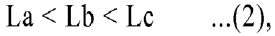
first block 9A, thesecond block 9B and thethird block 9c, respectively. - By satisfying the relation (2), a circumferential length of a
middle block 9 located on the side of the tire equator C is set larger than that of themiddle block 9 which is located on the side of the outboard tread edge To of the concernedmiddle block 9. Thus, the rigidity of the middle blocks 9 may also be enhanced in order toward the tire equator C, thereby improving the wear resistance of the middle blocks 9 by uniformizing these wear amount while ensuring a sufficient groove volume for traction. In order to further improve the advantageous effects, the ratios Lb/La and Lc/Lb of lengths of the middle blocks 9A to 9C are preferably in a range of more than 1.0 and not more than 1.15. More preferably, the maximal length Ls of thethird block 9C is in a range of from 15% to 25% the tread width TW. - The
tread portion 2 further includes a plurality of inboard shoulder blocks 11, a plurality of first inboard middle blocks 12 and a plurality of second inboard middle blocks 13. - The inboard shoulder blocks 11 each are defined by the
main groove 5, the inboard tread edge Ti and adjacent secondlateral grooves 7. In this embodiment, the inboard shoulder blocks 11 are configured as a circumferential long rectangular shape. - The first inboard middle blocks 12 each are defined by circumferentially adjacent first
inclined grooves 3, one of the secondinclined grooves 4, one of the firstlateral grooves 6, one of the secondlateral grooves 7 and themain groove 5. In this embodiment, the first inboard middle blocks 12 are configured as a bent shape that includes anaxially extending portion 12A and aninclined portion 12B arranged axially inward of theaxially extending portion 12A. - The second inboard middle blocks 13, for example, each are configured as a trapezoidal shape which is defined by one of the first
inclined groove 3, one of the firstlateral grooves 6, one of the secondlateral grooves 7 and themain groove 5. - While the embodiments in accordance with the present invention have been described in detail, the present invention is not limited to the illustrated embodiments, but can be modified and carried out in various aspects.
- Test tires having a size 205/60R15 and a basic tread pattern illustrated in
FIG. 1 were manufactured based on details shown in Table 1. Then, wear resistance, traction, straight traveling stability and cornering performance of each test tire were tested. The common specifications of tires and test procedures are as follows. - Groove depths of first inclined grooves, second inclined grooves and main groove: 11.5 mm
- Groove depth of first and second lateral grooves: 11.5 mm
- Angles of first inclined groove α1: 40 deg.
- Each test tire was installed to a four-wheel drive vehicle having a displacement of 2,000 cc using a rim of 7Jx15 with an inner pressure of 210 kPa. Then, a test driver drove the vehicle on a dirt trial test course for 20 laps to evaluate traction, cornering performance and straight traveling performance of each test tire by his feeling. The results are indicated using a score of Ex. 1 being 100. The larger the value, the better the performance is. Note that a 10-point difference means a significant performance difference, and a 5-point difference means an obvious performance difference.
- The test vehicle was traveled on a dry asphalt test course for 10,000 km. After traveling, groove depths remaining of the first and second inclined grooves on the rear wheel were measured at eight positions in the circumferential direction of the tire. Then difference between the groove depth before traveling and the average remaining groove depth was calculated as a groove wear amount. The smaller the value, the better the performance is.
- The test results are shown in Table 1. From the test results, it has been confirmed that the example tires improved the respective performances in well balanced manner as compared with the reference tires. In another test using tires having different size, the same results have been confirmed.
Table 1 (1/2) Ref. 1 Ref. 2 Ex. 1 Ex. 2 Ex. 3 Ex. 4 Ex. 5 Ex. 6 Ex. 7 Ex. 8 Tread pattern FIG. 4 FIG. 5 FIG. 1 FIG. 3 FIG. 1 FIG. 1 FIG. 1 FIG. 1 FIG. 1 FIG. 1 Ratio S2/S1 1.0 1.2 1.2 0.9 1.1 1.4 1.6 1.2 1.2 1.2 Ratio S3/S2 1.0 1.2 1.2 0.9 1.1 1.4 1.6 1.2 1.2 1.2 Ratio L2/TW (%) 9 0 9 9 9 9 9 3 6 12 Ratio L3/TW (%) 13 65 55 55 55 55 55 55 55 55 Ratio L4/TW (%) -35 35 35 -35 35 35 35 35 35 35 Traction [Score] 95 97 100 97 100 100 98 98 100 100 Cornering performance [Score] 93 95 100 97 99 99 98 97 98 100 Straight traveling performance [Score] 93 95 100 97 99 99 98 98 100 98 Wear resistance [mm] 2.4 3.5 2.0 2.4 2.0 2.0 2.2 2.5 2.2 2.0 Table 1 (2/2) Ex. 9 Ex. 10 Ex. 11 Ex. 12 Ex. 13 Ex. 14 Ex. 15 Ex. 16 Ex. 17 Tread pattern FIG. 1 FIG. 1 FIG. 1 FIG. 1 FIG. 1 FIG. 1 FIG. 1 FIG. 1 FIG. 1 Ratio S2/S1 1.2 1.2 1.2 1.2 1.2 1.2 1.2 1.2 1.2 Ratio S3/S2 1.2 1.2 1.2 1.2 1.2 1.2 1.2 1.2 1.2 Ratio L2/TW (%) 18 9 9 9 9 9 9 9 9 Ratio L3/TW (%) 55 45 50 65 70 55 55 55 55 Ratio L4/TW (%) 35 35 35 35 35 3 10 45 65 Traction [Score] 97 98 100 100 98 97 100 100 98 Cornering performance [Score] 98 97 98 100 100 97 100 100 98 Straight traveling performance [Score] 97 98 100 98 98 98 100 100 97 Wear resistance [mm] 2.0 2.0 2.0 2.0 2.1 2.1 2.0 2.0 2.1
Claims (7)
- A tire comprising:a tread portion having an installing direction to a vehicle, the tread portion having an outboard tread edge and an inboard tread edge;the tread portion being provided with a plurality of first inclined grooves each having an inclination with respect to a circumferential direction of the tire and extending from at least a tire equator to the outboard tread edge, a plurality of second inclined grooves each having an opposite inclination to the inclination of the first inclined grooves and extending from at least the tire equator toward the outboard tread edge, and a plurality of blocks separated by the first inclined grooves and the second inclined grooves; andeach second inclined groove comprising an outboard end that terminates at one of the first inclined grooves so that a plurality of substantially trapezoidal shoulder blocks are arranged along the outboard tread edge.
- The tire according to claim 1,
wherein the tread portion has a designated rotational direction, and the second inclined grooves are inclined forward in the rotational direction from the tire equator toward the outboard tread edge. - The tire according to claim 2,
wherein each of the second inclined grooves extends in an arc shape that protrudes backwardly in the rotational direction. - The tire according to any one of claims 1-3,
wherein each of the first inclined grooves is inclined at an angle of from 30 to 45 degrees with respect to the circumferential direction of the tire. - The tire according to any one of claims 1-4,
wherein the tread portion, in order toward the inboard tread edge, further comprises a first blocks, a second block and a third block, and the first block, the second block and the third block satisfy the following relation:
- The tire according to any one of claims 1-5,
wherein in a development view of the tread portion, each of the second inclined grooves is curved in an arc shape having a radius of curvature, and the center of the curvature is located on the side of the inboard tread edge with respect to the tire equator. - The tire according to any one of claims 1-6,
wherein each of the second inclined grooves extends continuously and smoothly between the outboard end and an inboard end.
Applications Claiming Priority (1)
| Application Number | Priority Date | Filing Date | Title |
|---|---|---|---|
| JP2015076772A JP6397363B2 (en) | 2015-04-03 | 2015-04-03 | tire |
Publications (3)
| Publication Number | Publication Date |
|---|---|
| EP3075571A2 true EP3075571A2 (en) | 2016-10-05 |
| EP3075571A3 EP3075571A3 (en) | 2016-11-02 |
| EP3075571B1 EP3075571B1 (en) | 2020-01-15 |
Family
ID=55527459
Family Applications (1)
| Application Number | Title | Priority Date | Filing Date |
|---|---|---|---|
| EP16160074.7A Active EP3075571B1 (en) | 2015-04-03 | 2016-03-14 | Tire |
Country Status (5)
| Country | Link |
|---|---|
| US (1) | US10195906B2 (en) |
| EP (1) | EP3075571B1 (en) |
| JP (1) | JP6397363B2 (en) |
| CN (1) | CN106042781B (en) |
| AU (1) | AU2016201516B2 (en) |
Cited By (1)
| Publication number | Priority date | Publication date | Assignee | Title |
|---|---|---|---|---|
| EP3517322A1 (en) * | 2018-01-29 | 2019-07-31 | Sumitomo Rubber Industries, Ltd. | Tire |
Families Citing this family (2)
| Publication number | Priority date | Publication date | Assignee | Title |
|---|---|---|---|---|
| JP6844244B2 (en) * | 2016-12-20 | 2021-03-17 | 横浜ゴム株式会社 | Pneumatic tires |
| JP7321053B2 (en) | 2019-10-17 | 2023-08-04 | Toyo Tire株式会社 | non-pneumatic tires |
Citations (1)
| Publication number | Priority date | Publication date | Assignee | Title |
|---|---|---|---|---|
| JP2011093391A (en) | 2009-10-28 | 2011-05-12 | Sumitomo Rubber Ind Ltd | Pneumatic tire |
Family Cites Families (13)
| Publication number | Priority date | Publication date | Assignee | Title |
|---|---|---|---|---|
| IT1250624B (en) * | 1991-07-04 | 1995-04-21 | Pirelli | RADIAL TIRE WITH SUB-CIRCUMFERENTIAL LONGITUDINAL SOCKETS. |
| JP3636768B2 (en) * | 1995-06-05 | 2005-04-06 | 株式会社ブリヂストン | Pneumatic tire |
| GB9720915D0 (en) * | 1997-10-03 | 1997-12-03 | Sumitomo Rubber Ind | Vehicle tyre |
| JP3365734B2 (en) * | 1998-01-09 | 2003-01-14 | オーツタイヤ株式会社 | Pneumatic radial tire |
| JP2002316516A (en) * | 2001-04-24 | 2002-10-29 | Yokohama Rubber Co Ltd:The | Pneumatic tire |
| JP4244056B2 (en) * | 2006-08-07 | 2009-03-25 | 横浜ゴム株式会社 | Pneumatic tire |
| JP5092309B2 (en) * | 2006-08-07 | 2012-12-05 | 横浜ゴム株式会社 | Pneumatic tire |
| US8281829B2 (en) * | 2007-10-25 | 2012-10-09 | Continental Tire The Americas Llc | Off-road tire tread having strake and chamfer structure |
| JP4705671B2 (en) * | 2008-12-12 | 2011-06-22 | 住友ゴム工業株式会社 | Pneumatic tire |
| US20110009464A1 (en) * | 2009-07-09 | 2011-01-13 | Light Sciences Oncology, Inc. | Immune system stimulation by light therapy induced apoptotic cell death in abnormal tissue |
| JP4966361B2 (en) * | 2009-10-28 | 2012-07-04 | 住友ゴム工業株式会社 | Pneumatic tire |
| JP5578296B1 (en) * | 2012-12-11 | 2014-08-27 | 横浜ゴム株式会社 | Pneumatic tire |
| JP6144983B2 (en) * | 2013-07-16 | 2017-06-07 | 東洋ゴム工業株式会社 | Pneumatic tire |
-
2015
- 2015-04-03 JP JP2015076772A patent/JP6397363B2/en active Active
-
2016
- 2016-03-09 AU AU2016201516A patent/AU2016201516B2/en active Active
- 2016-03-10 US US15/066,161 patent/US10195906B2/en active Active
- 2016-03-14 EP EP16160074.7A patent/EP3075571B1/en active Active
- 2016-03-28 CN CN201610181916.0A patent/CN106042781B/en active Active
Patent Citations (1)
| Publication number | Priority date | Publication date | Assignee | Title |
|---|---|---|---|---|
| JP2011093391A (en) | 2009-10-28 | 2011-05-12 | Sumitomo Rubber Ind Ltd | Pneumatic tire |
Cited By (1)
| Publication number | Priority date | Publication date | Assignee | Title |
|---|---|---|---|---|
| EP3517322A1 (en) * | 2018-01-29 | 2019-07-31 | Sumitomo Rubber Industries, Ltd. | Tire |
Also Published As
| Publication number | Publication date |
|---|---|
| JP6397363B2 (en) | 2018-09-26 |
| JP2016196237A (en) | 2016-11-24 |
| US10195906B2 (en) | 2019-02-05 |
| EP3075571B1 (en) | 2020-01-15 |
| AU2016201516A1 (en) | 2016-10-20 |
| EP3075571A3 (en) | 2016-11-02 |
| CN106042781B (en) | 2020-09-08 |
| CN106042781A (en) | 2016-10-26 |
| US20160288581A1 (en) | 2016-10-06 |
| AU2016201516B2 (en) | 2019-12-05 |
Similar Documents
| Publication | Publication Date | Title |
|---|---|---|
| EP3189983B1 (en) | Pneumatic tire | |
| EP3260308B1 (en) | Tire | |
| EP3326840B1 (en) | Tire | |
| EP3153334B1 (en) | Tire | |
| EP3081393B1 (en) | Pneumatic tire | |
| EP3421263B1 (en) | Tire | |
| EP3040216B1 (en) | Pneumatic tire | |
| EP3213932B1 (en) | Tire | |
| EP3248810B1 (en) | Tire | |
| EP3444131B1 (en) | Tire | |
| EP2777950B1 (en) | Pneumatic tire | |
| EP3363656B1 (en) | Tire | |
| US9731560B2 (en) | Pneumatic tire | |
| EP3075571B1 (en) | Tire | |
| EP3409507B1 (en) | Tire | |
| EP3603991B1 (en) | Pneumatic tyre | |
| EP3970996B1 (en) | Tire | |
| EP2821257B1 (en) | Pneumatic tire | |
| EP3549793B1 (en) | Tyre |
Legal Events
| Date | Code | Title | Description |
|---|---|---|---|
| PUAI | Public reference made under article 153(3) epc to a published international application that has entered the european phase |
Free format text: ORIGINAL CODE: 0009012 |
|
| PUAL | Search report despatched |
Free format text: ORIGINAL CODE: 0009013 |
|
| AK | Designated contracting states |
Kind code of ref document: A2 Designated state(s): AL AT BE BG CH CY CZ DE DK EE ES FI FR GB GR HR HU IE IS IT LI LT LU LV MC MK MT NL NO PL PT RO RS SE SI SK SM TR |
|
| AX | Request for extension of the european patent |
Extension state: BA ME |
|
| AK | Designated contracting states |
Kind code of ref document: A3 Designated state(s): AL AT BE BG CH CY CZ DE DK EE ES FI FR GB GR HR HU IE IS IT LI LT LU LV MC MK MT NL NO PL PT RO RS SE SI SK SM TR |
|
| AX | Request for extension of the european patent |
Extension state: BA ME |
|
| RIC1 | Information provided on ipc code assigned before grant |
Ipc: B60C 11/11 20060101ALI20160926BHEP Ipc: B60C 11/03 20060101AFI20160926BHEP |
|
| STAA | Information on the status of an ep patent application or granted ep patent |
Free format text: STATUS: REQUEST FOR EXAMINATION WAS MADE |
|
| 17P | Request for examination filed |
Effective date: 20170322 |
|
| RBV | Designated contracting states (corrected) |
Designated state(s): AL AT BE BG CH CY CZ DE DK EE ES FI FR GB GR HR HU IE IS IT LI LT LU LV MC MK MT NL NO PL PT RO RS SE SI SK SM TR |
|
| GRAP | Despatch of communication of intention to grant a patent |
Free format text: ORIGINAL CODE: EPIDOSNIGR1 |
|
| STAA | Information on the status of an ep patent application or granted ep patent |
Free format text: STATUS: GRANT OF PATENT IS INTENDED |
|
| INTG | Intention to grant announced |
Effective date: 20191010 |
|
| GRAS | Grant fee paid |
Free format text: ORIGINAL CODE: EPIDOSNIGR3 |
|
| GRAA | (expected) grant |
Free format text: ORIGINAL CODE: 0009210 |
|
| STAA | Information on the status of an ep patent application or granted ep patent |
Free format text: STATUS: THE PATENT HAS BEEN GRANTED |
|
| AK | Designated contracting states |
Kind code of ref document: B1 Designated state(s): AL AT BE BG CH CY CZ DE DK EE ES FI FR GB GR HR HU IE IS IT LI LT LU LV MC MK MT NL NO PL PT RO RS SE SI SK SM TR |
|
| REG | Reference to a national code |
Ref country code: CH Ref legal event code: EP Ref country code: GB Ref legal event code: FG4D |
|
| REG | Reference to a national code |
Ref country code: IE Ref legal event code: FG4D |
|
| REG | Reference to a national code |
Ref country code: DE Ref legal event code: R096 Ref document number: 602016028156 Country of ref document: DE |
|
| REG | Reference to a national code |
Ref country code: AT Ref legal event code: REF Ref document number: 1224831 Country of ref document: AT Kind code of ref document: T Effective date: 20200215 |
|
| REG | Reference to a national code |
Ref country code: NL Ref legal event code: MP Effective date: 20200115 |
|
| REG | Reference to a national code |
Ref country code: LT Ref legal event code: MG4D |
|
| PG25 | Lapsed in a contracting state [announced via postgrant information from national office to epo] |
Ref country code: RS Free format text: LAPSE BECAUSE OF FAILURE TO SUBMIT A TRANSLATION OF THE DESCRIPTION OR TO PAY THE FEE WITHIN THE PRESCRIBED TIME-LIMIT Effective date: 20200115 Ref country code: FI Free format text: LAPSE BECAUSE OF FAILURE TO SUBMIT A TRANSLATION OF THE DESCRIPTION OR TO PAY THE FEE WITHIN THE PRESCRIBED TIME-LIMIT Effective date: 20200115 Ref country code: NO Free format text: LAPSE BECAUSE OF FAILURE TO SUBMIT A TRANSLATION OF THE DESCRIPTION OR TO PAY THE FEE WITHIN THE PRESCRIBED TIME-LIMIT Effective date: 20200415 Ref country code: NL Free format text: LAPSE BECAUSE OF FAILURE TO SUBMIT A TRANSLATION OF THE DESCRIPTION OR TO PAY THE FEE WITHIN THE PRESCRIBED TIME-LIMIT Effective date: 20200115 Ref country code: PT Free format text: LAPSE BECAUSE OF FAILURE TO SUBMIT A TRANSLATION OF THE DESCRIPTION OR TO PAY THE FEE WITHIN THE PRESCRIBED TIME-LIMIT Effective date: 20200607 |
|
| PG25 | Lapsed in a contracting state [announced via postgrant information from national office to epo] |
Ref country code: HR Free format text: LAPSE BECAUSE OF FAILURE TO SUBMIT A TRANSLATION OF THE DESCRIPTION OR TO PAY THE FEE WITHIN THE PRESCRIBED TIME-LIMIT Effective date: 20200115 Ref country code: GR Free format text: LAPSE BECAUSE OF FAILURE TO SUBMIT A TRANSLATION OF THE DESCRIPTION OR TO PAY THE FEE WITHIN THE PRESCRIBED TIME-LIMIT Effective date: 20200416 Ref country code: LV Free format text: LAPSE BECAUSE OF FAILURE TO SUBMIT A TRANSLATION OF THE DESCRIPTION OR TO PAY THE FEE WITHIN THE PRESCRIBED TIME-LIMIT Effective date: 20200115 Ref country code: SE Free format text: LAPSE BECAUSE OF FAILURE TO SUBMIT A TRANSLATION OF THE DESCRIPTION OR TO PAY THE FEE WITHIN THE PRESCRIBED TIME-LIMIT Effective date: 20200115 Ref country code: IS Free format text: LAPSE BECAUSE OF FAILURE TO SUBMIT A TRANSLATION OF THE DESCRIPTION OR TO PAY THE FEE WITHIN THE PRESCRIBED TIME-LIMIT Effective date: 20200515 Ref country code: BG Free format text: LAPSE BECAUSE OF FAILURE TO SUBMIT A TRANSLATION OF THE DESCRIPTION OR TO PAY THE FEE WITHIN THE PRESCRIBED TIME-LIMIT Effective date: 20200415 |
|
| REG | Reference to a national code |
Ref country code: DE Ref legal event code: R097 Ref document number: 602016028156 Country of ref document: DE |
|
| PG25 | Lapsed in a contracting state [announced via postgrant information from national office to epo] |
Ref country code: SK Free format text: LAPSE BECAUSE OF FAILURE TO SUBMIT A TRANSLATION OF THE DESCRIPTION OR TO PAY THE FEE WITHIN THE PRESCRIBED TIME-LIMIT Effective date: 20200115 Ref country code: CZ Free format text: LAPSE BECAUSE OF FAILURE TO SUBMIT A TRANSLATION OF THE DESCRIPTION OR TO PAY THE FEE WITHIN THE PRESCRIBED TIME-LIMIT Effective date: 20200115 Ref country code: RO Free format text: LAPSE BECAUSE OF FAILURE TO SUBMIT A TRANSLATION OF THE DESCRIPTION OR TO PAY THE FEE WITHIN THE PRESCRIBED TIME-LIMIT Effective date: 20200115 Ref country code: LT Free format text: LAPSE BECAUSE OF FAILURE TO SUBMIT A TRANSLATION OF THE DESCRIPTION OR TO PAY THE FEE WITHIN THE PRESCRIBED TIME-LIMIT Effective date: 20200115 Ref country code: ES Free format text: LAPSE BECAUSE OF FAILURE TO SUBMIT A TRANSLATION OF THE DESCRIPTION OR TO PAY THE FEE WITHIN THE PRESCRIBED TIME-LIMIT Effective date: 20200115 Ref country code: DK Free format text: LAPSE BECAUSE OF FAILURE TO SUBMIT A TRANSLATION OF THE DESCRIPTION OR TO PAY THE FEE WITHIN THE PRESCRIBED TIME-LIMIT Effective date: 20200115 Ref country code: MC Free format text: LAPSE BECAUSE OF FAILURE TO SUBMIT A TRANSLATION OF THE DESCRIPTION OR TO PAY THE FEE WITHIN THE PRESCRIBED TIME-LIMIT Effective date: 20200115 Ref country code: SM Free format text: LAPSE BECAUSE OF FAILURE TO SUBMIT A TRANSLATION OF THE DESCRIPTION OR TO PAY THE FEE WITHIN THE PRESCRIBED TIME-LIMIT Effective date: 20200115 Ref country code: EE Free format text: LAPSE BECAUSE OF FAILURE TO SUBMIT A TRANSLATION OF THE DESCRIPTION OR TO PAY THE FEE WITHIN THE PRESCRIBED TIME-LIMIT Effective date: 20200115 |
|
| REG | Reference to a national code |
Ref country code: CH Ref legal event code: PL |
|
| REG | Reference to a national code |
Ref country code: AT Ref legal event code: MK05 Ref document number: 1224831 Country of ref document: AT Kind code of ref document: T Effective date: 20200115 |
|
| PLBE | No opposition filed within time limit |
Free format text: ORIGINAL CODE: 0009261 |
|
| STAA | Information on the status of an ep patent application or granted ep patent |
Free format text: STATUS: NO OPPOSITION FILED WITHIN TIME LIMIT |
|
| 26N | No opposition filed |
Effective date: 20201016 |
|
| REG | Reference to a national code |
Ref country code: BE Ref legal event code: MM Effective date: 20200331 |
|
| PG25 | Lapsed in a contracting state [announced via postgrant information from national office to epo] |
Ref country code: LU Free format text: LAPSE BECAUSE OF NON-PAYMENT OF DUE FEES Effective date: 20200314 |
|
| PG25 | Lapsed in a contracting state [announced via postgrant information from national office to epo] |
Ref country code: LI Free format text: LAPSE BECAUSE OF NON-PAYMENT OF DUE FEES Effective date: 20200331 Ref country code: CH Free format text: LAPSE BECAUSE OF NON-PAYMENT OF DUE FEES Effective date: 20200331 Ref country code: IT Free format text: LAPSE BECAUSE OF FAILURE TO SUBMIT A TRANSLATION OF THE DESCRIPTION OR TO PAY THE FEE WITHIN THE PRESCRIBED TIME-LIMIT Effective date: 20200115 Ref country code: IE Free format text: LAPSE BECAUSE OF NON-PAYMENT OF DUE FEES Effective date: 20200314 Ref country code: AT Free format text: LAPSE BECAUSE OF FAILURE TO SUBMIT A TRANSLATION OF THE DESCRIPTION OR TO PAY THE FEE WITHIN THE PRESCRIBED TIME-LIMIT Effective date: 20200115 |
|
| PG25 | Lapsed in a contracting state [announced via postgrant information from national office to epo] |
Ref country code: SI Free format text: LAPSE BECAUSE OF FAILURE TO SUBMIT A TRANSLATION OF THE DESCRIPTION OR TO PAY THE FEE WITHIN THE PRESCRIBED TIME-LIMIT Effective date: 20200115 Ref country code: BE Free format text: LAPSE BECAUSE OF NON-PAYMENT OF DUE FEES Effective date: 20200331 Ref country code: PL Free format text: LAPSE BECAUSE OF FAILURE TO SUBMIT A TRANSLATION OF THE DESCRIPTION OR TO PAY THE FEE WITHIN THE PRESCRIBED TIME-LIMIT Effective date: 20200115 |
|
| GBPC | Gb: european patent ceased through non-payment of renewal fee |
Effective date: 20200415 |
|
| PG25 | Lapsed in a contracting state [announced via postgrant information from national office to epo] |
Ref country code: GB Free format text: LAPSE BECAUSE OF NON-PAYMENT OF DUE FEES Effective date: 20200415 |
|
| PG25 | Lapsed in a contracting state [announced via postgrant information from national office to epo] |
Ref country code: TR Free format text: LAPSE BECAUSE OF FAILURE TO SUBMIT A TRANSLATION OF THE DESCRIPTION OR TO PAY THE FEE WITHIN THE PRESCRIBED TIME-LIMIT Effective date: 20200115 Ref country code: MT Free format text: LAPSE BECAUSE OF FAILURE TO SUBMIT A TRANSLATION OF THE DESCRIPTION OR TO PAY THE FEE WITHIN THE PRESCRIBED TIME-LIMIT Effective date: 20200115 Ref country code: CY Free format text: LAPSE BECAUSE OF FAILURE TO SUBMIT A TRANSLATION OF THE DESCRIPTION OR TO PAY THE FEE WITHIN THE PRESCRIBED TIME-LIMIT Effective date: 20200115 |
|
| PG25 | Lapsed in a contracting state [announced via postgrant information from national office to epo] |
Ref country code: MK Free format text: LAPSE BECAUSE OF FAILURE TO SUBMIT A TRANSLATION OF THE DESCRIPTION OR TO PAY THE FEE WITHIN THE PRESCRIBED TIME-LIMIT Effective date: 20200115 Ref country code: AL Free format text: LAPSE BECAUSE OF FAILURE TO SUBMIT A TRANSLATION OF THE DESCRIPTION OR TO PAY THE FEE WITHIN THE PRESCRIBED TIME-LIMIT Effective date: 20200115 |
|
| PGFP | Annual fee paid to national office [announced via postgrant information from national office to epo] |
Ref country code: FR Payment date: 20230208 Year of fee payment: 8 |
|
| PGFP | Annual fee paid to national office [announced via postgrant information from national office to epo] |
Ref country code: DE Payment date: 20230131 Year of fee payment: 8 |
|
| P01 | Opt-out of the competence of the unified patent court (upc) registered |
Effective date: 20230510 |