EP1568463B1 - Elément d'outil avec pièce d'outil associée pour une entrée d'injection d'une buse à canal chaud pour une machine à mouler par injection - Google Patents
Elément d'outil avec pièce d'outil associée pour une entrée d'injection d'une buse à canal chaud pour une machine à mouler par injection Download PDFInfo
- Publication number
- EP1568463B1 EP1568463B1 EP05002867A EP05002867A EP1568463B1 EP 1568463 B1 EP1568463 B1 EP 1568463B1 EP 05002867 A EP05002867 A EP 05002867A EP 05002867 A EP05002867 A EP 05002867A EP 1568463 B1 EP1568463 B1 EP 1568463B1
- Authority
- EP
- European Patent Office
- Prior art keywords
- tool
- insert
- tool insert
- bore
- reception
- Prior art date
- Legal status (The legal status is an assumption and is not a legal conclusion. Google has not performed a legal analysis and makes no representation as to the accuracy of the status listed.)
- Expired - Lifetime
Links
- 238000001746 injection moulding Methods 0.000 title claims abstract description 8
- 238000005520 cutting process Methods 0.000 claims abstract description 13
- 238000003780 insertion Methods 0.000 abstract description 4
- 230000037431 insertion Effects 0.000 abstract description 4
- 239000000243 solution Substances 0.000 description 15
- 238000002347 injection Methods 0.000 description 6
- 239000007924 injection Substances 0.000 description 6
- 238000000926 separation method Methods 0.000 description 6
- 239000000155 melt Substances 0.000 description 3
- 238000010438 heat treatment Methods 0.000 description 2
- 238000004519 manufacturing process Methods 0.000 description 2
- 239000004020 conductor Substances 0.000 description 1
- 230000001419 dependent effect Effects 0.000 description 1
- 210000004907 gland Anatomy 0.000 description 1
- 239000012943 hotmelt Substances 0.000 description 1
- 239000011810 insulating material Substances 0.000 description 1
- 230000003993 interaction Effects 0.000 description 1
- 230000001788 irregular Effects 0.000 description 1
- 239000007788 liquid Substances 0.000 description 1
- 239000000463 material Substances 0.000 description 1
- 238000000034 method Methods 0.000 description 1
- 230000035515 penetration Effects 0.000 description 1
- 230000000717 retained effect Effects 0.000 description 1
- 230000008646 thermal stress Effects 0.000 description 1
- 230000007704 transition Effects 0.000 description 1
Images
Classifications
-
- B—PERFORMING OPERATIONS; TRANSPORTING
- B29—WORKING OF PLASTICS; WORKING OF SUBSTANCES IN A PLASTIC STATE IN GENERAL
- B29C—SHAPING OR JOINING OF PLASTICS; SHAPING OF MATERIAL IN A PLASTIC STATE, NOT OTHERWISE PROVIDED FOR; AFTER-TREATMENT OF THE SHAPED PRODUCTS, e.g. REPAIRING
- B29C45/00—Injection moulding, i.e. forcing the required volume of moulding material through a nozzle into a closed mould; Apparatus therefor
- B29C45/17—Component parts, details or accessories; Auxiliary operations
- B29C45/26—Moulds
- B29C45/27—Sprue channels ; Runner channels or runner nozzles
- B29C45/2701—Details not specific to hot or cold runner channels
- B29C45/2708—Gates
- B29C45/2711—Gate inserts
-
- B—PERFORMING OPERATIONS; TRANSPORTING
- B29—WORKING OF PLASTICS; WORKING OF SUBSTANCES IN A PLASTIC STATE IN GENERAL
- B29C—SHAPING OR JOINING OF PLASTICS; SHAPING OF MATERIAL IN A PLASTIC STATE, NOT OTHERWISE PROVIDED FOR; AFTER-TREATMENT OF THE SHAPED PRODUCTS, e.g. REPAIRING
- B29C45/00—Injection moulding, i.e. forcing the required volume of moulding material through a nozzle into a closed mould; Apparatus therefor
- B29C45/17—Component parts, details or accessories; Auxiliary operations
- B29C45/26—Moulds
- B29C45/27—Sprue channels ; Runner channels or runner nozzles
- B29C45/278—Nozzle tips
Definitions
- the present invention relates to a tool insert with associated tool part for the gate of a hot runner nozzle for an injection molding machine according to the preamble of claim 1.
- hot melt is injected from an injection molding machine either directly or via a hot runner manifold system by means of a hot runner nozzle in the mold (injection mold).
- the tool consists of a hot runner nozzle receiving the injection side, in which usually the outer shape (cavity) of the plastic part is located, and an ejector with the inner shape (core).
- the area in which the hot runner nozzle adjoins the tool and the plastic part is referred to as "gate”.
- the front, tool-side part of the hot runner nozzle with the gate area is in injection molding in a recess of the tool.
- the nozzle In the rear area, the nozzle is supported axially on the hot runner manifold block and is fixed with the front gate part by means of a precision seal in the tool. There, the nozzle is exposed to strong mechanical and thermal stresses. Because the bleed area The nozzle is therefore subject to rapid wear, it is not designed as an integral part of the hot runner nozzle, but as a replaceable tool insert.
- connection of the tool insert to the nozzle and to the tool can be designed in different ways. Depending on the solution, the scope of work for the toolmaker is different. In addition, the necessary thermal separation between nozzle and tool plays an important role in these solutions. After completion of the actual injection process, the melt injected into the mold should solidify rapidly, while the melt retained in the nozzle tip should remain liquid. This means that between the two areas mentioned a temperature difference of about 200 ° C must be achieved.
- a known design of the tool insert is that it can be screwed into the front (tool-side) end of the nozzle.
- This solution requires the least effort from the toolmaker. He only needs to introduce the nozzle bore dimensions in the tool and provide a fitting hole for the gate area.
- the disadvantage of this solution is firstly that by the screwing of the tool insert with the nozzle an undesirable good heat conduction from the nozzle shaft to the front of the tool insert takes place.
- Another disadvantage of this solution is that by the heating of the hot runner manifold block, in which the nozzle shafts are screwed, and by the heating of the nozzle thermal position changes acting on the nozzle, which the exact position of the nozzles and screwed with her tool inserts with respect to negatively affect the tool.
- a third disadvantage is when the frontal contact surface between the tool insert and the cavity of the tool is not rotationally symmetrical, but for example is formed obliquely.
- the nozzle must be introduced with the tool insert in a precise rotational angular position about its longitudinal axis in the fitting bore of the tool. This is with reference to the required fixed screw between tool insert and nozzle on the one hand and nozzle stem and hot runner manifold block on the other hand practically impossible to reach when reassembling after disassembly with the same gland torque.
- the nozzle with its nozzle tip consists of a good heat-conducting material.
- a cap is screwed, into which protrudes the nozzle tip.
- a member of insulating material for example by means of screwing, is inserted between the nozzle tip and the nozzle cap. The contact with the tool is only a small cylindrical surface at the front end of the tool cap.
- a second known solution is to incorporate the gate area directly into the tool instead of a separate tool insert. In this case, the positioning and the thermal separation can be realized in a good manner.
- the disadvantage of this solution is the high production costs for the toolmaker. This must be incorporated in the tool hemisphere surfaces, conical surfaces, heels and different fits.
- Another disadvantage of this solution is that when wear of the gate, the entire injection side of the tool or individual cavities must be replaced or repaired.
- a third known solution of the work of the tool maker compared to said second solution is reduced by the gate is made by a tool insert in the tool.
- the thermal separation is good, and a certain angular position can be achieved by a rotation lock. If worn, the tool insert can easily be replaced with a new tool insert.
- the workload for the toolmaker is also greater in this solution than in the former solution.
- the present invention has for its object to develop a tool insert of the type mentioned, which is such that the toolmaker on Tool to be made connection work is simple and low, that a good thermal separation between tool insert and tool is achieved and, where necessary, a predetermined angular position of the tool insert is easily adjustable in an exact manner and this is easily reproducible even when re-inserting the tool insert.
- the tool insert according to the invention not only combines the advantages of the above-mentioned three known solutions, but goes even further.
- the toolmaker only needs to drill two holes and a fit into the tool. They cover all work for the nozzle and the tool insert.
- the thermal separation is optimal, and the tool insert can be removed if necessary and reinstalled in exactly the same angular position or replaced by another tool insert. If, for some reason, the same or a different tool insert is to be installed in a different rotational angle position, then additional guide grooves can be cut when inserting the tool insert into the inner surface of the receiving bore of the tool.
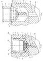
- 20 denotes a section of the injection side of the tool.
- 20a denotes the wall of the injection side of the tool and 20b the cavity.
- the tool insert 10 consists of a cylindrical fitting part 11 with flow channel 11a for the melt and a receiving head 12 for receiving the nozzle indicated by dashed lines 30.
- a recess 21 which consists of a fitting bore 24 ( Figure 2) for receiving the fitting part eleventh and a receiving bore 22 for receiving the receiving head 12 of the tool insert is.
- the seal between the nozzle 30 and tool insert via the designated in Figure 1 with b cylindrical surfaces of nozzle 30 and tool insert 10th
- the illustrated embodiment of the tool insert is provided on its in itself cylindrical outer surface 12 a of the receiving head 12 with a regular hexagon 17.
- the diameter of this hexagon between two diametrically opposite corners of the hexagon is slightly larger than the diameter of the receiving bore 22 of the tool. This means that the first insertion of the tool insert into the tool recess 21, the extending in the longitudinal direction of the nozzle corner edges of the hexagon penetrate into the material of the tool and this guide grooves 15 in the wall 16 of the receiving bore 22 cut or clear.
- To accommodate the resulting chips shaved recesses 13 in the corner regions of the hexagon 17 are provided at the axial upper and lower end of the hexagon. Will after its dismantling such Tool insert inserted again or replaced with a new one, so the required rotational angle position is exactly predetermined by the already cut guide grooves 15.
- the axial end position of the tool insert in the tool is determined by the interaction of a flange 18 at the end of the tool insert averted from the tool and by the depth of a correspondingly sized, expanding paragraph 28 at the entrance of the tool recess 21.
- This end position is chosen so that when edition the flange 18 on the enlarged shoulder 28 a certain distance a ( Figure 1) between the frontal region 19 of the tool insert and the bottom 29 of the receiving bore 22 is present.
- the seat between the fitting part 11 and the associated receiving bore 24 of the tool is so strong that after the penetration of the fitting part 11 into the receiving bore 24 a turning of the tool insert is no longer possible.
- the tool insert must be positioned in the tool recess 21 in a defined angular position.
- the axial position of the hex 17 on the tool insert is selected so that at the beginning of the cutting process, ie when the insertion of the tool insert into the tool recess 21 of the hex 17 reaches the bottom of the paragraph 28, the fitting part 11 is not yet has penetrated into the associated receiving bore 24.
- This Einschiebeaugenblick is shown in Figure 2.
- the tool insert can be rotated without difficulty in the desired angular position. Thereafter, the impressions and the cutting of the guide grooves 15 takes place.
- the regular hexagon 17 shown in the figures may be replaced by any other regular or irregular polygon.
- the inventive idea is already realized by a single cuttable projection formed on the outer circumferential surface 12a of the receiving head 12, which has an extent in the radial direction, which is greater than the radius of the receiving bore 22 in the tool 20 so that it when inserting of the tool insert 10 in the tool recess 21 is able to cut a guide groove 15 in the inner surface 16 of the receiving bore 22.
- cuttable projections 14 are present, they are preferably distributed uniformly over the circumference of the receiving head 12.
Landscapes
- Engineering & Computer Science (AREA)
- Manufacturing & Machinery (AREA)
- Mechanical Engineering (AREA)
- Moulds For Moulding Plastics Or The Like (AREA)
- Injection Moulding Of Plastics Or The Like (AREA)
Claims (7)
- Élément insérable d'outil pourvu d'une partie d'outil correspondante, lequel élément insérable d'outil (10) est destiné à l'entrée d'une buse de canal chaud pour une machine à injecter et se raccorde à la partie antérieure de la buse de canal chaud et peut pour sa part être inséré dans une cavité (21) correspondante de l'outil (20), caractérisé
en ce que l'élément insérable d'outil (10) comprend une pièce d'ajustage (11) cylindrique, avant, munie d'un canal de coulée (11a) et une tête de réception (12) de la buse (30),
en ce que, sur le côté latéral (22a) extérieur en soi cylindrique, la tête de réception (12) est munie d'au moins une saillie (14) capable de couper, dont l'étendue en direction radiale est supérieure au rayon du perçage de réception (22) prévu dans l'outil (20) pour recevoir la tête de réception (12) de l'élément insérable d'outil (10) et en ce que la saillie (14) capable de couper est conçue de telle manière que, quand on insère l'élément insérable d'outil (10) dans ledit perçage de réception (22) de l'outil, elle puisse couper une rainure de guidage (15) dans la surface intérieure (16) du perçage de réception (22) dans l'outil. - Élément insérable d'outil pourvu d'une pièce d'outil correspondante selon la revendication 1, caractérisé en ce que plusieurs saillies (14) capables de couper sont réparties régulièrement sur le pourtour de la tête de réception (12).
- Élément insérable d'outil pourvu d'une pièce d'outil correspondante selon l'une des revendications 1 ou 2, caractérisé en ce que plusieurs saillies (14) capables de couper sont formées du fait qu'un segment axial de la tête de réception (12) est un polygone (17), l'étendue radiale des sommets du polygone (17) étant supérieure au rayon du perçage de réception (22) prévu dans l'outil (20) pour recevoir la tête de réception (12) de l'élément insérable d'outil (10), et en ce que les bords axiaux du polygone forment lesdites saillies (14) capables de couper.
- Élément insérable d'outil pourvu d'une pièce d'outil correspondante selon la revendication 3, caractérisé en ce que le polygone (17) est un hexagone régulier.
- Élément insérable d'outil pourvu d'une pièce d'outil correspondante selon l'une des revendications précédentes, caractérisé en ce que la position axiale des saillies (14) capables de couper est choisie de telle manière que, quand on insère l'élément insérable d'outil (10) dans le perçage de réception (22) pour la tête de réception (12) de l'élément insérable d'outil (10), l'opération de coupe commence avant que la pièce d'ajustage (11) cylindrique ne pénètre dans le perçage de réception (24) correspondant dans l'outil (20).
- Élément insérable d'outil pourvu d'une pièce d'outil correspondante selon l'une des revendications précédentes, caractérisé en ce que la position axiale finale de l'élément insérable d'outil (10) dans la cavité (21) de l'outil est déterminée du fait qu'une collerette (18) à l'extrémité - détournée de l'outil - de l'élément insérable d'outil (10) coopère avec un épaulement (28) élargi correspondant de l'entrée de la cavité (21) de l'outil.
- Élément insérable d'outil pourvu d'une pièce d'outil correspondante selon la revendication 6, caractérisé en ce que la position finale axiale est choisie de telle manière que la zone (19) frontale - orientée vers l'outil - de la tête de réception (12) ne touche pas (intervalle a) le fond (29) du perçage de réception (22).
Priority Applications (1)
| Application Number | Priority Date | Filing Date | Title |
|---|---|---|---|
| PL05002867T PL1568463T3 (pl) | 2004-02-28 | 2005-02-11 | Wkładka narzędziowa z przynależną częścią narzędzia do otworu wtryskowego dyszy gorącokanałowej dla wtryskarki |
Applications Claiming Priority (2)
| Application Number | Priority Date | Filing Date | Title |
|---|---|---|---|
| DE102004009799 | 2004-02-28 | ||
| DE102004009799A DE102004009799B4 (de) | 2004-02-28 | 2004-02-28 | Werkzeugeinsatz für den Anschnitt einer Heißkanaldüse für eine Spritzgießmaschine |
Publications (2)
| Publication Number | Publication Date |
|---|---|
| EP1568463A1 EP1568463A1 (fr) | 2005-08-31 |
| EP1568463B1 true EP1568463B1 (fr) | 2007-03-21 |
Family
ID=34745314
Family Applications (1)
| Application Number | Title | Priority Date | Filing Date |
|---|---|---|---|
| EP05002867A Expired - Lifetime EP1568463B1 (fr) | 2004-02-28 | 2005-02-11 | Elément d'outil avec pièce d'outil associée pour une entrée d'injection d'une buse à canal chaud pour une machine à mouler par injection |
Country Status (7)
| Country | Link |
|---|---|
| US (1) | US7287976B2 (fr) |
| EP (1) | EP1568463B1 (fr) |
| AT (1) | ATE357326T1 (fr) |
| DE (2) | DE102004009799B4 (fr) |
| ES (1) | ES2284096T3 (fr) |
| PL (1) | PL1568463T3 (fr) |
| PT (1) | PT1568463E (fr) |
Families Citing this family (3)
| Publication number | Priority date | Publication date | Assignee | Title |
|---|---|---|---|---|
| US7370417B2 (en) * | 2005-12-09 | 2008-05-13 | Mold-Masters (2007) Limited | Method of installing a mold gate insert in an injection molding apparatus |
| CN101927554A (zh) * | 2009-06-26 | 2010-12-29 | 鸿富锦精密工业(深圳)有限公司 | 模具 |
| JP2024084388A (ja) * | 2022-12-13 | 2024-06-25 | セイコーエプソン株式会社 | 成形型、および射出成形装置の評価方法 |
Family Cites Families (13)
| Publication number | Priority date | Publication date | Assignee | Title |
|---|---|---|---|---|
| US2339443A (en) * | 1941-03-08 | 1944-01-18 | Armstrong Cork Co | Injection molding machine |
| US4666396A (en) * | 1982-11-22 | 1987-05-19 | Shaw Richard J | Thermally insulated heated sprue bushing in plastic molding apparatus |
| US4950154A (en) * | 1989-07-03 | 1990-08-21 | Moberg Clifford A | Combination injection mold and sprue bushing |
| JPH09174612A (ja) * | 1995-12-22 | 1997-07-08 | Victor Co Of Japan Ltd | Icカード用基材の射出成形方法及びその金型 |
| US5879727A (en) * | 1997-01-21 | 1999-03-09 | Husky Injection Molding Systems, Ltd. | Insulated modular injection nozzle system |
| US5895669A (en) * | 1997-06-13 | 1999-04-20 | Incoe Corporation | Injection molding shut-off bushing with separate material flow path |
| CA2262175C (fr) * | 1999-02-16 | 2008-02-12 | Mold-Masters Limited | Materiel de moulage par injection a joint de bec detachable |
| US6220850B1 (en) * | 1999-02-16 | 2001-04-24 | Husky Injection Molding Systems Ltd. | Mold gate insert |
| FR2795993B1 (fr) * | 1999-07-06 | 2001-09-28 | Delachaux Sa | Dispositif d'injection de matiere a l'etat plastique dans une empreinte de moulage |
| CA2286953A1 (fr) * | 1999-10-18 | 2001-04-18 | Helen Zhuang | Systeme d'injection |
| US6402502B1 (en) * | 2000-08-04 | 2002-06-11 | Richter Precision, Inc. | Thermally conductive hub bushing |
| WO2003086734A1 (fr) * | 2002-04-12 | 2003-10-23 | Mold-Masters Limited | Insert d'entrée de moule à barrière thermique |
| DE10354456B4 (de) * | 2002-11-21 | 2016-10-13 | Mold-Masters (2007) Limited | Düse mit einer Spitze, einem die Spitze umgebenden Teil und einem Positionierteil und Spritzgießvorrichtung mit der Düse |
-
2004
- 2004-02-28 DE DE102004009799A patent/DE102004009799B4/de not_active Expired - Fee Related
- 2004-11-22 US US10/904,663 patent/US7287976B2/en not_active Expired - Fee Related
-
2005
- 2005-02-11 ES ES05002867T patent/ES2284096T3/es not_active Expired - Lifetime
- 2005-02-11 AT AT05002867T patent/ATE357326T1/de not_active IP Right Cessation
- 2005-02-11 DE DE502005000482T patent/DE502005000482D1/de not_active Expired - Lifetime
- 2005-02-11 PL PL05002867T patent/PL1568463T3/pl unknown
- 2005-02-11 PT PT05002867T patent/PT1568463E/pt unknown
- 2005-02-11 EP EP05002867A patent/EP1568463B1/fr not_active Expired - Lifetime
Also Published As
| Publication number | Publication date |
|---|---|
| DE102004009799B4 (de) | 2006-03-23 |
| DE102004009799A1 (de) | 2005-09-15 |
| ES2284096T3 (es) | 2007-11-01 |
| PT1568463E (pt) | 2007-06-05 |
| US7287976B2 (en) | 2007-10-30 |
| PL1568463T3 (pl) | 2007-08-31 |
| DE502005000482D1 (de) | 2007-05-03 |
| ATE357326T1 (de) | 2007-04-15 |
| US20050191383A1 (en) | 2005-09-01 |
| EP1568463A1 (fr) | 2005-08-31 |
Similar Documents
| Publication | Publication Date | Title |
|---|---|---|
| DE10136293B4 (de) | Gewindeformer oder -bohrer | |
| DE102004021484B4 (de) | Verfahren zum Herstellen einer Verbindungsanordnung | |
| DE69729945T2 (de) | Fräser | |
| EP2318166B1 (fr) | Outil pour l'usinage par enlèvement de copeaux d'une pièce à usiner | |
| DE10012810A1 (de) | Wälzkörpergewindetrieb mit radial eingesetztem Umlenkelement | |
| EP2406029A1 (fr) | Outil d'enlèvement de copeaux pour une machine-outil | |
| EP1407848B1 (fr) | Outil de filetage avec refroidissement | |
| EP0891238B1 (fr) | Outil de percage pour machines-outils et procede permettant de la produire | |
| EP2954968A1 (fr) | Fraise de filetage | |
| WO2012117033A1 (fr) | Filière | |
| EP0930133A2 (fr) | Truelle avec poignée | |
| EP0800907B1 (fr) | Buse à fermeture par aiguille avec moule d'injection et aiguille de fermeture | |
| WO2009074217A2 (fr) | Ensemble composé d'une partie support et d'un insert fileté, procédé de fabrication de l'ensemble et dispositif de moulage par injection de l'insert fileté | |
| DE102017123786A1 (de) | Halter für ein Nutstoßwerkzeug | |
| EP1568463B1 (fr) | Elément d'outil avec pièce d'outil associée pour une entrée d'injection d'une buse à canal chaud pour une machine à mouler par injection | |
| EP1896207B1 (fr) | Système d'outillage avec interface | |
| EP2511067B1 (fr) | Chemise de refroidissement avec élément d'appui | |
| DE10024625B4 (de) | Formnest für die Kunststoffverarbeitung | |
| DE4127509C2 (fr) | ||
| DE202013101539U1 (de) | Abstandsjustierelement | |
| DE20111198U1 (de) | Kaliberplatte mit einem Einsatzteil für eine Formgebungseinrichtung | |
| WO1988009708A1 (fr) | Outil de vissage et vis utilisables avec cet outil | |
| EP0780585B1 (fr) | Entraínement pour dispositif de fixation fileté | |
| DE102021214261A1 (de) | Kompaktes spritzgusswerkzeig für eine kappe die bevorzugt mit einem applikatorschaft ausgerüstet ist | |
| EP1614521B1 (fr) | Insert pour le seuil d'injection d'une buse à canal chaud pour une presse à injecter |
Legal Events
| Date | Code | Title | Description |
|---|---|---|---|
| PUAI | Public reference made under article 153(3) epc to a published international application that has entered the european phase |
Free format text: ORIGINAL CODE: 0009012 |
|
| AK | Designated contracting states |
Kind code of ref document: A1 Designated state(s): AT BE BG CH CY CZ DE DK EE ES FI FR GB GR HU IE IS IT LI LT LU MC NL PL PT RO SE SI SK TR |
|
| AX | Request for extension of the european patent |
Extension state: AL BA HR LV MK YU |
|
| RIN1 | Information on inventor provided before grant (corrected) |
Inventor name: GOINSKI, MICHAEL, DIPL. ING. |
|
| 17P | Request for examination filed |
Effective date: 20051122 |
|
| AKX | Designation fees paid |
Designated state(s): AT BE BG CH CY CZ DE DK EE ES FI FR GB GR HU IE IS IT LI LT LU MC NL PL PT RO SE SI SK TR |
|
| GRAP | Despatch of communication of intention to grant a patent |
Free format text: ORIGINAL CODE: EPIDOSNIGR1 |
|
| RTI1 | Title (correction) |
Free format text: TOOL INSERT WITH THE ASSOCIATED TOOL COMPONENT FOR THE GATE OF A HOT RUNNER NOZZLE FOR AN INJECTION MOULDING MACHINE |
|
| GRAS | Grant fee paid |
Free format text: ORIGINAL CODE: EPIDOSNIGR3 |
|
| GRAA | (expected) grant |
Free format text: ORIGINAL CODE: 0009210 |
|
| AK | Designated contracting states |
Kind code of ref document: B1 Designated state(s): AT BE BG CH CY CZ DE DK EE ES FI FR GB GR HU IE IS IT LI LT LU MC NL PL PT RO SE SI SK TR |
|
| PG25 | Lapsed in a contracting state [announced via postgrant information from national office to epo] |
Ref country code: FI Free format text: LAPSE BECAUSE OF FAILURE TO SUBMIT A TRANSLATION OF THE DESCRIPTION OR TO PAY THE FEE WITHIN THE PRESCRIBED TIME-LIMIT Effective date: 20070321 Ref country code: SI Free format text: LAPSE BECAUSE OF FAILURE TO SUBMIT A TRANSLATION OF THE DESCRIPTION OR TO PAY THE FEE WITHIN THE PRESCRIBED TIME-LIMIT Effective date: 20070321 |
|
| REG | Reference to a national code |
Ref country code: GB Ref legal event code: FG4D Free format text: NOT ENGLISH |
|
| REG | Reference to a national code |
Ref country code: CH Ref legal event code: EP |
|
| REF | Corresponds to: |
Ref document number: 502005000482 Country of ref document: DE Date of ref document: 20070503 Kind code of ref document: P |
|
| REG | Reference to a national code |
Ref country code: IE Ref legal event code: FG4D Free format text: LANGUAGE OF EP DOCUMENT: GERMAN |
|
| GBT | Gb: translation of ep patent filed (gb section 77(6)(a)/1977) |
Effective date: 20070508 |
|
| REG | Reference to a national code |
Ref country code: PT Ref legal event code: SC4A Free format text: AVAILABILITY OF NATIONAL TRANSLATION Effective date: 20070524 |
|
| REG | Reference to a national code |
Ref country code: CH Ref legal event code: NV Representative=s name: PATENTANWAELTE SCHAAD, BALASS, MENZL & PARTNER AG |
|
| REG | Reference to a national code |
Ref country code: SE Ref legal event code: TRGR |
|
| PG25 | Lapsed in a contracting state [announced via postgrant information from national office to epo] |
Ref country code: IS Free format text: LAPSE BECAUSE OF FAILURE TO SUBMIT A TRANSLATION OF THE DESCRIPTION OR TO PAY THE FEE WITHIN THE PRESCRIBED TIME-LIMIT Effective date: 20070721 |
|
| REG | Reference to a national code |
Ref country code: PL Ref legal event code: T3 |
|
| ET | Fr: translation filed | ||
| REG | Reference to a national code |
Ref country code: HU Ref legal event code: AG4A Ref document number: E001969 Country of ref document: HU |
|
| REG | Reference to a national code |
Ref country code: ES Ref legal event code: FG2A Ref document number: 2284096 Country of ref document: ES Kind code of ref document: T3 |
|
| PG25 | Lapsed in a contracting state [announced via postgrant information from national office to epo] |
Ref country code: SK Free format text: LAPSE BECAUSE OF FAILURE TO SUBMIT A TRANSLATION OF THE DESCRIPTION OR TO PAY THE FEE WITHIN THE PRESCRIBED TIME-LIMIT Effective date: 20070321 |
|
| REG | Reference to a national code |
Ref country code: IE Ref legal event code: FD4D |
|
| PG25 | Lapsed in a contracting state [announced via postgrant information from national office to epo] |
Ref country code: RO Free format text: LAPSE BECAUSE OF FAILURE TO SUBMIT A TRANSLATION OF THE DESCRIPTION OR TO PAY THE FEE WITHIN THE PRESCRIBED TIME-LIMIT Effective date: 20070321 |
|
| PLBE | No opposition filed within time limit |
Free format text: ORIGINAL CODE: 0009261 |
|
| STAA | Information on the status of an ep patent application or granted ep patent |
Free format text: STATUS: NO OPPOSITION FILED WITHIN TIME LIMIT |
|
| PG25 | Lapsed in a contracting state [announced via postgrant information from national office to epo] |
Ref country code: IE Free format text: LAPSE BECAUSE OF FAILURE TO SUBMIT A TRANSLATION OF THE DESCRIPTION OR TO PAY THE FEE WITHIN THE PRESCRIBED TIME-LIMIT Effective date: 20070321 Ref country code: DK Free format text: LAPSE BECAUSE OF FAILURE TO SUBMIT A TRANSLATION OF THE DESCRIPTION OR TO PAY THE FEE WITHIN THE PRESCRIBED TIME-LIMIT Effective date: 20070321 |
|
| 26N | No opposition filed |
Effective date: 20071227 |
|
| PG25 | Lapsed in a contracting state [announced via postgrant information from national office to epo] |
Ref country code: LT Free format text: LAPSE BECAUSE OF FAILURE TO SUBMIT A TRANSLATION OF THE DESCRIPTION OR TO PAY THE FEE WITHIN THE PRESCRIBED TIME-LIMIT Effective date: 20070321 |
|
| PG25 | Lapsed in a contracting state [announced via postgrant information from national office to epo] |
Ref country code: GR Free format text: LAPSE BECAUSE OF FAILURE TO SUBMIT A TRANSLATION OF THE DESCRIPTION OR TO PAY THE FEE WITHIN THE PRESCRIBED TIME-LIMIT Effective date: 20070622 |
|
| BERE | Be: lapsed |
Owner name: INCOE INTERNATIONAL, INC. Effective date: 20080228 |
|
| PG25 | Lapsed in a contracting state [announced via postgrant information from national office to epo] |
Ref country code: MC Free format text: LAPSE BECAUSE OF NON-PAYMENT OF DUE FEES Effective date: 20080228 |
|
| PG25 | Lapsed in a contracting state [announced via postgrant information from national office to epo] |
Ref country code: EE Free format text: LAPSE BECAUSE OF FAILURE TO SUBMIT A TRANSLATION OF THE DESCRIPTION OR TO PAY THE FEE WITHIN THE PRESCRIBED TIME-LIMIT Effective date: 20070321 |
|
| PG25 | Lapsed in a contracting state [announced via postgrant information from national office to epo] |
Ref country code: BE Free format text: LAPSE BECAUSE OF NON-PAYMENT OF DUE FEES Effective date: 20080228 |
|
| PG25 | Lapsed in a contracting state [announced via postgrant information from national office to epo] |
Ref country code: AT Free format text: LAPSE BECAUSE OF NON-PAYMENT OF DUE FEES Effective date: 20080211 |
|
| PG25 | Lapsed in a contracting state [announced via postgrant information from national office to epo] |
Ref country code: CY Free format text: LAPSE BECAUSE OF FAILURE TO SUBMIT A TRANSLATION OF THE DESCRIPTION OR TO PAY THE FEE WITHIN THE PRESCRIBED TIME-LIMIT Effective date: 20070321 |
|
| PG25 | Lapsed in a contracting state [announced via postgrant information from national office to epo] |
Ref country code: BG Free format text: LAPSE BECAUSE OF FAILURE TO SUBMIT A TRANSLATION OF THE DESCRIPTION OR TO PAY THE FEE WITHIN THE PRESCRIBED TIME-LIMIT Effective date: 20070621 |
|
| PG25 | Lapsed in a contracting state [announced via postgrant information from national office to epo] |
Ref country code: LU Free format text: LAPSE BECAUSE OF NON-PAYMENT OF DUE FEES Effective date: 20080211 |
|
| PG25 | Lapsed in a contracting state [announced via postgrant information from national office to epo] |
Ref country code: TR Free format text: LAPSE BECAUSE OF FAILURE TO SUBMIT A TRANSLATION OF THE DESCRIPTION OR TO PAY THE FEE WITHIN THE PRESCRIBED TIME-LIMIT Effective date: 20070321 |
|
| REG | Reference to a national code |
Ref country code: FR Ref legal event code: PLFP Year of fee payment: 12 |
|
| PGFP | Annual fee paid to national office [announced via postgrant information from national office to epo] |
Ref country code: PL Payment date: 20151214 Year of fee payment: 12 |
|
| PGFP | Annual fee paid to national office [announced via postgrant information from national office to epo] |
Ref country code: IT Payment date: 20160222 Year of fee payment: 12 Ref country code: CZ Payment date: 20160202 Year of fee payment: 12 Ref country code: ES Payment date: 20160223 Year of fee payment: 12 Ref country code: CH Payment date: 20160222 Year of fee payment: 12 Ref country code: DE Payment date: 20151212 Year of fee payment: 12 |
|
| PGFP | Annual fee paid to national office [announced via postgrant information from national office to epo] |
Ref country code: NL Payment date: 20160222 Year of fee payment: 12 Ref country code: SE Payment date: 20160222 Year of fee payment: 12 Ref country code: GB Payment date: 20160222 Year of fee payment: 12 Ref country code: FR Payment date: 20160222 Year of fee payment: 12 Ref country code: PT Payment date: 20160205 Year of fee payment: 12 Ref country code: HU Payment date: 20160215 Year of fee payment: 12 |
|
| REG | Reference to a national code |
Ref country code: DE Ref legal event code: R119 Ref document number: 502005000482 Country of ref document: DE |
|
| REG | Reference to a national code |
Ref country code: CH Ref legal event code: PL |
|
| REG | Reference to a national code |
Ref country code: SE Ref legal event code: EUG |
|
| REG | Reference to a national code |
Ref country code: NL Ref legal event code: MM Effective date: 20170301 |
|
| GBPC | Gb: european patent ceased through non-payment of renewal fee |
Effective date: 20170211 |
|
| PG25 | Lapsed in a contracting state [announced via postgrant information from national office to epo] |
Ref country code: CZ Free format text: LAPSE BECAUSE OF NON-PAYMENT OF DUE FEES Effective date: 20170211 Ref country code: CH Free format text: LAPSE BECAUSE OF NON-PAYMENT OF DUE FEES Effective date: 20170228 Ref country code: LI Free format text: LAPSE BECAUSE OF NON-PAYMENT OF DUE FEES Effective date: 20170228 |
|
| PG25 | Lapsed in a contracting state [announced via postgrant information from national office to epo] |
Ref country code: NL Free format text: LAPSE BECAUSE OF NON-PAYMENT OF DUE FEES Effective date: 20170301 Ref country code: HU Free format text: LAPSE BECAUSE OF NON-PAYMENT OF DUE FEES Effective date: 20170212 Ref country code: SE Free format text: LAPSE BECAUSE OF NON-PAYMENT OF DUE FEES Effective date: 20170212 Ref country code: PT Free format text: LAPSE BECAUSE OF NON-PAYMENT OF DUE FEES Effective date: 20170811 |
|
| REG | Reference to a national code |
Ref country code: FR Ref legal event code: ST Effective date: 20171031 |
|
| PG25 | Lapsed in a contracting state [announced via postgrant information from national office to epo] |
Ref country code: DE Free format text: LAPSE BECAUSE OF NON-PAYMENT OF DUE FEES Effective date: 20170901 Ref country code: FR Free format text: LAPSE BECAUSE OF NON-PAYMENT OF DUE FEES Effective date: 20170228 |
|
| PG25 | Lapsed in a contracting state [announced via postgrant information from national office to epo] |
Ref country code: IT Free format text: LAPSE BECAUSE OF NON-PAYMENT OF DUE FEES Effective date: 20170211 Ref country code: GB Free format text: LAPSE BECAUSE OF NON-PAYMENT OF DUE FEES Effective date: 20170211 |
|
| REG | Reference to a national code |
Ref country code: ES Ref legal event code: FD2A Effective date: 20180704 |
|
| PG25 | Lapsed in a contracting state [announced via postgrant information from national office to epo] |
Ref country code: ES Free format text: LAPSE BECAUSE OF NON-PAYMENT OF DUE FEES Effective date: 20170212 |
|
| PG25 | Lapsed in a contracting state [announced via postgrant information from national office to epo] |
Ref country code: PL Free format text: LAPSE BECAUSE OF NON-PAYMENT OF DUE FEES Effective date: 20170211 |