EP1568461A1 - Injection moulding machine for making precision parts - Google Patents
Injection moulding machine for making precision parts Download PDFInfo
- Publication number
- EP1568461A1 EP1568461A1 EP05006085A EP05006085A EP1568461A1 EP 1568461 A1 EP1568461 A1 EP 1568461A1 EP 05006085 A EP05006085 A EP 05006085A EP 05006085 A EP05006085 A EP 05006085A EP 1568461 A1 EP1568461 A1 EP 1568461A1
- Authority
- EP
- European Patent Office
- Prior art keywords
- injection molding
- molding machine
- embossing
- mold half
- drive
- Prior art date
- Legal status (The legal status is an assumption and is not a legal conclusion. Google has not performed a legal analysis and makes no representation as to the accuracy of the status listed.)
- Withdrawn
Links
Images


Classifications
-
- B—PERFORMING OPERATIONS; TRANSPORTING
- B29—WORKING OF PLASTICS; WORKING OF SUBSTANCES IN A PLASTIC STATE IN GENERAL
- B29C—SHAPING OR JOINING OF PLASTICS; SHAPING OF MATERIAL IN A PLASTIC STATE, NOT OTHERWISE PROVIDED FOR; AFTER-TREATMENT OF THE SHAPED PRODUCTS, e.g. REPAIRING
- B29C45/00—Injection moulding, i.e. forcing the required volume of moulding material through a nozzle into a closed mould; Apparatus therefor
- B29C45/17—Component parts, details or accessories; Auxiliary operations
- B29C45/46—Means for plasticising or homogenising the moulding material or forcing it into the mould
- B29C45/57—Exerting after-pressure on the moulding material
-
- B—PERFORMING OPERATIONS; TRANSPORTING
- B29—WORKING OF PLASTICS; WORKING OF SUBSTANCES IN A PLASTIC STATE IN GENERAL
- B29C—SHAPING OR JOINING OF PLASTICS; SHAPING OF MATERIAL IN A PLASTIC STATE, NOT OTHERWISE PROVIDED FOR; AFTER-TREATMENT OF THE SHAPED PRODUCTS, e.g. REPAIRING
- B29C45/00—Injection moulding, i.e. forcing the required volume of moulding material through a nozzle into a closed mould; Apparatus therefor
- B29C45/17—Component parts, details or accessories; Auxiliary operations
- B29C45/1747—Tie-rod connections
-
- B—PERFORMING OPERATIONS; TRANSPORTING
- B29—WORKING OF PLASTICS; WORKING OF SUBSTANCES IN A PLASTIC STATE IN GENERAL
- B29C—SHAPING OR JOINING OF PLASTICS; SHAPING OF MATERIAL IN A PLASTIC STATE, NOT OTHERWISE PROVIDED FOR; AFTER-TREATMENT OF THE SHAPED PRODUCTS, e.g. REPAIRING
- B29C45/00—Injection moulding, i.e. forcing the required volume of moulding material through a nozzle into a closed mould; Apparatus therefor
- B29C45/17—Component parts, details or accessories; Auxiliary operations
- B29C45/46—Means for plasticising or homogenising the moulding material or forcing it into the mould
- B29C45/56—Means for plasticising or homogenising the moulding material or forcing it into the mould using mould parts movable during or after injection, e.g. injection-compression moulding
- B29C45/561—Injection-compression moulding
-
- B—PERFORMING OPERATIONS; TRANSPORTING
- B29—WORKING OF PLASTICS; WORKING OF SUBSTANCES IN A PLASTIC STATE IN GENERAL
- B29C—SHAPING OR JOINING OF PLASTICS; SHAPING OF MATERIAL IN A PLASTIC STATE, NOT OTHERWISE PROVIDED FOR; AFTER-TREATMENT OF THE SHAPED PRODUCTS, e.g. REPAIRING
- B29C45/00—Injection moulding, i.e. forcing the required volume of moulding material through a nozzle into a closed mould; Apparatus therefor
- B29C45/17—Component parts, details or accessories; Auxiliary operations
- B29C45/76—Measuring, controlling or regulating
- B29C45/7653—Measuring, controlling or regulating mould clamping forces
-
- B—PERFORMING OPERATIONS; TRANSPORTING
- B29—WORKING OF PLASTICS; WORKING OF SUBSTANCES IN A PLASTIC STATE IN GENERAL
- B29C—SHAPING OR JOINING OF PLASTICS; SHAPING OF MATERIAL IN A PLASTIC STATE, NOT OTHERWISE PROVIDED FOR; AFTER-TREATMENT OF THE SHAPED PRODUCTS, e.g. REPAIRING
- B29C45/00—Injection moulding, i.e. forcing the required volume of moulding material through a nozzle into a closed mould; Apparatus therefor
- B29C45/17—Component parts, details or accessories; Auxiliary operations
- B29C45/76—Measuring, controlling or regulating
- B29C45/77—Measuring, controlling or regulating of velocity or pressure of moulding material
-
- B—PERFORMING OPERATIONS; TRANSPORTING
- B29—WORKING OF PLASTICS; WORKING OF SUBSTANCES IN A PLASTIC STATE IN GENERAL
- B29C—SHAPING OR JOINING OF PLASTICS; SHAPING OF MATERIAL IN A PLASTIC STATE, NOT OTHERWISE PROVIDED FOR; AFTER-TREATMENT OF THE SHAPED PRODUCTS, e.g. REPAIRING
- B29C45/00—Injection moulding, i.e. forcing the required volume of moulding material through a nozzle into a closed mould; Apparatus therefor
- B29C45/17—Component parts, details or accessories; Auxiliary operations
- B29C45/46—Means for plasticising or homogenising the moulding material or forcing it into the mould
- B29C45/56—Means for plasticising or homogenising the moulding material or forcing it into the mould using mould parts movable during or after injection, e.g. injection-compression moulding
- B29C45/561—Injection-compression moulding
- B29C2045/5615—Compression stroke, e.g. length thereof
- B29C2045/562—Velocity profiles of the compression stroke
-
- B—PERFORMING OPERATIONS; TRANSPORTING
- B29—WORKING OF PLASTICS; WORKING OF SUBSTANCES IN A PLASTIC STATE IN GENERAL
- B29C—SHAPING OR JOINING OF PLASTICS; SHAPING OF MATERIAL IN A PLASTIC STATE, NOT OTHERWISE PROVIDED FOR; AFTER-TREATMENT OF THE SHAPED PRODUCTS, e.g. REPAIRING
- B29C45/00—Injection moulding, i.e. forcing the required volume of moulding material through a nozzle into a closed mould; Apparatus therefor
- B29C45/17—Component parts, details or accessories; Auxiliary operations
- B29C45/46—Means for plasticising or homogenising the moulding material or forcing it into the mould
- B29C45/56—Means for plasticising or homogenising the moulding material or forcing it into the mould using mould parts movable during or after injection, e.g. injection-compression moulding
- B29C45/561—Injection-compression moulding
- B29C2045/565—Closing of the mould during injection
-
- B—PERFORMING OPERATIONS; TRANSPORTING
- B29—WORKING OF PLASTICS; WORKING OF SUBSTANCES IN A PLASTIC STATE IN GENERAL
- B29C—SHAPING OR JOINING OF PLASTICS; SHAPING OF MATERIAL IN A PLASTIC STATE, NOT OTHERWISE PROVIDED FOR; AFTER-TREATMENT OF THE SHAPED PRODUCTS, e.g. REPAIRING
- B29C45/00—Injection moulding, i.e. forcing the required volume of moulding material through a nozzle into a closed mould; Apparatus therefor
- B29C45/17—Component parts, details or accessories; Auxiliary operations
- B29C45/76—Measuring, controlling or regulating
- B29C45/77—Measuring, controlling or regulating of velocity or pressure of moulding material
- B29C2045/776—Measuring, controlling or regulating of velocity or pressure of moulding material determining the switchover point to the holding pressure
-
- B—PERFORMING OPERATIONS; TRANSPORTING
- B29—WORKING OF PLASTICS; WORKING OF SUBSTANCES IN A PLASTIC STATE IN GENERAL
- B29C—SHAPING OR JOINING OF PLASTICS; SHAPING OF MATERIAL IN A PLASTIC STATE, NOT OTHERWISE PROVIDED FOR; AFTER-TREATMENT OF THE SHAPED PRODUCTS, e.g. REPAIRING
- B29C45/00—Injection moulding, i.e. forcing the required volume of moulding material through a nozzle into a closed mould; Apparatus therefor
- B29C45/17—Component parts, details or accessories; Auxiliary operations
- B29C45/26—Moulds
- B29C45/263—Moulds with mould wall parts provided with fine grooves or impressions, e.g. for record discs
-
- B—PERFORMING OPERATIONS; TRANSPORTING
- B29—WORKING OF PLASTICS; WORKING OF SUBSTANCES IN A PLASTIC STATE IN GENERAL
- B29C—SHAPING OR JOINING OF PLASTICS; SHAPING OF MATERIAL IN A PLASTIC STATE, NOT OTHERWISE PROVIDED FOR; AFTER-TREATMENT OF THE SHAPED PRODUCTS, e.g. REPAIRING
- B29C45/00—Injection moulding, i.e. forcing the required volume of moulding material through a nozzle into a closed mould; Apparatus therefor
- B29C45/17—Component parts, details or accessories; Auxiliary operations
- B29C45/64—Mould opening, closing or clamping devices
- B29C45/66—Mould opening, closing or clamping devices mechanical
-
- B—PERFORMING OPERATIONS; TRANSPORTING
- B29—WORKING OF PLASTICS; WORKING OF SUBSTANCES IN A PLASTIC STATE IN GENERAL
- B29L—INDEXING SCHEME ASSOCIATED WITH SUBCLASS B29C, RELATING TO PARTICULAR ARTICLES
- B29L2017/00—Carriers for sound or information
- B29L2017/001—Carriers of records containing fine grooves or impressions, e.g. disc records for needle playback, cylinder records
- B29L2017/003—Records or discs
- B29L2017/005—CD''s, DVD''s
Definitions
- the invention relates to an injection molding machine for the production of precision parts, in particular of flat optical data carriers, with an injection molding machine with two mold halves, a driven mold half and a Gegenformhhan and a stamping drive, wherein the adhesion between the driven mold half and the mold half in the basic setting and the entire injection cycle can be produced via drivable columns of the injection molding machine, which stretch as a function of the embossing force curve and the gap between the driven mold half and the counter-mold half influence accordingly.
- the type of injection molding machines for the production of flat data carriers basically has two mold halves.
- the one moving, first half of the mold is by means of drive system with respect to a drive carrier plate for the mold closing as well as the mold opening moves.
- the molding movement may be e.g. due to a way, a pressure and / or a speed function are controlled.
- the GB-PS 1 226 118 proposes the speed of the molding movement for certain To control sections of a casting cycle according to given programs. at the use of hydraulic cylinders as a drive system allows the speed control and / or regulate the movable mold half over the amount of oil. With an additional oil temperature parameter can thus with high accuracy optimal speed course of the movable mold half can be ensured.
- the object of the invention was therefore to develop a device which higher adjustment speeds and shorter changeover times and a highest Quality of the end product and above all a high weight accuracy of the ensure flat media.
- the inventive injection molding machine is characterized in that the Column drive has associated with the columns biasing springs.
- the Column drive has associated with the columns biasing springs.
- the new solution in the genus of Injection molding machines are used, as described in WO00 / 47389 of Applicant is described. It is a machine with one so-called long and one short stroke. Both movements will be over one electromotive drive ensured.
- the concept provides that the Drive carrier plate is fixedly connected to the stand, whereas the two Mold halves are mounted relative to each other and the machine frame displaced.
- the compression function (K x F) is at least primarily due to column elongation (K) and the effective compression force (F) determined. With the column stretch or the factor K, all other deformation factors, e.g. the different ones Plates to be recorded.
- the compression force can be in many different ways determined and e.g.
- the real conditions in the cavities of the Shapes can be calculated from the path function of the driven plate [f ( ⁇ )] and the Compression function (K x F) with highest accuracy determine, so that the Drive means over several embossing parts steps after a predetermined Speed program can be optimally controlled.
- the crank or Eccentric drive not only has the enormous advantage that close to dead center one maximum contact force can be generated, but also that the Motion function from the conversion of a circular motion into a linear motion geometrically definable with highest accuracy and from the position position in the Servomotor is derivable. Analogously, however, a toggle lever or a Rack and a combination of both are used very advantageous.
- the fixed drive carrier plate is supported and on the other hand with the driven Plate connected.
- the eccentric or crank drive is designed such that the Punching stroke for maximum compression near the dead center is usable, wherein preferably at maximum compression, a residual gap (S) between the two Mold halves remains.
- the electromechanical drive has a servomotor Position detection for the driven plate, wherein preferably at least Individual embossing steps are controllable via a speed program.
- the mechanical overdrive over a crank or an eccentric takes place and the path function from the crank or Eccentric position ( ⁇ ) is derived
- the position detection from the control be determined of the servo motor.
- the total impression stroke or compression path is derived from the path function of the driven plate [f ( ⁇ )] and the compression function (K x F) and the drive means, at least during several Embossing steps, controlled according to a speed program.
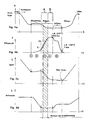
- FIG. 1 shows the basic principle of the new solution.
- the quadrangle V DE top left represents the volume of the cavities at the end of the injection phase.
- the arrow Pr shows the direction of the embossing movement, the dot-dash line V DP meaning the reduced volume at the end of the embossing phase.
- the hatched part V PM symbolizes the injected embossing mass, which is smaller than the volume of the cavity V DE .
- the arrow E means the injection direction and the double arrow D K the two flow directions for a correction of the injected mass.
- M P is the mass cushion at the end of the injection process, which is kept constant by the return flow lock.
- the liquid mass is injected by the linear movement of the injection screw via the injection nozzle channel E DK via the sprue AK into the cavity.
- a certain pressure D B1 is established , which is detected via a pressure sensor Sp and fed to the control for the embossing movement as a pressure actual value.
- FIG. 2 shows somewhat more concretely the situation at the end of the injection phase. At least theoretically, it is possible the illustrated pressure correction already at the end to carry out the injection phase or dosing phase Dos.
- the illustrated pressure correction already at the end to carry out the injection phase or dosing phase Dos.
- the time is seen, immediately after the melt by the embossing movement, the cavities (Kav) completely have completed. It is the time with a very strong pressure change through the Increasing embossing force on the complete, caged casting mass (Ma).
- FIG. 3 a shows a further advantageous embodiment of the invention Improvement of control accuracy.
- the mechanical game of all correspondingly effective mechanically movable parts by a biasing spring 50 canceled. It is important that the biasing spring acts in the same direction like the strength building for the embossing.
- FIG. 3b shows a section through a Bearing 51 of a column axis 56. On the two outer sides is ever one Seal 52 and 53 attached. This allows, inside the storage a Include grease lubrication, so that here too the requirement of a long Lifespan as well as the cleanroom use are ensured.
- the optimal control target is within about 180 °, as can be seen in FIG. 3c.
- Three different positions are shown in FIG. 3c.
- the shape is open;
- Rotation angle ⁇ 2 represents the embossing gap and
- ⁇ 3 represents the position at the maximum embossing force.
- the crank can be in the dead center position or close to the dead center.
- F means the effective force on the deformable parts of the machine, in particular on the columns 30.
- the tool mounting plate 16 is symbolically mounted on rollers 54 and the tool mounting plate on rollers 55 ( Figure 5a). This is to make it clear that both tool platens 11 and 16 are displaceable perpendicular relative to the drive carrier plate 15 and thus relatively movable.
- Figures 4a and 4b show qualitatively the course of the most important parameters, the position of the mold and the embossing force.
- Figures 4c and 4d show the gap and the screw path over the same time scale.
- Designation SK closure force
- Fp Averaging for the elimination of random fluctuations: Fp50.
- FIG. 5a shows, according to FIG. 6b, a basic diagram with the mechanical engineering core elements.
- K f is the spring constant of the column 30, optionally including the other deformable components, as far as the resulting deformation under a corresponding load, the distance S between the platens 11 and 16 influenced.
- the drive support bar 15 is designated PLfix. In this construction concept, the drive carrier plate is rigid or fixed on the machine stand. When crank mechanism 18 is indicated by ⁇ the rotation angle.
- FIG. 5b is the solid line 45 of the theoretical force curve on End of the closing movement shown.
- the thick line 44 shows the effective Force curve on both halves of the mold due to the hook's characteristics of Deformation of the columns as well as the plates, with a CD-clamping unit with 50mm Opening stroke.
- the lower line 46 shows the velocity profile and the curve 47 the course of the eccentric movement for a CD-form fit.
- FIG. 6a With the known solution according to FIG. 6a, the prior art discloses a CD in FIGS Seconds or less. It is a solution of the applicant. It is a fully hydraulic machine 10 with very good properties in terms of The machine stability and has three pillars, as well as the possibility for a short and as a long-stroke. The short stroke is 70 to 80 mm, and the closing force is at about 600 kN. The maintenance stroke is about a total of 300 mm.
- a form plate 1 is firmly connected to a machine stand 8.
- the tie rods 2 are screwed to the mold plate 1, wherein at the other end of the tie rods 2 a Piston head 3 is located within a cylinder 4.
- the mold plate 5 is in one Production position drawn, the piston head 3 constantly against a shoulder the tie rods 2 presses. With relatively small forces moves over two Auxiliary cylinder a closing piston forward and backward over the entire short stroke. Only for the application of the great closing force is the corresponding oil pressure in one Piston chamber applied.
- the machine 10 is open with the protective door 6, with a view the positive connection and the injection cylinder 7, shown.
- the raw material is over Filling container 9 fed to the machine, heated by the injection cylinder and under Pressure injected into the cavities of the molds.
- Figure 6b shows pictorially the basic concept for the production of flat Data carriers, such as compact discs, the transition from the injection phase in the Embossing phase.
- a cavity Kav which ultimately the outer shape of the Data carrier determined.
- Unchanged validity has the fact that for the highest demands a lot of the spray mass dosed into the cavity is pressed, but only so much that the cavity is only partially filled.
- Prior to the filling is done by moving the mold plate 1 or the mold plate. 5 formed a predetermined compression gap.
- the amount of spray mass is Ma designated.
- FIG. 8c shows a per se known one Building concept for the form movement.
- the default setting of the compression gap becomes achieved by moving the mold plate 1 by an electric motor. After completion of the Dosage is generated via oil pressure the force required for embossing. there It is a hybrid solution with all the advantages and disadvantages of the two Drive means.
- Figure 6b shows an example of the new solution.
- the Langhubarmeplatte 11 can, depending on the chosen concept, fixed or movably arranged on the machine stand 8.
- a compact unit 14 with a crank drive On the right Image page is as a preferred solution, a compact unit 14 with a crank drive.
- the assembly 14 consists of a drive carrier plate 15 and a movable platen 16 on a guide 20 on the Machine bed 8 rests, and a crank support structure 17.
- a crank mechanism 18th is on the one hand via a pin 19 in the movable platen 16th and on the other hand via an eccentric 21 in the crank support structure 17 articulated stored, such that the crank 22, according to the eccentricity e, the Crank movement can perform.
- the eccentricity e corresponds to half the lifting height (H / 2).
- On the opposite side of the movable platen 16 is the one mold half 23. With the two mold halves 12 and 23rd arises in the closed state, the cavity 24 for the deposit of the desired disc-shaped molding. Usually, the CD is not directly in the cavity 24 poured. In the cavity is one or both sides each stamper 25, 26th inserted, which as a negative mold, the cavity for the flat to be produced Have disk.
- Each column 30 is anchored on the nozzle-side platen 11 via a nut 31.
- a rotatable collar 32 attached, which via a ring gear 33 engages in a toothed tire 34.
- the fixed nut 31 engages over an internal thread on the threaded hole 35 of each column.
- a rotational movement of the Sprocket or timing belt is by the rotation of the columns on the nut 31 and the threaded portion 35 of the columns in a linear movement (arrows 36) of nozzle-side platen 11 implemented. This movement represents the Long or maintenance stroke is and is primarily needed for Stamperschnellic.
- FIG. 8c schematically shows the or overdrive for the column nuts or the long stroke with an electric motor 40 with drive pinion 41 and the drive for the short stroke via an electric motor 42, a gear 43 and the eccentric 21.
- the injection unit with plasticizing are the nozzle-side tool clamping plate 11 and both electric motor drives the other, fixed support plate assigned.
- the maintenance hub will be with you known "mold height adjustment" by means of rim and gears to the Driven column nuts.
- the rotation of the columns with a Timing belt can be realized.
Landscapes
- Engineering & Computer Science (AREA)
- Manufacturing & Machinery (AREA)
- Mechanical Engineering (AREA)
- Injection Moulding Of Plastics Or The Like (AREA)
- Moulds For Moulding Plastics Or The Like (AREA)
Abstract
Die Erfindung betrifft eine Spritzgiessmaschine für die Herstellung von Präzisionsteilen, insbesondere von flachen optischen Datenträgern, mit einer Spritzgiessmaschine mit zwei Formhälften, einer angetriebenen Formhälfte sowie einer Gegenformhälfte sowie einem Prägeanrieb, wobei der Kraftschluss zwischen der angetriebenen Formhälfte und der Gegenformhälfte bei der Grundeinstellung und dem ganzen Spritzzyklus über antreibbare Säulen der Spritzgiessmaschine herstellbar ist, welche sich in Funktion des Prägekraftverlaufes dehnen und das Spaltmass zwischen der angetriebenen Formhälfte und der Gegenformhälfte entsprechend beeinflussen. <IMAGE>The invention relates to an injection molding machine for the production of precision parts, in particular flat optical data carriers, with an injection molding machine with two mold halves, a driven mold half and a Gegenformhälfte and a embossing drive, wherein the frictional connection between the driven mold half and the Gegenformhälfte in the default setting and the whole Injection cycle on drivable columns of the injection molding machine can be produced, which stretch as a function of the embossing force curve and influence the gap between the driven mold half and the Gegenformhälfte accordingly. <IMAGE>
Description
Die Erfindung betrifft eine Spritzgiessmaschine für die Herstellung von Präzisionsteilen, insbesondere von flachen optischen Datenträgern, mit einer Spritzgiessmaschine mit zwei Formhälften, einer angetriebenen Formhälfte sowie einer Gegenformhälfte sowie einem Prägeantrieb, wobei der Kraftschluss zwischen der angetriebenen Formhälfte und der Gegenformhälfte bei der Grundeinstellung und dem ganzen Spritzzyklus über antreibbare Säulen der Spritzgiessmaschine herstellbar ist, welche sich in Funktion des Prägekraftverlaufes dehnen und das Spaltmass zwischen der angetriebenen Formhälfte und der Gegenformhälfte entsprechend beeinflussen.The invention relates to an injection molding machine for the production of precision parts, in particular of flat optical data carriers, with an injection molding machine with two mold halves, a driven mold half and a Gegenformhälfte and a stamping drive, wherein the adhesion between the driven mold half and the mold half in the basic setting and the entire injection cycle can be produced via drivable columns of the injection molding machine, which stretch as a function of the embossing force curve and the gap between the driven mold half and the counter-mold half influence accordingly.
Die Gattung der Spritzgiessmaschinen für die Herstellung von flachen Datenträgern
weist grundsätzlich zwei Formhälften auf. Die eine bewegliche, erste Formhälfte wird
mittels Antriebssystem gegenüber einer Antriebsträgerplatte für das Formschliessen
sowie das Formöffnen bewegt. Die Formbewegung kann z.B. auf Grund einer Weg-,
einer Druck- und/oder einer Geschwindigkeitsfunktion gesteuert werden. Die GB-PS
1 226 118 schlägt vor, den Geschwindigkeitsablauf der Formbewegung für bestimmte
Abschnitte eines Giesszyklusses nach vorgegebenen Programmen zu steuern. Bei
der Verwendung von Hydraulikzylindern als Antriebssystem lässt sich die Geschwindigkeit
der beweglichen Formhälfte über die Oelmenge steuern und/oder regeln. Mit
einem zusätzlichen Oeltemperaturparameter kann so mit hoher Genauigkeit ein
optimaler Geschwindigkeitsverlauf der bewegbaren Formhälfte sichergestellt werden.The type of injection molding machines for the production of flat data carriers
basically has two mold halves. The one moving, first half of the mold is
by means of drive system with respect to a drive carrier plate for the mold closing
as well as the mold opening moves. The molding movement may be e.g. due to a way,
a pressure and / or a speed function are controlled. The GB-
Die Praxis zeigt, dass selbst wenn alle Möglichkeiten der Steuer- und Regeltechnik im Hinblick auf die baulichen Elemente, wie dargestellt wurde, ausgeschöpft sind, die Endprodukte, vor allem in Bezug auf das Gewicht jeder einzelnen Platte, unverhältnismässig grosse Variationen aufweisen können. Testwägungen haben gezeigt, dass innerhalb einer Seriefabrikation im Extremfalle Gewichtsunterschiede bis zu 10% zwischen der leichtesten und der schwersten CD durchaus festgestellt werden können. Vom Erfinder ist erkannt worden, dass die äusseren Parameter wie
- exaktes Voreinstellen des Kompressionsspaltes
- exakte Bedingungen für den Übergang von der Spritz- in die Prägephase
- sowie abschnittsweises, exaktes Geschwindigkeitsführen der Prägephase
- exact presetting of the compression gap
- exact conditions for the transition from the injection to the embossing phase
- as well as section-wise, exact velocity guidance of the embossing phase
Beim klassischen Spritzgiessen wird höchste Genauigkeit, auch im Hinblick auf die Konstanz der Gewichtsgenauigkeit der Endprodukte, erreicht. Dies ist vor allem auf die Tatsache zurückzuführen, dass nach dem Einspritzen eine relativ lange Nachdruckphase gängige Praxis ist. Während der Nachdruckphase, welche über die Bewegung der Einspritzschnecke kontrolliert wird, werden kleinste Mengenvariationen der zuvor eingespritzen flüssigen Kunststoffmasse korrigiert. Bei der Herstellung von flachen optischen Datenträgern kennt man die sogenannte Nachdruckphase nicht. An die Stelle der Nachdruckphase ist ein vollflächiges Zusammendrücken der Giessform Voraussetzung, damit überhaupt die Oberflächenstruktur mit den eingeprägten Daten in der extrem hohen Qualität erreichbar ist. Durch die Platzverhältnisse und die extrem kurzen Zykluszeiten bedingt ist ein aktives bzw. gesteuertes Schliessen der Einspritzdüse unrealistisch.In classical injection molding, the highest accuracy, also with regard to the Constancy of weight accuracy of the final products achieved. This is mostly up attributed the fact that after injecting a relatively long Repressive phase is common practice. During the pressure phase, which over the Movement of the injection screw is controlled, are smallest quantity variations corrected the previously injected liquid plastic mass. In the Production of flat optical data carriers is known as the so-called Repressing phase not. In place of the emphasis phase is a full-surface Compression of the mold condition, so that at all the surface structure achievable with the impressed data in the extremely high quality. Due to the space available and the extremely short cycle times conditioned is an active or controlled closing of the injector unrealistic.
Der Erfindung wurde nun die Aufgabe gestellt, eine Vorrichtung zu entwickeln, welche höhere Verstellgeschwindigkeiten und kürzere Umrüstzeiten und eine höchste Qualität des Endproduktes und vor allem auch eine hohe Gewichtsgenauigkeit der flachen Datenträger sicherstellen können.The object of the invention was therefore to develop a device which higher adjustment speeds and shorter changeover times and a highest Quality of the end product and above all a high weight accuracy of the ensure flat media.
Die erfindungsgemässe Spritzgiessmaschine ist dadurch gekennzeichnet, dass der
Säulenantrieb den Säulen zugeordnete Vorspannfedern aufweist. Für besonders
vorteilhafte Ausgestaltungen des Verfahrens wird auf die Ansprüche 2 bis 5 Bezug
genommen.The inventive injection molding machine is characterized in that the
Column drive has associated with the columns biasing springs. For special
advantageous embodiments of the method is based on the
Die neue Lösung geht von zwei grundlegenden maschinenbaulichen Sachverhalten
aus:
Vom Erfinder ist erkannt worden, dass als eigentlich kritische "äussere Grössen" im Falle eines elektromechanischen Antriebes die beiden Parameter:
- Wegfunktion und
- wirksame Kompression
- Path function and
- effective compression
Als zur Zeit beste Erfindung kann die neue Lösung bei der Gattung von Spritzgiessmaschinen angewendet werden, wie sie in der WO00/47389 der Anmelderin beschrieben ist. Es handelt sich um eine Maschine mit einem sogenannten Lang- und einem Kurzhub. Beide Bewegungen werden über einen elektromotorischen Antrieb sichergestellt. Das Konzept sieht vor, dass die Antriebsträgerplatte ortsfest mit dem Ständer verbunden ist, wohingegen die beiden Formhälften relativ zueinander und zum Maschinenständer verschiebbar gelagert sind. Die Kompressionsfunktion (K x F) wird zumindest primär aufgrund der Säulendehnung (K) sowie der wirksamen Kompressionskraft (F) ermittelt. Mit der Säulendehnung bzw. dem Faktor K können alle übrigen Verformungsfaktoren, z.B. der verschiedenen Platten, miterfasst werden. Die Kompressionskraft kann auf verschiedenste Weise ermittelt und z.B. in erster Näherung aus dem Drehmoment des Antriebsmotores abgeleitet werden. Nachteilig ist dabei, dass Reibfaktoren, genau so wie Beschleunigungskräfte das Ergebnis verfälschen. Bevorzugt werden geeignete Drucksensoren aus dem Bereich der Formen oder aber Sensoren für die Dehnung der Säulen zur Ermittlung der wirksamen Kompression zugrunde gelegt. Im Falle der Messung der Säulendehnung reduziert sich die Steuerung/Regelung beim Fehlen einer Kompression vor allem auf die Wegfunktion, da in diesem Fall die wirksame Kompression gleich Null ist. Besonders bevorzugt erfolgt der elektromotorische Antrieb über einen Servomotor und der mechanische Übertrieb über eine Kurbel oder einen Exzenter. Dabei kann die Wegfunktion aus der Stellung der Kurbel- oder des Exzenters (ϕ) abgeleitet und entsprechend der Positionserkennung aus der Regelung des Servomotores ermittelt werden. Die realen Verhältnisse in den Kavitäten der Formen lassen sich aus der Wegfunktion der angetriebenen Platte [f(ϕ)] sowie der Kompressionsfunktion (K x F) mit höchster Genauigkeit ermitteln, so dass die Antriebsmittel über mehrere Prägeteilschritte nach einem vorgegebenen Geschwindigkeitsprogramm optimal gesteuert werden können. Der Kurbel- bzw. Exzenterantrieb hat nicht nur den enormen Vorteil, dass in Totpunktnähe eine maximale Anpresskraft erzeugt werden kann, sondern auch, dass die Bewegungsfunktion aus der Umsetzung einer Kreisbewegung in eine Linearbewegung geometrisch mit höchster Genauigkeit definierbar und aus der Positionsstellung im Servomotor herleitbar ist. Sinngemäss kann jedoch auch ein Kniehebel oder eine Zahnstange sowie eine Kombination beider sehr vorteilhaft eingesetzt werden.As at present best invention, the new solution in the genus of Injection molding machines are used, as described in WO00 / 47389 of Applicant is described. It is a machine with one so-called long and one short stroke. Both movements will be over one electromotive drive ensured. The concept provides that the Drive carrier plate is fixedly connected to the stand, whereas the two Mold halves are mounted relative to each other and the machine frame displaced. The compression function (K x F) is at least primarily due to column elongation (K) and the effective compression force (F) determined. With the column stretch or the factor K, all other deformation factors, e.g. the different ones Plates to be recorded. The compression force can be in many different ways determined and e.g. in a first approximation from the torque of the drive motor be derived. The disadvantage here is that friction factors, just like Acceleration forces distort the result. Preferred are suitable Pressure sensors from the field of forms or sensors for the expansion of the Pillars used to determine the effective compression. In case of Measuring the column expansion reduces the control / regulation in the absence of a Compression mainly on the way function, since in this case the effective Compression is zero. Particularly preferred is the electromotive Drive via a servo motor and mechanical overdrive via a crank or an eccentric. The Wegfunktion from the position of the crank or the Exzenters (φ) derived and according to the position detection from the scheme be determined of the servo motor. The real conditions in the cavities of the Shapes can be calculated from the path function of the driven plate [f (φ)] and the Compression function (K x F) with highest accuracy determine, so that the Drive means over several embossing parts steps after a predetermined Speed program can be optimally controlled. The crank or Eccentric drive not only has the enormous advantage that close to dead center one maximum contact force can be generated, but also that the Motion function from the conversion of a circular motion into a linear motion geometrically definable with highest accuracy and from the position position in the Servomotor is derivable. Analogously, however, a toggle lever or a Rack and a combination of both are used very advantageous.
Gemäss der bevorzugten Lösung wird der Exzenter- oder Kurbelantrieb einerseits auf der fixen Antriebsträgerplatte abgestützt und ist anderseits mit der angetriebenen Platte verbunden. Der Exzenter- bzw. Kurbelantrieb wird derart ausgelegt, dass der Prägehub für die maximale Kompression in Totpunktnähe nutzbar ist, wobei bevorzugt bei maximaler Kompression ein Restspalt (S) zwischen den beiden Formhälften verbleibt. Der elektromechanische Antrieb weist einen Servomotor mit Positionserkennung für die angetriebene Platte auf, wobei bevorzugt wenigstens einzelne Prägeschritte über ein Geschwindigkeitsprogramm steuerbar sind.According to the preferred solution of the eccentric or crank drive on the one hand the fixed drive carrier plate is supported and on the other hand with the driven Plate connected. The eccentric or crank drive is designed such that the Punching stroke for maximum compression near the dead center is usable, wherein preferably at maximum compression, a residual gap (S) between the two Mold halves remains. The electromechanical drive has a servomotor Position detection for the driven plate, wherein preferably at least Individual embossing steps are controllable via a speed program.
Auf der maschinenbaulichen Seite wurde bisher als optimale Lösung befunden, wenn die beiden Formhälften zwischen einer angetriebenen Platte und einer Gegenplatte über Säulen gehalten, mittels eines elektromechanischen Antriebes verspannt werden und die Antriebsmittel auf der Basis der Wegfunktion der angetriebenen Platte und der wirksamen Kompression bzw. der Maschinendehnung im Sinne eines Basisprogrammes programmsteuerbar sind. Bei diesem Vorschlag werden zwei völlig unterschiedliche Parameter zu einer echten Synthese verbunden. Neben der direkt durch den Antrieb verursachten Bewegung und die durch die Kompression verursachte Maschinenverlängerung als äussere Parameter werden die inneren Parameter, insbesondere die Gewichtsmenge der eingespritzten Masse, durch eine Detektion des Druckes kontrolliert und soweit erforderlich korrigiert. Die Kompressionsfunktion (K x F) wird auf Grund der Maschinendehnung (K) sowie der wirksamen Kompressionskraft (F) ermittelt. Vorteilhafterweise erfolgt der elektromotorische Antrieb über einen Servomotor und der mechanische Übertrieb über eine Kurbel, einen Exzenter, Kniehebel oder über Zahnstangen. Wenn der mechanische Übertrieb über eine Kurbel oder einen Exzenter erfolgt und die Wegfunktion aus der Kurbel- oder Exzenterstellung (ϕ) abgeleitet wird, kann die Positionserkennung aus der Regelung des Servomotores ermittelt werden. Der totale Prägehub bzw. Kompressionsweg wird aus der Wegfunktion der angetriebenen Platte [f(ϕ)] sowie der Kompressionsfunktion (K x F) ermittelt und die Antriebsmittel, zumindest während mehreren Prägeteilschritten, nach einem Geschwindigkeitsprogramm gesteuert.On the engineering side has been found to be the optimal solution, if the two mold halves between a driven plate and a counter-plate held by columns, are clamped by means of an electromechanical drive and the drive means based on the travel function of the driven plate and the effective compression or machine expansion in the sense of a basic program are programmable. In this proposal, two are completely different parameters connected to a real synthesis. In addition to the direct caused by the drive movement and that caused by the compression Machine extension as external parameters become the internal parameters, in particular the amount by weight of the injected mass, by a detection of the Controlled pressure and corrected as necessary. The compression function (K x F) is due to the machine elongation (K) and the effective compression force (F) determined. Advantageously, the electric motor drive via a Servomotor and mechanical overdrive via a crank, an eccentric, Toggle or over racks. When the mechanical overdrive over a crank or an eccentric takes place and the path function from the crank or Eccentric position (φ) is derived, the position detection from the control be determined of the servo motor. The total impression stroke or compression path is derived from the path function of the driven plate [f (φ)] and the compression function (K x F) and the drive means, at least during several Embossing steps, controlled according to a speed program.
In der Folge wird die Erfindung an Hand von einigen Beispielen mit weiteren Einzelheiten erläutert. Es zeigen:
- die
Figur 1 - ein Schema für das Grundprinzip der neuen Lösung;
- die
Figur 2 - eine vereinfachte Darstellung für das Spritzgiessen von flachen optischen Datenträgern;
- die Figur 3a
- die Spielaufhebung einer Lösung gemäss Figuren 6a - 6c;
- die Figur 3b
- die Lagerung einer Säule in grösserem Massstab;
- die Figur 3c
- die Exzenter- bzw. Kurbelbewegung;
- die Figuren 4a bis 4d
- verschiedene Diagramme, dargestellt über der Zeit, Figur 4a die Lage der Form, die Figur 4b die Prägekraft, die Figur 4c den Prägespalt und die Figur 4d die Position der Einspritzschnecke;
- die Figur 5a
- ein Beispiel für das maschinenbauliche Grundprinzip der neuen Lösung;
- die Figur 5b
- den theoretischen Kraftverlauf am Ende der Schliessbewegung beim Aufbau der Prägekraft;
- die Figur 5c
- die Funktion von Position und Drehwinkel für den Kurbeltrieb;
- die Figur 6a
- eine Spritzgiessmaschine des Standes der Technik für die Herstellung von z.B. CDs;
- die Figur 6b
- ein vorteilhaftes, maschinenbauliches Grundkonzept der Formschliesseinheit für die neue Lösung;
- die Figur 6c
- schematisch ein Schnitt einer Drei-Säulenmaschine.
- the figure 1
- a scheme for the basic principle of the new solution;
- the figure 2
- a simplified representation for the injection molding of flat optical data carriers;
- the figure 3a
- the clearance of a solution according to Figures 6a - 6c;
- Figure 3b
- the storage of a column on a larger scale;
- Figure 3c
- the eccentric or crank movement;
- Figures 4a to 4d
- 4b shows the position of the mold, FIG. 4b shows the embossing force, FIG. 4c shows the embossing gap, and FIG. 4d shows the position of the injection screw.
- the figure 5a
- an example of the basic mechanical engineering principle of the new solution;
- Figure 5b
- the theoretical force curve at the end of the closing movement when building up the embossing force;
- the figure 5c
- the function of position and angle of rotation for the crank mechanism;
- Figure 6a
- an injection molding machine of the prior art for the production of eg CDs;
- Figure 6b
- an advantageous, basic mechanical engineering concept of the mold closing unit for the new solution;
- the figure 6c
- schematically a section of a three-post machine.
Die Figur 1 zeigt das Grundprinzip der neuen Lösung. Das Viereck VDE links oben stellt das Volumen der Kavitäten am Ende der Einspritzphase dar. Der Pfeil Pr zeigt die Richtung der Prägebewegung, wobei die strichpunktierte Linie VDP das verkleinerte Volumen am Ende der Prägephase bedeutet. Der schraffierte Teil VPM symbolisiert die eingespritzte Prägemasse, welche kleiner ist als das Volumen der Kavität VDE. Der Pfeil E bedeutet die Einspritzrichtung und der Doppelpfeil DK die beiden Strömungsrichtungen für eine Korrektur der eingesprpitzten Masse. MP ist das Massepolster am Ende des Einspritzvorganges, welches durch die Rückstromsperre konstant gehalten wird. Beim Einspritzen wird die flüssige Masse durch die Linearbewegung der Einspritzschnecke über den Einspritzdüsenkanal EDK über den Angusskanal AK in die Kavität eingespritzt. Am Ende des Einspritzvorganges stellt sich ein bestimmter Druck DB1 ein, der über einen Drucksensor Sp detektiert und der Regelung für die Prägebewegung als Druck-Istwert zugeführt wird.FIG. 1 shows the basic principle of the new solution. The quadrangle V DE top left represents the volume of the cavities at the end of the injection phase. The arrow Pr shows the direction of the embossing movement, the dot-dash line V DP meaning the reduced volume at the end of the embossing phase. The hatched part V PM symbolizes the injected embossing mass, which is smaller than the volume of the cavity V DE . The arrow E means the injection direction and the double arrow D K the two flow directions for a correction of the injected mass. M P is the mass cushion at the end of the injection process, which is kept constant by the return flow lock. During injection, the liquid mass is injected by the linear movement of the injection screw via the injection nozzle channel E DK via the sprue AK into the cavity. At the end of the injection process, a certain pressure D B1 is established , which is detected via a pressure sensor Sp and fed to the control for the embossing movement as a pressure actual value.
Ist der Druck DB1 zum Messzeitpunkt grösser als der gewünschte Druck-Sollwert, wird mit dem geringstmöglichen Zeitverzug ein Korrektursignal auf die Prägebewegung VPr gegeben, wodurch sich eine zusätzliche Druckerhöhung DB1 x einstellt. Wird davon ausgegangen, dass zum Messzeitpunkt DB1 = DA1 (im Massepolster) ist, so stellt sich automatisch durch die korrigierte Prägebewegung (VPr) ein grösserer Druck BB1 x ein, welcher sofort eine Rückströmung von der Kavität in das Massepolster MP zur Folge hat. Als Alternative ist es möglich, eine sinngemässe Korrektur über die Bewegung bzw. Geschwindigkeit V der Einspritzschnecke, jeweils mit umgekehrter Bewegungsrichtung, vorzunehmen. Bei einem Zuviel an eingespritzter Masse in die Kavität wird der Druck DA1 abgesenkt, so dass dies gleicherweise zur beschriebenen Strömungsumkehr führt und eine Gewichtskorrektur für die fertige CD zur Folge hat. In der Praxis wird durch das Aufbringen der Prägekraft Pr R in den Formkavitäten eine Drucksteigerung DB1 x erzeugt, welche ein entsprechendes Rückströmen der Masse durch den Anguss verursacht. Die neue Erfindung beeinflusst mit der Druckänderung DB1, DB1 x die Rückströmgeschwindigkeit (DK) sehr gezielt. If the pressure D B1 at the time of measurement is greater than the desired pressure setpoint, a correction signal is applied to the embossing movement VPr with the least possible time delay, as a result of which an additional pressure increase D B1 x occurs. If it is assumed that at the time of measurement D B1 = D A1 (in the mass cushion), the corrected embossing movement (VPr) automatically sets a greater pressure B B1 x , which immediately causes a backflow from the cavity into the mass cushion M P Episode has. As an alternative, it is possible to make a correct correction via the movement or speed V of the injection screw, in each case with the reverse direction of movement. If there is too much injected mass in the cavity, the pressure D A1 is lowered, so that this likewise leads to the described flow reversal and results in a weight correction for the finished CD. In practice, by applying the embossing force Pr R in the mold cavities, a pressure increase DB 1 x generated, which causes a corresponding backflow of the mass through the sprue. The new invention has a very specific influence on the return flow velocity (DK) with the pressure change DB 1 , DB 1 x .
Die Figur 2 zeigt etwas konkreter die Situation am Ende der Einspritzphase. Zumindest theoretisch ist es möglich, die dargestellte Druckkorrektur bereits am Ende der Einspritzphase bzw. Dosierphase Dos vorzunehmen. Als idealer Zeitpunkt für die Detektion des Druckes in den Formen wird der Zeitpunkt gesehen, unmittelbar nachdem durch die Prägebewegung die Schmelze die Kavitäten (Kav) vollständig ausgefüllt haben. Es ist der Zeitpunkt mit einer sehr starken Druckänderung durch die zunehmende Prägekraft auf die vollständige, eingesperrte Giessmasse (Ma).FIG. 2 shows somewhat more concretely the situation at the end of the injection phase. At least theoretically, it is possible the illustrated pressure correction already at the end to carry out the injection phase or dosing phase Dos. As an ideal time for the Detection of the pressure in the forms, the time is seen, immediately after the melt by the embossing movement, the cavities (Kav) completely have completed. It is the time with a very strong pressure change through the Increasing embossing force on the complete, caged casting mass (Ma).
Die Figur 3a zeigt einen weiteren vorteilhaften Ausgestaltungsgedanken für die
Verbesserung der Regelgenauigkeit. Für dieses Ziel wird das mechanische Spiel aller
entsprechend wirksamen mechanisch bewegbaren Teile durch eine Vorspannfeder 50
aufgehoben. Wichtig dabei ist, dass die Vorspannfeder in die selbe Richtung wirkt
wie der Kraftaufbau für die Prägung. Die Figur 3b zeigt einen Schnitt durch eine
Lagerstelle 51 einer Säulenachse 56. An den beiden äusseren Seiten ist je eine
Dichtung 52 bzw. 53 angebracht. Dies gestattet, im Inneren der Lagerung eine
Fettschmierung einzuschliessen, so dass auch hier die Forderung einer langen
Lebensdauer sowie der Reinraumeinsatz sichergestellt sind.FIG. 3 a shows a further advantageous embodiment of the invention
Improvement of control accuracy. For this goal, the mechanical game of all
correspondingly effective mechanically movable parts by a biasing
Das optimale Regelziel liegt innerhalb von etwa 180°, wie aus der Figur 3c erkennbar
ist. In der Figur 3c sind drei unterschiedliche Lagen dargestellt: Beim Drehwinkel ϕ1
ist die Form offen; Drehwinkel ϕ2 stellt den Prägespalt und ϕ3 die Stellung bei der
maximalen Prägekraft dar. Bei der maximalen Prägekraft kann die Kurbel in der
Totpunktlage oder aber in Totpunktnähe sein. F bedeutet die wirksame Kraft auf die
deformierbaren Teile der Maschine, insbesondere auf die Säulen 30. Die
Werkzeugaufspannplatte 16 ist symbolisch auf Rollen 54 und die
Werkzeugaufspannplatte auf Rollen 55 gelagert (Figur 5a). Damit soll deutlich
gemacht werden, dass beide Werkzeugaufspannplatten 11 und 16 senkrecht in
Bezug auf die Antriebsträgerplatte 15 verschiebbar und damit relativ zueinander
bewegbar sind. Als Konsequenz aus den Relativbewegungen der beiden Formhälfen
12 und 23 ergibt sich eine direkte Änderung des Distanzmasses S, je nach örtlicher
Lage der beiden Werkzeugaufspannplatten 11 und 16. Sinngemäss ist die
Werkzeugaufspannplatte 11 mit Pl bezeichnet. Die Werkzeugaufspannplatte 11
bewegt sich mit der Funktion K · F und die Werkzeugaufspannplatte 16 mit der
Funktion X = f (ϕ). Für das Distanzmass S ergibt sich die folgende Funktion:
Die Figuren 4a und 4b zeigen qualitativ den Verlauf der wichtigsten Parameter die
Lage der Form sowie die Prägekraft. Die Figuren 4c und 4d zeigen den Spalt sowie
den Schneckenweg über dem selben Zeitmassstab. Für die Schliesskraftregelung
beim Prägen gelten die folgenden Zusammenhänge: Bestimmung SK (Schliesskraft)
am Prägeende: Fp. Mittelwertbildung zur Eliminierung von zufälligen Schwankungen:
Fp50. Regelfehler: ΔF = FSoll Prägen - Fp50 = Temp.einfluss. Regelziel: ϕ = 180°
In den Figuren 4a bis 4d ist zusätzlich der Grundgedanke für die Korrektur in einem
ersten Abschnitt A der Prägephase markiert. Der Punkt X stellt symbolisch eine erste,
realistisch mögliche Messung des Druckes bei Beginn der Prägephase dar, wobei XK
sinngemäss eine Ist-Druckkurve darstellt. Am Ende des ersten Abschnittes A muss
die Korrektur, eventuell eine wiederholte Korrektur, vollständig abgeschlossen sein,
so dass bei Beginn des zweiten Abschnittes B nach Einfrieren des Angusses mit der
exakt erforderlichen Masse die Prägephase durchgeführt werden kann. Am Ende der
Prägephase hat die Schmelze zu der Kavität noch eine Temperatur von z.B. 200°C,
dies bei etwa 800 bar. Am Ende der Kühlphase ist das Produkt bereits auf 120°C
abgekühlt, dies bei einem bar. Der ganze Giesszyklus kann auf die folgenden sechs
Punkte reduziert werden:
(Fliesswiderstand) Prägespalt positionsgeregelt (öffnet leicht über Säulendehnung)
A Kuchen verteilen: Nachdruck aufbauen → DFP weicht unter
Säulendehnung aus; → Anguss noch nicht eingefroren, Masseverlust durch Rückströmung im Schneckenvorderteil, mit Prägegeschwindigkeit wird Masseverlust gesteuert.
(Flow resistance) Precision gap position-controlled (opens slightly over column expansion)
A Spread cake: Build up pressure → DFP dodges
Column stretch out; → Sprue not yet frozen, loss of mass due to backflow in the screw front part, with stamping speed, loss of mass is controlled.
Die Figur 5a zeigt entsprechend Figur 6b ein Grundschema mit den maschinenbaulichen
Kernelementen. Dabei bedeutet Kf die Federkonstante der Säule 30,
gegebenenfalls mit Einschluss der übrigen deformierbaren Bauteile, soweit die
resultierende Deformation unter einer entsprechenden Belastung die Distanz S
zwischen den Werkzeugaufspannplatten 11 und 16 beeinflusst. Die Antriebsträgerlatte
15 ist mit PLfix bezeichnet. In diesem Baukonzept ist die Antriebsträgerplatte
starr bzw. fix auf dem Maschinenständer. Beim Kurbeltrieb 18 ist mit ϕ der
Drehwinkel angegeben.FIG. 5a shows, according to FIG. 6b, a basic diagram with the mechanical engineering core elements. In this case, K f is the spring constant of the
In der Figur 5b ist mit der ausgezogenen Linie 45 der theoretische Kraftverlauf am
Ende der Schliessbewegung dargestellt. Die dicke Linie 44 zeigt den effektiven
Kraftverlauf auf beide Formhälften auf Grund der hook'schen Kennlinien der
Verformung der Säulen sowie der Platten, bei einer CD-Schliesseinheit mit 50mm
Öffnungsweg. In Figur 5c zeigt die untere Linie 46 den Geschwindigkeitsverlauf und
die Kurve 47 den Verlauf der Exzenterbewegung für einen CD-Formschluss.In the figure 5b is the
Mit der bekannten Lösung gemäss Figur 6a wird im Stand der Technik eine CD in 3,7
Sekunden oder weniger hergestellt. Es handelt sich um eine Lösung der Anmelderin.
Es ist eine vollhydraulische Maschine 10 mit sehr guten Eigenschaften in Bezug auf
die Maschinenstabilität und weist drei Säulen sowie die Möglichkeit für einen Kurzsowie
einen Langhub auf. Der Kurzhub liegt bei 70 bis 80 mm, und die Schliesskraft
ist bei etwa 600 kN. Der Wartungshub liegt bei etwa total 300 mm. Eine Formplatte
1 ist fest mit einem Maschinenständer 8 verbunden. Die Zugstangen 2 sind
verschraubt mit der Formplatte 1, wobei am anderen Ende der Zugstangen 2 ein
Kolbenkopf 3 sich innerhalb eines Zylinders 4 befindet. Die Formplatte 5 ist in einer
Produktionsstellung gezeichnet, wobei der Kolbenkopf 3 dauernd gegen eine Schulter
der Zugstangen 2 drückt. Mit relativ geringen Kräften bewegt sich über zwei
Hilfszylinder ein Schliesskolben vor- und rückwärts über den ganzen Kurzhub. Nur für
das Aufbringen der grossen Schliesskraft wird der entsprechende Oeldruck in einer
Kolbenkammer aufgebracht. Für das Wechseln eines Stampers in der Form werden
die drei Zylinder an den Zugstangen angesteuert, und die Formplatte 5 öffnet sich um
den Wartungshub. Die Maschine 10 ist mit geöffneter Schutztüre 6, mit Sicht auf
den Formschluss und den Einspritzzylinder 7, dargestellt. Das Rohmaterial wird über
Füllbehälter 9 der Maschine zugeführt, über den Einspritzzylinder erwärmt und unter
Druck in die Kavitäten der Formen gespritzt.With the known solution according to FIG. 6a, the prior art discloses a CD in FIGS
Seconds or less. It is a solution of the applicant.
It is a fully
Die Figur 6b zeigt bildlich das Grundkonzept für die Herstellung von flachen
Datenträgern, wie etwa Kompaktdisks, beim Übergang von der Einspritzphase in die
Prägephase. Im Zentrum ist eine Kavität Kav, welche letztlich die äussere Form des
Datenträgers bestimmt. Im Laufe der Entwicklung des Produktionsprozesses wurden
verschiedene Konzepte verfolgt. Unveränderte Gültigkeit hat die Tatsache, dass für
die höchsten Anforderungen eine Menge der Spritzmasse dosiert in die Kavität
gepresst wird, jedoch nur soviel, dass die Kavität nur teilweise gefüllt wird.
Vorgängig der Füllung wird durch Bewegen der Formplatte 1 oder der Formplatte 5
ein vorbestimmter Kompressionsspalt gebildet. Die Menge der Spritzmasse ist mit Ma
bezeichnet. Nach Abschluss der Formfüllphase bzw. des Einspritzvorganges wird der
eigentliche Prägevorgang eingeleitet. Beim Beispiel gemäss Figur 8c wird dafür die
Formplatte 1 in Richtung der Kavität bewegt und unter Aufbringen einer maximalen
Kraft der Formhohlraum bzw. die Kavität verkleinert und die Masse verdichtet. In
älteren Verfahren wurde dafür der Kompressionsspalt bis auf 0 aufgehoben. In der
neuen Lösung ist erkannt worden, dass die Werkzeuge nicht auf Anschlag gefahren
werden dürfen, dass vielmehr ein Restspalt für eine exakte Endregelung, auch nach
Abschluss der Prägung, verbleiben soll. Die Figur 8c zeigt ein an sich bekanntes
Baukonzpet für die Formbewegung. Die Voreinstellung des Kompressionsspaltes wird
elektromotorisch durch Bewegen der Formplatte 1 erzielt. Nach Abschluss der
Dosierung wird über Oeldruck die für das Prägen erforderliche Kraft erzeugt. Dabei
handelt es sich um eine Hybridlösung mit allen Vorteilen und Nachteilen der zwei
Antriebsmittel.Figure 6b shows pictorially the basic concept for the production of flat
Data carriers, such as compact discs, the transition from the injection phase in the
Embossing phase. In the center is a cavity Kav, which ultimately the outer shape of the
Data carrier determined. In the course of development of the production process were
pursued different concepts. Unchanged validity has the fact that for
the highest demands a lot of the spray mass dosed into the cavity
is pressed, but only so much that the cavity is only partially filled.
Prior to the filling is done by moving the
Die Figur 6b zeigt ein Beispiel der neuen Lösung. Auf der linken Bildseite der Figur 6b
ist die düsenseitige Werkzeugaufspannplatte bzw. Langhubträgerplatte 11 mit einer
Formhälfte 12 dargestellt, auf die hin, gemäss Pfeilen 13, die Einspritzdüse 7 zu- und
wegbewegt wird. Die Langhubträgerplatte 11 kann, je nach gewähltem Konzept, fest
oder beweglich an dem Maschinenständer 8 angeordnet werden. Auf der rechten
Bildseite befindet sich als eine bevorzugte Lösung eine kompakte Baueinheit 14 mit
einem Kurbelantrieb. Die Baueinheit 14 besteht aus einer Antriebsträgerplatte 15 und
einer beweglichen Werkzeugaufspannplatte 16, die auf einer Führung 20 auf dem
Maschinenbett 8 aufliegt, sowie einer Kurbelträgerkonstruktion 17. Ein Kurbeltrieb 18
ist einerseits über einen Bolzen 19 in der beweglichen Werkzeugaufspannplatte 16
und andererseits über einen Exzenter 21 in der Kurbeltragkonstruktion 17 gelenkig
gelagert, derart, dass die Kurbel 22, entsprechend der Exzentrizität e, die
Kurbelbewegung ausführen kann. Die Exzentrizität e entspricht der halben Hubhöhe
(H/2). Auf der gegenüberliegenden Seite der beweglichen Werkzeugaufspannplatte
16 befindet sich die eine Formhälfte 23. Mit den beiden Formhälften 12 sowie 23
entsteht in geschlossenem Zustand der Hohlraum 24 für die Einlage des gewünschten
scheibenförmigen Formteiles. Üblicherweise wird die CD nicht direkt in den Hohlraum
24 gegossen. In den Hohlraum wird ein- oder beidseitig je ein Stamper 25, 26
eingelegt, welcher als Negativform die Kavität für den herzustellenden flachen
Datenträger aufweist. Die Verankerungs- und Haltekraft zwischen den beiden Platten
wird durch drei oder gegebenenfalls vier Säulen 30 sichergestellt. Jede Säule 30 ist
auf der düsenseitigen Werkzeugaufspannplatte 11 über eine Mutter 31 verankert. An
der Antriebsträgerplatte 15 ist ein drehbeweglicher Bund 32 befestigt, welcher über
einen Zahnkranz 33 in einen Zahnreifen 34 eingreift. Die feste Mutter 31 greift über
ein Innengewinde auf den Gewindelauf 35 jeder Säule ein. Eine Drehbewegung des
Zahnkranzes oder des Zahnriemens wird durch die Drehung der Säulen auf die Mutter
31 und den Gewindelauf 35 der Säulen in eine Linearbewegung (Pfeile 36) der
düsenseitigen Werkzeugaufspannplatte 11 umgesetzt. Diese Bewegung stellt den
Lang- oder Wartungshub dar und wird primär beim Stamperschnellwechsel benötigt.
Der kurze Arbeitshub wird dagegen über den Kurbeltrieb 18 sowie die bewegliche
Werkzeugaufspannplatte 16 durchgeführt. Die Figur 8c zeigt schematisch den An-
bzw. Übertrieb für die Säulenmuttern bzw. den Langhub mit einem Elektromotor 40
mit Antriebsritzel 41 sowie den Antrieb für den Kurzhub über einen Elektromotor 42,
ein Getriebe 43 und den Exzenter 21. Die Einspritzeinheit mit Plastifizierzylinder sind
der düsenseitigen Werkzeugaufspannplatte 11 und beide elektromotorischen Antriebe
der anderen, festen Trägerplatte zugeordnet. Der Wartungshub wird mit einer an sich
bekannten "Formbauhöhenverstellung" mittels Radkranz und Zahnrädern an den
Säulenmuttern gefahren. Als Alternative kann die Drehung der Säulen mit einem
Zahnriemen realisiert werden. Mit der Lagerung der Säulen mit Wälzlagern in den
Formplatten und mit der Schmierung der Lager und der Verstellgewinde lassen sich
höhere Verstellgeschwindigkeiten und damit Umrüstungszeiten beim Wechsel der
Matrize (Stamper) von kleiner als 30 Sekunden erreichen. Neu wird deshalb auch für
diesen Antrieb ein Motor mit genau positionierbarer Achse, vorzugsweise ein
Servomotor mit spielarmem Getriebe, eingesetzt. Zwischen Kurbeltrieb und
elektrischem Antriebsmotor befindet sich ein Getriebe, vorzugsweise ein
Stirnradgetriebe. Mit C ist eine Steuer-/Regelintelligenz mit Speicher angedeutet,
welche der entsprechenden Motorsteuerung/Regelung die jeweils erforderlichen
Programmabläufe bzw. Rezepte vorgibt. Im Kasten C ist mit R1, R2, R3, usw.
angedeutet, dass beliebige Rechenleistungen direkt vor Ort installiert und
entsprechende Koordinationen direkt durchgeführt werden können. Sinngemäss
können die Steuerverbindungen St1, St2, St3 vorgesehen und eine entsprechende
Optimierung aller Steuer- und Regelabläufe sichergestellt werden.Figure 6b shows an example of the new solution. On the left side of Figure 6b
is the nozzle-side tool clamping plate or
Claims (5)
dadurch gekennzeichnet, dass der Säulenantrieb den Säulen zugeordnete Vorspannfedern aufweist.Injection molding machine for the production of precision parts, in particular flat optical data carriers with an injection molding machine with two mold halves, a driven mold half and a Gegenformhälfte and a embossing drive, wherein the adhesion between the driven mold half and the Gegenformhälfte in the basic setting and the entire injection cycle on drivable columns of Injection molding machine can be produced, which stretch as a function of the embossing force curve and influence the gap between the driven mold half and the counter-mold half accordingly
characterized in that the column drive comprises the columns associated biasing springs.
dadurch gekennzeichnet, dass zur Verbesserung der Regelgenauigkeit das Spiel aller entsprechend wirksamen mechanisch bewegbaren Teile aufhebbar ist.Injection molding machine according to claim 1,
characterized in that the game of all correspondingly effective mechanically movable parts can be canceled to improve the control accuracy.
dadurch gekennzeichnet, dass die Vorspannfedern in dem Bereich einer Lagerstelle mit Verstellgewinde angeordnet sind.Injection molding machine according to claim 1 or 2,
characterized in that the biasing springs are arranged in the region of a bearing with Verstellgewinde.
dadurch gekennzeichnet, dass die Lagerstelle beidseits abgedichtet ist und eine Fettschmierung der Lager und der Verstellgewinde aufweist.Injection molding machine according to claim 3,
characterized in that the bearing is sealed on both sides and has a grease lubrication of the bearing and the adjusting thread.
dadurch gekennzeichnet, dass der Antrieb zur Verstellung der Formeinbauhöhe einen Motor mit genau positionierbarer Achse vorzugsweise einen Servomotor mit spielramem Getriebe aufweist.Injection molding machine according to one of claims 1 to 4,
characterized in that the drive for adjusting the mold mounting height has a motor with a precisely positionable axis preferably a servo motor with spielramem transmission.
Applications Claiming Priority (3)
| Application Number | Priority Date | Filing Date | Title |
|---|---|---|---|
| CH25332000 | 2000-12-22 | ||
| CH25332000 | 2000-12-22 | ||
| EP01271939A EP1343621B1 (en) | 2000-12-22 | 2001-12-17 | Method and device for injection moulding flat optical data supports which have a precise weight |
Related Parent Applications (1)
| Application Number | Title | Priority Date | Filing Date |
|---|---|---|---|
| EP01271939A Division EP1343621B1 (en) | 2000-12-22 | 2001-12-17 | Method and device for injection moulding flat optical data supports which have a precise weight |
Publications (1)
| Publication Number | Publication Date |
|---|---|
| EP1568461A1 true EP1568461A1 (en) | 2005-08-31 |
Family
ID=4569921
Family Applications (2)
| Application Number | Title | Priority Date | Filing Date |
|---|---|---|---|
| EP01271939A Expired - Lifetime EP1343621B1 (en) | 2000-12-22 | 2001-12-17 | Method and device for injection moulding flat optical data supports which have a precise weight |
| EP05006085A Withdrawn EP1568461A1 (en) | 2000-12-22 | 2001-12-17 | Injection moulding machine for making precision parts |
Family Applications Before (1)
| Application Number | Title | Priority Date | Filing Date |
|---|---|---|---|
| EP01271939A Expired - Lifetime EP1343621B1 (en) | 2000-12-22 | 2001-12-17 | Method and device for injection moulding flat optical data supports which have a precise weight |
Country Status (5)
| Country | Link |
|---|---|
| EP (2) | EP1343621B1 (en) |
| CN (2) | CN1676306A (en) |
| AT (1) | ATE302679T1 (en) |
| DE (1) | DE50107228D1 (en) |
| WO (1) | WO2002051615A1 (en) |
Cited By (1)
| Publication number | Priority date | Publication date | Assignee | Title |
|---|---|---|---|---|
| WO2023057336A1 (en) * | 2021-10-06 | 2023-04-13 | Bayer Aktiengesellschaft | Thermally conductive microplates |
Families Citing this family (9)
| Publication number | Priority date | Publication date | Assignee | Title |
|---|---|---|---|---|
| TWI232162B (en) * | 2003-04-04 | 2005-05-11 | Sumitomo Heavy Industries | Injection-molding machine and method of controlling injection-molding machine |
| CN1795084A (en) * | 2003-05-22 | 2006-06-28 | 住友重机械工业株式会社 | Molding method, mold for molding, molded product, and molding machine |
| DE102004051292B3 (en) * | 2004-10-20 | 2006-08-03 | Karl Hehl | Method for injection molding of molded parts with an embossing process |
| DE102006008184A1 (en) * | 2006-02-22 | 2007-08-23 | Demag Ergotech Gmbh | Producing thin-walled plastics shaped article, with no restrictions on geometry, by combination of injection molding and stamping, with injection of plastics during closing of stamping mold |
| NL1032248C2 (en) * | 2006-07-28 | 2008-01-29 | Ecim Technologies Bv | Method and device for manufacturing products. |
| CA2755908C (en) | 2009-04-24 | 2013-05-28 | Husky Injection Molding Systems Ltd. | A cavity insert for a molding system, the cavity insert having a deformable portion |
| EP2826615B1 (en) | 2009-11-03 | 2019-05-29 | Husky Injection Molding Systems Ltd. | System for operating an injection molding machine |
| AT13974U1 (en) | 2013-07-30 | 2015-02-15 | Engel Austria Gmbh | Shaping machine with negative mold protection |
| DE102015117237B3 (en) | 2015-10-09 | 2017-03-23 | Kraussmaffei Technologies Gmbh | Method for determining a real volume of an injection-moldable mass in an injection molding process |
Citations (3)
| Publication number | Priority date | Publication date | Assignee | Title |
|---|---|---|---|---|
| US2790204A (en) * | 1955-05-24 | 1957-04-30 | Eastman Kodak Co | Injection molding machine with stress control system |
| JPH05293862A (en) * | 1992-04-21 | 1993-11-09 | Mitsubishi Electric Corp | Mold clamping force detection method and mold clamping force detection device for molding apparatus |
| US5338171A (en) * | 1991-04-17 | 1994-08-16 | Kabushiki Kaisha Komatsu Seisakusho | Die-clamping apparatus with aligning device |
Family Cites Families (6)
| Publication number | Priority date | Publication date | Assignee | Title |
|---|---|---|---|---|
| US4439132A (en) * | 1981-06-10 | 1984-03-27 | Discovision Associates | Hot sprue assembly for an injection molding machine |
| JPS615913A (en) * | 1984-06-20 | 1986-01-11 | Sumitomo Bakelite Co Ltd | Mold assembly of discoid recording medium base |
| JP2607961B2 (en) * | 1989-11-29 | 1997-05-07 | 日精樹脂工業 株式会社 | Injection molding method |
| JP3228026B2 (en) * | 1994-10-28 | 2001-11-12 | 松下電器産業株式会社 | Apparatus and method for manufacturing optical disc substrate |
| DE69826329T2 (en) * | 1997-07-07 | 2005-10-27 | Toyo Machinery & Metal Co. Ltd. | Injection molding with electrical actuation |
| JPH11120628A (en) * | 1997-10-08 | 1999-04-30 | Meiki Co Ltd | Method for molding disk molded goods |
-
2001
- 2001-12-17 EP EP01271939A patent/EP1343621B1/en not_active Expired - Lifetime
- 2001-12-17 EP EP05006085A patent/EP1568461A1/en not_active Withdrawn
- 2001-12-17 DE DE50107228T patent/DE50107228D1/en not_active Expired - Lifetime
- 2001-12-17 CN CN200510066638.6A patent/CN1676306A/en active Pending
- 2001-12-17 WO PCT/CH2001/000717 patent/WO2002051615A1/en not_active Ceased
- 2001-12-17 AT AT01271939T patent/ATE302679T1/en not_active IP Right Cessation
- 2001-12-17 CN CN01821196.8A patent/CN1254360C/en not_active Expired - Fee Related
Patent Citations (3)
| Publication number | Priority date | Publication date | Assignee | Title |
|---|---|---|---|---|
| US2790204A (en) * | 1955-05-24 | 1957-04-30 | Eastman Kodak Co | Injection molding machine with stress control system |
| US5338171A (en) * | 1991-04-17 | 1994-08-16 | Kabushiki Kaisha Komatsu Seisakusho | Die-clamping apparatus with aligning device |
| JPH05293862A (en) * | 1992-04-21 | 1993-11-09 | Mitsubishi Electric Corp | Mold clamping force detection method and mold clamping force detection device for molding apparatus |
Non-Patent Citations (1)
| Title |
|---|
| PATENT ABSTRACTS OF JAPAN vol. 018, no. 083 (M - 1558) 10 February 1994 (1994-02-10) * |
Cited By (1)
| Publication number | Priority date | Publication date | Assignee | Title |
|---|---|---|---|---|
| WO2023057336A1 (en) * | 2021-10-06 | 2023-04-13 | Bayer Aktiengesellschaft | Thermally conductive microplates |
Also Published As
| Publication number | Publication date |
|---|---|
| CN1254360C (en) | 2006-05-03 |
| DE50107228D1 (en) | 2005-09-29 |
| EP1343621A1 (en) | 2003-09-17 |
| CN1482961A (en) | 2004-03-17 |
| ATE302679T1 (en) | 2005-09-15 |
| WO2002051615A1 (en) | 2002-07-04 |
| EP1343621B1 (en) | 2005-08-24 |
| CN1676306A (en) | 2005-10-05 |
Similar Documents
| Publication | Publication Date | Title |
|---|---|---|
| EP1254006B1 (en) | Method of controlling/regulating an embossing procedure and drive and control device for injection molding machines | |
| DE69511558T2 (en) | ADJUSTABLE LENS THICKNESS IN PLASTIC INJECTION MOLD | |
| DE3311474C2 (en) | Device for injection molding | |
| DE69808187T2 (en) | Electrically operated injection molding machine and injection molding process using the appropriate machine | |
| DE68923363T2 (en) | INJECTION COMPRESSION MOLDING DEVICE AND ITS METHOD. | |
| DE102013017358B4 (en) | INJECTION MOLDING MACHINE WITH FUNCTION FOR ADJUSTING THE BALANCE OF THE CONNECTING BARS | |
| EP0674985B1 (en) | Mould closing unit for an injection moulding unit and method for its operation | |
| DE69520179T2 (en) | Process for die casting by regulating the pressure piston speed | |
| DE102015114845B4 (en) | Method and device for injection molding plastic materials | |
| EP1150821B1 (en) | Mold closing unit | |
| EP1343621B1 (en) | Method and device for injection moulding flat optical data supports which have a precise weight | |
| EP3310508A1 (en) | Method and device for producing mould material moulds for the casting of metals | |
| DE3828585C2 (en) | Die casting machine with a variety of mold opening and mold closing units | |
| DE3203810C2 (en) | Mold closing unit of an injection molding machine with a device for the controlled running of a given speed profile | |
| EP1420930B1 (en) | Method and device for the automatic production of wafers | |
| DE10141858A1 (en) | Method and device for producing flat plastic molded parts, in particular plastic panes | |
| EP0814924B1 (en) | Method of ensuring sand-mould quality by measuring the rate of flow of oil to the head of a press | |
| DE3853189T2 (en) | Molding device. | |
| WO2001085425A1 (en) | Injection unit and method for the controlled advancing and pressing of an injection nozzle | |
| DE3939728A1 (en) | Die casting or injection moulding appts. - has pressure meter system to monitor conditions for long component life and consistent quality working | |
| EP1280647B1 (en) | Injection moulding machine with eccentric drive | |
| DE19511917A1 (en) | Closure of pressure injection mould using combined e.g. spindle and eccentric drives | |
| DE3816147C1 (en) | Device for manufacturing glass articles according to the pressing method | |
| EP1371472A1 (en) | Injection compression moulding apparatus and process and product produced thereby | |
| AT6856U1 (en) | INJECTION MOLDING |
Legal Events
| Date | Code | Title | Description |
|---|---|---|---|
| PUAI | Public reference made under article 153(3) epc to a published international application that has entered the european phase |
Free format text: ORIGINAL CODE: 0009012 |
|
| 17P | Request for examination filed |
Effective date: 20050321 |
|
| AC | Divisional application: reference to earlier application |
Ref document number: 1343621 Country of ref document: EP Kind code of ref document: P |
|
| AK | Designated contracting states |
Kind code of ref document: A1 Designated state(s): AT BE CH CY DE DK ES FI FR GB GR IE IT LI LU MC NL PT SE TR |
|
| AKX | Designation fees paid |
Designated state(s): AT BE CH CY DE DK ES FI FR GB GR IE IT LI LU MC NL PT SE TR |
|
| 17Q | First examination report despatched |
Effective date: 20060529 |
|
| GRAP | Despatch of communication of intention to grant a patent |
Free format text: ORIGINAL CODE: EPIDOSNIGR1 |
|
| STAA | Information on the status of an ep patent application or granted ep patent |
Free format text: STATUS: THE APPLICATION IS DEEMED TO BE WITHDRAWN |
|
| 18D | Application deemed to be withdrawn |
Effective date: 20081212 |