EP1254006B1 - Method of controlling/regulating an embossing procedure and drive and control device for injection molding machines - Google Patents
Method of controlling/regulating an embossing procedure and drive and control device for injection molding machines Download PDFInfo
- Publication number
- EP1254006B1 EP1254006B1 EP01902230A EP01902230A EP1254006B1 EP 1254006 B1 EP1254006 B1 EP 1254006B1 EP 01902230 A EP01902230 A EP 01902230A EP 01902230 A EP01902230 A EP 01902230A EP 1254006 B1 EP1254006 B1 EP 1254006B1
- Authority
- EP
- European Patent Office
- Prior art keywords
- drive
- embossing
- force
- mould half
- control
- Prior art date
- Legal status (The legal status is an assumption and is not a legal conclusion. Google has not performed a legal analysis and makes no representation as to the accuracy of the status listed.)
- Expired - Lifetime
Links
Images


Classifications
-
- B—PERFORMING OPERATIONS; TRANSPORTING
- B29—WORKING OF PLASTICS; WORKING OF SUBSTANCES IN A PLASTIC STATE IN GENERAL
- B29C—SHAPING OR JOINING OF PLASTICS; SHAPING OF MATERIAL IN A PLASTIC STATE, NOT OTHERWISE PROVIDED FOR; AFTER-TREATMENT OF THE SHAPED PRODUCTS, e.g. REPAIRING
- B29C45/00—Injection moulding, i.e. forcing the required volume of moulding material through a nozzle into a closed mould; Apparatus therefor
- B29C45/17—Component parts, details or accessories; Auxiliary operations
- B29C45/46—Means for plasticising or homogenising the moulding material or forcing it into the mould
- B29C45/56—Means for plasticising or homogenising the moulding material or forcing it into the mould using mould parts movable during or after injection, e.g. injection-compression moulding
- B29C45/561—Injection-compression moulding
- B29C2045/5615—Compression stroke, e.g. length thereof
- B29C2045/562—Velocity profiles of the compression stroke
-
- B—PERFORMING OPERATIONS; TRANSPORTING
- B29—WORKING OF PLASTICS; WORKING OF SUBSTANCES IN A PLASTIC STATE IN GENERAL
- B29C—SHAPING OR JOINING OF PLASTICS; SHAPING OF MATERIAL IN A PLASTIC STATE, NOT OTHERWISE PROVIDED FOR; AFTER-TREATMENT OF THE SHAPED PRODUCTS, e.g. REPAIRING
- B29C45/00—Injection moulding, i.e. forcing the required volume of moulding material through a nozzle into a closed mould; Apparatus therefor
- B29C45/17—Component parts, details or accessories; Auxiliary operations
- B29C45/46—Means for plasticising or homogenising the moulding material or forcing it into the mould
- B29C45/56—Means for plasticising or homogenising the moulding material or forcing it into the mould using mould parts movable during or after injection, e.g. injection-compression moulding
- B29C45/561—Injection-compression moulding
- B29C2045/566—Reducing compression pressure during cooling of the moulded material
-
- B—PERFORMING OPERATIONS; TRANSPORTING
- B29—WORKING OF PLASTICS; WORKING OF SUBSTANCES IN A PLASTIC STATE IN GENERAL
- B29C—SHAPING OR JOINING OF PLASTICS; SHAPING OF MATERIAL IN A PLASTIC STATE, NOT OTHERWISE PROVIDED FOR; AFTER-TREATMENT OF THE SHAPED PRODUCTS, e.g. REPAIRING
- B29C2945/00—Indexing scheme relating to injection moulding, i.e. forcing the required volume of moulding material through a nozzle into a closed mould
- B29C2945/76—Measuring, controlling or regulating
- B29C2945/76003—Measured parameter
- B29C2945/76013—Force
-
- B—PERFORMING OPERATIONS; TRANSPORTING
- B29—WORKING OF PLASTICS; WORKING OF SUBSTANCES IN A PLASTIC STATE IN GENERAL
- B29C—SHAPING OR JOINING OF PLASTICS; SHAPING OF MATERIAL IN A PLASTIC STATE, NOT OTHERWISE PROVIDED FOR; AFTER-TREATMENT OF THE SHAPED PRODUCTS, e.g. REPAIRING
- B29C2945/00—Indexing scheme relating to injection moulding, i.e. forcing the required volume of moulding material through a nozzle into a closed mould
- B29C2945/76—Measuring, controlling or regulating
- B29C2945/76003—Measured parameter
- B29C2945/7602—Torque
-
- B—PERFORMING OPERATIONS; TRANSPORTING
- B29—WORKING OF PLASTICS; WORKING OF SUBSTANCES IN A PLASTIC STATE IN GENERAL
- B29C—SHAPING OR JOINING OF PLASTICS; SHAPING OF MATERIAL IN A PLASTIC STATE, NOT OTHERWISE PROVIDED FOR; AFTER-TREATMENT OF THE SHAPED PRODUCTS, e.g. REPAIRING
- B29C2945/00—Indexing scheme relating to injection moulding, i.e. forcing the required volume of moulding material through a nozzle into a closed mould
- B29C2945/76—Measuring, controlling or regulating
- B29C2945/76177—Location of measurement
- B29C2945/76224—Closure or clamping unit
- B29C2945/7623—Closure or clamping unit clamping or closing drive means
-
- B—PERFORMING OPERATIONS; TRANSPORTING
- B29—WORKING OF PLASTICS; WORKING OF SUBSTANCES IN A PLASTIC STATE IN GENERAL
- B29C—SHAPING OR JOINING OF PLASTICS; SHAPING OF MATERIAL IN A PLASTIC STATE, NOT OTHERWISE PROVIDED FOR; AFTER-TREATMENT OF THE SHAPED PRODUCTS, e.g. REPAIRING
- B29C2945/00—Indexing scheme relating to injection moulding, i.e. forcing the required volume of moulding material through a nozzle into a closed mould
- B29C2945/76—Measuring, controlling or regulating
- B29C2945/76177—Location of measurement
- B29C2945/76254—Mould
-
- B—PERFORMING OPERATIONS; TRANSPORTING
- B29—WORKING OF PLASTICS; WORKING OF SUBSTANCES IN A PLASTIC STATE IN GENERAL
- B29C—SHAPING OR JOINING OF PLASTICS; SHAPING OF MATERIAL IN A PLASTIC STATE, NOT OTHERWISE PROVIDED FOR; AFTER-TREATMENT OF THE SHAPED PRODUCTS, e.g. REPAIRING
- B29C2945/00—Indexing scheme relating to injection moulding, i.e. forcing the required volume of moulding material through a nozzle into a closed mould
- B29C2945/76—Measuring, controlling or regulating
- B29C2945/76344—Phase or stage of measurement
- B29C2945/76387—Mould closing
-
- B—PERFORMING OPERATIONS; TRANSPORTING
- B29—WORKING OF PLASTICS; WORKING OF SUBSTANCES IN A PLASTIC STATE IN GENERAL
- B29C—SHAPING OR JOINING OF PLASTICS; SHAPING OF MATERIAL IN A PLASTIC STATE, NOT OTHERWISE PROVIDED FOR; AFTER-TREATMENT OF THE SHAPED PRODUCTS, e.g. REPAIRING
- B29C2945/00—Indexing scheme relating to injection moulding, i.e. forcing the required volume of moulding material through a nozzle into a closed mould
- B29C2945/76—Measuring, controlling or regulating
- B29C2945/76344—Phase or stage of measurement
- B29C2945/76391—Mould clamping, compression of the cavity
-
- B—PERFORMING OPERATIONS; TRANSPORTING
- B29—WORKING OF PLASTICS; WORKING OF SUBSTANCES IN A PLASTIC STATE IN GENERAL
- B29C—SHAPING OR JOINING OF PLASTICS; SHAPING OF MATERIAL IN A PLASTIC STATE, NOT OTHERWISE PROVIDED FOR; AFTER-TREATMENT OF THE SHAPED PRODUCTS, e.g. REPAIRING
- B29C2945/00—Indexing scheme relating to injection moulding, i.e. forcing the required volume of moulding material through a nozzle into a closed mould
- B29C2945/76—Measuring, controlling or regulating
- B29C2945/76494—Controlled parameter
- B29C2945/76505—Force
-
- B—PERFORMING OPERATIONS; TRANSPORTING
- B29—WORKING OF PLASTICS; WORKING OF SUBSTANCES IN A PLASTIC STATE IN GENERAL
- B29C—SHAPING OR JOINING OF PLASTICS; SHAPING OF MATERIAL IN A PLASTIC STATE, NOT OTHERWISE PROVIDED FOR; AFTER-TREATMENT OF THE SHAPED PRODUCTS, e.g. REPAIRING
- B29C2945/00—Indexing scheme relating to injection moulding, i.e. forcing the required volume of moulding material through a nozzle into a closed mould
- B29C2945/76—Measuring, controlling or regulating
- B29C2945/76494—Controlled parameter
- B29C2945/76595—Velocity
- B29C2945/76598—Velocity linear movement
-
- B—PERFORMING OPERATIONS; TRANSPORTING
- B29—WORKING OF PLASTICS; WORKING OF SUBSTANCES IN A PLASTIC STATE IN GENERAL
- B29C—SHAPING OR JOINING OF PLASTICS; SHAPING OF MATERIAL IN A PLASTIC STATE, NOT OTHERWISE PROVIDED FOR; AFTER-TREATMENT OF THE SHAPED PRODUCTS, e.g. REPAIRING
- B29C2945/00—Indexing scheme relating to injection moulding, i.e. forcing the required volume of moulding material through a nozzle into a closed mould
- B29C2945/76—Measuring, controlling or regulating
- B29C2945/76655—Location of control
- B29C2945/76732—Mould
- B29C2945/76735—Mould cavity
- B29C2945/76739—Mould cavity cavity walls
- B29C2945/76742—Mould cavity cavity walls movable
-
- B—PERFORMING OPERATIONS; TRANSPORTING
- B29—WORKING OF PLASTICS; WORKING OF SUBSTANCES IN A PLASTIC STATE IN GENERAL
- B29C—SHAPING OR JOINING OF PLASTICS; SHAPING OF MATERIAL IN A PLASTIC STATE, NOT OTHERWISE PROVIDED FOR; AFTER-TREATMENT OF THE SHAPED PRODUCTS, e.g. REPAIRING
- B29C2945/00—Indexing scheme relating to injection moulding, i.e. forcing the required volume of moulding material through a nozzle into a closed mould
- B29C2945/76—Measuring, controlling or regulating
- B29C2945/76822—Phase or stage of control
- B29C2945/76866—Mould closing
-
- B—PERFORMING OPERATIONS; TRANSPORTING
- B29—WORKING OF PLASTICS; WORKING OF SUBSTANCES IN A PLASTIC STATE IN GENERAL
- B29C—SHAPING OR JOINING OF PLASTICS; SHAPING OF MATERIAL IN A PLASTIC STATE, NOT OTHERWISE PROVIDED FOR; AFTER-TREATMENT OF THE SHAPED PRODUCTS, e.g. REPAIRING
- B29C2945/00—Indexing scheme relating to injection moulding, i.e. forcing the required volume of moulding material through a nozzle into a closed mould
- B29C2945/76—Measuring, controlling or regulating
- B29C2945/76822—Phase or stage of control
- B29C2945/76869—Mould clamping, compression of the cavity
-
- B—PERFORMING OPERATIONS; TRANSPORTING
- B29—WORKING OF PLASTICS; WORKING OF SUBSTANCES IN A PLASTIC STATE IN GENERAL
- B29C—SHAPING OR JOINING OF PLASTICS; SHAPING OF MATERIAL IN A PLASTIC STATE, NOT OTHERWISE PROVIDED FOR; AFTER-TREATMENT OF THE SHAPED PRODUCTS, e.g. REPAIRING
- B29C45/00—Injection moulding, i.e. forcing the required volume of moulding material through a nozzle into a closed mould; Apparatus therefor
- B29C45/17—Component parts, details or accessories; Auxiliary operations
- B29C45/40—Removing or ejecting moulded articles
- B29C45/42—Removing or ejecting moulded articles using means movable from outside the mould between mould parts, e.g. robots
-
- B—PERFORMING OPERATIONS; TRANSPORTING
- B29—WORKING OF PLASTICS; WORKING OF SUBSTANCES IN A PLASTIC STATE IN GENERAL
- B29C—SHAPING OR JOINING OF PLASTICS; SHAPING OF MATERIAL IN A PLASTIC STATE, NOT OTHERWISE PROVIDED FOR; AFTER-TREATMENT OF THE SHAPED PRODUCTS, e.g. REPAIRING
- B29C45/00—Injection moulding, i.e. forcing the required volume of moulding material through a nozzle into a closed mould; Apparatus therefor
- B29C45/17—Component parts, details or accessories; Auxiliary operations
- B29C45/76—Measuring, controlling or regulating
- B29C45/7653—Measuring, controlling or regulating mould clamping forces
-
- Y—GENERAL TAGGING OF NEW TECHNOLOGICAL DEVELOPMENTS; GENERAL TAGGING OF CROSS-SECTIONAL TECHNOLOGIES SPANNING OVER SEVERAL SECTIONS OF THE IPC; TECHNICAL SUBJECTS COVERED BY FORMER USPC CROSS-REFERENCE ART COLLECTIONS [XRACs] AND DIGESTS
- Y10—TECHNICAL SUBJECTS COVERED BY FORMER USPC
- Y10S—TECHNICAL SUBJECTS COVERED BY FORMER USPC CROSS-REFERENCE ART COLLECTIONS [XRACs] AND DIGESTS
- Y10S425/00—Plastic article or earthenware shaping or treating: apparatus
- Y10S425/81—Sound record
Definitions
- the invention relates to a method for controlling / regulating the embossing process for the Manufacture of precision parts, especially flat optical data carriers, with an injection molding machine with two mold halves, one driven mold half and a counter mold half, the driven mold half by means of an electromechanical or hydraulic belt drive and the frictional connection between the driven mold half and the counter mold half at the Basic setting and the entire injection cycle via the lanyard Injection molding machine is manufactured, which functions as a function of the embossing force stretch and the gap between the driven mold half and the Affect the counterform half accordingly.
- the invention further relates to a Drive and control device for the positive locking side of an electromechanical and / or hydraulically driven injection molding machine with a driven Mold half and a counter mold half with controllable / adjustable embossing process for the production of precision parts, especially of flat data carriers the frictional connection between the driven mold half and the counter mold half can be produced via stretchable connecting means of the injection molding machine, whereby via the elasticity of the connecting means the gap dimension (S) between the driven The mold half and the counter-mold half can be influenced.
- the Embossing phase is the key phase in the manufacture of flat data carriers. Typical of the embossing phase is a full-surface reprint through application a compression pressure directly over the mold halves, for which a driven The mold half is moved against the counter mold half. Under the term reprint is understood to mean a force exerted over a surface by one mold half. Of the Reprint is the analogous replacement for the classic injection nozzle Injection molding "hydraulic" pressures acting on the mold rather selectively by means of pressure transfer via the liquid melt.
- the driven mold half is used for the production of flat data media before injection to a predetermined position driven and for about the duration of the injection in the Position held. Then, using the compression pressure corresponding board or the driven first mold half to the second Counterform half pushed with the application of the embossing pressure.
- the invention was based on the object, a method and a To develop a device with a process control for the embossing process, which a Ensure high accuracy and reproducibility of the end product and with as few sensors as possible can be operated.
- the method according to the invention is characterized in that the control / regulation during the embossing process, bypassing an ongoing measurement of the Gap between the two mold halves, based on the path function of the driven mold half is program controlled / regulated.
- the drive and control device is characterized in that that an embossing drive and a program control / regulation is provided, Ober which is the embossing process bypassing an ongoing measurement of the gap dimension (S) between the two mold halves due to the path function of the driven Half of the mold is adjustable / controllable.
- the machine is stretched in the order of magnitude of 0.5 mm to 1 mm and more.
- the thickness of data carriers is, for example, 0.4 to 0.8 mm.
- Injection molding machines have means for the basic setting of the machine. It will refer to DE 36 31 164. After each change of form, before the start of the the first injection cycle the machine is preset. Because of the maximum The basic closing force is determined by the force. For example, one Column nut drive positions the moving parts so that the pressure on the Tool in the basic setting with the tool closed (without molding) a closing force is slightly above the maximum force required for embossing. In the case of a toggle lever drive, these are complete when the tool is closed stretched. The opening path can be adjusted from case to case. But with that The start and end of the movement of the driven plate can be precisely defined.
- the new invention avoids the control of the embossing process elegant way the problem of the ongoing measurement of the machine elongation or Gap between the mold halves. Both are dependent on the ongoing changing imprinting power.
- the new invention also allows during the phase of Embossing process with regard to the control technology also on the corresponding one To dispense with sensor and evaluation technology for the embossing force curve. As below the most important deviations in the extreme case can still be carried out Correct and become cycle to cycle via a central column nut control thus taken into account via the program control / regulation. This reduces as great advantage the expenses for expensive "realtime" sensor technology during the Embossing phase. The correspondingly more complex control technology can be dispensed with.
- the new solution allows the most important changing parameters, in particular the temperature factor, which influences the distance relationships, cyclically to be considered about the program flow.
- compression first all possible deformations, including column expansion.
- the Path function includes the special, concrete drive means. beginning and end of the embossing program sequence are already in the new solution Basic setting of the machine defined. It can be used for normal spraying operations the most delicate phase of embossing on special "reatime" sensor and control technology to be dispensed with. This allows the entire embossing process to be selected to control the basis of the path function of the electromechanical drive.
- the invention allows a number of particularly advantageous configurations, for which reference is made to claims 2 to 12 and 14 to 21.
- the new solution for injection molding machines can be the best solution are used, as described in the applicant's WO00 / 47389. It is a machine with a so-called long and a short stroke. Of the Short stroke is enough to automatically grasp the CD's with the opened molds remove. The long stroke primarily serves to change the die.
- Matrices are out Distance looks at a kind of thin CD disks, which as a negative form represent the image of Have surface structure of the CD. This means that only the die plate is changed, which can be inserted into the mold and e.g. removable in half a minute is.
- the path function is used both in the first phase of reducing the embossing gap or the material distribution as in the second phase of increasing the embossing force equally used as a profile control / regulation.
- the phase of the reduction of the embossing gap and the subsequent phase of increasing the force by means of a speed control advantageously flowing into one another.
- the end of embossing is determined by a pre-selectable path position of the embossing drive or the driven Mold half defined, which a pre-adjustable closing force and an optimal Force in the end of stamping phase corresponds.
- the basic clamping force becomes the embossing force in the embossing process in a manner known per se as well as the optimal end and start position of the embossing drive without product and fixed with the tool completely closed.
- everyone Production cycle the peak value of the actual embossing force occurred and corresponding Changes in length of the connecting means due to thermal Influences, preferably by comparing the mean of several measurements determined with the target embossing force and by correcting a column nut setting compensated.
- the basic setting for an optimal end position and the long stroke are adjusted using a column nut adjustment, preferably electromechanically or electromotive.
- the path detection for the long or inspection stroke can be done by a path detection in a servo motor, the in the Closing force control determined position of the production position in a subsequent one Cycle can be started exactly again and as a reproducible position of the control / Regulation or coordination of the different axes of the injection molding machine is the basis.
- a not unimportant point is that the game belongs to the movable parts, especially the column nut drive, by mechanical or Pneumatic spring means effectively canceled by pressing in the direction of the embossing force becomes.
- the path detection is carried out appropriate displacement sensors ensured.
- the short stroke and thus the embossing drive electromechanically via a servo motor Position detection in the servo motor, on the basis of which the path function of the electromechanical drive can be calculated.
- the short stroke or embossing drive can a toggle, a rack, an eccentric or a crank drive have, which is connected to the driven mold half.
- the embossing drive is designed as an eccentric or crank drive
- the Eccentric or crank drive designed so that the stamping stroke for the maximum Compression can be used close to the dead center and the path function from the crank or Eccentric position ( ⁇ ) derived and according to the position detection from the Control of the servo motor can be determined.
- the drive carrier plate is preferably firmly connected to the machine stand and the driven mold half via the embossing drive relative to the drive carrier plate movably guided, such that the reaction forces from acceleration and Deceleration of the form movements are absorbed by the machine stand and therefore the accuracy, especially the embossing start position, is not negative influence.
- the drive and control / regulating device advantageously has a central one Column nut drive on, with a counter plate with the counter mold half opposite the machine stand is slidably mounted and the basic setting of the machine can be carried out via the column drive.
- the column nut drive is used as Actuator of the basic closing force setting and the closing force control with a force sensor as an actual value transmitter for recording the closing force and one Control device trained.
- the embossing drive and the central column nut drive each have at least one independently controllable drive motor, preferably as Servomotor designed, with the control device with data buses the required memory for selectable recipes or programs can be connected.
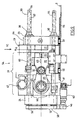
- a CD in 3.7 is used in the prior art Seconds or less. It is a machine concept of Applicant. It is a fully hydraulic machine 10 with very good properties in Terms of machine stability.
- the characteristic of the machine 10 is that Combination of a short and a long stroke.
- the short stroke (C in Figure 2) is included 70 to 80 mm.
- the closing force is approximately 600 kN.
- the maintenance stroke (D) is included about a total of 300 mm.
- a mold plate 1 is fixed to a machine stand 8 or
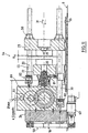
- FIG. 2 shows for the hydraulic components the solution of FIG. 1. However, FIG. 2 has a position measuring system 64 according to FIG equipped with a new solution. Figure 2 shows schematically that also a hydraulic driven machine can be controlled via the travel function.
- Figure 3 shows an example of the new solution.
- the long-stroke support plate 23 can be fixed depending on the selected concept or movably arranged on the machine stand 8, must accordingly the drive carrier plate can be fixed or movable.
- the picture side has a compact structural unit 17 a crank drive 25.
- the assembly 17 consists of a drive carrier plate 24 and a movable platen 22 which is movable on a guide rests on the machine bed 8, and a crank support structure 28 Crank drive 25 is movable on the one hand via a pin 32 Tool clamping plate 22 and on the other hand via a crank or a Eccentric articulated in the crank support structure 28 such that the Crank rod 26 can perform the crank movement according to the eccentricity.
- the eccentricity (e, Figure 11) corresponds to half the lifting height.
- the driven mold half 20 On the opposite side of the movable platen 22 is located the driven mold half 20. With the two mold halves 21 and 20 in closed state of the cavity 35 for the. Deposit the desired one disk-shaped matrices 9, 9 '( Figure 2).
- the CD is not directly in poured the cavity 35.
- a die on one or both sides 9, 9 'inserted, which as a negative mold is the cavity for the flat to be produced Has disk.
- the anchoring and holding force between the two plates is by connecting means, in particular by three or possibly four Pillars 30 ensured.
- Each column 30 is on the die plate on the die side or long-stroke support plate 23 anchored via a nut 38.
- At the Drive carrier plate 24 is attached to a rotatable collar 39, which over a Gear ring 40 engages.
- the fixed nut 38 engages on an internal thread Thread 33 of each column.
- a rotary movement of the ring gear 40 or Pinion 34 is by the rotation of the columns 30 on the nut 38 and that Thread 33 of each column 30 into a linear movement (arrows 29) of the nozzle side Tool mounting plate or long-stroke support plate 23 implemented.
- This movement represents the long or maintenance stroke and is used for quick die change and for the basic setting and cyclical correction of the same.
- the short In contrast, the working stroke is via the crank drive 25 and the movable one Tool platen 22 performed.
- Figure 3 also partially shows schematically the basic concept of the new solution for the production of flat Data carriers such as compact discs. The situation at the transition from the injection phase into the embossing phase.
- FIG. 1 sets Basic diagram with the mechanical engineering core elements of a machine central column nut drive 16.
- K means the spring constant of the column 30, optionally with inclusion of the other deformable components, insofar as the resulting deformation the distance S under a corresponding load influenced between the platen 22 or 23.
- a Drive carrier plate 24 is designated as fixed by PLfix. In this construction concept is the drive carrier plate 24 rigid or fixed to the machine bed 8 or Machine stand connected.
- a crank drive 25 with crank rod 26 as well Crank disk 27 via crank support structure 28 is on the drive carrier plate 24 firmly attached so that the corresponding retention force or the shock-like Forces are directed directly to the machine bed 8.
- the crank drive 25 is designed for the short stroke and serves to apply the embossing force.
- the platen 22 moves himself with the driven mold half 20 for the short stroke, especially for the whole injection molding cycle.
- the direction of movement is indicated by arrow 41 and the path detection by arrow 42.
- the second important function is the mobility of the platen 23 for the Long stroke via the column nut drive 16.
- the platen 23 is for this purpose slidably, depicted on rollers 37 mounted.
- Both movements for the short stroke and the long stroke are preferred over one electric motor drive ensured.
- the concept is that the Drive carrier plate 24 is fixedly connected to the stand 8. Against that are two mold halves 20, 21 relative to one another and to the machine stand 8 slidably mounted.
- the compression function (K x F) becomes at least primary due to the column expansion (K) and the effective compression force (F) determined. All other deformation factors, e.g. of the different plates.
- the Compression force determined in a variety of ways and e.g. in the first approximation the torque of the drive motor 47 are derived.
- the disadvantage is that friction factors, just like acceleration forces, falsify the result.
- the application of the sensors very much advantageous because it is slow, almost static conditions.
- a accurate registration is much easier than during a highly dynamic one Process like the embossing process.
- the electromotive drive is particularly preferably via a servo motor and the mechanical overdrive via a crank drive 95 or an eccentric 61 the path function can be derived from the crank or eccentric position ( ⁇ ) and determined according to the position detection from the control of the servo motor become. Because the end of the movement is defined by the basic setting, they are real conditions in the cavities of the molds from the path function of the movable platen 22 [f ( ⁇ )] and the compression function (K x F) defined with the highest accuracy.
- the drive means are preferred over several embossing sub-steps according to a predetermined or optimizable Speed program controlled.
- the crank or eccentric drive not only has the enormous advantage that the movement function from the Conversion of a circular movement into a linear movement geometrically with the highest Accuracy can be calculated and without additional sensors from the position of the Rotor can be derived in the servo motor.
- the effective compression factor including the Temperature parameters is taken into account in the control and regulation process. This allows the entire embossing process based on the path function via predefined programs of the electromechanical drive according to the task. The beginning and end of the program sequence are already in the basic setting as well with the corresponding setting corrections (force sensor 65) of the machine. For this reason, none are used for production operations within the stamping cycle additional sensors required.
- the new solution allows the most important Sub-parameters that have an influence on the distance relationships, directly in relevant recipes or program parts. With regard the compression, these are all possible deformations, including the Column expansion.
- the path function leaves the special, concrete drive means include.
- FIG. 4a shows a further, very advantageous design idea for the Improve control accuracy.
- the mechanical game everyone correspondingly effective, mechanically movable parts by a biasing spring 50 canceled. It is important that the biasing spring 50 acts in the same direction like the force build-up for the embossing (arrow 50 ').
- FIG. 4b shows a section through a bearing point of a column axis 56
- a seal 52 or 53 is attached to both outer sides. This allows in Include oil or grease lubrication inside for low-friction storage so that here too the demands of a long life and the increased demands of clean room manufacturing are met.
- the optimal control target for the crank drive is within approximately 180 °, as can be seen from FIG. 5b.
- Three different positions are shown in FIG. 5b: the shape is open at the angle of rotation ⁇ 1; Angle of rotation ⁇ 2 represents the embossing gap and ⁇ 3 the position at the maximum embossing force.
- the crank can be in the dead center position, preferably near the dead center.
- F (FIG. 4a) means the effective force on the deformable parts of the machine, in particular on the columns 30.
- FIG. 6 schematically shows the central column nut drive 16 for the long stroke with an electric motor 43 with drive pinion 46 and the drive for the short stroke via a drive motor 47, a gear 48 and the eccentric 61.
- Die Injection unit with plasticizing cylinder is the die mounting plate on the nozzle side 23, and both electromotive drives are the other, fixed carrier plate 24 assigned.
- the maintenance stroke is carried out with a known "mold height adjustment" by means of wheel rim 40 and gear wheels 34 on the column nuts 38 hazards.
- the rotation of the columns 30 can be done with a toothed belt , will be realized.
- box C is with R1, R2, R3, etc., indicated that any computing power installed directly on site and appropriate coordination can be carried out directly. Analogous the control connections St1, St2, St3 can be provided and a corresponding one Optimization of all control and regulation processes can be ensured.
- Figures 7a and 7b schematically show the possibility of complete Speed control / regulation, wherein the figure 7a the closing of the mold and FIG. 7b shows the embossing.
- the term control corresponds to that English expression control, which includes the first two.
- SpO, SP1, SP2, etc. are different pre-selectable embossing columns.
- FIGS. 9 to 11 is a view of FIG the side or from above and a section of the form fit 54.
- a drive carrier plate 24 On The left side of the picture is a drive carrier plate 24, on the right one Module 51 for the work or short stroke directly connected by screws 66 is.
- a die mounting plate 23 On the right half of the picture is a die mounting plate 23 arranged.
- the die-side tool platen 23 is over four on the one hand Columns 30 held opposite the drive carrier plate 24 and down on one Guided tour 55.
- Each of the four columns 30 is in the via a column nut 38
- Nozzle-finished tool platen 23 mounted such that a rotational movement the column axis 56 results in a longitudinal displacement of the mold half 21.
- FIG. 10 shows a removal robot 70 with a robot arm 71 Suction holding head 72 and a CD 73 held thereon.
- the removal robot 70 has its own electric motor 74 and is a fixed removal unit 75 connected to the machine bed. Complete coordination of the Sequence of movements between robot arm 71 and short stroke movement (KH) for the Mold opening. The coordination takes place in the millisecond range and is through suitable sensors secured so that under no circumstances a collision of the moving parts occurs.
- KH short stroke movement
- FIG. 11 shows a section VII-VII of FIG. 10.
- the central column nut drive 16 is preferably used as an actuator of the closing force control, together with a force sensor 66 as an actual value transmitter for detecting the Closing force and a control device used.
- the path is recorded by Stroke movements in the servo motor itself.
- the reproducible positions are the Control / regulation or the coordination of the different axes placed.
- the required accuracy after adjusting the maintenance stroke To be able to ensure is by a biasing device 80 in each of the driven columns 30 the mechanical and bearing play required thread canceled.
- the pressure required to cancel the game can be via springs or done pneumatically and causes a preload between the Drive carrier plate 24 and the long stroke carrier plate 23 that the game at the non-positive flank is canceled.
- eccentric 61 is the example Eccentric radius designated 25 mm, which means a total short stroke of 50 mm would allow.
- the ejection device 81 is not discussed in detail. This can e.g. be trained with pneumatic actuation and the solutions of State of the art.
Abstract
Description
Die Erfindung betrifft ein Verfahren zur Steuerung/Regelung des Prägeablaufes für die Herstellung von Präzisionsteilen, insbesondere von flachen optischen Datenträgern, mit einer Spritzgiessmaschine mit zwei Formhälften, einer angetriebenen Formhälfte sowie einer Gegenformhälfte, wobei die angetriebene Formhälfte mittels eines elektromechanischen oder hydraulischen Pägeantriebes bewegt und der Kraftschluss zwischen der angetriebenen Formhälfte und der Gegenformhälfte bei der Grundeinstellung und dem ganzen Spritzzyklus über Verbindungsmittel der Spritzgiessmaschine hergestellt wird, welche sich in Funktion des Prägekraftverlaufes dehnen und das Spaltmass zwischen der angetriebenen Formhälfte und der Gegenformhälfte entsprechend beeinflussen. Die Erfindung betrifft ferner eine Antriebs- und Steuer/Regeleinrichtung für die Formschlussseite einer elektromechanisch und/oder hydraulisch angetriebenen Spritzgiessmaschine mit einer angetriebenen Formhälfte und einer Gegenformhälfte mit steuer-/regelbarem Prägeablauf für die Herstellung von Präzisionsteilen insbesondere von flachen Datenträgern wobei der Kraftschluss zwischen der angetriebenen Formhälfte und der Gegenformhälfte über dehnbare Verbindungsmittel der Spritzgiessmaschine herstellbar ist, wobei über die Dehnbarkeit der Verbindungsmittel das Spaltmass (S) zwischen der angetriebenen Formhälfte und der Gegenformhälfte beeinflussbar ist.The invention relates to a method for controlling / regulating the embossing process for the Manufacture of precision parts, especially flat optical data carriers, with an injection molding machine with two mold halves, one driven mold half and a counter mold half, the driven mold half by means of an electromechanical or hydraulic belt drive and the frictional connection between the driven mold half and the counter mold half at the Basic setting and the entire injection cycle via the lanyard Injection molding machine is manufactured, which functions as a function of the embossing force stretch and the gap between the driven mold half and the Affect the counterform half accordingly. The invention further relates to a Drive and control device for the positive locking side of an electromechanical and / or hydraulically driven injection molding machine with a driven Mold half and a counter mold half with controllable / adjustable embossing process for the production of precision parts, especially of flat data carriers the frictional connection between the driven mold half and the counter mold half can be produced via stretchable connecting means of the injection molding machine, whereby via the elasticity of the connecting means the gap dimension (S) between the driven The mold half and the counter-mold half can be influenced.
Klassische Spritzgiessmaschinen weisen grundsätzlich zwei Formhälften auf. Die eine bewegliche, erste Formhälfte wird mittels einem Antriebssystem gegenüber einer Antriebsträgerplatte für das Formschliessen sowie das Formöffnen bewegt. Die Formbewegung kann z.B. auf Grund einer Weg-, einer Druck- und/oder einer Geschwindigkertsfunktion gesteuert werden. Die GB-PS 1 226 118 schlägt vor, den Geschwindigkeitsablauf der Formbewegung für bestimmte Abschnitte eines Giesszyklusses nach vorgegebenen Programmen zu steuern. Bei der Verwendung von Hydraulikzylindern als Antriebssystem lässt sich die Geschwindigkeit der beweglichen Formhälfte über die Oelmenge steuern und/oder regeln. Mit zusätzlichen Temperaturpararnetern kann so mit hoher Genauigkeit ein optimaler Geschwindigkeitsverlauf der bewegbaren Formhälfte sichergestellt werden. Beim klassischen Spritzgiessen werden die beiden Formhälften mit einer derart grossen Schliesskraft zusammengepresst, dass es selbst unter den höchsten Drücken der Schmelze zu keinem Öffnen der Formen kommen kann. Typisch beim klassischen Spritzgiessen ist eine länger dauernde Nachdruckphase nach Abschluss der vollständigen Formfüllung. Die Nachdruckphase wird durch die Einspritzschnecke über den Anguss im Sinne eines hydraulischen Druckes aufrechterhalten. Für die Gattung der Spritzgiessmaschinen für die Herstellung von flachen Datenträgern steht im Zentrum das Prägen und Ausprägen der Dateninformation. Besonders für die Produktion von optischen Datenträgem oder CD's werden die folgenden besonderen Phasen des Herstellzyklusses unterschieden:
- Formfüllung
- Prägen und Ausprägung der Dateninformation
- Nachdruck in der Abkühlphase zur Erhaltung der Oberflächenstruktur, auch beim Schwinden des Spritzgiessteiles.
- mold filling
- Embossing and expressing the data information
- Reprinting in the cooling phase to maintain the surface structure, even when the injection molded part shrinks.
Beim klassischen Spritzgiessen ist mit der exakten Kavität in der Spritzgiessform das fertige Spritzgiessteil definitiv festgelegt. Dagegen wird bei Spritzgiessmaschinen für das Prägen die Endform des Produktes erst durch Zusammenstossen der beiden Formhälften nach anfänglich nur teilweiser Formhohlraumfüllung erreicht. Die Prägephase ist bei der Herstellung von flachen Datenträgern die Schlüsselphase. Typisch bei der Prägephase ist ein vollflächig wirksamer Nachdruck durch Anwendung eines Kompressionsdruckes direkt über die Formhälften, wofür eine angetriebene Formhälfte gegen die Gegenformhälfte verschoben wird. Unter dem Begriff Nachdruck wird eine flächig aufgebrachte Kraft durch die eine Formhälfte verstanden. Der Nachdruck ist der sinngemässe Ersatz für das über die Einspritzdüse im klassischen Spritzgiessen eher punktuell in die Form einwirkende "hydraulische" Nachdrücken mittels Druckübertragung über die flüssige Schmelze. Die angetriebene Formhälfte wird für die Herstellung von flachen Datenträgern vor dem Einspritzen an eine vorbestimmte Position gefahren und etwa für die Zeitdauer des Einspritzens in der Position gehalten. Danach wird unter Anwendung des Kompressionsdruckes die entsprechende Platine bzw. die angetriebene erste Formhälfte an die zweite Gegenformhälfte gestossen mit der Aufbringung des Prägedruckes.In classic injection molding this is the exact cavity in the injection mold finished injection molded part definitely set. In contrast, injection molding machines for shaping the final shape of the product only when the two collide Mold halves reached after only partially filling the mold cavity. The Embossing phase is the key phase in the manufacture of flat data carriers. Typical of the embossing phase is a full-surface reprint through application a compression pressure directly over the mold halves, for which a driven The mold half is moved against the counter mold half. Under the term reprint is understood to mean a force exerted over a surface by one mold half. Of the Reprint is the analogous replacement for the classic injection nozzle Injection molding "hydraulic" pressures acting on the mold rather selectively by means of pressure transfer via the liquid melt. The driven mold half is used for the production of flat data media before injection to a predetermined position driven and for about the duration of the injection in the Position held. Then, using the compression pressure corresponding board or the driven first mold half to the second Counterform half pushed with the application of the embossing pressure.
Ein Verfahren zur schrittweisen Formung von Linsen und flachen Datenträgern aus plastifiziertem thermoplastischem Harz, unter Anwendung einer Spritzgiessmaschine, wird in der EP 0 244 783 vorgeschlagen:
- Es wird als erster Schritt ein vorvergrösserter, geschlossener Formhohlraum gebildet, der zur Aufnahme des plastifizierten Harzes geeignet ist, ohne dass es darin zu einem nennenswerten Gegendruck kommt und der ein Volumen aufweist, das grösser ist als das vom plastifizierten, zur Einspritzung vorgesehene Harz unter Normaldruck maximal eingenommene Volumen.
- In den vorvergrösserten Formhohlraum wird danach ein Volumen des plastifizierten Harzes eingespritzt, das ein wenig grösser ist als das Volumen des zu formenden Gegenstandes.
- Von der Maschine wird eine kontrollierte Kraft so angewandt, dass das Volumen des Formhohlraums reduziert wird, wodurch das darin befindliche Harz neu verteilt wird und
- die angewandte Kraft danach beibehalten wird, zumindest bis zum Erstarren des Harzes, wodurch dieses im Formhohlraum komprimiert wird.
- Der Kompressionsschritt wird jedoch schon eingeleitet, bevor der Einspritzschritt abgeschlossen ist.
- As a first step, a pre-enlarged, closed mold cavity is formed, which is suitable for receiving the plasticized resin without causing any appreciable back pressure and which has a volume which is greater than that of the plasticized resin intended for injection under normal pressure maximum volume taken up.
- A volume of the plasticized resin is then injected into the pre-enlarged mold cavity, which is a little larger than the volume of the object to be molded.
- A controlled force is applied by the machine to reduce the volume of the mold cavity, thereby redistributing the resin therein and
- the force applied is then maintained, at least until the resin solidifies, compressing it in the mold cavity.
- However, the compression step is initiated before the injection step is completed.
Die jüngere US-PS 4 917 840 schlägt für die Herstellung von flachen Präzisionsteilen wie "Recording Disk" die folgenden drei Schritte vor:
- dass eine geschwindigkeitsgesteuerte Bewegung der ersten Platine erst nach dem Einspritzen des Kunststoffes bei einer bestimmten Spaltgrösse erfolgt, und
- dass ein Geschwindigkeitsprogramm, bezogen auf aufeinanderfolgende Spaltmasse der ersten Werkzeughälfte relativ zu der zweiten Werkzeughälfte,
- und/oder bezogen auf aufeinanderfolgende Zeitintervalle der Bewegung der ersten Werkzeughälfte definiert ist.
- that a speed-controlled movement of the first board takes place only after the injection of the plastic at a certain gap size, and
- that a speed program, based on successive gap dimensions of the first tool half relative to the second tool half,
- and / or is defined based on successive time intervals of the movement of the first tool half.
Es wird somit nacheinander: erstens eine exakt vorbestimmte Spaltgrösse verlangt bzw. vorgegeben, zweitens der flüssige Kunststoff dosiert eingespritzt und drittens mit einem vorgegebenen Geschwindigkeitsprogramm die Prägung vorgenommen. Die Teilschritte für den Ablauf des Geschwindigkeitsprogrammes können entweder nach bestimmten Spaltpositionen oder Zeitintervallen erfolgen, wobei vorgesehen ist, zusätzlich einzelne Abschnitte, besonders am Ende des Prägeschrittes, druckgesteuert sicherzustellen. Voraussetzung dieser Vorschläge ist eine exakte Spaltmessung. Die Qualität der ganzen Steuerung/ Regelung ist deshalb abhängig von der Genauigkeit der momentnen Spaltmessung bzw. einer entsprechenden Auswertung in Echtzeit. Eine Spaltmessung zwischen den Matrizen wäre aufwendig, so dass in der Praxis ein Ersatzmass, z.B. eine Abstandsmessung zwischen den Formträgerplatten, vorgenommen wird, wie in der US-PS 4 917 840 vorgeschlagen wird. Eine Prägeregelung aufbauend auf dem fortlaufend gemessenen Spaltmass zwischen den beiden Formhälften beinhaltet nur die Phase der Verkleinerung des Spaltes bzw. die Phase der Materialverteilung, nicht aber die Phase des Kraftaufbaues bei der Ausprägung. Diese Lösung bedingt deshalb eine zusätzliche Kraftmessung "realtime" zur exakten Steuerung/Regelung des Prägeprozesses. Die geschwindigkeitsge-steuerte Bewegung kann gemäss Vorschlag der jüngeren Druckschrift deshalb erst nach Anfahren einer exakt definierten Stelle bzw. an einem definierten Spalt beginnen. Die Lösung gemäss US-PS 4 917 840 stellt hohe Ansprüche an die Sensortechnik mit den damit verbundenen Fehlermöglichkeiten.It is thus one after the other: First, an exactly predetermined gap size is required or predefined, secondly, the liquid plastic is injected in doses and thirdly the embossing was carried out with a predetermined speed program. The Partial steps for running the speed program can either be done after certain gap positions or time intervals take place, it being provided additionally individual sections, especially at the end of the embossing step, pressure-controlled sure. Precise gap measurement is a prerequisite for these suggestions. The The quality of the whole control system therefore depends on the accuracy the current gap measurement or a corresponding evaluation in real time. A gap measurement between the matrices would be complex, so in practice one Replacement dimension, e.g. a distance measurement between the mold carrier plates as proposed in U.S. Patent No. 4,917,840. An embossing scheme building on the continuously measured gap between the two Mold halves only include the phase of narrowing the gap or the phase the material distribution, but not the phase of the build-up of force during the expression. This solution therefore requires an additional force measurement "realtime" for exact Control of the embossing process. The speed-controlled movement can therefore, according to the proposal of the recent publication, only after a vehicle has started up start at a precisely defined point or at a defined gap. The solution according to US Pat. No. 4,917,840 places high demands on the sensor technology with the associated error opportunities.
Der Erfindung wurde nun die Aufgabe zugrunde gelegt, ein Verfahren sowie eine Vorrichtung mit einer Prozesskontrolle für den Prägeablauf zu entwickeln, welche eine hohe Genauigkeit und Reproduzierbarkelt des Endproduktes sicherstellen und mit möglichst wenig Sensorik betreibbar sind.The invention was based on the object, a method and a To develop a device with a process control for the embossing process, which a Ensure high accuracy and reproducibility of the end product and with as few sensors as possible can be operated.
Das erfindungsgemässe Verfahren ist dadurch gekennzeichnet, dass die Steuerung/Regelung während dem Prägeablauf unter Umgehung einer laufenden Messung des Spaltmasses zwischen den beiden Formhälften, auf der Basis der Wegfunktion der angetriebenen Formhälfte programmgesteuert/geregelt erfolgt.The method according to the invention is characterized in that the control / regulation during the embossing process, bypassing an ongoing measurement of the Gap between the two mold halves, based on the path function of the driven mold half is program controlled / regulated.
Die erfindungsgemässe Antriebs- und Steuereinrichtung ist dadurch gekennzeichnet, dass ein Prägeantrieb sowie eine Programmsteuerung/Regelung vorgesehen ist, Ober welche der Prägeablauf unter Umgehung einer laufenden Messung des Spaltmasses (S) zwischen den beiden Formhälften aufgrund der Wegfunktion der angetriebenen Formhälfte regel-/steuerbar ist.The drive and control device according to the invention is characterized in that that an embossing drive and a program control / regulation is provided, Ober which is the embossing process bypassing an ongoing measurement of the gap dimension (S) between the two mold halves due to the path function of the driven Half of the mold is adjustable / controllable.
Vom Erfinder ist erkannt worden, dass der Zeitpunkt des Prägebeginnes nicht primär
für die Qualität des fertigen Spritzgiessteiles entscheidend ist. Weit wichtiger für die
Produkteigenschaften ist die Art des Prägeablaufes mit optimaler Massenverteilung in
der Kavität und der anschliessende Kompressionsaufbau. In beiden genannten Lösungen
des Standes der Technik für die Herstellung von flachen Präzisionsteilen wird versucht,
durch das abschnittsweise Miteinbeziehen der angewendeten Kraft bzw. des
daraus resultierenden Druckes in die Steuerung/Regelung der Prägephase zu grosse
Abweichungen von den Zielgrössen zu vermeiden. Die EP O 244 783 will zudem die
für das Prägen angewendete Kraft wenigstens bis zum Erstarren des Harzes
beibehalten.
Bei einer konkreten Spritzgiessmaschine werden die Kompressionskräfte über
Rahmenträger bzw. Säulen gehalten und entsprechend ein Kraftschluss hergestellt.
Bei den enormen Kräften, die für das Prägen notwendig sind, ergibt sich eine
Maschinendehnung in der Grössenordnung von 0,5 mm bis zu 1 mm und mehr. Die
Dicke von Datenträgern liegt beispielsweise bei 0,4 bis 0,8 mm. Bei Anwendung der
höchsten Kräfte während dem Prägeschritt auf die bewegliche erste Formhälfte bzw.
auf die angetriebene Platte flieht die zweite Formhälfte mit der Gegenplatte um das
Mass der Maschinendehnung, das grösser sein kann als die Dicke des Datenträgers.The inventor has recognized that the time at which the embossing begins is not primarily decisive for the quality of the finished injection-molded part. The type of embossing process with optimum mass distribution in the cavity and the subsequent compression build-up are far more important for the product properties. In both of the aforementioned solutions of the prior art for the production of flat precision parts, attempts are made to avoid excessive deviations from the target sizes by including the applied force or the resulting pressure in the control / regulation of the embossing phase in sections. EP 0 244 783 also wants to maintain the force used for embossing at least until the resin solidifies.
In a concrete injection molding machine, the compression forces are held via frame supports or columns and a frictional connection is created accordingly. With the enormous forces that are necessary for embossing, the machine is stretched in the order of magnitude of 0.5 mm to 1 mm and more. The thickness of data carriers is, for example, 0.4 to 0.8 mm. When the highest forces are applied to the movable first mold half or to the driven plate during the embossing step, the second mold half with the counter plate flees by the extent of the machine expansion, which can be greater than the thickness of the data carrier.
Die neue Erfindung schlägt nun vor, die Steuerung/Regelung für den Prägeablauf zu
reduzieren:
Spritzgiessmaschinen haben Mittel für die Grundeinstellung der Maschine. Es wird
dazu auf die DE 36 31 164 verwiesen. Nach jedem Formwechsel wird vor Beginn des
ersten Spritzzyklusses die Maschine voreingestellt. Auf Grund der maximalen
Prägekraft wird die Grundschliesskraft festgelegt. Beispielsweise werden über einen
Säulenmutterantrieb die beweglichen Teile so positioniert, dass der Druck auf das
Werkzeug bei der Grundeinstellung bei geschlossenem Werkzeug (ohne Spritzling)
eine Schliesskraft leicht über der maximal für das Prägen erforderlichen Kraft erreicht.
Im Falle eines Kniehebelantriebes sind diese bei geschlossenem Werkzeug vollständig
gestreckt. Der Öffnungsweg kann von Fall zu Fall eingestellt werden. Damit sind aber
Anfang und Ende der Bewegung der angetriebenen Platte exakt definierbar.Injection molding machines have means for the basic setting of the machine. It will
refer to
Die neue Erfindung umgeht für die Steuerung/Regelung des Prägeablaufes auf elegante Weise das Problem der laufenden Messung der Maschinendehnung bzw. des Spaltmasses zwischen den Formhälften. Beide sind abhängig von der sich laufend ändernden Prägekraft. Die neue Erfindung erlaubt ferner, während der Phase des Prägeablaufes im Hinblick auf die Regeltechnik ebenfalls auf die entsprechende Sensor- und Auswerttechnik für den Prägekraftverlauf zu verzichten. Wie nachfolgend noch ausgeführt wird, lassen sich die wichtigsten Abweichungen im Extremfall von Zyklus zu Zyklus über eine zentrale Säulenmutterregelung korrigieren und werden damit über die Programmsteuerung/Regelung berücksichtigt. Dies reduziert als grossen Vorteil die Aufwendungen für teure "realtime" Sensortechnik während der Prägephase. Auf die entsprechend komplexere Regeltechnik kann verzichtet werden. Die neue Lösung gestattet die wichtigsten sich ändernden Parameter, insbesondere den Temperaturfaktor, welche Einfluss auf die Abstandsverhältnisse haben, zyklisch über den Programmablauf zu berücksichtigen. Im Hinblick auf die Kompression sind dies zuerst alle möglichen Deformationen, mit Einschluss der Säulendehnung. Die Wegfunktion schliesst die speziellen, konkreten Antriebsmittel ein. Anfang und Ende des Prägeprogrammablaufes werden gemäss der neuen Lösung bereits in der Grundeinstellung der Maschine definiert. Damit kann für den normalen Spritzbetrieb in der heikelsten Phase der Prägung auf spezielle "reatime" Sensor- und Regeltechnik verzichtet werden. Die erlaubt, über wählbare Programme den ganzen Prägeablauf auf der Basis der Wegfunktion des elektromechanischen Antriebes zu kontrollieren.The new invention avoids the control of the embossing process elegant way the problem of the ongoing measurement of the machine elongation or Gap between the mold halves. Both are dependent on the ongoing changing imprinting power. The new invention also allows during the phase of Embossing process with regard to the control technology also on the corresponding one To dispense with sensor and evaluation technology for the embossing force curve. As below the most important deviations in the extreme case can still be carried out Correct and become cycle to cycle via a central column nut control thus taken into account via the program control / regulation. This reduces as great advantage the expenses for expensive "realtime" sensor technology during the Embossing phase. The correspondingly more complex control technology can be dispensed with. The new solution allows the most important changing parameters, in particular the temperature factor, which influences the distance relationships, cyclically to be considered about the program flow. With regard to compression first all possible deformations, including column expansion. The Path function includes the special, concrete drive means. beginning and end of the embossing program sequence are already in the new solution Basic setting of the machine defined. It can be used for normal spraying operations the most delicate phase of embossing on special "reatime" sensor and control technology to be dispensed with. This allows the entire embossing process to be selected to control the basis of the path function of the electromechanical drive.
Die Erfindung erlaubt eine ganze Anzahl besonders vorteilhafter Ausgestaltungen,
wofür auf die Ansprüche 2 bis 12 sowie 14 bis 21 Bezug genommen wird. Als zur
Zeit beste Lösung kann die neue Lösung bei der Gattung von Spritzgiessmaschinen
angewendet werden, wie sie in der WO00/47389 der Anmelderin beschrieben ist. Es
handelt sich um eine Maschine mit einem sogenannten Lang- und einem Kurzhub. Der
Kurzhub genügt, um mit Greifem die CD's automatisch den geöffneten Formen zu
entnehmen. Der Langhub dient vor allem dem Matrizewechsel.The invention allows a number of particularly advantageous configurations,
for which reference is made to
Vom Markt werden CD's mit einer Vielfalt von unterschiedlichen Grundaufbauten und
eine unbeschränkte Anzahl Variationen in Bezug auf die speziell aufzuprägenden
Daten verlangt. Die einzelnen Serien sind in der Regel klein, können aber auch in die
Tausende oder Zehntausende gehen. Der unüblich rasche Wechsel der Formeinsätze
bedingt eine spezielle Gattung von Spritzgiessmaschinen. Unter Umständen ist eine
Form bzw. die entsprechende Matrize nur eine viertel oder eine halbe Stunde in der
Maschine und muss durch eine andere ersetzt werden. Die Wirtschaftlichkeit liegt
neben einer fehlerfreien Produktion vor allem in zwei fast gleichgewichtigen Faktoren:
Die Umrüstzeit geht wegen den kleinen Serien stark in die Produktivität ein, da die Matrizen pro Stunde oft mehrmals gewechselt werden müssen. Matrizen sind aus Distanz betrachtet eine Art dünne CD-Platten, welche als Negativform das Abbild der Oberflächenstruktur der CD aufweisen. Gewechselt wird somit nur die Matrizenplatte, welche in die Form einlegbar und z.B. in einer halben Minute wieder herausnehmbar ist.The changeover time has a major impact on productivity due to the small series, as the Matrices often have to be changed several times per hour. Matrices are out Distance looks at a kind of thin CD disks, which as a negative form represent the image of Have surface structure of the CD. This means that only the die plate is changed, which can be inserted into the mold and e.g. removable in half a minute is.
Die Wegfunktion wird sowohl in der ersten Phase der Verkleinerung des Prägespaltes bzw, der Materialverteilung wie in der zweiten Phase der Erhöhung der Prägekraft gleicherweise als Profilsteuerung/-regelung zu Grunde gelegt. Bevorzugt erfolgt sowohl die Verkleinerung des Prägespaltes wie auch die Erhöhung der Prägekraft geschwindigkeitsgeregelt, wobei die Phase der Verkleinerung des Prägespaltes und die nachfolgende Phase der Erhöhung der Kraft mittels einer Geschwindigkeitssteuerung, vorteilhafterweise ineinanderfliessend, durchgeführt wird. Das Prägeende wird durch eine vorwählbare Wegposition des Prägeantriebes bzw. der angetriebenen Formhälfte festgelegt, welche einer voreinstellbaren Schliesskraft und einer optimalen Kraft in der Prägeendphase entspricht. Die Voreinstellung der Maschine bzw. die entsprechende Korrekturregelung durch die zentrale Säulenmutterverstellung wird dabei so gewählt, dass während der Produktion, sowohl in der Prägephase wie auch beim anschliessenden Nachdruck, alle Kräfte über die Masse des Spritzgiessteils aufgenommen und jeder metallische Kontakt der Form- bzw. Werkzeughälften vermieden wird.The path function is used both in the first phase of reducing the embossing gap or the material distribution as in the second phase of increasing the embossing force equally used as a profile control / regulation. Preferably done both reducing the embossing gap and increasing the embossing force speed controlled, the phase of the reduction of the embossing gap and the subsequent phase of increasing the force by means of a speed control, advantageously flowing into one another. The end of embossing is determined by a pre-selectable path position of the embossing drive or the driven Mold half defined, which a pre-adjustable closing force and an optimal Force in the end of stamping phase corresponds. The default setting of the machine or the appropriate correction regulation by the central column nut adjustment chosen so that during production, both in the embossing phase and with the subsequent pressure, all forces over the mass of the injection molded part and every metallic contact of the mold or tool halves is avoided.
Gemäss einer weiteren, sehr vorteilhaften Ausgestaltung der neuen Lösung erfolgt der Nachdruckverlauf programmgesteuert/-geregelt als Profilsteuerung/Regelung der Position bzw. des Weges, entweder über der Zeitbasis, der Kraft über der Zeitbasis oder des Drehmomentes des Antriebes über der Zeitbasis, derart, dass die Oberflächenstruktur bestmöglich erhalten und dass der wirksame Nachdruck während der Kühlphase so reduziert wird, dass der innere Spannungszustand der Spritzgiessteile und damit der Brechungsindex möglichst nicht negativ beeinflusst wird. Für den Nachdruckverlauf erfolgt die Steuerung/Regelung auf der Zeitbasis, dies, um der zeitlichen Funktion der Abkühlung Rechnung zu tragen und damit die im fertigen Teil benötigte innere Struktur beim Abkühlen sicherzustellen. Je nach Anwendung kann die Profilsteuerung über den Weg der Kraft, des Drehmomentes des Antriebsmotores oder einer Kombination erfolgen.According to a further, very advantageous embodiment of the new solution Program pressure controlled as profile control / regulation of the Position or path, either over the time base, the force over the time base or the torque of the drive over the time base, such that the Preserve surface structure as best as possible and that the effective reprint during the cooling phase is reduced so that the internal stress state of the Injection molded parts and therefore the refractive index should not be negatively influenced becomes. For the reprint process, the control / regulation takes place on a time basis, this in order to take into account the temporal function of the cooling and thus the im finished part to ensure the required internal structure when cooling. Depending on Application can control the profile via the path of the force, the torque of the Drive motor or a combination.
Vorgängig einer Produktionscharge, insbesondere nach jedem Werkzeugwechsel, wird eine Grundeinstellung der Maschine vorgenommen oder diese während jedern Spritzzyklus überwacht und gegebenenfalls zyklisch korrigiert. Entsprechend der maximalen Prägekraft im Prägeablauf wird auf an sich bekannte Weise die Grundschliesskraft sowie die optimale End- und Anfangsstellung des Prägeantriebes ohne Produkt und mit vollständig geschlossenem Werkzeug festgelegt. Vorzugsweise wird bei jedem Produktionszyklus der Spitzenwert der aufgetretenen Ist-Prägekraft erfasst und entsprechende Längenänderungen der Verbindungsmittel, bedingt durch thermische Einflüsse, vorzugsweise durch einen Vergleich des Mittelwertes mehrerer Messungen mit der Sollprägekraft festgestellt und durch Korrektur einer Säulenmuttereinstellung kompensiert. Die Grundeinstellung für eine optimale Endstellung und der Langhub werden über eine Säulenmutterverstellung, vorzugsweise elektromechanisch bzw. elektromotorisch, vorgenommen. Die Wegerfassung für den Lang- bzw. Inspekthub kann durch eine Wegerfassung in einem Servomotor erfolgen, wobei die in der Schliesskraftregelung ermittelte Position der Produktionsstellung in einem nachfolgenden Zyklus wieder exakt anfahrbar und als reproduzierbare Position der Steuerung/ Regelung bzw. der Koordination der verschiedenen Achsen der Spritzgiessmaschine zu Grunde legbar ist. Ein nicht unwichtiger Punkt ist, dass das Spiel zu den bewegbaren Teilen, insbesondere des Säulenmutterantriebes, durch mechanische oder pneumatische Federmittel wirksam durch Anpressen in Prägekraftrichtung aufgehoben wird. Im Falle eines hydraulischen Antriebes wird die Wegerfassung durch entsprechende Wegsensoren sichergestellt.Preceding a production batch, especially after every tool change made a basic setting of the machine or this during each spray cycle monitored and corrected cyclically if necessary. According to the maximum The basic clamping force becomes the embossing force in the embossing process in a manner known per se as well as the optimal end and start position of the embossing drive without product and fixed with the tool completely closed. Preferably everyone Production cycle the peak value of the actual embossing force occurred and corresponding Changes in length of the connecting means due to thermal Influences, preferably by comparing the mean of several measurements determined with the target embossing force and by correcting a column nut setting compensated. The basic setting for an optimal end position and the long stroke are adjusted using a column nut adjustment, preferably electromechanically or electromotive. The path detection for the long or inspection stroke can be done by a path detection in a servo motor, the in the Closing force control determined position of the production position in a subsequent one Cycle can be started exactly again and as a reproducible position of the control / Regulation or coordination of the different axes of the injection molding machine is the basis. A not unimportant point is that the game belongs to the movable parts, especially the column nut drive, by mechanical or Pneumatic spring means effectively canceled by pressing in the direction of the embossing force becomes. In the case of a hydraulic drive, the path detection is carried out appropriate displacement sensors ensured.
Gemäss einer weiteren, sehr vorteilhaften Ausgestaltung erfolgt der Kurzhub und damit auch der Prägeantrieb elektromechanisch über einen Servomotor, mit Positionserkennung im Servomotor, auf dessen Basis die Wegfunktion des elektromechanischen Antriebes errechenbar ist. Der Kurzhub oder Prägeantrieb kann einen Kniehebel-, einen Zahnstangen-, einen Exzenter- oder einen Kurbelantrieb aufweisen, der mit der angetriebenen Formhälfte verbunden ist.According to a further, very advantageous embodiment, the short stroke and thus the embossing drive electromechanically via a servo motor Position detection in the servo motor, on the basis of which the path function of the electromechanical drive can be calculated. The short stroke or embossing drive can a toggle, a rack, an eccentric or a crank drive have, which is connected to the driven mold half.
Ist der Prägeantrieb als Exzenter- oder Kurbelantrieb ausgebildet, so wird der Exzenter- bzw. Kurbelantrieb derart ausgelegt, dass der Prägehub für die maximale Kompression in Totpunktnähe nutzbar ist und die Wegfunktion aus der Kurbel- oder Exzenterstellung (ϕ) abgeleitet und entsprechend der Positionserkennung aus der Regelung des Servomotores ermittelbar ist.If the embossing drive is designed as an eccentric or crank drive, then the Eccentric or crank drive designed so that the stamping stroke for the maximum Compression can be used close to the dead center and the path function from the crank or Eccentric position (ϕ) derived and according to the position detection from the Control of the servo motor can be determined.
Bevorzugt wird die Antriebsträgerplatte fest mit dem Maschinenständer verbunden und die angetriebene Formhälfte über den Prägeantrieb relativ zur Antriebsträgerplatte bewegbar geführt, derart, dass die Reaktionskräfte aus der Beschleunigung und Abbremsung der Formbewegungen vom Maschinenständer aufgenommen werden und deshalb die Genauigkeit, insbesondere der Prägestartposition, nicht negativ beeinflussen.The drive carrier plate is preferably firmly connected to the machine stand and the driven mold half via the embossing drive relative to the drive carrier plate movably guided, such that the reaction forces from acceleration and Deceleration of the form movements are absorbed by the machine stand and therefore the accuracy, especially the embossing start position, is not negative influence.
Vorteilhafterweise weist die Antriebs- und Steuer-/Regeleinrichtung einen zentralen Säulenmutterantrieb auf, wobei eine Gegenplatte mit der Gegenformhälfte gegenüber dem Maschinenständer verschiebbar gelagert und die Grundeinstellung der Maschine über den Säulenantrieb durchführbar ist. Dabei wird der Säulenmutterantrieb als Stellglied der Schliesskraftgrundeinstellung und der Schliesskraftregelung zusammen mit einem Kraftsensor als Istwertgeber zur Erfassung der Schliesskraft und einer Regelvorrichtung ausgebildet. Der Prägeantrieb und der zentrale Säulenmutterantrieb weisen wenigstens je einen unabhängig steuerbaren Antriebsmotor, vorzugsweise als Servomotor ausgebildet, auf, wobei die Steuer-/Regelvorrichtung mit Datenbussen mit den erforderlichen Speichern für auswählbare Rezepte bzw. Programme verbindbar ist. The drive and control / regulating device advantageously has a central one Column nut drive on, with a counter plate with the counter mold half opposite the machine stand is slidably mounted and the basic setting of the machine can be carried out via the column drive. The column nut drive is used as Actuator of the basic closing force setting and the closing force control with a force sensor as an actual value transmitter for recording the closing force and one Control device trained. The embossing drive and the central column nut drive each have at least one independently controllable drive motor, preferably as Servomotor designed, with the control device with data buses the required memory for selectable recipes or programs can be connected.
Die neue Erfindung wird nun an Hand einiger Ausführungsbeispiele mit weiteren Einzelheiten erläutert. Es zeigen:
- die
Figur 1 - eine Spritzgiessmaschine des Standes der Technik für die Herstellung von z.B. CD's mit hydraulischem Antrieb;
- die
Figur 1 - schematisch in vergrössertem Massstab die hydraulischen Antriebe für den Kurz- sowie den Langhub, entsprechend der Figur 1 a, mit einer Wegerfassung für die Prägephase gemäss neuer Lösung;
- die
Figur 3 - ein Ausführungsbeispiel gemäss der neuen Lösung mit Kurbelantrieb sowie Säulenmutterantrieb mit elektromechanischen Antrieben;
- die Figur 4a
- die Spielaufhebung für den Säulenmutterantrieb einer Lösung gemäss Figur 3;
- die Figur 4b
- die Lagerung einer Säule als Ausschnittsvergrösserung der Figur 4a;
- die Figur 5a
- drei Positionen der Exzenter- bzw. Kurbelbewegung für den Kurzhub;
- die Figur 5b
- den theoretischen Kraftverlauf am Ende der Schliessbewegung beim Aufbau der Prägekraft;
- die
Figur 6 - schematisch ein Schnitt einer Drei-Säulenmaschine, mit den Antrieben für den Kurz- und den Langhub;
- die Figuren 7a und 7b
- Sollwertverläufe: die Figur 7a für das Formschliessen, die Figur 7b für das Prägen;
- die Figuren 8a bis 8d
- die verschiedenen Abläufe der Formbewegung, dargestellt als Funktion über der Zeit: die Figur 8a die Formlage, Figur 8b die Prägekraft, Figur 8c den Spalt S und Figur 8d die Schneckenbewegung;
- die
Figur 9 - eine Ansicht einer bevorzugten Ausgestaltung einer elektrisch angetriebenen Spritzgiessmaschine für die Herstellung von Präzisionsteilen;
- die
Figur 10 - eine Ansicht von oben, gemäss Pfeil
VI der Figur 10; - die
Figur 11 - einen Schnitt IX -
IX der Figur 10.
- the figure 1
- an injection molding machine of the prior art for the production of, for example, CD's with hydraulic drive;
- the figure 1
- schematically, on an enlarged scale, the hydraulic drives for the short and long stroke, corresponding to Figure 1 a, with a path detection for the embossing phase according to the new solution;
- the figure 3
- an embodiment according to the new solution with crank drive and column nut drive with electromechanical drives;
- the figure 4a
- the elimination of play for the column nut drive of a solution according to FIG. 3;
- the figure 4b
- the storage of a column as an enlarged detail of Figure 4a;
- the figure 5a
- three positions of the eccentric or crank movement for the short stroke;
- the figure 5b
- the theoretical force curve at the end of the closing movement when the stamping force builds up;
- the figure 6
- schematically shows a section of a three-column machine, with the drives for the short and long stroke;
- Figures 7a and 7b
- Setpoint value curves: FIG. 7a for positive closing, FIG. 7b for embossing;
- Figures 8a to 8d
- the different sequences of the mold movement, represented as a function over time: FIG. 8a the mold position, FIG. 8b the embossing force, FIG. 8c the gap S and FIG. 8d the screw movement;
- the figure 9
- a view of a preferred embodiment of an electrically driven injection molding machine for the production of precision parts;
- the figure 10
- a view from above, according to arrow VI of Figure 10;
- the figure 11
- a section IX - IX of Figure 10.
Mit der bekannten Lösung gemäss Figur 1 wird im Stand der Technik eine CD in 3,7
Sekunden oder weniger hergestellt. Es handelt sich um ein Maschinenkonzept der
Anmelderin. Es ist eine vollhydraulische Maschine 10 mit sehr guten Eigenschaften in
Bezug auf die Maschinenstabilität. Das Charakteristische der Maschine 10 ist die
Kombination eines Kurz- sowie eines Langhubes. Der Kurzhub (C in Figur 2) liegt bei
70 bis 80 mm. Die Schliesskraft beträgt etwa 600 kN. Der Wartungshub (D) liegt bei
etwa total 300 mm. Eine Formplatte 1 ist fest mit einem Maschinenständer 8 bzw. With the known solution according to FIG. 1, a CD in 3.7 is used in the prior art
Seconds or less. It is a machine concept of
Applicant. It is a fully
Maschinenbett verbunden. Die Zugstangen 2 sind verschraubt mit der Formplatte 1,
wobei am anderen Ende der Zugstangen 2 ein Kolbenkopf 3 sich innerhalb eines
Zylinders 4 befindet. Die Formplatte 5 ist oberhalb der Achse X - X in einer
Produktionsstellung gezeichnet, wobei der Kolbenkopf 3 dauernd gegen eine Schulter
14 der Zugstangen 2 drückt. Mit relativ kleinen Kräften bewegt sich über zwei
Hilfszylinder 11 ein Schliesskolben 12 vor- und rückwärts über den ganzen Kurzhub
(C). Nur für das Aufbringen der grossen Schliesskraft wird der entsprechende
Oeldruck in einer Kolbenkammer 13 aufgebracht. Für den Wechsel der Matrize 9, 9' in
der Form wird der Kolben 3 von Position A zu B bewegt, um genügend Platz zu
schaffen für einen Formwechsel. Mit der gezeigten Lösung wird für das Aufbringen
der Schliesskraft nur eine kleine Oelmenge benötigt. Für einen Matrizenwechsel in den
Formhälften 20, 21 werden die drei Zylinder an den Zugstangen 2 angesteuert, und
die Formplatte 5 öffnet sich um den Lang- bzw. Wartungshub (D). Unten links ist der
Kurzhub bei geöffneter Form dargestellt. Die Maschine 10 ist in Figur 1 mit geöffneter
Schutztüre 6 mit Sicht auf den Formschluss (rechts im Bild) und den Einspritzzylinder
7 (links im Bild) dargestellt. Das Rohmaterial wird über Füllbehälter 15 der Maschine
10 zugeführt, über den Einspritzzylinder 7 erwärmt und unter Druck dosiert in die
Kavitäten der Formen gespritzt. Die Figur 2 zeigt für die hydraulischen Komponenten
die·Lösung der Figur 1. Die Figur 2 ist jedoch mit einem Wegmesssystem 64 gemäss
neuer Lösung ausgerüstet. Die Figur 2 zeigt schematisch, dass auch eine hydraulisch
angetriebene Maschine über die Wegfunktion steuer-/regelbar ist.Machine bed connected. The
Die Figur 3 zeigt ein Beispiel der neuen Lösung. Auf der linken Bildseite der Figur 3 ist
die düsenseitige Werkzeugaufspannplatte bzw. Langhubträgerplatte 23 mit einer
Gegenformhälfte 21, auf die hin, gemäss Pfeilen 31, der Einspritzzylinder 7 zu- und
wegbewegt wird. Die Langhubträgerplatte 23 kann je nach gewähltem Konzept fest
oder beweglich an dem Maschinenständer 8 angeordnet werden, entsprechend muss
die Antriebsträgerplatte fest oder beweglich angeordnet werden. Auf der rechten
Bildseite befindet sich als eine bevorzugte Lösung eine kompakte Baueinheit 17 mit
einem Kurbelantrieb 25. Die Baueinheit 17 besteht aus einer Antriebsträgerplatte 24
und einer beweglichen Werkzeugaufspannplatte 22, die auf einer Führung beweglich
auf dem Maschinenbett 8 aufliegt, sowie einer Kurbeltragkonstruktion 28. Ein
Kurbelantrieb 25 ist einerseits über einen Bolzen 32 in der beweglichen
Werkzeugaufspannplatte 22 und andererseits über einen eine Kurbel bzw. einen
Exzenter in der Kurbeltragkonstruktion 28 gelenkig gelagert, derart, dass die
Kurbelstange 26 entsprechend der Exzentrizität die Kurbelbewegung ausführen kann.
Die Exzentrizität (e, Figur 11) entspricht der halben Hubhöhe. Auf der
gegenüberliegenden Seite der beweglichen Werkzeugaufspannplatte 22 befindet sich
die angetriebene Formhälfte 20. Mit den beiden Formhälften 21 sowie 20 entsteht in
geschlossenem Zustand der Hohlraum 35 für die. Einlage der gewünschten
scheibenförmigen Matrizen 9, 9' (Figur 2). Üblicherweise wird die CD nicht direkt in
den Hohlraum 35 gegossen. In dem Hohlraum wird ein- oder beidseitig je eine Matrize
9, 9' eingelegt, welche als Negativform die Kavität für den herzustellenden flachen
Datenträger aufweist. Die Verankerungs- und Haltekraft zwischen den beiden Platten
wird durch Verbindungsmittel, insbesondere durch drei oder gegebenenfalls vier
Säulen 30 sichergestellt. Jede Säule 30 ist auf der düsenseitigen Werkzeugaufspannplatte
bzw. Langhubträgerplatte 23 über eine Mutter 38 verankert. An der
Antriebsträgerplatte 24 ist ein drehbeweglicher Bund 39 befestigt, welcher über einen
Zahnkranz 40 eingreift. Die feste Mutter 38 greift über ein Innengewinde auf das
Gewinde 33 jeder Säule ein. Eine Drehbewegung des Zahnkranzes 40 bzw. des
Zahnritzels 34 wird durch die Drehung der Säulen 30 auf die Mutter 38 und das
Gewinde 33 jeder Säulen 30 in eine Linearbewegung (Pfeile 29) der düsenseitigen
Werkzeugaufspannplatte bzw. Langhubträgerplatte 23 umgesetzt. Diese Bewegung
stellt den Lang- oder Wartungshub dar und wird beim Matrizenschnellwechsel sowie
für die Grundeinstellung und eine zyklische Korrektur derselben benötigt. Der kurze
Arbeitshub wird dagegen über den Kurbelantrieb 25 sowie die bewegliche
Werkzeugaufspannplatte 22 durchgeführt. Die Figur 3 zeigt ferner teilweise
schematisch das Grundkonzept der neuen Lösung für die Herstellung von flachen
Datenträgern wie etwa Kompaktdisks. Dargestellt ist die Lage bei dem Übergang von
der Einspritzphase in die Prägephase. Im Zentrum der beiden Formhälften ist eine
Kavität Kav, welche jedoch erst am Ende der Prägephase die äussere Form des
Datenträgers bestimmt. Im Laufe der Entwicklung des Produktions-prozesses wurden
verschiedene Konzepte verfolgt. Unveränderte Gültigkeit hat die Tatsache, dass für
die höchsten Anforderungen eine Menge der Spritzmasse dosiert in die Kavität
gespritzt wird, jedoch nur so viel, dass die Kavität nur teilweise gefüllt wird.
Vorgängig der Füllung wird durch Bewegen der angetriebenen Formhälfte 20 an die
Gegenformhälfte 21 ein vorbestimmter Kompressionsspalt gebildet. Die Menge der
Spritzmasse ist mit Ma bezeichnet. Nach Abschluss der Formfüllphase bzw. des
Einspritzvorganges wird der eigentliche Prägevorgang eingeleitet. Beim Beispiel,
gemäss Figur 3, wird dafür die angetriebene Formhälfte 20 in Richtung der Kavität
Kav. weiter bewegt und unter Aufbringen einer maximalen Prägekraft der
Formhohlraum bzw. die Kavität verkleinert und die Spritzmasse verdichtet. In älteren
Verfahren wurde der Kompressionsspalt bis auf Null aufgehoben. Gemäss der neuen
Erfindung ist erkannt worden, dass die Werkzeuge nicht auf Anschlag gefahren
werden dürfen, dass vielmehr ein Restspalt S für eine exakte Endregelung, auch nach
Abschluss der Prägung, verbleiben soll. Der Anguss ist mit dem Bezugszeichen 19
versehen, der Schneckenvorraum mit dem Bezugszeichen 18. Die Figur 3 stellt ein
Grundschema mit den maschinenbaulichen Kernelementen einer Maschine mit
zentralem Säulenmutterantrieb 16 dar. Dabei bedeutet K die Federkonstante der Säule
30, gegebenenfalls mit Einschluss der übrigen deformierbaren Bauteile, soweit die
resultierende Deformation unter einer entsprechenden Belastung die Distanz S
zwischen den Werkzeugaufspannplatten 22 bzw. 23 beeinflusst. Eine
Antriebsträgerplatte 24 ist mit PLfix als ortsfest bezeichnet. In diesem Baukonzept ist
die Antriebsträgerplatte 24 starr bzw. fix mit dem Maschinenbett 8 bzw.
Maschinenständer verbunden. Ein Kurbelantrieb 25 mit Kurbelstange 26 sowie
Kurbelscheibe 27 über Kurbeltragkonstruktion 28 ist an der Antriebsträgerplatte 24
fest angebracht, so dass die entsprechende Rückhaltekraft bzw. die stossartigen
Kräfte direkt auf das Maschinenbett 8 geleitet werden. Der Kurbelantrieb 25 ist
ausgelegt für den Kurzhub und dient dem Aufbringen der Prägekraft.Figure 3 shows an example of the new solution. On the left side of Figure 3 is
the die-side tool platen or long
Einerseits ist es die Beweglichkeit der Werkzeugaufspannplatten 22 und 23,
symbolisch mit Rollen 36 bzw. 37 markiert. Die Werkzeugaufspannplatte 22 bewegt
sich mit der angetriebenen Formhälfte 20 für den Kurzhub, insbesondere für den
ganzen Spritzgiesszyklus. Der Weg X für die angetriebene Formhälfte 20 ist eine
Funktion des Drehwinkels ϕ der Kurbel 25 von ϕ (X = f [ϕ]). Die Bewegungsrichtung
ist mit dem Pfeil 41 und die Wegerfassung mit dem Pfeil 42 angedeutet. Die zweite
wichtige Funktion ist die Bewegbarkeit der Werkzeugaufspannplatte 23 für den
Langhub über den Säulenmutterantrieb 16. Die Werkzeugaufspannplatte 23 ist für
diesen Zweck verschiebbar, bildlich dargestellt auf Rollen 37 gelagert.On the one hand, it is the mobility of the
Beide Bewegungen für den Kurzhub und den Langhub werden bevorzugt über einen
elektromotorischen Antrieb sichergestellt. Das Konzept sieht vor, dass die
Antriebsträgerplatte 24 ortsfest mit dem Ständer 8 verbunden ist. Dagegen sind die
beiden Formhälften 20, 21 relativ zueinander und zu dem Maschinenständer 8
verschiebbar gelagert. Die Kompressionsfunktion (K x F) wird zumindest primär
aufgrund der Säulendehnung (K) sowie der wirksamen Kompressionskraft (F)
ermittelt. Mit dem Faktor K können alle übrigen Verformungsfaktoren, z.B. der
verschiedenen Platten, miterfasst werden. Für die Grundeinstellung kann die
Kompressionskraft auf verschiedenste Weise ermittelt und z.B. in erster Näherung aus
dem Drehmoment des Antriebsmotores 47 abgeleitet werden. Nachteilig ist dabei,
dass Reibfaktoren, genau so wie Beschleunigungskräfte das Ergebnis verfälschen.
Bevorzugt werden geeignete Kraftsensoren aus dem Bereich der Formen oder aber
Sensoren für die Dehnung der Säulen 30 zur Ermittlung der wirksamen Kompression
bzw. der Schliesskraft zugrunde gelegt. Hier ist die Anwendung der Sensoren sehr
vorteilhaft, da es sich um langsame, beinahe statische Verhältnisse handelt. Eine
genaue Erfassung ist dabei sehr viel leichter als während einem hochdynamischen
Prozess wie dem Prägeablauf. Die Programmsteuerung 49 wird so konzipiert, dass die
Steuerung/Regelung beim Fehlen einer Kompression im Prinzip auf einer reinen
Wegfunktion erfolgt, da in diesem Fall (K = 0) für die Wegfunktion der Faktor
Säulendehnung gleich Null ist.Both movements for the short stroke and the long stroke are preferred over one
electric motor drive ensured. The concept is that the
Besonders bevorzugt erfolgt der elektromotorische Antrieb über einen Servomotor und der mechanische Übertrieb über eine Kurbelantrieb 95 oder einen Exzenter 61. Dabei kann die Wegfunktion aus der Kurbel- oder Exzenterstellung (ϕ) abgeleitet und entsprechend der Positionserkennung aus der Regelung des Servomotores ermittelt werden. Weil das Ende der Bewegung durch die Grundeinstellung definiert ist, sind die realen Verhältnisse in den Kavitäten der Giessformen aus der Wegfunktion der beweglichen Werkzeugaufspannplatte 22 [f(ϕ)] sowie der Kompressionsfunktion (K x F) mit höchster Genauigkeit definiert. Die Antriebsmittel werden bevorzugt über mehrere Prägeteilschritte nach einem vorgegebenen bzw. optimierbaren Geschwindigkeitsprogramm gesteuert. Der Kurbel- bzw. Exzenterantrieb hat nicht nur den enormen Vorteil, dass bis nahe an den Totpunkt die Bewegungsfunktion aus der Umsetzung einer Kreisbewegung in eine Linearbewegung geometrisch mit höchster Genauigkeit errechenbar und ohne zusätzliche Sensoren aus der Positionsstellung des Rotors in dem Servomotor herleitbar ist. Bei einem elektromechanischen Antrieb ist deshalb eine Steuerung/Regelung auf der Basis der Wegfunktion mit hoher Genauigkeit durchführbar. Der Faktor der wirksamen Kompression mit Einschluss des Temperaturparameters, ist im Steuer- und Regelablauf berücksichtigt. Dies erlaubt, über vorgegebene Programme den ganzen Prägeablauf auf der Basis der Wegfunktion des elektromechanischen Antriebes gemäss Aufgabenstellung exakt zu kontrollieren. Anfang und Ende des Programmablaufes sind bereits in der Grundeinstellung sowie mit den entsprechenden Einstellkorrekturen (Kraftsensor 65) der Maschine gegeben. Deshalb werden für den Produktionsbetrieb innerhalb des Prägezyklusses keine weiteren Sensoren benötigt. Die neue Lösung gestattet damit, die wichtigsten Teilparameter, welche Einfluss auf die Abstandsverhältnisse haben, direkt in entsprechenden Rezepten bzw. Programmteilen zu berücksichtigen. Im Hinblick auf die Kompression sind dies zuerst alle möglichen Deformationen, mit Einschluss der Säulendehnung. Die Wegfunktion lässt die speziellen, konkreten Antriebsmittel miteinschliessen. The electromotive drive is particularly preferably via a servo motor and the mechanical overdrive via a crank drive 95 or an eccentric 61 the path function can be derived from the crank or eccentric position (ϕ) and determined according to the position detection from the control of the servo motor become. Because the end of the movement is defined by the basic setting, they are real conditions in the cavities of the molds from the path function of the movable platen 22 [f (ϕ)] and the compression function (K x F) defined with the highest accuracy. The drive means are preferred over several embossing sub-steps according to a predetermined or optimizable Speed program controlled. The crank or eccentric drive not only has the enormous advantage that the movement function from the Conversion of a circular movement into a linear movement geometrically with the highest Accuracy can be calculated and without additional sensors from the position of the Rotor can be derived in the servo motor. With an electromechanical drive therefore control based on the path function with high Accuracy feasible. The effective compression factor including the Temperature parameters, is taken into account in the control and regulation process. This allows the entire embossing process based on the path function via predefined programs of the electromechanical drive according to the task. The beginning and end of the program sequence are already in the basic setting as well with the corresponding setting corrections (force sensor 65) of the machine. For this reason, none are used for production operations within the stamping cycle additional sensors required. The new solution allows the most important Sub-parameters that have an influence on the distance relationships, directly in relevant recipes or program parts. With regard the compression, these are all possible deformations, including the Column expansion. The path function leaves the special, concrete drive means include.
Die Figur 4a zeigt einen weiteren, sehr vorteilhaften Ausgestaltungsgedanken für die
Verbesserung der Regelgenauigkeit. Für dieses Ziel wird das mechanische Spiel aller
entsprechend wirksamen, mechanisch bewegbaren Teile durch eine Vorspannfeder 50
aufgehoben. Wichtig dabei ist, dass die Vorspannfeder 50 in die selbe Richtung wirkt
wie der Kraftaufbau für die Prägung (Pfeil 50').FIG. 4a shows a further, very advantageous design idea for the
Improve control accuracy. For this goal, the mechanical game everyone
correspondingly effective, mechanically movable parts by a biasing
Die Figur 4b zeigt einen Schnitt durch eine Lagerstelle einer Säulenachse 56. An den
beiden äusseren Seiten ist je eine Dichtung 52 bzw. 53 angebracht. Dies gestattet, im
Inneren für eine reibungsarme Lagerung eine Oel- oder Fettschmierung einzuschliessen,
so dass auch hier die Forderungen einer langen Lebensdauer sowie die
erhöhten Ansprüche der Reinraumfabrikation erfüllt sind.FIG. 4b shows a section through a bearing point of a column axis 56
A
In der Figur 5a ist mit der ausgezogenen Linie 45 der theoretische Kraftverlauf am
Ende der Schliessbewegung dargestellt. Die Linie 44 zeigt als Rechenbeispiel den
effektiven Kraftverlauf über dem Weg auf beide Formhälften auf Grund der
hook'schen Kennlinien der Verformung der Säulen sowie der Platten, bei einer CD-Schliesseinheit
mit 50mm Öffnungsweg.In FIG. 5a, the theoretical line of force is at the
Das optimale Regelziel für den Kurbelantrieb liegt innerhalb von etwa 180°, wie aus
der Figur 5b erkennbar ist. In der Figur 5b sind drei unterschiedliche Lagen dargestellt:
Beim Drehwinkel ϕ1 ist die Form offen; Drehwinkel ϕ2 stellt den Prägespalt und ϕ3
die Stellung bei der maximalen Prägekraft dar. Bei der maximalen Prägekraft kann die
Kurbel in der Totpunktlage, bevorzugt in Totpunktnähe, sein. F (Figur 4a) bedeutet die
wirksame Kraft auf die deformierbaren Teile der Maschine, insbesondere auf die
Säulen 30. Als Konsequenz aus den Relativbewegungen der beiden Formhälfen 20,
21 ergibt sich eine direkte Änderung des Distanzmasses S, je nach örtlicher Lage der
beiden Werkzeugaufspannplatten 22, 23. Die Werkzeugaufspannplatte 23 bewegt
sich mit der Funktion K • F, die Werkzeugaufspannplatte 22 mit der Funktion X = f
(ϕ). Für das Distanzmass S ergibt sich die folgende Funktion:
Für die Schliesskraftregelung wird vollinhaltlich auf die DE 36 31 164 Bezug
genommen. Diese Lösung der Anmelderin zeigt ein sehr vorteilhaftes Verfahren zum
Messen und Regeln der Schliesskraft einer Kunststoffspritzgiessmaschine mit zentral
verstellbarem, der Schliesskrafterzeugung dienenden Knieheblewerk. Als Lösung wird
vorgeschlagen, dass wenigstens während eines Teils der Betriebszeit der Maschine
die Schliesskraft für jeden Arbeitszyklus einer durch die Zahl der Zyklen
vorbestimmten Betriebsperiode gemessen und aus den Messwerten ein mittlerer Wert
berechnet wird. Eine Regelung erfolgt nur, wenn dieser mittlere Wert in einer
Schliesskraft-Regelzone ausserhalb einer den vorgegebenen Sollwert der Schliesskraft
einschliessenden Toleranzzone liegt. Die Regelung erfolgt in Schliesskraftänderungsschrrtten,
wobei für jeden auf diese Änderungsschritte folgenden Arbeitszyklus eine
Messung erfolgt und die nächste der Bestimmung des mittleren Wertes dienende
Betriebsperiode erst wieder beginnt, wenn die Messung nach einem Schliesskraftänderungsschritt
einen innerhalb der Toleranzzone liegenden Wert ergibt. Es ist ferner
in vorteilhafter Weise möglich, dieses Verfahren während der ganzen Betriebszeit oder
nur während der Anfahrphase oder nur während der anschliessenden, normalen
Arbeitsphase (in welcher in der Maschine thermisches Gleichgewicht erreicht ist)
anzuwenden. Dabei hat es sich als vorteilhaft erwiesen, die Zahl der Arbeitszyklen pro
Betriebsperiode der Anfahrphase kleiner zu wählen als jene der Betriebsperioden der
normalen Arbeitsphase. Damit kann meist erheblich grösseren und zeitlich schneller
aufeinanderfolgenden Schliesskraftabweichungen vom Sollwert während der
Anfahrphase Rechnung getragen werden.
• Regelfehler: ΔF = Temp.einflussFor the closing force control, full reference is made to
• Control error: ΔF = temperature influence
Es werden einerseits zufällige Schwankungen oder der Temperatureinfluss eliminiert und die Korrektur am Inspekt Hub als Zentral-Verstellung vorgenommen.On the one hand, random fluctuations or the influence of temperature are eliminated and the correction at the Inspekt Hub was made as a central adjustment.
Die Figur 6 zeigt schematisch den zentralen Säulenmutterantrieb 16 für den Langhub
mit einem Elektromotor 43 mit Antriebsritzel 46 sowie den Antrieb für den Kurzhub
über einen Antriebsmotor 47, ein Getriebe 48 und den Exzenter 61. Die
Einspritzeinheit mit Plastifizierzylinder ist der düsenseitigen Werkzeugaufspannplatte
23, und beide elektromotorischen Antriebe sind der anderen, festen Trägerplatte 24
zugeordnet. Der Wartungshub wird mit einer an sich bekannten "Formbauhöhenverstellung"
mittels Radkranz 40 und Zahnrädern 34 an den Säulenmuttern 38
gefahren. Als Alternative kann die Drehung der Säulen 30 mit einem Zahnriemen
. realisiert werden. Mit der Lagerung der Säulen 30 mit Wälzlagern in den Formplatten
und mit der Schmierung der Lager und der Verstellgewinde lassen sich höhere
Verstellgeschwindigkeiten und damit Umrüstungszeiten beim Wechsel der Matrize
(Stamper) 9, 9' von kleiner als 30 Sekunden erreichen. Neu wird deshalb auch für
diesen Antrieb ein Motor mit genau positionierbarer Achse, vorzugsweise ein
Servomotor mit spielarmem Getriebe, eingesetzt. Zwischen Kurbelantrieb 25 und
elektrischem Antriebsmotor 47 befindet sich ein Getriebe 89, vorzugsweise ein
Stirnradgetriebe. Mit C ist eine Steuer-/Regelintelligenz mit Speicher angedeutet,
welche der entsprechenden Motorsteuerung/ Regelung die jeweils erforderlichen
Programmabläufe bzw. Rezepte vorgibt bzw. übergibt. Im Kasten C ist mit R1, R2,
R3, usw, angedeutet, dass beliebige Rechenleistungen direkt vor Ort installiert und
entsprechende Koordinationen direkt durchgeführt werden können. Sinngemäss
können die Steuerverbindungen St1, St2, St3 vorgesehen und eine entsprechende
Optimierung aller Steuer- und Regelabläufe sichergestellt werden.FIG. 6 schematically shows the central column nut drive 16 for the long stroke
with an
Die Figuren 7a und 7b zeigen schematisch die Möglichkeit einer vollständigen Geschwindigkeitssteuerung/-regelung, wobei die Figur 7a das Schliessen der Form und die Figur 7b das Prägen darstellt. Der Begriff Steuerung/Regelung entspricht dem englischen Ausdruck control, welcher beide erstgenannten einschliesst. In beiden Phasen wird ein Geschwindigkeits-profil über dem Weg verwendet. SpO, SP1, SP2, usw. sind verschiedene vorwählbare Prägespalte. Am Prägeziel verbleibt ein Spalt von z.B. 0,02 mm.Figures 7a and 7b schematically show the possibility of complete Speed control / regulation, wherein the figure 7a the closing of the mold and FIG. 7b shows the embossing. The term control corresponds to that English expression control, which includes the first two. In both Phases use a speed profile along the way. SpO, SP1, SP2, etc. are different pre-selectable embossing columns. A gap of remains at the embossing target e.g. 0.02 mm.
Die Figuren 8a bis 8d zeigen über der Zeit qualitativ den Verlauf der wichtigsten
Parameter über der Zeit:
In der Folge wird auf die Figuren 9 bis 11 Bezug genommen, welche eine Ansicht von
der Seite bzw. von oben sowie einen Schnitt des Formschlusses 54 darstellen. Auf
der linken Bildseite ist jeweils eine Antriebsträgerplatte 24, an welcher rechts eine
Baugruppe 51 für den Arbeits- bzw. Kurzhub direkt über Schrauben 66 fest verbunden
ist. Auf der rechten Bildhälfte ist eine düsenseitige Werkzeugauf-spannplatte 23
angeordnet. Die düsenseitige Werkzeugaufspannplatte 23 ist einerseits über vier
Säulen 30 gegenüber der Antriebsträgerplatte 24 gehalten und nach unten auf einer
Führung 55 geführt. Jede der vier Säulen 30 ist über eine Säulenmutter 38 in der
düsensertigen Werkzeugaufspannplatte 23 gelagert, derart, dass eine Drehbewegung
der Säulenachse 56 eine Längsverschiebung der Formhälfte 21 ergibt. Damit die
Säulenachse 56 mit den hochpräzisen und für möglichst grosse Reibungsarmut gut
geschmierten Gewinde nicht verschmutzt wird, ist die Säulenachse 56 mit einer
Schutzhülse 57 umgeben. Die Drehbewegung der Säulenachsen 56 wird über einen
Zahnriemenantrieb 58 sowie einen Antriebsmotor bzw. Elektromotor 43 zentral
erzeugt. Die düsenseitige Werkzeugaufspannplatte 23 ist beidseits über Gleitblöcke
59 für eine reine Linearbewegung parallel zu der Achse 60 der Säulenachsen 56
nahezu spielfrei geführt; sinngemäss ist auch die bewegliche Werkzeugaufspannplatte
22 über Gleitblöcke 62 für eine exakte Parallelführung abgestützt. Der Exzenter 61 ist
frei gelagert, so dass die Kurbelbewegung des Kurbelantriebes 25 ungehindert in die
Linearbewegung umsetzbar ist. Durch das Verfahren der düsenseitigen Werkzeugaufspannplatte
23 mittels entsprechendem Drehimpuls an dem Elektromotor 43 wird die
Form weit, z.B. auf eine freie Öffnung von 300 mm, geöffnet. Die entsprechende
Bewegung ist mit Pfeil 63 angedeutet. Sämtliche temperaturbedingte Toleranzen
werden durch die Regelung der Schliesskraft korrigiert. Eine dadurch erforderliche
Korrektur wird von der Steuerung selbständig erkannt (Veränderung der Schliesskraft)
und die Positionskorrektur über den Elektromotor 43 durchgeführt. Der eigentliche
Kurzhub KH wird allein durch die Exzenterbewegung über den Kurbelantrieb 25 und
der zwangsweisen horizontalen Linearbewegung der beweglichen Werkzeugaufspannplatte
22 sichergestellt. Eine weitere zentrale Funktion in der Produktion ist die CD-Entnahme.
In der Figur 10 ist ein Entnahmeroboter 70 mit Roboterarm 71, ein
Saughaltekopf 72 sowie eine daran gehaltene CD 73 dargestellt. Der Entnahmeroboter
70 hat einen eigenen Elektromotor 74 und ist als Entnahmeeinheit 75 fest mit
dem Maschinenbett verbunden. Wichtig ist dabei eine vollständige Koordinierung des
Bewegungsablaufes zwischen Roboterarm 71 und Kurzhubbewegung (KH) für die
Formöffnung. Die Koordination erfolgt im Millisekundenbereich und ist durch
geeignete Sensoren gesichert, damit unter keinen Umständen eine Kollision der
bewegten Teile eintritt.In the following, reference is made to FIGS. 9 to 11, which is a view of FIG
the side or from above and a section of the
Die Figur 11 zeigt einen Schnitt VII - VII der Figur 10. Wie weiter oben ausgeführt ist,
wird der zentrale Säulenmutterantrieb 16 bevorzugt als Stellglied der Schliesskraftregelung,
zusammen mit einem Kraftsensor 66 als Istwertgeber zur Erfassung der
Schliesskraft und einer Regelvorrichtung genutzt. Dabei erfolgt die Wegerfassung der
Hubbewegungen im Servomotor selbst. Die reproduzierbaren Positionen werden der
Steuerung/Regelung bzw. der Koordination der verschiedenen Achsen zu Grunde
gelegt. Um die erforderliche Genauigkeit nach einer Verstellung des Wartungshubes
gewährleisten zu können, wird durch eine Vorspanneinrichtung 80 in jeder der
angetriebenen Säulen 30 das maschinenbaulich erforderliche Lager- und Gewindespiel
aufgehoben. Die erforderliche Anpressung zur Spielaufhebung kann über Federn oder
pneumatisch erfolgen und bewirkt mittels einer Vorspannkraft zwischen der
Antriebsträgerplatte 24 und der Langhubträgerplatte 23, dass das Spiel an der
kraftschlüssigen Flanke aufgehoben wird. Mit Exzenter 61 ist als Beispiel der
Exzenterradius mit 25 mm bezeichnet, was einen totalen Kurzhub von 50 mm
erlauben würde. Auf die Ausstossvorrichtung 81 wird nicht näher eingegangen. Diese
kann z.B. mit pneumatischer Betätigung ausgebildet sein und den Lösungen des
Standes der Technik entsprechen.FIG. 11 shows a section VII-VII of FIG. 10. As explained above,
the central
Claims (21)
- Method for controlling/regulating the embossing procedure for the production of precision parts, in particular of flat optical data carriers, comprising an injection moulding machine with two mould halves, a driven mould half (20) and a counter mould half (21), the driven mould half (20) being moved by means of an electromechanical or hydraulic embossing drive and the frictional connection between the driven mould half (20) and the counter mould half (21) being produced in the basic setting and during the entire injection cycle via connecting means of the injection moulding machine, which stretch as a function of the embossing force course and influence the gap mass between the driven mould half and the counter mould half, characterised in that controlling/regulating is carried out in a programme-controlled/regulated manner during the embossing procedure, while avoiding ongoing measurement of the gap mass between the two mould halves, on the basis of the path function of the driven mould half.
- Method according to claim 1, characterised in that the path function, both in the first phase of reduction of the embossing gap or material distribution and in the second phase of increasing the embossing force, are equally used as a basis for profile control/regulation.
- Method according to claim 1 or 2, characterised in that both the reduction in the embossing gap and the increase in the embossing force take place in a speed-regulated manner.
- Method according to any of claims 1 to 3, characterised in that the embossing gap reduction phase and the subsequent phase of the increase in force are carried out by means of a speed controller so as to merge.
- Method according to any of claims 1 to 4, characterised in that the embossing end is fixed by a preselectable path position of the embossing drive or of the driven mould half (20) which corresponds to a preadjustable clamping force and an optimal force in the embossing end phase.
- Method according to claim 5, characterised in that the preadjustment of the clamping force and the metering amount is selected, such that all forces are absorbed by the mass of the injection moulded part both in the embossing phase and the subsequent holding pressure and any metal contact of the mould halves (20, 21) is avoided.
- Method according to any of claims 1 to 6, characterised in that the holding pressure course is programme-controlled/regulated as a profile control/regulation of the position or path over the time basis, the force over the time basis or the torque of the drive over the time basis, in such a way that the surface structure is obtained in the best possible way and in that the effective holding pressure is reduced during the cooling phase such that the inner stress state of the injection moulded parts and therefore the refractive index is adversely affected to the least possible degree.
- Method according to any of claims 1 to 7, characterised in that the basic setting of the machine is adjusted and the basic clamping force and the optimum end and starting positions of the embossing drive without product and with completely closed mould are fixed in a manner known per se in accordance with the maximum embossing force in the embossing procedure.
- Method according to any of claims 1 to 8, characterised in that the peak value of the actual embossing force which occurred is detected during each production cycle and corresponding changes in length, in particular of the connecting means, caused by thermal influences are established, preferably by comparison of the mean value of a plurality of measurements with the desired embossing force, and are compensated by correction of the column nut setting.
- Method according to any of claims 1 to 8, characterised in that the embossing drive is driven electromechanically via a servomotor, comprising position recognition means, on the basis of which the path function of the electromechanical drive is calculated.
- Method according to any of claims 1 to 10, characterised in that the basic setting is adjusted electromechanically or by an electric motor via a column nut adjustment for an optimal end position.
- Method according to any of claims 1 to 11, characterised in that the position detection for the longitudinal or inspection stroke is preferably carried out by a displacement sensor in a servomotor, wherein the position of the production position ascertained during clamping force regulation can be exactly approached in a subsequent cycle after an inspection stroke and can be used as a basis for the reproducible position of the control/regulation or coordination of the various axes of the injection moulding machine.
- Drive and control/regulating device for the clamping mechanism-side (54) of an electromechanically and/or hydraulically driven injection moulding machine comprising a driven mould half (20) and a counter mould half (21) with controllable/regulatable embossing procedure for the production of precision parts, in particular of flat data carriers, wherein the frictional connection between the driven mould half (20) and the counter mould half (21) can be produced via stretchable connecting means of the injection moulding machine, wherein the gap mass (S) between the driven mould half (20) and the counter mould half (21) can be influenced by the stretchability of the connecting means, characterised in that an embossing drive and a programme controller/regulator (49) is provided via which the embossing procedure can be regulated/controlled while avoiding ongoing measurement of the gap mass (S) between the two mould halves (20, 21) owing to the path function of the driven mould half (20).
- Drive and control/regulating device according to claim 13, characterised in that the embossing drive comprises a toggle lever drive, a toothed rack drive, an eccentric drive or a crank drive (25) which is connected to the driven mould half (20).
- Drive and control/regulating device according to claim 14, characterised in that a drive carrier plate (24) is rigidly connected to the machine tool table or machine base (8) and the driven mould half (20) can be moved via the embossing drive relative to the drive carrier plate (24) in such a way that the reaction forces from the acceleration and deceleration of the mould movements do not adversely affect the accuracy of the embossing start position.
- Drive and control/regulating device according to any of claims 13 to 15, characterised in that the embossing drive is constructed as an eccentric or crank drive (25), the eccentric or crank drive (25) being designed in such a way that the embossing stroke can be used for maximum compression in the vicinity of the dead centre.
- Drive and control/regulating device according to any of claims 13 to 16, characterised in that the embossing drive is constructed as a crank or as a eccentric and the path function is derived from the crank or eccentric position (ϕ) and can be ascertained from the regulation of the servomotor in accordance with the position detection.
- Drive and control/regulating device according to any of claims 14 to 17, characterised in that it comprises a column nut drive (16) and a counter plate with the counter mould half (21) is displaceably mounted with respect to the machine tool table (8), wherein the basic setting of the machine can be adjusted via the column nut drive (16).
- Drive and control/regulating device according to claim 18, characterised in that a central column nut drive (16) is constructed as an actuator of the clamping force basic setting and of the clamping force regulation, together with a force sensor as actual value sensor for detecting the clamping force, and a regulating device.
- Drive and control device according to claim 13 to 19, characterised in that the play relative to the movable parts, in particular of the column nut drive (16), is preferably effectively eliminated by mechanical or pneumatic spring means by pressing in the direction of the embossing force.
- Drive and control/regulating device according to any of claims 14 to 22, characterised in that it comprises at least one respective independently controllable drive motor, preferably constructed as an electric servomotor, for the embossing drive and for the column nut drive (16), the control/regulating device being constructed with the required memories for selectable formulations or programmes.
Applications Claiming Priority (5)
| Application Number | Priority Date | Filing Date | Title |
|---|---|---|---|
| PCT/CH2000/000069 WO2000047389A1 (en) | 1999-02-10 | 2000-02-09 | Mold closing unit |
| WOPCT/CH00/00069 | 2000-02-09 | ||
| CH25322000 | 2000-12-22 | ||
| CH253200 | 2000-12-22 | ||
| PCT/CH2001/000090 WO2001058662A1 (en) | 2000-02-09 | 2001-02-09 | Method of controlling/regulating an embossing procedure and drive and control device for injection molding machines |
Publications (2)
| Publication Number | Publication Date |
|---|---|
| EP1254006A1 EP1254006A1 (en) | 2002-11-06 |
| EP1254006B1 true EP1254006B1 (en) | 2003-06-25 |
Family
ID=25705666
Family Applications (1)
| Application Number | Title | Priority Date | Filing Date |
|---|---|---|---|
| EP01902230A Expired - Lifetime EP1254006B1 (en) | 2000-02-09 | 2001-02-09 | Method of controlling/regulating an embossing procedure and drive and control device for injection molding machines |
Country Status (7)
| Country | Link |
|---|---|
| US (1) | US7097791B2 (en) |
| EP (1) | EP1254006B1 (en) |
| CN (1) | CN1192870C (en) |
| AT (1) | ATE243613T1 (en) |
| AU (1) | AU2001229946A1 (en) |
| DE (1) | DE50100334D1 (en) |
| WO (1) | WO2001058662A1 (en) |
Families Citing this family (20)
| Publication number | Priority date | Publication date | Assignee | Title |
|---|---|---|---|---|
| US6716374B2 (en) | 2000-03-30 | 2004-04-06 | Matsushita Electric Industrial Co., Ltd. | Clamp pressure control method for injection molding process |
| AT413513B (en) * | 2001-12-13 | 2006-03-15 | Engel Austria Gmbh | TWO PLATE INJECTION MOLDING |
| DE10330658A1 (en) * | 2003-07-08 | 2005-02-17 | Aweba Werkzeugbau Gmbh Aue | Method for monitoring and maintaining die cast molds comprises using sensors to monitor the temperature and progression along a die casting molded body at different positions and the deformation and/or tension progression on the body |
| WO2005032796A1 (en) * | 2003-10-06 | 2005-04-14 | Sumitomo Heavy Industries, Ltd. | Injection molding machine and injection molding method |
| CN1715033A (en) * | 2004-06-29 | 2006-01-04 | 柯尼卡美能达精密光学株式会社 | Injection mold and method for molding an optical element |
| US20070067049A1 (en) * | 2005-03-21 | 2007-03-22 | The Board Of Regents For Oklahoma State University | Method and apparatus for robust shape filter generation |
| US7875408B2 (en) * | 2007-01-25 | 2011-01-25 | International Business Machines Corporation | Bleachable materials for lithography |
| US20100078861A1 (en) * | 2007-02-15 | 2010-04-01 | Thorsten Herklotz | Method and device for blow molding containers |
| EP2357050B1 (en) * | 2010-02-10 | 2012-10-31 | Loramendi, S.COOP. | Mote molding machine |
| JP5031867B2 (en) * | 2010-05-18 | 2012-09-26 | 東芝機械株式会社 | Injection molding method and apparatus |
| GB2489754A (en) * | 2011-04-08 | 2012-10-10 | Rpc Containers Ltd | Injection moulding with delayed mould closure |
| CN104802380B (en) | 2014-01-24 | 2018-10-26 | 东芝机械株式会社 | Forming machine and its driving method |
| JP6400314B2 (en) * | 2014-03-26 | 2018-10-03 | 住友重機械工業株式会社 | Injection molding machine |
| JP5925926B1 (en) | 2015-02-19 | 2016-05-25 | 東芝機械株式会社 | Mold clamping apparatus, molding apparatus and molding method |
| CN105171701A (en) * | 2015-07-20 | 2015-12-23 | 中国科学院上海光学精密机械研究所 | High-cleanliness-degree vacuum displacement table |
| AT518638B1 (en) * | 2016-09-23 | 2017-12-15 | Engel Austria Gmbh | Injection unit for a molding machine |
| US10302598B2 (en) | 2016-10-24 | 2019-05-28 | General Electric Company | Corrosion and crack detection for fastener nuts |
| DE102016223980B4 (en) * | 2016-12-01 | 2022-09-22 | Adidas Ag | Process for the production of a plastic molding |
| CN108638466B (en) * | 2018-04-25 | 2020-03-31 | 广州市香港科大霍英东研究院 | Mold opening and closing control method, system and device of injection molding control system |
| CN110961966A (en) * | 2019-12-12 | 2020-04-07 | 广东工业大学 | Reciprocating feeding processing device with adjustable frequency and reciprocating amplitude |
Family Cites Families (16)
| Publication number | Priority date | Publication date | Assignee | Title |
|---|---|---|---|---|
| FR1539204A (en) | 1967-08-03 | 1968-09-13 | Plastimonde | Improvements to the plastic molding process by adjusting the control of the movement of the mold and the injection piston |
| US3736087A (en) * | 1969-12-23 | 1973-05-29 | Netstal Ag | Mold closing unit with separately acting rotary and fluid pressure piston drives |
| AT365119B (en) * | 1979-12-05 | 1981-12-10 | Engel Kg L | CONTROL FOR INJECTION MAKING, IN PARTICULAR LARGE-SCALE AND THIN-WALLED PLASTIC PARTS |
| CH668740A5 (en) * | 1985-11-29 | 1989-01-31 | Netstal Ag Maschf Giesserei | METHOD AND DEVICE FOR MEASURING AND REGULATING THE CLOSING FORCE OF A PLASTIC INJECTION MOLDING MACHINE. |
| US4828769A (en) | 1986-05-05 | 1989-05-09 | Galic/Maus Ventures | Method for injection molding articles |
| DE3725167C2 (en) | 1986-07-30 | 2000-08-31 | Toshiba Machine Co Ltd | Method for controlling the mold locking and compression of a plastic of an injection molding machine injected in a mold space of an injection mold and injection molding machine |
| JPS63307921A (en) * | 1987-06-10 | 1988-12-15 | Fanuc Ltd | Variable stroke type crank clamping device |
| JPH01241420A (en) * | 1988-03-24 | 1989-09-26 | Komatsu Ltd | Molding process and molding device of injection compression molding machine |
| JPH02106313A (en) * | 1988-10-14 | 1990-04-18 | Japan Steel Works Ltd:The | Injecting compression control method of electrical injection molding machine and apparatus thereof |
| JP2906349B2 (en) * | 1989-11-01 | 1999-06-21 | 住友重機械工業株式会社 | Manufacturing method of optical disk substrate |
| JP2709755B2 (en) * | 1991-06-28 | 1998-02-04 | ファナック株式会社 | Positioning correction method and correction device in electric injection molding machine |
| JPH07256722A (en) * | 1994-03-24 | 1995-10-09 | Fanuc Ltd | Injection molding control method in injection molding machine |
| ATE183131T1 (en) * | 1994-04-02 | 1999-08-15 | Karl Hehl | MOLD CLOSING UNIT FOR AN INJECTION MOLDING MACHINE AND METHOD FOR OPERATING THE SAME |
| DE69614639T2 (en) * | 1995-06-14 | 2001-12-06 | Fanuc Ltd | MOLDING TOOL CLAMPING DEVICE FOR INJECTION MOLDING MACHINE |
| US5945047A (en) * | 1997-03-13 | 1999-08-31 | The Japan Steel Works, Ltd. | Method of injection-compression molding |
| US6796783B1 (en) | 1999-02-10 | 2004-09-28 | Netsal Maschinen Ag | Mold closing unit |
-
2001
- 2001-02-09 AT AT01902230T patent/ATE243613T1/en not_active IP Right Cessation
- 2001-02-09 EP EP01902230A patent/EP1254006B1/en not_active Expired - Lifetime
- 2001-02-09 AU AU2001229946A patent/AU2001229946A1/en not_active Abandoned
- 2001-02-09 WO PCT/CH2001/000090 patent/WO2001058662A1/en active IP Right Grant
- 2001-02-09 DE DE50100334T patent/DE50100334D1/en not_active Expired - Lifetime
- 2001-02-09 US US10/203,275 patent/US7097791B2/en not_active Expired - Fee Related
- 2001-02-09 CN CN01804710.6A patent/CN1192870C/en not_active Expired - Fee Related
Also Published As
| Publication number | Publication date |
|---|---|
| US20030047827A1 (en) | 2003-03-13 |
| AU2001229946A1 (en) | 2001-08-20 |
| DE50100334D1 (en) | 2003-07-31 |
| WO2001058662A1 (en) | 2001-08-16 |
| CN1398218A (en) | 2003-02-19 |
| EP1254006A1 (en) | 2002-11-06 |
| US7097791B2 (en) | 2006-08-29 |
| CN1192870C (en) | 2005-03-16 |
| ATE243613T1 (en) | 2003-07-15 |
Similar Documents
| Publication | Publication Date | Title |
|---|---|---|
| EP1254006B1 (en) | Method of controlling/regulating an embossing procedure and drive and control device for injection molding machines | |
| DE69826330T2 (en) | Electrically actuated injection molding machine and injection molding process | |
| EP0647175B1 (en) | Injection molding machine with an electric drive and process for guiding the same | |
| DE102013017358B4 (en) | INJECTION MOLDING MACHINE WITH FUNCTION FOR ADJUSTING THE BALANCE OF THE CONNECTING BARS | |
| EP2583811B2 (en) | Method for quantifying process fluctuations in the injection process of a injection moulding machine | |
| DE102015114845B4 (en) | Method and device for injection molding plastic materials | |
| EP1150821B1 (en) | Mold closing unit | |
| EP0837764B1 (en) | Process for regulating or controlling an injection moulding machine | |
| EP0674985A1 (en) | Mould closing unit for an injection moulding unit and method for its operation | |
| WO2016203394A1 (en) | Method and device for producing mould material moulds for the casting of metals | |
| EP1343621B1 (en) | Method and device for injection moulding flat optical data supports which have a precise weight | |
| DE102006020213A1 (en) | Press for producing compacts of powder material | |
| DE69918402T2 (en) | Method for controlling the injection phase in an injection molding machine | |
| DE60104348T2 (en) | Method and device for controlling an injection molding machine suitable for reducing the weight changes of moldings | |
| DE3203810C2 (en) | Mold closing unit of an injection molding machine with a device for the controlled running of a given speed profile | |
| EP1420930B1 (en) | Method and device for the automatic production of wafers | |
| EP0461143B1 (en) | Process for controlling the dwell pressure phase during injection moulding of thermoplastics | |
| WO2003018286A1 (en) | Method and device for producing planar plastic moulded parts, in particular plastic panes | |
| EP0814924B1 (en) | Method of ensuring sand-mould quality by measuring the rate of flow of oil to the head of a press | |
| DE2906858A1 (en) | Moulding press for glass, ceramics, or plastics etc. - are produced in one operation in cavity formed by hollowed pressurised rams passing through shear ring | |
| EP1280647B1 (en) | Injection moulding machine with eccentric drive | |
| DE19529279C1 (en) | Pressure die-casting machine | |
| DE3816147C1 (en) | Device for manufacturing glass articles according to the pressing method | |
| WO2004016411A1 (en) | Device for compensating tilting forces that occur during injection compression moulding and method for producing plastic moulded parts | |
| EP1371472A1 (en) | Injection compression moulding apparatus and process and product produced thereby |
Legal Events
| Date | Code | Title | Description |
|---|---|---|---|
| PUAI | Public reference made under article 153(3) epc to a published international application that has entered the european phase |
Free format text: ORIGINAL CODE: 0009012 |
|
| 17P | Request for examination filed |
Effective date: 20020515 |
|
| AK | Designated contracting states |
Kind code of ref document: A1 Designated state(s): AT BE CH CY DE DK ES FI FR GB GR IE IT LI LU MC NL PT SE TR |
|
| AX | Request for extension of the european patent |
Free format text: AL;LT;LV;MK;RO;SI |
|
| GRAH | Despatch of communication of intention to grant a patent |
Free format text: ORIGINAL CODE: EPIDOS IGRA |
|
| GRAH | Despatch of communication of intention to grant a patent |
Free format text: ORIGINAL CODE: EPIDOS IGRA |
|
| GRAA | (expected) grant |
Free format text: ORIGINAL CODE: 0009210 |
|
| AK | Designated contracting states |
Designated state(s): AT BE CH CY DE DK ES FI FR GB GR IE IT LI LU MC NL PT SE TR |
|
| PG25 | Lapsed in a contracting state [announced via postgrant information from national office to epo] |
Ref country code: IT Free format text: LAPSE BECAUSE OF FAILURE TO SUBMIT A TRANSLATION OF THE DESCRIPTION OR TO PAY THE FEE WITHIN THE PRESCRIBED TIME-LIMIT;WARNING: LAPSES OF ITALIAN PATENTS WITH EFFECTIVE DATE BEFORE 2007 MAY HAVE OCCURRED AT ANY TIME BEFORE 2007. THE CORRECT EFFECTIVE DATE MAY BE DIFFERENT FROM THE ONE RECORDED. Effective date: 20030625 Ref country code: NL Free format text: LAPSE BECAUSE OF FAILURE TO SUBMIT A TRANSLATION OF THE DESCRIPTION OR TO PAY THE FEE WITHIN THE PRESCRIBED TIME-LIMIT Effective date: 20030625 Ref country code: GB Free format text: LAPSE BECAUSE OF FAILURE TO SUBMIT A TRANSLATION OF THE DESCRIPTION OR TO PAY THE FEE WITHIN THE PRESCRIBED TIME-LIMIT Effective date: 20030625 Ref country code: FI Free format text: LAPSE BECAUSE OF FAILURE TO SUBMIT A TRANSLATION OF THE DESCRIPTION OR TO PAY THE FEE WITHIN THE PRESCRIBED TIME-LIMIT Effective date: 20030625 Ref country code: FR Free format text: LAPSE BECAUSE OF FAILURE TO SUBMIT A TRANSLATION OF THE DESCRIPTION OR TO PAY THE FEE WITHIN THE PRESCRIBED TIME-LIMIT Effective date: 20030625 Ref country code: CY Free format text: LAPSE BECAUSE OF FAILURE TO SUBMIT A TRANSLATION OF THE DESCRIPTION OR TO PAY THE FEE WITHIN THE PRESCRIBED TIME-LIMIT Effective date: 20030625 Ref country code: TR Free format text: LAPSE BECAUSE OF FAILURE TO SUBMIT A TRANSLATION OF THE DESCRIPTION OR TO PAY THE FEE WITHIN THE PRESCRIBED TIME-LIMIT Effective date: 20030625 Ref country code: IE Free format text: LAPSE BECAUSE OF FAILURE TO SUBMIT A TRANSLATION OF THE DESCRIPTION OR TO PAY THE FEE WITHIN THE PRESCRIBED TIME-LIMIT Effective date: 20030625 |
|
| REG | Reference to a national code |
Ref country code: GB Ref legal event code: FG4D Free format text: NOT ENGLISH |
|
| REG | Reference to a national code |
Ref country code: CH Ref legal event code: EP |
|
| REG | Reference to a national code |
Ref country code: IE Ref legal event code: FG4D Free format text: GERMAN |
|
| REF | Corresponds to: |
Ref document number: 50100334 Country of ref document: DE Date of ref document: 20030731 Kind code of ref document: P |
|
| REG | Reference to a national code |
Ref country code: CH Ref legal event code: NV Representative=s name: PATENTANWALT ERNST ACKERMANN |
|
| PG25 | Lapsed in a contracting state [announced via postgrant information from national office to epo] |
Ref country code: PT Free format text: LAPSE BECAUSE OF FAILURE TO SUBMIT A TRANSLATION OF THE DESCRIPTION OR TO PAY THE FEE WITHIN THE PRESCRIBED TIME-LIMIT Effective date: 20030925 Ref country code: DK Free format text: LAPSE BECAUSE OF FAILURE TO SUBMIT A TRANSLATION OF THE DESCRIPTION OR TO PAY THE FEE WITHIN THE PRESCRIBED TIME-LIMIT Effective date: 20030925 Ref country code: SE Free format text: LAPSE BECAUSE OF FAILURE TO SUBMIT A TRANSLATION OF THE DESCRIPTION OR TO PAY THE FEE WITHIN THE PRESCRIBED TIME-LIMIT Effective date: 20030925 Ref country code: GR Free format text: LAPSE BECAUSE OF FAILURE TO SUBMIT A TRANSLATION OF THE DESCRIPTION OR TO PAY THE FEE WITHIN THE PRESCRIBED TIME-LIMIT Effective date: 20030925 |
|
| LTIE | Lt: invalidation of european patent or patent extension |
Effective date: 20030625 |
|
| NLV1 | Nl: lapsed or annulled due to failure to fulfill the requirements of art. 29p and 29m of the patents act | ||
| PG25 | Lapsed in a contracting state [announced via postgrant information from national office to epo] |
Ref country code: ES Free format text: LAPSE BECAUSE OF FAILURE TO SUBMIT A TRANSLATION OF THE DESCRIPTION OR TO PAY THE FEE WITHIN THE PRESCRIBED TIME-LIMIT Effective date: 20031222 |
|
| GBV | Gb: ep patent (uk) treated as always having been void in accordance with gb section 77(7)/1977 [no translation filed] |
Effective date: 20030625 |
|
| PG25 | Lapsed in a contracting state [announced via postgrant information from national office to epo] |
Ref country code: LU Free format text: LAPSE BECAUSE OF NON-PAYMENT OF DUE FEES Effective date: 20040209 |
|
| REG | Reference to a national code |
Ref country code: IE Ref legal event code: FD4D |
|
| PG25 | Lapsed in a contracting state [announced via postgrant information from national office to epo] |
Ref country code: BE Free format text: LAPSE BECAUSE OF NON-PAYMENT OF DUE FEES Effective date: 20040228 Ref country code: MC Free format text: LAPSE BECAUSE OF NON-PAYMENT OF DUE FEES Effective date: 20040228 |
|
| PLBE | No opposition filed within time limit |
Free format text: ORIGINAL CODE: 0009261 |
|
| STAA | Information on the status of an ep patent application or granted ep patent |
Free format text: STATUS: NO OPPOSITION FILED WITHIN TIME LIMIT |
|
| 26N | No opposition filed |
Effective date: 20040326 |
|
| EN | Fr: translation not filed | ||
| BERE | Be: lapsed |
Owner name: *NETSTAL-MASCHINEN A.G. Effective date: 20040228 |
|
| PGFP | Annual fee paid to national office [announced via postgrant information from national office to epo] |
Ref country code: AT Payment date: 20070206 Year of fee payment: 7 |
|
| PGFP | Annual fee paid to national office [announced via postgrant information from national office to epo] |
Ref country code: CH Payment date: 20070227 Year of fee payment: 7 |
|
| REG | Reference to a national code |
Ref country code: CH Ref legal event code: PL |
|
| PG25 | Lapsed in a contracting state [announced via postgrant information from national office to epo] |
Ref country code: CH Free format text: LAPSE BECAUSE OF NON-PAYMENT OF DUE FEES Effective date: 20080229 Ref country code: LI Free format text: LAPSE BECAUSE OF NON-PAYMENT OF DUE FEES Effective date: 20080229 |
|
| PG25 | Lapsed in a contracting state [announced via postgrant information from national office to epo] |
Ref country code: AT Free format text: LAPSE BECAUSE OF NON-PAYMENT OF DUE FEES Effective date: 20080209 |
|
| PGFP | Annual fee paid to national office [announced via postgrant information from national office to epo] |
Ref country code: DE Payment date: 20100219 Year of fee payment: 10 |
|
| REG | Reference to a national code |
Ref country code: DE Ref legal event code: R119 Ref document number: 50100334 Country of ref document: DE Effective date: 20110901 |
|
| PG25 | Lapsed in a contracting state [announced via postgrant information from national office to epo] |
Ref country code: DE Free format text: LAPSE BECAUSE OF NON-PAYMENT OF DUE FEES Effective date: 20110901 |