EP1568420A2 - Dispositif et méthode de commande pour une machine vibrante - Google Patents
Dispositif et méthode de commande pour une machine vibrante Download PDFInfo
- Publication number
- EP1568420A2 EP1568420A2 EP05001429A EP05001429A EP1568420A2 EP 1568420 A2 EP1568420 A2 EP 1568420A2 EP 05001429 A EP05001429 A EP 05001429A EP 05001429 A EP05001429 A EP 05001429A EP 1568420 A2 EP1568420 A2 EP 1568420A2
- Authority
- EP
- European Patent Office
- Prior art keywords
- width modulation
- modulation signal
- pulse width
- relative position
- machine
- Prior art date
- Legal status (The legal status is an assumption and is not a legal conclusion. Google has not performed a legal analysis and makes no representation as to the accuracy of the status listed.)
- Granted
Links
- 238000000034 method Methods 0.000 title claims abstract description 14
- 239000002689 soil Substances 0.000 claims abstract description 19
- 230000000694 effects Effects 0.000 claims description 3
- 238000005056 compaction Methods 0.000 abstract description 12
- 238000006073 displacement reaction Methods 0.000 description 2
- 230000000737 periodic effect Effects 0.000 description 2
- 208000010201 Exanthema Diseases 0.000 description 1
- 230000005540 biological transmission Effects 0.000 description 1
- 150000001875 compounds Chemical class 0.000 description 1
- 230000007423 decrease Effects 0.000 description 1
- 230000001419 dependent effect Effects 0.000 description 1
- 238000010586 diagram Methods 0.000 description 1
- 230000002996 emotional effect Effects 0.000 description 1
- 201000005884 exanthem Diseases 0.000 description 1
- 239000012530 fluid Substances 0.000 description 1
- 239000007788 liquid Substances 0.000 description 1
- 239000000463 material Substances 0.000 description 1
- 230000010355 oscillation Effects 0.000 description 1
- 230000010363 phase shift Effects 0.000 description 1
- 206010037844 rash Diseases 0.000 description 1
- 238000010992 reflux Methods 0.000 description 1
- 230000035939 shock Effects 0.000 description 1
Images

Classifications
-
- B—PERFORMING OPERATIONS; TRANSPORTING
- B06—GENERATING OR TRANSMITTING MECHANICAL VIBRATIONS IN GENERAL
- B06B—METHODS OR APPARATUS FOR GENERATING OR TRANSMITTING MECHANICAL VIBRATIONS OF INFRASONIC, SONIC, OR ULTRASONIC FREQUENCY, e.g. FOR PERFORMING MECHANICAL WORK IN GENERAL
- B06B1/00—Methods or apparatus for generating mechanical vibrations of infrasonic, sonic, or ultrasonic frequency
- B06B1/10—Methods or apparatus for generating mechanical vibrations of infrasonic, sonic, or ultrasonic frequency making use of mechanical energy
- B06B1/16—Methods or apparatus for generating mechanical vibrations of infrasonic, sonic, or ultrasonic frequency making use of mechanical energy operating with systems involving rotary unbalanced masses
- B06B1/161—Adjustable systems, i.e. where amplitude or direction of frequency of vibration can be varied
- B06B1/166—Where the phase-angle of masses mounted on counter-rotating shafts can be varied, e.g. variation of the vibration phase
-
- E—FIXED CONSTRUCTIONS
- E02—HYDRAULIC ENGINEERING; FOUNDATIONS; SOIL SHIFTING
- E02D—FOUNDATIONS; EXCAVATIONS; EMBANKMENTS; UNDERGROUND OR UNDERWATER STRUCTURES
- E02D3/00—Improving or preserving soil or rock, e.g. preserving permafrost soil
- E02D3/02—Improving by compacting
- E02D3/046—Improving by compacting by tamping or vibrating, e.g. with auxiliary watering of the soil
- E02D3/074—Vibrating apparatus operating with systems involving rotary unbalanced masses
-
- Y—GENERAL TAGGING OF NEW TECHNOLOGICAL DEVELOPMENTS; GENERAL TAGGING OF CROSS-SECTIONAL TECHNOLOGIES SPANNING OVER SEVERAL SECTIONS OF THE IPC; TECHNICAL SUBJECTS COVERED BY FORMER USPC CROSS-REFERENCE ART COLLECTIONS [XRACs] AND DIGESTS
- Y10—TECHNICAL SUBJECTS COVERED BY FORMER USPC
- Y10T—TECHNICAL SUBJECTS COVERED BY FORMER US CLASSIFICATION
- Y10T74/00—Machine element or mechanism
- Y10T74/18—Mechanical movements
- Y10T74/18544—Rotary to gyratory
- Y10T74/18552—Unbalanced weight
Definitions
- the invention relates to a controller for an unbalance adjusting device in a vibration machine, in particular in a device for driving direction control of a soil compaction machine.
- the invention further relates to a method for controlling an imbalance adjusting device in a vibrating machine.
- Soil compacting machines usually have Haittelplatten that deals with a specific Move frequency to compress a soil material by vertical impacts.
- the shocks are caused by vertically directed vibrations of the vibrating plate, by an opposite Unbalanced shaft pairs are generated.
- the imbalances rotate synchronously, but with opposite Direction of rotation and generate a resulting centrifugal force in a direction of vibration.
- phase shift the imbalance can be set to a desired directional vibration direction, which may differ from the vertical direction of vibration, so that in addition to the vertically directed Vibration fraction and a horizontally directed vibration component is generated.
- the horizontal directed vibration component causes a forward or backward movement of the soil compaction machine.
- the document DE 101 21 383 C2 for example, a control for an imbalance adjustment with a vibration exciter of a soil compaction machine.
- the switching valve Used to control an oil inflow from a source of pressurized oil or an oil drain to an oil return to and from the reference piston.
- the user of the soil compacting machine may use the switching valve electrically or mechanically adjust between two positions, thereby enabling the movement the adjusting cylinder in both directions to the forward or backward movement of the soil compaction machine select.
- a disadvantage of such directional control is that that transducers are required.
- a direction control for a soil compaction machine known. It includes a moving lever whose positions through a button are detected, which controls a switching valve. The switching valve controls an adjusting cylinder in a vibration generating device so that this between a starting position and a End position is moved. Depending on the position of the adjusting moves the soil compacting device in the forward or reverse direction. Also in this soil compaction machine can only a forward or backward movement are set, each by the resulting Centrifugal force is determined in the end positions of the adjusting cylinder. However, there is no possibility to set the driving speed targeted.
- This object is device-wise by a control unit for driving the control valve solved according to a pulse width modulation signal, depending on the relative position of the imbalance of the duty cycle of the pulse width modulation signal.
- the object is achieved in that the relative positions of opposite rotating imbalances in the vibratory machine are chosen to control the vibration behavior of the Adjust vibration machine by the relative position of the imbalance depending on a pulse width modulation signal is controlled.
- a controller for an imbalance adjustment device provided in a vibration machine. It has an adjusting cylinder, the is hydraulically adjustable to a relative position of counter-rotating imbalances in the vibratory machine adjust. It is a control valve provided to adjust the adjusting cylinder so that the vibration behavior of the vibration machine, in particular the vibration direction of the vibration machine, is set. It is a control unit for driving the control valve according to a Pulse width modulation signal provided to the relative position of the imbalance depending on the Set duty cycle of the pulse width modulation signal.
- a pulse width modulation signal is periodic and has two states within the period, one first state and a second state. The ratio of the time duration during the first state is taken, to the period represents the duty cycle.
- the pulse width modulation signal causes when driving the control valve that the adjusting cylinder during the first state in the direction of the first end position and during the second state towards the second end position emotional.
- the adjusting cylinder does not take the respective end position directly, but moves to this during a certain period of time. If the state of the control valve changes according to a state change of the pulse width modulation signal so the adjusting cylinder then changes the Direction of the procedure if the previously desired end position has not yet been reached.
- the Vibration direction of the vibrating machine is determined by the constant change of position of the vibrating machine Adjusting cylinder to an average.
- the control valve By switching the control valve according to the pulse width modulation signal, it is so possible to reciprocate the adjusting cylinder between two positions during the period move.
- the driving speed of the compacting machine results from the mean value the resulting from the respective positions of the adjusting cylinder speeds. It can thus the speed of travel relative to the end positions of the adjusting cylinder Driving speed can be reduced by the effective angle of inclination of the vibration direction is reduced with respect to the vertical direction of vibration.
- the control unit can thus be connected to the control valve to the adjusting cylinder according to to control a first level of the pulse width modulation signal, so that the relative position of the imbalances be adjusted in the direction of a first fixed end position and the adjusting cylinder in accordance with a second level of the pulse width modulation signal, so that the relative position the imbalances are adjusted in the direction of a second predetermined end position.
- the pulse width modulation signal during a period for a first time period the first level and for a second time duration the second level occupies.
- the sum of the first and the second time period corresponds to the period of the Pulse width modulation signal.
- control valve is with respect to the adjusting cylinder designed so that the adjusting cylinder at a duty cycle of the pulse width modulation signal of 50% and a predetermined period completely between the first and second end position is movable.
- control unit can be connected to an input unit be to adjust the pulse width modulation signal depending on a user default.
- the input unit is preferably arranged on the vibration machine so that a user the Travel speed via the input unit during operation can control.
- a soil compaction machine provided with a control according to the invention, which has a vibrating plate with imbalances is coupled to a forward or backward movement depending on the relative position of the imbalances to effect.
- a method for controlling a Unbalance adjustment provided in a vibratory machine is chosen so that the vibration behavior of the Vibrating machine can be adjusted.
- the relative position of the imbalances depends on a pulse width modulation signal controlled.
- the relative position of the imbalances controlled as a function of a pulse width modulation signal.
- the relative position of the Unbalance depending on the duty cycle of the pulse width modulation signal set.
- the relative position of the imbalances at a first level of the Pulse width modulation signal is adjusted in the direction of a first predetermined end position and that the relative position of the imbalances in the direction of a second fixed end position in a second Level of the pulse width modulation signal is adjusted.
- the relative position of the imbalances in a Duty cycle of 50% and at a predetermined period completely from the first change to the second end position is a Duty cycle of 50% and at a predetermined period completely from the first change to the second end position.
- the relative position may be at a different from the 50% duty cycle and the predetermined Change period duration at least partially in the direction of one of the defined end positions, without them during the first time period for the first level and the second time duration for the to reach the second level.
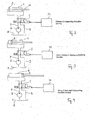
- Fig. 1 an illustration of the direction of travel control of an imbalance adjustment device
- Fig. 2 to 7 each a schematic representation of a controller for a compacting machine with a vibrating plate
- Fig. 8, 9 Characteristics of the piston rashes of an adjusting cylinder as a function of a Pulse-width modulation signal.
- FIG. 1 schematically shows the generation of a forward and rearward movement of a vibrating machine, FIG. in particular a soil compaction machine with a vibrating plate shown.
- the Vibrating plate is vibrated by rotating imbalance masses 2, which are opposite to each other Have direction of rotation.
- a resulting centrifugal force F of the imbalance masses 2 generated.
- the resulting effect Centrifugal force F in vertical direction.
- the resulting centrifugal force F is inclined to the vertical at an angle of inclination, so that beside the vertical vibration component of the resulting centrifugal force F also a horizontal Vibration component acts, which causes a driving movement of the vibration machine.
- two unbalanced shafts 1 move with the imbalance masses shown as a point 2 in opposite directions.
- the imbalance masses 2 are angularly offset to produce phase-shifted centrifugal forces arranged on the unbalanced shafts 1, so that depending on the relative position of the respective imbalances to each other, the resulting centrifugal force F more or less inclined to the vertical is.
- Fig. 1 the resulting centrifugal forces at different relative positions of the imbalance masses 2 shown. It can be seen that the resulting centrifugal force depends on the relative positions of the imbalance masses 2 may be inclined to the vertical, with a movement in the direction of the horizontal Proportion of the resulting centrifugal force is effected.
- the imbalance shafts 1 are non-rotatable by a positive force transmission means coupled, so that the directions of rotation and phase assignments are ensured.
- a Adjusting cylinder With help of a Adjusting cylinder, the relative position of the imbalance masses 2 on the imbalance shafts 1 to each other can be adjusted, as described in detail in DE 199 12 813 C1, for example.
- the driving speed of the vibration machine can not be targeted by the user be set because the piston position is not recognizable.
- the vertical amplitude of the oscillation decreases with increasing Cruising speed.
- the vibrating plate can not lift, there is no movement possible.
- the angle of inclination of the resulting centrifugal force in the direction reduce the vertical amplitude, could be achieved again a ride, as the proportion the vertical amplitude would increase.
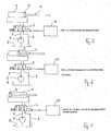
- FIGS. 2 to 7 each schematically illustrate a control for a hydraulic adjusting cylinder 4 for adjusting the relative position of imbalance masses 2 in a soil compaction machine too successive times t0 to t5.
- the machine drives in forward or reverse.
- the adjusting cylinder 4 is in an open oil circuit with a variable displacement pump 6, which has an oil flow provides, and is controlled by a control valve 5, which is designed here as a directional control valve.
- the variable displacement pump 6 takes the flow 7 from a tank 8, in which the return flow 9 back to be led.
- the volume flow is as equal and constant as possible.
- Fig. 8 shows the dependence of the piston travel in dependence from a pulse width modulation signal (PwM signal) with a pulse-duty ratio of 50%.
- Fig. 9 is a second path / time chart at a pulse-duty ratio of 80%.
- the control valve 5 is controlled by a control unit 10 with a control signal so that it according to a first level of the control signal in the first switching position and according to a second Level of the control signal is set in the second switching position.
- the control unit 10 is connected to an input device by which an operator of the Soil compaction machine, the desired movement substantially stepless or in several Can set levels according to a default value.
- the control unit 10 generates from the default value a pulse width modulation signal corresponding to the Control valve 5 is provided.
- the pulse width modulation signal is periodic and lies during a first time period at the first signal level and during a second time duration the second signal level. The sum of the first and second time periods corresponds to the period duration.
- the duty cycle gives the ratio between the duration of the first signal level to the period and the pulse-pause ratio indicates the ratio of the first time duration to the second time duration.
- the pulse width modulation signal is used to control the control valve 5 and thereby the Piston of the adjusting cylinder 4 back and forth to move.
- the period of the pulse width modulation signal is preferably selected so that at a Duty cycle of 50% of the first signal level is sufficient to complete the piston from the second Move end position to the first end position.
- the period can be between 0.5 and 2 seconds, in particular 1 second. Other values for the period are possible.
- the hydraulic system is designed so that the piston of the adjusting cylinder 4 at the duty cycle (pulse / pause ratio) of 50% between the first and second end position is moved back and forth. This corresponds to the state of vibration, since the horizontal parts of the resulting Centrifugal forces cancel each other on average and thus achieved no driving movement becomes.
Landscapes
- Engineering & Computer Science (AREA)
- Structural Engineering (AREA)
- Life Sciences & Earth Sciences (AREA)
- Agronomy & Crop Science (AREA)
- Environmental & Geological Engineering (AREA)
- Soil Sciences (AREA)
- Mechanical Engineering (AREA)
- General Life Sciences & Earth Sciences (AREA)
- Mining & Mineral Resources (AREA)
- Paleontology (AREA)
- Civil Engineering (AREA)
- General Engineering & Computer Science (AREA)
- Road Paving Machines (AREA)
- Apparatuses For Generation Of Mechanical Vibrations (AREA)
- Investigation Of Foundation Soil And Reinforcement Of Foundation Soil By Compacting Or Drainage (AREA)
Applications Claiming Priority (4)
| Application Number | Priority Date | Filing Date | Title |
|---|---|---|---|
| DE102004009841 | 2004-02-29 | ||
| DE102004009841 | 2004-02-29 | ||
| DE102004015589A DE102004015589A1 (de) | 2004-02-29 | 2004-03-30 | Steuerung und Steuerungsverfahren für eine Vibrationsmaschine |
| DE102004015589 | 2004-03-30 |
Publications (3)
| Publication Number | Publication Date |
|---|---|
| EP1568420A2 true EP1568420A2 (fr) | 2005-08-31 |
| EP1568420A3 EP1568420A3 (fr) | 2011-06-29 |
| EP1568420B1 EP1568420B1 (fr) | 2018-08-15 |
Family
ID=34751396
Family Applications (1)
| Application Number | Title | Priority Date | Filing Date |
|---|---|---|---|
| EP05001429.9A Ceased EP1568420B1 (fr) | 2004-02-29 | 2005-01-25 | Dispositif et méthode de commande pour une machine vibrante |
Country Status (4)
| Country | Link |
|---|---|
| US (1) | US7567857B2 (fr) |
| EP (1) | EP1568420B1 (fr) |
| JP (1) | JP4287828B2 (fr) |
| CN (1) | CN100403200C (fr) |
Cited By (1)
| Publication number | Priority date | Publication date | Assignee | Title |
|---|---|---|---|---|
| WO2009121606A1 (fr) * | 2008-04-03 | 2009-10-08 | Wacker Neuson Se | Plaque vibrante avec entraînement à courroie |
Families Citing this family (8)
| Publication number | Priority date | Publication date | Assignee | Title |
|---|---|---|---|---|
| DE102005029432A1 (de) * | 2005-06-24 | 2006-12-28 | Wacker Construction Equipment Ag | Bodenverdichtungsvorrichtung mit automatischer oder bedienerintuitiver Verstellung des Vorschubvektors |
| US20110158745A1 (en) * | 2009-12-31 | 2011-06-30 | Caterpillar Paving Products Inc. | Vibratory system for a compactor |
| UA99421C2 (uk) | 2011-11-18 | 2012-08-10 | Юрій Валентинович Трубянов | Генератор енергії |
| KR101523352B1 (ko) * | 2014-10-29 | 2015-05-28 | 파스코이엔지(주) | 전자 바이브레이터 |
| AT517480B1 (de) * | 2015-11-18 | 2017-02-15 | Plasser & Theurer Export Von Bahnbaumaschinen Gmbh | Stopfaggregat sowie Verfahren zum Unterstopfen eines Gleises |
| KR200480690Y1 (ko) * | 2015-12-01 | 2016-06-24 | 임광주 | 하수관 진동 세척장치 |
| KR102081435B1 (ko) * | 2018-08-09 | 2020-02-25 | (주) 에스엔지 아이시티 | 컴팩터 |
| KR102444182B1 (ko) * | 2020-09-07 | 2022-09-16 | 파스코이엔지(주) | 정현파 듀티 변조를 적용한 전자 바이브레이터 구동 알고리즘 |
Citations (1)
| Publication number | Priority date | Publication date | Assignee | Title |
|---|---|---|---|---|
| JPH05321904A (ja) | 1991-12-03 | 1993-12-07 | Ckd Corp | 空気圧シリンダにおける駆動制御方法 |
Family Cites Families (16)
| Publication number | Priority date | Publication date | Assignee | Title |
|---|---|---|---|---|
| JPS59113795A (ja) * | 1982-12-17 | 1984-06-30 | Meidensha Electric Mfg Co Ltd | 起振機の制御装置 |
| JPS59113796A (ja) * | 1982-12-17 | 1984-06-30 | Meidensha Electric Mfg Co Ltd | 起振機の制御装置 |
| US4617637A (en) * | 1985-07-09 | 1986-10-14 | Lifecare Services, Inc. | Servo control system for a reciprocating piston respirator |
| DE4343865A1 (de) * | 1993-12-22 | 1995-07-13 | Ammann Duomat Verdichtung | Bodenverdichtungsgerät |
| JPH07234727A (ja) * | 1994-02-21 | 1995-09-05 | Komatsu Ltd | 作業機の振動抑制装置およびその方法 |
| DE4434779A1 (de) * | 1994-09-29 | 1996-04-04 | Bomag Gmbh | Verfahren und Vorrichtung zum dynamischen Verdichten von Boden |
| CN2265250Y (zh) * | 1996-05-31 | 1997-10-22 | 于劲前 | 一种机械式起振机 |
| US5913915A (en) * | 1997-09-30 | 1999-06-22 | Ag-Chem Equipment Company, Inc. | Multi-variable rate dispensing system for agricultural machines |
| JP3318528B2 (ja) | 1998-05-13 | 2002-08-26 | 三笠産業株式会社 | 振動締固め機の前後進操作機構 |
| DE19903443A1 (de) * | 1999-01-29 | 2000-08-03 | Sram De Gmbh | Antriebseinheit für ein elektrisch betriebenes Fahrzeug |
| DE19912813C1 (de) | 1999-03-22 | 2000-12-21 | Wacker Werke Kg | Fahrtrichtungssteuerung für eine Bodenverdichtungsvorrichtung |
| TW470801B (en) * | 1999-03-31 | 2002-01-01 | Toshiba Corp | Drum type washing machine |
| JP3281875B2 (ja) * | 1999-10-06 | 2002-05-13 | 三菱重工業株式会社 | 振動台の波形制御装置及びその方法 |
| DE20019823U1 (de) | 2000-11-22 | 2001-02-08 | Wacker-Werke GmbH & Co KG, 80809 München | Vorrichtung zur stufenlosen Unwuchtverstellung bei lenkbaren Vibrationsplatten |
| DE10121383C2 (de) | 2001-05-02 | 2003-04-03 | Wacker Werke Kg | Steuerung für eine Unwucht-Verstelleinrichtung in einem Vibrationserreger einer Bodenverdichtungsvorrichtung |
| KR100463545B1 (ko) * | 2002-12-23 | 2004-12-29 | 엘지전자 주식회사 | 드럼세탁기 |
-
2005
- 2005-01-25 EP EP05001429.9A patent/EP1568420B1/fr not_active Ceased
- 2005-02-25 US US11/064,849 patent/US7567857B2/en not_active Expired - Fee Related
- 2005-02-25 CN CNB2005100087415A patent/CN100403200C/zh not_active Expired - Fee Related
- 2005-02-28 JP JP2005054003A patent/JP4287828B2/ja not_active Expired - Fee Related
Patent Citations (1)
| Publication number | Priority date | Publication date | Assignee | Title |
|---|---|---|---|---|
| JPH05321904A (ja) | 1991-12-03 | 1993-12-07 | Ckd Corp | 空気圧シリンダにおける駆動制御方法 |
Cited By (1)
| Publication number | Priority date | Publication date | Assignee | Title |
|---|---|---|---|---|
| WO2009121606A1 (fr) * | 2008-04-03 | 2009-10-08 | Wacker Neuson Se | Plaque vibrante avec entraînement à courroie |
Also Published As
| Publication number | Publication date |
|---|---|
| CN100403200C (zh) | 2008-07-16 |
| EP1568420B1 (fr) | 2018-08-15 |
| EP1568420A3 (fr) | 2011-06-29 |
| JP2005238235A (ja) | 2005-09-08 |
| US20050193843A1 (en) | 2005-09-08 |
| US7567857B2 (en) | 2009-07-28 |
| JP4287828B2 (ja) | 2009-07-01 |
| CN1661165A (zh) | 2005-08-31 |
Similar Documents
| Publication | Publication Date | Title |
|---|---|---|
| DE3239266C2 (fr) | ||
| DE10235976B4 (de) | Variabler Vibrationsmechanismus | |
| DE10212389B4 (de) | Geschwindigkeitssteuersystem für eine Verdichtungsarbeitsmaschine und Verfahren zur Steuerung | |
| DE102011119937A1 (de) | Verfahren und Vorrichtung zur Amplitudenverstellung einer Stampfleiste eines Straßenfertigers | |
| EP2325391A1 (fr) | Dispositif de bourrage à course variable | |
| EP1568420B1 (fr) | Dispositif et méthode de commande pour une machine vibrante | |
| DE3206591A1 (de) | Vibrationsverdichtungswalze | |
| DE10046336B4 (de) | Bodenverdichtungsvorrichtung mit Schwingungserreger und Verfahren zum Regeln des Schwingungserregers | |
| DE102016109888A1 (de) | Bodenverdichter und Verfahren zum Betreiben eines Bodenverdichters | |
| DE102017000951A1 (de) | Handgeführte Bodenverdichtungswalze mit Lenkbetriebsmodus und Verfahren zur Lenkung einer handgeführten Bodenverdichtungswalze | |
| DE19811345A1 (de) | Richtungssteuerung für Vibrationsplatte | |
| EP3789126A1 (fr) | Machine de criblage réglable | |
| EP1534439B1 (fr) | Oscillateur destine a des engins de compactage du sol | |
| DE19912813C1 (de) | Fahrtrichtungssteuerung für eine Bodenverdichtungsvorrichtung | |
| EP1757835B1 (fr) | Procédé de réglage de couple d'un embrayage | |
| DE102013021494B4 (de) | Vibrationsplatte mit einem Schwingungserreger | |
| DE102004015589A1 (de) | Steuerung und Steuerungsverfahren für eine Vibrationsmaschine | |
| DE10121383C2 (de) | Steuerung für eine Unwucht-Verstelleinrichtung in einem Vibrationserreger einer Bodenverdichtungsvorrichtung | |
| DE102007006209A1 (de) | Ferngesteuerte Rüttelplatte | |
| EP4563750A1 (fr) | Appareil de compactage du sol avec excitateur adaptatif | |
| DE948750C (de) | Einrichtung zur selbsttaetigen stufenlosen AEnderung der Arbeitsgeschwindigkeit (Drehzahl der Arbeitsspindel), insbesondere bei Drehbaenken | |
| DE2403110A1 (de) | Steuervorrichtung fuer einen vibrator | |
| DE3014534A1 (de) | Bodenverdichter | |
| DE2307351A1 (de) | Verfahren und einrichtung zur steuerung des stromes einer konstantpumpe | |
| DE2120045C3 (de) | Vorrichtung zur Erzeugung von Schwingungen mit einem hydraulischen Arbeitszylinder |
Legal Events
| Date | Code | Title | Description |
|---|---|---|---|
| PUAI | Public reference made under article 153(3) epc to a published international application that has entered the european phase |
Free format text: ORIGINAL CODE: 0009012 |
|
| AK | Designated contracting states |
Kind code of ref document: A2 Designated state(s): AT BE BG CH CY CZ DE DK EE ES FI FR GB GR HU IE IS IT LI LT LU MC NL PL PT RO SE SI SK TR |
|
| AX | Request for extension of the european patent |
Extension state: AL BA HR LV MK YU |
|
| PUAL | Search report despatched |
Free format text: ORIGINAL CODE: 0009013 |
|
| AK | Designated contracting states |
Kind code of ref document: A3 Designated state(s): AT BE BG CH CY CZ DE DK EE ES FI FR GB GR HU IE IS IT LI LT LU MC NL PL PT RO SE SI SK TR |
|
| AX | Request for extension of the european patent |
Extension state: AL BA HR LV MK YU |
|
| 17P | Request for examination filed |
Effective date: 20111229 |
|
| AKX | Designation fees paid |
Designated state(s): DE GB SE |
|
| 17Q | First examination report despatched |
Effective date: 20120411 |
|
| GRAP | Despatch of communication of intention to grant a patent |
Free format text: ORIGINAL CODE: EPIDOSNIGR1 |
|
| RIC1 | Information provided on ipc code assigned before grant |
Ipc: E02D 3/074 19800101ALI20180309BHEP Ipc: B06B 1/16 19680901AFI20180309BHEP |
|
| INTG | Intention to grant announced |
Effective date: 20180406 |
|
| GRAS | Grant fee paid |
Free format text: ORIGINAL CODE: EPIDOSNIGR3 |
|
| GRAA | (expected) grant |
Free format text: ORIGINAL CODE: 0009210 |
|
| AK | Designated contracting states |
Kind code of ref document: B1 Designated state(s): DE GB SE |
|
| REG | Reference to a national code |
Ref country code: GB Ref legal event code: FG4D Free format text: NOT ENGLISH |
|
| REG | Reference to a national code |
Ref country code: DE Ref legal event code: R096 Ref document number: 502005015877 Country of ref document: DE |
|
| PG25 | Lapsed in a contracting state [announced via postgrant information from national office to epo] |
Ref country code: SE Free format text: LAPSE BECAUSE OF FAILURE TO SUBMIT A TRANSLATION OF THE DESCRIPTION OR TO PAY THE FEE WITHIN THE PRESCRIBED TIME-LIMIT Effective date: 20180815 |
|
| RIC2 | Information provided on ipc code assigned after grant |
Ipc: B06B 1/16 20060101AFI20180309BHEP Ipc: E02D 3/074 20060101ALI20180309BHEP |
|
| REG | Reference to a national code |
Ref country code: DE Ref legal event code: R097 Ref document number: 502005015877 Country of ref document: DE |
|
| PLBE | No opposition filed within time limit |
Free format text: ORIGINAL CODE: 0009261 |
|
| STAA | Information on the status of an ep patent application or granted ep patent |
Free format text: STATUS: NO OPPOSITION FILED WITHIN TIME LIMIT |
|
| 26N | No opposition filed |
Effective date: 20190516 |
|
| PGFP | Annual fee paid to national office [announced via postgrant information from national office to epo] |
Ref country code: DE Payment date: 20200124 Year of fee payment: 16 Ref country code: GB Payment date: 20200127 Year of fee payment: 16 |
|
| REG | Reference to a national code |
Ref country code: DE Ref legal event code: R119 Ref document number: 502005015877 Country of ref document: DE |
|
| GBPC | Gb: european patent ceased through non-payment of renewal fee |
Effective date: 20210125 |
|
| PG25 | Lapsed in a contracting state [announced via postgrant information from national office to epo] |
Ref country code: GB Free format text: LAPSE BECAUSE OF NON-PAYMENT OF DUE FEES Effective date: 20210125 Ref country code: DE Free format text: LAPSE BECAUSE OF NON-PAYMENT OF DUE FEES Effective date: 20210803 |