EP1567991B1 - Method and device for verifying valuable documents - Google Patents
Method and device for verifying valuable documents Download PDFInfo
- Publication number
- EP1567991B1 EP1567991B1 EP03767703A EP03767703A EP1567991B1 EP 1567991 B1 EP1567991 B1 EP 1567991B1 EP 03767703 A EP03767703 A EP 03767703A EP 03767703 A EP03767703 A EP 03767703A EP 1567991 B1 EP1567991 B1 EP 1567991B1
- Authority
- EP
- European Patent Office
- Prior art keywords
- measuring
- vector
- reference vectors
- measuring vector
- previous
- Prior art date
- Legal status (The legal status is an assumption and is not a legal conclusion. Google has not performed a legal analysis and makes no representation as to the accuracy of the status listed.)
- Expired - Lifetime
Links
- 238000000034 method Methods 0.000 title claims abstract description 34
- 239000013598 vector Substances 0.000 claims abstract description 153
- 230000005855 radiation Effects 0.000 claims abstract description 35
- 238000004020 luminiscence type Methods 0.000 claims abstract description 33
- 239000000126 substance Substances 0.000 claims abstract description 8
- 230000003595 spectral effect Effects 0.000 claims description 44
- 238000005259 measurement Methods 0.000 claims description 39
- 238000011156 evaluation Methods 0.000 claims description 21
- 238000000926 separation method Methods 0.000 claims description 6
- 230000001419 dependent effect Effects 0.000 claims description 4
- 230000001678 irradiating effect Effects 0.000 claims 1
- 238000012360 testing method Methods 0.000 description 12
- 238000010606 normalization Methods 0.000 description 4
- 238000001228 spectrum Methods 0.000 description 4
- PXFBZOLANLWPMH-UHFFFAOYSA-N 16-Epiaffinine Natural products C1C(C2=CC=CC=C2N2)=C2C(=O)CC2C(=CC)CN(C)C1C2CO PXFBZOLANLWPMH-UHFFFAOYSA-N 0.000 description 3
- 230000015572 biosynthetic process Effects 0.000 description 2
- 238000001514 detection method Methods 0.000 description 2
- 238000010586 diagram Methods 0.000 description 2
- 238000000295 emission spectrum Methods 0.000 description 2
- 230000036962 time dependent Effects 0.000 description 2
- 230000007704 transition Effects 0.000 description 2
- 102100035971 Molybdopterin molybdenumtransferase Human genes 0.000 description 1
- 101710119577 Molybdopterin molybdenumtransferase Proteins 0.000 description 1
- 238000004458 analytical method Methods 0.000 description 1
- 238000013459 approach Methods 0.000 description 1
- 230000005540 biological transmission Effects 0.000 description 1
- 238000000354 decomposition reaction Methods 0.000 description 1
- 230000007423 decrease Effects 0.000 description 1
- 238000000151 deposition Methods 0.000 description 1
- 238000013461 design Methods 0.000 description 1
- 238000011161 development Methods 0.000 description 1
- 230000018109 developmental process Effects 0.000 description 1
- 230000004069 differentiation Effects 0.000 description 1
- 230000002452 interceptive effect Effects 0.000 description 1
- 238000001748 luminescence spectrum Methods 0.000 description 1
- 239000000203 mixture Substances 0.000 description 1
- 238000012545 processing Methods 0.000 description 1
- 238000011144 upstream manufacturing Methods 0.000 description 1
Images
Classifications
-
- G—PHYSICS
- G07—CHECKING-DEVICES
- G07D—HANDLING OF COINS OR VALUABLE PAPERS, e.g. TESTING, SORTING BY DENOMINATIONS, COUNTING, DISPENSING, CHANGING OR DEPOSITING
- G07D7/00—Testing specially adapted to determine the identity or genuineness of valuable papers or for segregating those which are unacceptable, e.g. banknotes that are alien to a currency
- G07D7/06—Testing specially adapted to determine the identity or genuineness of valuable papers or for segregating those which are unacceptable, e.g. banknotes that are alien to a currency using wave or particle radiation
- G07D7/12—Visible light, infrared or ultraviolet radiation
- G07D7/1205—Testing spectral properties
-
- G—PHYSICS
- G07—CHECKING-DEVICES
- G07D—HANDLING OF COINS OR VALUABLE PAPERS, e.g. TESTING, SORTING BY DENOMINATIONS, COUNTING, DISPENSING, CHANGING OR DEPOSITING
- G07D7/00—Testing specially adapted to determine the identity or genuineness of valuable papers or for segregating those which are unacceptable, e.g. banknotes that are alien to a currency
- G07D7/003—Testing specially adapted to determine the identity or genuineness of valuable papers or for segregating those which are unacceptable, e.g. banknotes that are alien to a currency using security elements
- G07D7/0034—Testing specially adapted to determine the identity or genuineness of valuable papers or for segregating those which are unacceptable, e.g. banknotes that are alien to a currency using security elements using watermarks
Definitions
- the invention relates to a method and a device for checking documents of value having an authenticity feature in the form of at least one luminescent substance, wherein the document of value is irradiated with light and the luminescence radiation emanating from the document of value is detected in a spectrally resolved manner in order to determine whether the authenticity feature in the checked document of value actually exists is available.
- a luminescent e.g. a fluorescent or phosphorescent authenticity feature a single substance or a mixture of several substances understood that show a luminescence.
- US 5 678 677 A discloses a classification scheme for recognizing and classifying banknotes, based on the classification of n-dimensional measurement vectors in the scanning of spectral regions.
- the present invention is thus based on the finding that a simple and reliable distinction between different authenticity features can best be obtained if a measurement vector is formed from the measured values which correspond to different frequencies and / or frequency ranges of the luminescence radiation, and a class assignment of Measuring vector to one of a plurality of predetermined reference vectors that correspond to different authenticity characteristics, characterized in that the reference vectors each at least one class assignment area is assigned and checked, in which class assignment area is the measurement vector.
- the measuring vector can consist of the measured values per se and / or variables derived therefrom.
- the determination of the class assignment regions and thus the class assignment from the measuring vector to one of the reference vectors can preferably be carried out by a comparison of the measuring vector with a plurality of reference vectors or with at least one variable, which depends on at least two reference vectors.
- a particularly preferred example of the former variant may be that the authenticity feature whose reference vector has the smallest difference, such as the smallest distance to the measuring vector, is determined or determinable as being present in the value document to be tested.
- This approach has especially with authenticity features a very similar spectral course proved to be much more suitable than a procedure in which it is checked whether the intensity and / or the course of a measured luminescence radiation differs only by a maximum of a predetermined value of the intensity or the course of a reference radiation.
- the second-mentioned variant in which no comparison of the measuring vector with each individual reference vector itself, but with at least one derived from at least two reference vectors size is performed significantly reduces the computational effort and is therefore particularly advantageous when it comes to high test speeds.
- the size which depends on at least two reference vectors, serves as a separation surface between the two reference vectors, e.g. a (n-1) dimensional hyperplane is formed between the two n-dimensional reference vectors, the separation surface separating the class assignment regions of the two reference vectors. In this case, e.g. determines the position of the measuring vector with respect to the separating surface.
- the test system according to the invention can preferably be extended to include a further step, in which it is checked whether the magnitude of the measurement vector is greater than a predetermined reference value or not.
- This step is particularly preferably performed prior to the step of assigning the class assignment areas and / or the step of checking in which of these areas the measurement vector is located.
- the measuring vector is thus preferably formed from measured values of the infrared spectral range.
- the measuring vector and the reference vectors are normalized in a similar manner.
- this can be done, for example, by normalizing to an n-1 dimensional unit sphere, so that the magnitude of all normalized vectors is the same, i.e., the same. in particular has the value 1.
- the measurements have a background signal, which does not originate from the luminescence radiation and superimposes the luminescence radiation.
- This background signal interferes with the evaluation, since the ratios of the measuring vectors to the reference vectors change significantly as a function of the height of the background signals due to the normalization and can thus lead to less accurate results of the evaluation.
- a background signal is taken into account in the evaluation of the measured values, which does not originate from the Lunünzenzstrahlung.
- an amount may be deducted from the measured values to form the measuring vector, which amount depends on the size of the background signal.
- the amount may vary from measured value to measured value of the measuring vector, i. it is also possible to use a background vector generated by the background signal.
- the amount will be particularly preferably dependent on the size of a minimum and / or maximum of the measured values and / or a ratio of a plurality of measured values to one another. If the emission spectrum of the background signal is known, by measuring the background signal at a single or e.g. a few frequencies of the background vector are calculated. If the background vector is known, it can e.g. stored in the sensor stored and be deducted without measurement of the measured values.
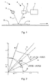
- FIG. 1 is a schematic view of a test apparatus according to a first embodiment
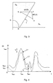
- the FIG. 2 shows a two-dimensional representation for illustrating the method according to the invention
- the FIG. 3 shows a two-dimensional representation to illustrate the class assignment method according to the invention
- FIG. 4 shows a schematic view of a spectral curve L1 measured by a banknote and of a portion L2 of the spectral curve L1 that is due only to the luminescence radiation.
- test system can be used in all devices which check luminescent authenticity features.
- banknote processing devices which can serve, for example, for counting, sorting, depositing and / or paying out banknotes.
- FIG. 1 illustrates in particular a device 1 which, in addition to components already known per se, which are not shown, also has, among other things, a transport device 2 by means of which banknotes 3 are occasionally transported past a checking device 4.
- the checking device 4 can be designed to check the authenticity, the state or the nominal value of the banknotes 3.
- the test device 4 has a light source 5, a spectral sensor 6 and an evaluation device 7, which is connected via a signal line 8 at least with the spectral sensor 6.
- the light source 5 serves to irradiate the banknote 3 with light beams 9 at an oblique angle to the banknote surface and the spectral sensor 6 for detecting and spectral decomposition of the remitted from the banknote surface radiation 10.
- the spectral sensor 6 detects by means of a spectrometer 6 luminescence 10 in the infrared Spectral range.
- the signals detected by the spectral sensor 6 are transmitted via the signal line 8 to the computer-based evaluation device 7, which checks on the basis of the measured signals whether a specific authenticity feature is present in the banknote 3.
- the device 1 is distinguished, in particular, by the type of evaluation of the measurement signals in the evaluation device 7. This can be done, for example, according to an embodiment of the method according to the invention in the following manner:
- measuring vector X (x 1 ,..., X n ) be, for example, a measure of the spectral curve of the recorded luminescent radiation 10 of the banknote 3, where x 1 to x n are values which, on the basis of the measuring signals of n different photocells of the Spectral sensors 6 are formed.
- the spectral values x 1 to x n can preferably correspond to the measured luminescence intensity at different frequencies or frequency ranges in an invisible to the eye, such as ultraviolet or particularly preferably infrared spectral range.
- the measuring vector X thus represents, at least in the case n> 1, preferably n ⁇ 5 or n ⁇ 10; a measure of the shape, ie the course of the measured spectral curve.
- the banknote In order to decide whether at all one of the two allowed authenticity features is present in or on the banknote, it can first be checked whether the magnitude of the measurement vector X, i.
- the threshold can be 0, but is preferably chosen so that counterfeits without authenticity feature are already distinguishable here certainly.
- this reference value R has, for example, an amount
- counterfeits can be sorted out, in which the authenticity features are present in themselves, but in too low a concentration. This is particularly preferred because in the variant described in the infrared spectral range is measured and counterfeits usually have intensities in this spectral range, which are either negligible or at least substantially lower than the intensities of the authenticity features A, B in real banknotes 3.
- this criterion is that the amount
- This variant of the upstream amount check can significantly increase the speed of the banknote check.
- there is exactly one class assignment area for each reference vector in the general case there can be several class assignment areas per reference vector.
- these regions are half-planes G A , G B , as illustrated in FIG.
- the class allocation areas are averages of finitely many half-levels.
- the class assignment regions can now be defined either via the reference vectors A, B (in the general case A 1 ,..., A k ) or via a description of the hyperplanes delimiting them.
- the one reference vector A, B is determined which has the smallest difference to the measuring vector X.
- the distance of the measuring vector X to all possible authenticity features can be calculated for the two reference vectors A, B.
- the distance can be considered Euclidean distance between the relevant vectors, in the example so d (X, A) and d (X, B) are calculated.
- every function d (X, A) can be used with the following property: For any measurement vectors X and reference vectors A, B, then d (X, A) ⁇ d (X, B) if
- the class allocation areas are defined in the second case by a separation area T, which contains the two reference vectors A, B (in the general case A 1 ,..., A k ) limited.
- This variant has the advantage, in particular in real-time environments, that the computational effort is reduced.
- n-1-dimensional hyperplanes T for example as points ⁇ y 1 , ..., y n ) ⁇
- u 1 y 1 + ... + a n y n - u 0 0 ⁇ describe where (u 1, ..., u n) is a normal vector of the hyperplane T.
- the sign of u 1 x 1 + ... + u n x n - u 0 now indicates on which side of the hyperplane T the measurement X lies.
- an assignment of the measuring vector X to one of the reference vectors A, B takes place only if their mutual distance d (X, A) or d (X, B ) does not exceed a predetermined threshold.
- the class allocation areas G A , G B are limited so that the class allocation areas do not touch anymore. In this way arises between the class allocation areas G A , G B "no man's land", ie areas that are not assigned to any class and thus no reference vector A 1 , ..., A k . Banknotes 3, the measuring vector lying in these areas, for example, provided with a warning after the test in the test device 4 can be controlled or transferred to a special filing.
- the probability that a measurement vector X corresponds to one of at least two reference vectors A, B is not uniformly distributed, but is e.g. has a correlation.
- the distance of the measuring vector X from the reference vectors A, B increases with its intensity and the intensity of the individual reference curves A, B.
- the distance of its reference vector A or B to the measurement vector X can also be correspondingly larger.
- both the reference vectors A, B as well as the Measurement vector X normalized.
- ie A by amount of A
- each n components have the projection on the n-dimensional unit sphere E.
- the distance d (X, A) and d (X, B) of the normalized measurement vector X / (X) is normalized to all Reference vectors A /
- the classification is in turn carried out for the authenticity feature whose reference vector A, B has the smallest distance d (X, A) d (X, B) to the measurement vector X, in the illustrated case thus the authenticity feature A.
- d (X, A)
- every function d (X, A) can be used with the following property: For any measurement vectors X and reference vectors A, B, d (X, A) ⁇ d (X, B) if and only if
- applies ,
- the angle between the lines of origin defined by them can be used.
- d (X, A) here corresponds to the length of the lot from X to the origin straight line defined by A.
- d ( X, A)
- 2 This expression is particularly preferred when the distance must be calculated time-critical, since this saves the time-consuming calculation of the root in the second example.
- the luminescence radiation 10 of a banknote 3 is measured at different times and this is taken into account in the evaluation. On the one hand, it can be determined here whether the measured radiation 10 of the checked banknote 3 actually has the time behavior to be expected for the respective type of luminescence.
- the banknotes 3 are preferably irradiated intermittently in time by the light source 5, in order to obtain e.g. to be able to measure the decay behavior of the luminescence radiation 10 in a time-resolved manner.
- a time-dependent representation of the measuring vectors X and / or the reference vectors A, B can also be chosen with particular preference, and the distance formation can be carried out in a time-dependent manner.
- a further idea of the present invention is that the measurement of the luminescence radiation takes place only at predetermined subregions of the banknote surface, which are chosen to be nominal value-specific in a particularly preferred manner. This can be done, for example, by illuminating the light source 5 only one or more specific subregions of the banknote 3 during transport to a test device 3, or by taking into account information about the position of the respectively illuminated subregions of the banknote 3 during evaluation in the evaluation device 7.
- This location-dependent measurement of the luminescence radiation 10 can be used, for example, to be able to also distinguish spatially coded authenticity marks which are not homogeneously introduced in the banknote paper.
- the luminescence radiation 10 also does not necessarily have to be measured in reflection, but alternatively or additionally, it can also be measured and evaluated in transmission.
- FIG. 4 To illustrate the problem is shown in Figure 4 in a schematic manner with the solid line L1 drawn by the spectral sensor 6 measured spectral course of the measured signals of an illuminated bill 3, i. the dependence of the measured signal intensity I (f) of the measuring signal frequency f shown.
- the portion of the measuring curve L1 actually derived only from the luminescence radiation 10, corresponding to the dashed line L2, is lower in magnitude and superimposed by an interfering background signal which does not originate from the luminescence radiation 10.
- a reference measurement in a banknote gap can be carried out.
- measured values are recorded by means of the spectral sensor 6 when no banknote 3 is located in the detection range of the spectral sensor 6.
- the signals thus obtained then represent a measure of the strength of the background signal and can be taken into account in the subsequent formation or evaluation of the measuring vectors, e.g. be subtracted from the measured values in the measurement of the subsequent banknote 3.
- the size of a relative, preferably the absolute minimum and / or maximum of the measurement signals can be determined in a spectral range used for further evaluation.
- This may be, for example, a point in the spectrum at which the luminescent substances to be tested do not usually emit.
- this minimum is exemplarily at the frequency f Min1 and has an intensity I Min1 .
- another nonlinear offset can also be subtracted, in which the subtracted value coincides with the reference value Frequency f varies. That is, the amount may be different from measured value to measured value of the measuring vector, ie a background vector generated by the background signal may also be used. This makes sense, even if the background signals have a non-linear course, ie an amount that is not constant over all frequencies f. If the emission spectrum of the background signal is known, the background vector can be calculated by measuring the background signal at a single or multiple frequencies. If the background vector is known, it can for example be stored in the sensor and also be subtracted from the measured values without measurement.
- the said methods for compensating the background signals can also be used advantageously in other luminescence evaluation methods, independently of the subject matter of the main claims.
- the procedure according to the invention thus makes possible a simple and reliable testing and differentiation of authenticity features, in particular with a very similar spectral profile, which can be contained in value documents.
Abstract
Description
Die Erfindung betrifft ein Verfahren und eine Vorrichtung zur Prüfung von Wertdokumenten mit einem Echtheitsmerkmal in Form zumindest einer lumineszierenden Substanz, wobei das Wertdokument mit Licht bestrahlt und die vom Wertdokument ausgehende Lumineszenzstrahlung spektral aufgelöst erfasst wird, um zu bestimmen, ob das Echtheitsmerkmal im geprüften Wertdokument tatsächlich vorhanden ist.The invention relates to a method and a device for checking documents of value having an authenticity feature in the form of at least one luminescent substance, wherein the document of value is irradiated with light and the luminescence radiation emanating from the document of value is detected in a spectrally resolved manner in order to determine whether the authenticity feature in the checked document of value actually exists is available.
Im Sinne der vorliegenden Erfindung wird unter einem lumineszierenden, wie z.B. einem fluoreszierenden oder phosphoreszierenden Echtheitsmerkmal eine einzelne Substanz oder eine Mischung von mehreren Substanzen verstanden, die ein Lumineszenzverhalten zeigen.For the purposes of the present invention, a luminescent, e.g. a fluorescent or phosphorescent authenticity feature a single substance or a mixture of several substances understood that show a luminescence.
Es gibt eine Reihe von bekannten Systemen zur Echtheitsprüfung solcher Wertdokumente. Ein System ist beispielsweise aus der DE 23 66 274 C2 der Anmelderin bekannt. Bei diesem System wird zur Prüfung der Echtheit einer Banknote, d. h. im speziellen der Prüfung, ob ein fluoreszierendes Echtheitsmerkmal tatsächlich in einer zu prüfenden Banknote vorhanden ist, diese bestrahlt und die remittierte Fluoreszenzstrahlung spektral aufgelöst erfaßt. Die Auswertung erfolgt durch einen Vergleich der Signale von unterschiedlichen Photozellen des Spektrometers.There are a number of known systems for checking the authenticity of such value documents. A system is known for example from DE 23 66 274 C2 of the applicant. In this system, to check the authenticity of a banknote, i. H. in particular, the examination of whether a fluorescent authenticity feature is actually present in a banknote to be tested, this irradiated and recorded the remitted fluorescence radiation spectrally resolved. The evaluation is carried out by comparing the signals from different photocells of the spectrometer.
Dieses Verfahren arbeitet zwar in den meisten Fällen sehr zuverlässig, allerdings kann es insbesondere dann, wenn es mehrere mögliche Echtheitsmerkmale gibt, die ein sehr ähnliches Spektralverhalten haben, zu Schwierigkeiten bei der Unterscheidung und damit der Entscheidung geben, welches dieser Echtheitsmerkmale tatsächlich im geprüften Wertdokument vorhanden ist.Although this method works very reliably in most cases, it can, especially when there are several possible authenticity features that have a very similar spectral behavior, give rise to difficulties in distinguishing and thus deciding which of these authenticity features actually exists in the tested value document is.
Die US 5 678 677 A offenbart ein Klassifikationsschema zur Erkennung und Einordnung von Banknoten, basierend auf der Klassifikation von n-dimensionalen Messvektoren bei der Abtastung von Spektralbereichen.US 5 678 677 A discloses a classification scheme for recognizing and classifying banknotes, based on the classification of n-dimensional measurement vectors in the scanning of spectral regions.
Davon ausgehend ist es die Aufgabe der vorliegenden Erfindung, ein Verfahren und eine Vorrichtung zur Prüfung von Wertdokumenten bereitzustellen, welche eine Unterscheidung auch von Echtheitsmerkmalen mit ähnlichem Spektralverlauf auf einfache und sichere Weise ermöglichen.On this basis, it is the object of the present invention to provide a method and a device for checking value documents, which allow a distinction between authenticity features with a similar spectral profile in a simple and reliable manner.
Diese Aufgabe wird durch die unabhängigen Ansprüche gelöst.This object is solved by the independent claims.
Die vorliegende Erfindung basiert somit auf der Erkenntnis, daß eine einfache und sichere Unterscheidung zwischen unterschiedlichen Echtheitsmerkmalen dann am besten gewonnen werden kann, wenn aus den Meßwerten, welche unterschiedlichen Frequenzen und/ oder Frequenzbereichen der Lumineszenzstrahlung entsprechen, ein Meßvektor gebildet wird, und eine Klassenzuordnung des Meßvektors zu einem von mehreren vorgegebenen Referenzvektoren, die unterschiedlichen Echtheitsmerkmalen entsprechen, dadurch erfolgt, daß den Referenzvektoren jeweils zumindest ein Klassenzuordnungsgebiet zugeordnet und geprüft wird, in welchem Klassenzuordnungsgebiet sich der Meßvektor befindet. Der Meßvektor kann dabei aus den Meßwerten an sich und/oder daraus abgeleiteten Größen bestehen.The present invention is thus based on the finding that a simple and reliable distinction between different authenticity features can best be obtained if a measurement vector is formed from the measured values which correspond to different frequencies and / or frequency ranges of the luminescence radiation, and a class assignment of Measuring vector to one of a plurality of predetermined reference vectors that correspond to different authenticity characteristics, characterized in that the reference vectors each at least one class assignment area is assigned and checked, in which class assignment area is the measurement vector. The measuring vector can consist of the measured values per se and / or variables derived therefrom.
Bevorzugt kann die Bestimmung der Klassenzuordnungsgebiete und damit die Klassenzuordnung vom Meßvektor zu einem der Referenzvektoren durch einen Vergleich des Meßvektors mit mehreren Referenzvektoren oder mit zumindest einer Größe erfolgen, welche von mindestens zwei Referenzvektoren abhängt.The determination of the class assignment regions and thus the class assignment from the measuring vector to one of the reference vectors can preferably be carried out by a comparison of the measuring vector with a plurality of reference vectors or with at least one variable, which depends on at least two reference vectors.
Ein besonders bevorzugtes Beispiel der erstgenannten Variante kann sein, daß das Echtheitsmerkmal, dessen Referenzvektor den kleinsten Unterschied, wie z.B. den kleinsten Abstand zum Meßvektor aufweist, als im zu prüfenden Wertdokument vorhanden bestimmt wird bzw. bestimmbar ist. Diese Vorgehensweise hat sich insbesondere bei Echtheitsmerkmalen mit sehr ähnlichem Spektralverlauf als wesentlich geeigneter erwiesen als eine Vorgehensweise, bei der geprüft wird, ob sich die Intensität und/ oder der Verlauf einer gemessenen Lumineszenzstrahlung nur um maximal einen vorgegebenen Wert von der Intensität bzw. dem Verlauf einer Referenzstrahlung unterscheidet.A particularly preferred example of the former variant may be that the authenticity feature whose reference vector has the smallest difference, such as the smallest distance to the measuring vector, is determined or determinable as being present in the value document to be tested. This approach has especially with authenticity features a very similar spectral course proved to be much more suitable than a procedure in which it is checked whether the intensity and / or the course of a measured luminescence radiation differs only by a maximum of a predetermined value of the intensity or the course of a reference radiation.
Die zweitgenannte Variante, bei der kein Vergleich des Meßvektors mit jedem einzelnen Referenzvektoren selbst, sondern mit mindestens einer aus mindestens zwei Referenzvektoren abgeleiteten Größe durchgeführt wird, vermindert den Rechenaufwand signifikant und ist deshalb insbesondere dann von Vorteil, wenn es auf hohe Prüfgeschwindigkeiten ankommt. Ein besonders bevorzugtes Beispiel hierfür ist, daß die Größe, welche von mindestens zwei Referenzvektoren abhängt, als eine Trennfläche zwischen den zwei Referenzvektoren, wie z.B. eine (n-1) dimensionale Hyperebene zwischen den zwei n-dimensionalen Referenzvektoren gebildet wird, wobei die Trennfläche die Klassenzuordnungsgebiete der zwei Referenzvektoren voneinander trennt. In diesem Fall wird z.B. die Lage des Meßvektors in Bezug auf die Trennfläche bestimmt.The second-mentioned variant, in which no comparison of the measuring vector with each individual reference vector itself, but with at least one derived from at least two reference vectors size is performed significantly reduces the computational effort and is therefore particularly advantageous when it comes to high test speeds. A particularly preferred example of this is that the size, which depends on at least two reference vectors, serves as a separation surface between the two reference vectors, e.g. a (n-1) dimensional hyperplane is formed between the two n-dimensional reference vectors, the separation surface separating the class assignment regions of the two reference vectors. In this case, e.g. determines the position of the measuring vector with respect to the separating surface.
Das erfindungsgemäße Prüfsystem kann bevorzugt dahingehend erweitert werden, daß es einen weiteren Schritt aufweist, bei dem geprüft wird, ob der Betrag des Meßvektors größer als ein vorgegebener Referenzwert ist oder nicht. Dieser Schritt wird besonders bevorzugt vor dem Schritt der Zuordnung der Klassenzuordnungsgebiete und/ oder dem Schritt der Prüfung, in welchem dieser Gebiete sich der Meßvektor befindet, durchgeführt werden. Hierdurch kann eine signifikante Zeitersparnis bei der Auswertung erreicht werden, da die nachfolgenden zeitaufwendigeren Auswertungsschritte der Prüfung der Klassenzuordnungsgebiete nicht mehr notwendig sind, wenn bereits die einfache Betragsprüfung ein negatives Ergebnis liefert.The test system according to the invention can preferably be extended to include a further step, in which it is checked whether the magnitude of the measurement vector is greater than a predetermined reference value or not. This step is particularly preferably performed prior to the step of assigning the class assignment areas and / or the step of checking in which of these areas the measurement vector is located. As a result, a significant time savings in the evaluation can be achieved because the subsequent time-consuming evaluation steps of the examination of the class allocation areas are no longer necessary if the simple amount check already delivers a negative result.
Diese Vorgehensweise erweist sich insbesondere bei der Prüfung von Echtheitsmerkmalen als sinnvoll, deren Lumineszenzstrahlung in signifikantem Maße im nicht-sichtbaren, wie z.B. ultravioletten oder insbesondere im infraroten Spektralbereich liegt. Durch diesen Betragsvergleich kann z.B. bereits eine Reihe von nicht passenden Merkmalen in gefälschten Wertdokumenten erkannt werden, die nur im sichtbaren Spektralbereich emittieren. Unter anderem aus den vorgenannten Gründen wird der Meßvektor somit vorzugsweise aus Meßwerten des infraroten Spektralbereichs gebildet.This procedure proves to be particularly useful in the examination of authenticity features whose luminescent radiation to a significant extent in the non-visible, such. ultraviolet or especially in the infrared spectral range. By this magnitude comparison, e.g. already recognized a number of mismatched features in forged value documents that emit only in the visible spectral range. Among other things, for the aforementioned reasons, the measuring vector is thus preferably formed from measured values of the infrared spectral range.
Vorzugsweise kann alternativ oder zusätzlich vorgesehen sein, daß der Meßvektor und die Referenzvektoren in einer gleichen Weise normiert werden. Bei n-dimensionalen Meß- und Referenzvektoren kann dies beispielsweise durch eine Normierung auf eine n-1 dimensionale Einheitskugel geschehen, so daß der Betrag aller normierten Vektoren gleich, d.h. im speziellen den Wert 1 hat.Preferably, it may alternatively or additionally be provided that the measuring vector and the reference vectors are normalized in a similar manner. For n-dimensional measurement and reference vectors, this can be done, for example, by normalizing to an n-1 dimensional unit sphere, so that the magnitude of all normalized vectors is the same, i.e., the same. in particular has the
Eine solche Normierung hat den Vorteil, daß ein einfacher Vergleich des Meßvektors mit den Referenzvektoren ermöglicht wird, der weitgehend unabhängig davon ist, in welcher Menge oder Konzentration das Echtheitsmerkmal in der Banknote tatsächlich eingebracht ist bzw. wie hoch die Gesamtintensität der gemessenen Strahlung tatsächlich ist. Im Gegensatz zu bekannten Verfahren der Farbraumanalyse beispielsweise, bei denen die Absolutwerte der einzelnen Farbanteile für eine korrekte Farbbestimmung wesentlich sind, ist dies bei der erfindungsgemäßen Lumineszenzprüfung nicht zwingend erforderlich, da es hierbei im wesentlichen nur auf die Form der erfaßten Spektralkurven, und nicht aber auf deren absolute Intensitätswerte ankommt.Such standardization has the advantage that a simple comparison of the measuring vector with the reference vectors is made possible, which is largely independent of the quantity or concentration in which the authenticity feature is actually introduced in the banknote or how high the total intensity of the measured radiation actually is. In contrast to known methods of color space analysis, for example, in which the absolute values of the individual color components are essential for a correct color determination, this is not absolutely necessary in the luminescence test according to the invention, since in this case essentially only the shape of the spectral curves acquired, but not on their absolute intensity values arrive.
Insbesondere im vorstehend genannten Fall der Normierung kann es sich als Nachteil erweisen, daß die Messungen ein Hintergrundsignal aufweisen, welches nicht von der Lumineszenzstrahlung herrührt und die Lumineszenzstrahlung überlagert. Dieses Hintergrundsignal stört bei der Auswertung, da sich durch die Normierung die Verhältnisse der Meßvektoren zu den Referenzvektoren signifikant in Abhängigkeit vom der Höhe der Hintergrundsignale ändern und dadurch zu ungenaueren Ergebnissen der Auswertung führen können.In particular, in the aforementioned case of normalization, it may prove to be a disadvantage that the measurements have a background signal, which does not originate from the luminescence radiation and superimposes the luminescence radiation. This background signal interferes with the evaluation, since the ratios of the measuring vectors to the reference vectors change significantly as a function of the height of the background signals due to the normalization and can thus lead to less accurate results of the evaluation.
Vorzugsweise wird deshalb bei der Auswertung der Meßwerte ein Hintergundsignal berücksichtigt, welches nicht von der Lunüneszenzstrahlung herrührt. Im speziellen kann, zur Bildung des Meßvektors, von den Meßwerten ein Betrag abgezogen werden, der von der Größe des Hintergundsignals abhängt. Der Betrag kann von Meßwert zu Meßwert des Meßvektors verschieden sein, d.h. es kann auch ein durch das Hintergrundsignal erzeugter Hintergrundvektor verwendet werden. Der Betrag wird besonders bevorzugt abhängig sein von der Größe eines Minimums und /oder Maximums der Meßwerte und/oder einem Verhältnis mehrerer Meßwerte zueinander. Ist das Emissionsspektrum des Hintergrundsignals bekannt, so kann durch Messung des Hintergrundsignals bei einer einzigen oder z.B. einigen wenigen Frequenzen der Hintergrundvektor berechnet werden. Ist der Hintergrundvektor bekannt, so kann er z.B. im Sensor hinterlegt gespeichert werden und auch ohne Messung von den Meßwerten abgezogen werden.Preferably, therefore, a background signal is taken into account in the evaluation of the measured values, which does not originate from the Lunünzenzstrahlung. In particular, an amount may be deducted from the measured values to form the measuring vector, which amount depends on the size of the background signal. The amount may vary from measured value to measured value of the measuring vector, i. it is also possible to use a background vector generated by the background signal. The amount will be particularly preferably dependent on the size of a minimum and / or maximum of the measured values and / or a ratio of a plurality of measured values to one another. If the emission spectrum of the background signal is known, by measuring the background signal at a single or e.g. a few frequencies of the background vector are calculated. If the background vector is known, it can e.g. stored in the sensor stored and be deducted without measurement of the measured values.
Weitere Vorteile der vorliegenden Erfindung ergeben sich durch die beigefügten abhängigen Ansprüche und die nachfolgende Beschreibung bevorzugter Ausführungsbeispiele. Dabei zeigt die
Figur 1 eine schematische Ansicht auf eine Prüfvorrichtung nach einem ersten Ausführungsbeispiel; die
Figur 2 eine zweidimensionale Darstellung zur Veranschaulichung des erfindungsgemäßen Verfahrens; die
Figur 3 eine zweidimensionale Darstellung zur Veranschaulichung des erfindungsgemäßen Verfahrens der Klassenzuordnung und die
Figur 4 eine schematische Ansicht einer von einer Banknote gemessenen Spektralkurve L1 und eines nur auf die Lumineszenzstrahlung zurückgehenden Anteils L2 der Spektralkurve L1.Further advantages of the present invention will become apparent from the appended dependent claims and the following description of preferred embodiments. It shows the
Figure 1 is a schematic view of a test apparatus according to a first embodiment; the
FIG. 2 shows a two-dimensional representation for illustrating the method according to the invention; the
FIG. 3 shows a two-dimensional representation to illustrate the class assignment method according to the invention and FIG
FIG. 4 shows a schematic view of a spectral curve L1 measured by a banknote and of a portion L2 of the spectral curve L1 that is due only to the luminescence radiation.
Das erfindungsgemäße Prüfsystem kann in allen Vorrichtungen verwendet werden, welche lumineszierende Echtheitsmerkmale prüfen. Obwohl nicht darauf beschränkt, wird im folgenden die besonders bevorzugte Variante der Prüfung von Banknoten in Banknotenbearbeitungsvorrichtungen beschrieben, die beispielsweise zum Zählen, Sortieren, Einzahlen und/ oder Auszahlen von Banknoten dienen können.The test system according to the invention can be used in all devices which check luminescent authenticity features. Although not limited thereto, the following describes the particularly preferred variant of checking banknotes in banknote processing devices, which can serve, for example, for counting, sorting, depositing and / or paying out banknotes.
Die Figur 1 stellt im speziellen eine Vorrichtung 1 dar, die neben an sich bereits bekannten Komponenten, welche nicht mit abgebildet sind, unter anderem eine Transporteinrichtung 2 aufweist, mittels derer Banknoten 3 vereinzelt an einer Prüfeinrichtung 4 vorbei transportiert werden. Die Prüfeinrichtung 4 kann zur Prüfung der Echtheit, des Zustands bzw. des Nennwerts der Banknoten 3 ausgelegt sein. Im speziellen weist die Prüfeinrichtung 4 dabei eine Lichtquelle 5, einen Spektralsensor 6 und eine Auswertungseinrichtung 7 auf, welche über eine Signalleitung 8 zumindest mit dem Spektralsensor 6 verbunden ist. Die Lichtquelle 5 dient dabei zur Bestrahlung der Banknote 3 mit Lichtstrahlen 9 in einem schrägen Winkel zur Banknotenoberfläche und der Spektralsensor 6 zur Erfassung und spektralen Zerlegung der von der Banknotenoberfläche remittierten Strahlung 10. Bevorzugt erfaßt der Spektralsensor 6 mittels eines Spektrometers 6 Lumineszenzstrahlung 10 im infraroten Spektralbereich. Die vom Spektralsensor 6 erfassten Signale werden über die Signalleitung 8 an die EDV-basierte Auswertungseinrichtung 7 übertragen, die anhand der gemessenen Signale überprüft, ob ein bestimmtes Echtheitsmerkmal in der Banknote 3 vorhanden ist.FIG. 1 illustrates in particular a
Die Vorrichtung 1 ist insbesondere durch die Art der Auswertung der Meßsignale in der Auswertungseinrichtung 7 ausgezeichnet. Dies kann beispielsweise gemäß eines Ausführungsbeispiels des erfindungsgemäßen Verfahrens auf folgende Weise geschehen:The
Es werden alle oder zumindest eine Teilmenge der Meßwerte des Spektralsensors 6, die jeweils unterschiedlichen Frequenzen bzw. Frequenzbereichen entsprechen, als Meßvektor X dargestellt. Der Meßvektor X=(x1, ... , Xn) sei beispielsweise ein Maß für die Spektralkurve der aufgenommenen Lumineszenzstrahlung 10 der Banknote 3, wobei x1 bis xn Werte sind, welche auf der Grundlage der Meßsignale von n verschiedenen Photozellen des Spektralsensors 6 gebildet werden. Die Spektralwerte x1 bis xn können dabei bevorzugt der gemessenen Lumineszenzintensität bei unterschiedlichen Frequenzen bzw. Frequenzbereichen in einem für das Auge unsichtbaren, wie z.B. ultravioletten oder besonders bevorzugt infraroten Spektralbereich entsprechen. Der Meßvektor X stellt somit zumindest für den Fall n>1, bevorzugt von n≥5 oder n≥10; ein Maß für die Form, d.h. den Verlauf der gemessenen Spektralkurve dar.All or at least a subset of the measured values of the
Es wird nun auf die nachfolgend exemplarisch beschriebene Weise ein Vergleich dieses Meßvektors X mit k vorgegebenen Referenzvektoren A1,..., Ak durchgeführt. Der besseren Anschaulichkeit halber wird mit Bezug auf die Figuren 2 und 3 eine einfache Fallgestaltung beschrieben, bei welcher der Meßvektor X nur zwei Meßwerte x1 und x2 aufweist, d. h. die Vektordimension n gleich 2 ist. In diesem Fall wird der Meßvektor X durch einen Punkt X im zweidimensionalen Diagramm der Figur 2 und der Figur 3 repräsentiert, wobei jede Achse des Diagramms einer anderen Koordinate des Meßvektors X entspricht.A comparison of this measuring vector X with k predetermined reference vectors A 1 ,..., A k is now carried out in the manner described below by way of example. For better clarity, a simple case design is described with reference to Figures 2 and 3, in which the measuring vector X has only two measured values x 1 and x 2 , ie the vector dimension n is equal to 2. In this case, the measuring vector X becomes a point X represented in the two-dimensional diagram of Figure 2 and Figure 3, wherein each axis of the diagram corresponds to another coordinate of the measuring vector X.
Die Vektoren A=(a1, ..., an) und B=(b1, ..., bn) sind dabei in exemplarischer Weise zwei vorgegebene Referenzvektoren A1= A, A2= B, die den Spektralkurven von zwei möglichen Echtheitsmerkmalen entsprechen, von denen eines eventuell in der geprüften Banknote 3 vorhanden sein kann.The vectors A = (a 1 ,..., A n ) and B = (b 1 ,..., B n ) are in an exemplary manner two predetermined reference vectors A 1 = A, A 2 = B corresponding to the spectral curves of two possible authenticity features, one of which may possibly be present in the checked
Um zu entscheiden, ob überhaupt eines der beiden erlaubten Echheitsmerkmale in oder auf der Banknote vorhanden ist, kann zunächst überprüft werden, ob der Betrag des Meßvektors X, d.h. |X| eine vorgegebene Schwelle überschreitet. Ist dies nicht der Fall, kann bereits hier die Banknote als unecht zurückgewiesen werden. Die Schwelle kann 0 sein, wird bevorzugt aber so gewählt, daß Fälschungen ohne Echtheitsmerkmal bereits hier sicher unterscheidbar sind. Dieser Referenzwert R hat im exemplarischen Fall der Figuren 2 und 3 beispielsweise einen Betrag |R| von 0,4. Mit dieser Prüfung können auch Fälschungen aussortiert werden, bei denen die Echtheitsmerkmale zwar an sich vorhanden, aber in zu geringer Konzentration vorliegen. Dies ist deshalb besonders bevorzugt, weil bei der beschriebenen Variante im infraroten Spektralbereich gemessen wird und Fälschungen üblicherweise Intensitäten in diesem Spektralbereich aufweisen, die entweder vernachlässigbar oder zumindest wesentlich geringer als die Intensitäten der Echtheitsmerkmale A, B in echten Banknoten 3 sind.In order to decide whether at all one of the two allowed authenticity features is present in or on the banknote, it can first be checked whether the magnitude of the measurement vector X, i. | X | exceeds a predetermined threshold. If this is not the case, the banknote can already be rejected here as unreal. The threshold can be 0, but is preferably chosen so that counterfeits without authenticity feature are already distinguishable here certainly. In the exemplary case of FIGS. 2 and 3, this reference value R has, for example, an amount | R | from 0.4. With this test, counterfeits can be sorted out, in which the authenticity features are present in themselves, but in too low a concentration. This is particularly preferred because in the variant described in the infrared spectral range is measured and counterfeits usually have intensities in this spectral range, which are either negligible or at least substantially lower than the intensities of the authenticity features A, B in
Wie erwähnt wird dieses Kriterium, daß der Betrag |X| des Meßvektors X mindestens einem Referenzwert R entsprechen muß, besonders bevorzugt zur Vorauswertung der Meßwerte verwendet. Dies kann beispielsweise bedeuten, daß zuerst dieser Mindestwertvergleich des Betrages |X| des Meßvektors X durchgeführt wird, bevor die Klassenzuordnung des Referenzvektors A, B mit kleinstem Unterschied zum Meßvektor X durchgeführt wird. Diese Variante der vorgeschalteten Betragsprüfung kann die Geschwindigkeit der Banknotenprüfung signifikant erhöhen.As mentioned, this criterion is that the amount | X | of the measuring vector X must correspond to at least one reference value R, particularly preferably used for the preliminary evaluation of the measured values. This may mean, for example, that this minimum value comparison of the amount | X | the measuring vector X is performed before the class assignment of the reference vector A, B is performed with the smallest difference to the measuring vector X. This variant of the upstream amount check can significantly increase the speed of the banknote check.
Liegt der Betrag des Meßvektors X über der vorgegebenen Schwelle, ist zu entscheiden, welches der Echtheitsmerkmale A, B tatsächlich in der Banknote 3 vorhanden ist.If the amount of the measuring vector X is above the predetermined threshold, it must be decided which of the authenticity features A, B is actually present in the
Hierzu kann folgende Prozedur implementiert werden: Der affine Raum IRn, in dem sich die Mess- und Referenzvektoren (X, A1,..., Ak) befinden, wird in Klassenzuordnungsgebiete G i ⊆ ![]()
![]()
Die Klassenzuordnungsgebiete können nun entweder über die Referenzvektoren A, B (im allgemeinen Fall A1,..., Ak) oder über eine Beschreibung der sie begrenzenden Hyperebenen definiert werden.The class assignment regions can now be defined either via the reference vectors A, B (in the general case A 1 ,..., A k ) or via a description of the hyperplanes delimiting them.
Im erstgenannten Fall wird beispielsweise derjenige Referenzvektor A, B bestimmt, der den kleinsten Unterschied zum Meßvektor X aufweist. Hierzu kann der Abstand des Meßvektors X zu allen möglichen Echtheitsmerkmalen, im speziell beschriebenen Fall also zu den beiden Referenzvektoren A, B berechnet werden. Der Abstand kann als euklidischer Abstand zwischen den betreffenden Vektoren, im Beispiel also d(X,A) und d(X,B) berechnet werden. An Stelle des euklidischen Abstands kann jede Funktion d(X,A) verwendet werden mit folgender Eigenschaft: Für beliebige Messvektoren X und Referenzvektoren A, B gilt d(X,A) ≥ d(X,B) genau dann wenn |X-A| ≥ |X-B| gilt.In the former case, for example, the one reference vector A, B is determined which has the smallest difference to the measuring vector X. For this purpose, the distance of the measuring vector X to all possible authenticity features, ie in the case specifically described, can be calculated for the two reference vectors A, B. The distance can be considered Euclidean distance between the relevant vectors, in the example so d (X, A) and d (X, B) are calculated. Instead of the Euclidean distance, every function d (X, A) can be used with the following property: For any measurement vectors X and reference vectors A, B, then d (X, A) ≥ d (X, B) if | XA | ≥ | XB | applies.
Alternativ kann man diese Prozedur auf eine andere Weise implementieren, welche exakt zum gleichen Ergebnis führt: Die Klassenzuordnungsgebiete werden im zweitgenannten Fall durch eine Trennfläche T definiert, welche die beiden Referenzvektoren A, B (im allgemeinen Fall A1,..., Ak) begrenzt. Diese Variante hat insbesondere in Echtzeitumgebungen den Vorteil, dass der Rechenaufwand verringert wird.Alternatively, this procedure can be implemented in another way, which leads exactly to the same result: The class allocation areas are defined in the second case by a separation area T, which contains the two reference vectors A, B (in the general case A 1 ,..., A k ) limited. This variant has the advantage, in particular in real-time environments, that the computational effort is reduced.
Um zu testen, ob ein Meßvektor X in einem Klassenzuordnungsgebiet G i liegt (d.h. X ∈ G i ), muß man für alle G i begrenzenden Trennflächen T prüfen, ob X auf der "richtigen" Seite liegt. Als Trennfläche lassen sich vorzugsweise n-1-dimensionale Hyperebenen T z.B. als Punktemengen {(y 1,...,y n ) ∈ ![]()
![]()
Um die Erkennungssicherheit zu erhöhen, kann in einer bevorzugten Ausprägung des Verfahrens gefordert werden, daß eine Zuordnung des Meßvektors X zu einem der Referenzvektoren A, B erst dann erfolgt, wenn ihr gegenseitiger Abstand d(X, A) bzw. d(X, B) eine vorgegebene Schwelle nicht überschreitet.In order to increase the reliability of detection, it may be required in a preferred embodiment of the method that an assignment of the measuring vector X to one of the reference vectors A, B takes place only if their mutual distance d (X, A) or d (X, B ) does not exceed a predetermined threshold.
Es kann in diesem Sinne festgelegt werden, daß die Klassenzuordnungsgebiete GA, GB so eingegrenzt werden, daß sich die Klassenzuordnungsgebiete nicht mehr berühren. Auf diese Weise entsteht zwischen den Klassenzuordnungsgebieten GA, GB "Niemandsland", d.h. Bereiche, die keiner Klasse und damit keinem Referenzvektor A1,..., Ak zugeordnet sind. Banknoten 3, deren Meßvektor in diesen Bereichen liegen, können z.B. mit einem Warnhinweis versehen nach der Prüfung in der Prüfeinrichtung 4 ausgesteuert bzw. in eine spezielle Ablage umgelegt werden.It can be determined in this sense that the class allocation areas G A , G B are limited so that the class allocation areas do not touch anymore. In this way arises between the class allocation areas G A , G B "no man's land", ie areas that are not assigned to any class and thus no reference vector A 1 , ..., A k .
In einer möglichen Erweiterung des Verfahrens wird bei der Festlegung der Klassenzuordnungsgebiete berücksichtigt, dass die Wahrscheinlichkeit, dass ein Messvektors X einem von mindestens zwei Referenzvektoren A, B entspricht, nicht gleichverteilt ist, sondern z.B. eine Korrelation aufweist.In a possible extension of the method, it is taken into account in the definition of the class allocation areas that the probability that a measurement vector X corresponds to one of at least two reference vectors A, B is not uniformly distributed, but is e.g. has a correlation.
Bei den bisher beschriebenen Verfahren ist allerdings zu beachten, daß der Abstand des Meßvektors X von den Referenzvektoren A, B mit seiner Intensität und der Intensität der einzelnen Referenzkurven A, B zunimmt. Dies führt dazu, daß dann, wenn einer der beiden möglichen Echtheitsmerkmale in wesentlich höherer Menge und Konzentration in die geprüfte Banknote 3 eingebracht ist, auch der Abstand seines Referenzvektors A bzw. B zum Meßvektor X in entsprechender Weise größer sein kann.In the methods described so far, however, it should be noted that the distance of the measuring vector X from the reference vectors A, B increases with its intensity and the intensity of the individual reference curves A, B. As a result, when one of the two possible authenticity features is introduced into the checked
Um ein Abstandsmaß der Echtheitsmerkmale A, B zu finden, welches unabhängig von der gemessenen Gesamtintensität bzw. der Menge und Konzentration der einzelnen Echtheitsmerkmale in der Banknote 3 ist, werden in einer besonders vorteilhaften Ausprägung der Erfindung sowohl die Referenzvektoren A, B, als auch der Meßvektor X normiert. Im Fall der zweidimensionalen Darstellung nach Figur 2 wird beispielsweise eine Normierung auf den Einheitskreis E durchgeführt. Das bedeutet, daß die normierten Vektoren A/|A| (also A durch Betrag von A), B/|B| und X/|X| gebildet werden, welche alle einen normierten Betrag von 1 haben. Im allgemeinen n-dimensionalen Fall von k Referenzvektoren A1, ..., Ak, die jeweils n Komponenten besitzen, erfolgt die Projektion auf die n-dimensionale Einheitskugel E.In order to find a distance measure of the authenticity features A, B, which is independent of the measured total intensity or the amount and concentration of the individual authenticity features in the
Mit dieser Normierung werden alle Meßvektoren X, die sich nur in der Länge unterscheiden, identifiziert. Sie liegen wie in der Figur 2 gezeigt ist, auf Ursprungsgeraden durch den Messvektor X. Diese Vorgehensweise entspricht dem Übergang vom affinen Raum IRn in einen projektiven Raum IPn-1, dessen Elemente im zugehörigen affinen Raum Ursprungsgeraden sind, die im folgenden ebenfalls durch die zugehörenden Vektoren X, A, B... beschrieben werden. Der Übergang in einen projektiven Raum hat sich insbesondere bei der Prüfung von Echtheitsmerkmalen als sehr vorteilhaft herausgestellt, die ein ähnliches Spektralverhalten haben.With this standardization, all measuring vectors X, which differ only in length, are identified. As shown in FIG. 2, they lie on lines of origin through the measuring vector X. This procedure corresponds to the transition from the affine space IR n to a projective space IP n-1 , whose elements in the associated affine space are lines of origin, which are also described below the associated vectors X, A, B ... are described. The transition to a projective space has proved to be very advantageous, especially in the examination of authenticity features, which have a similar spectral behavior.
Um die Zuordnung des Messvektors X zu einem der im Beispiel gezeigten Referenzvektoren A, B zu treffen, wird im einfachsten Fall nun der Abstand d(X,A) und d(X,B) des normierten Meßvektors X / (X) zu allen normierten Referenzvektoren A/|A| bzw. B/|B| berechnet. Die Klassifizierung erfolgt dabei wiederum für das Echtheitsmerkmal, dessen Referenzvektor A, B den kleinsten Abstand d(X,A) d(X,B) zum Meßvektor X hat, im abgebildeten Fall also das Echtheitsmerkmal A.In order to make the assignment of the measurement vector X to one of the reference vectors A, B shown in the example, in the simplest case, the distance d (X, A) and d (X, B) of the normalized measurement vector X / (X) is normalized to all Reference vectors A / | A | or B / | B | calculated. The classification is in turn carried out for the authenticity feature whose reference vector A, B has the smallest distance d (X, A) d (X, B) to the measurement vector X, in the illustrated case thus the authenticity feature A.
Als Abstand d(X,A) zweier Vektoren kann in diesem und im vorgenannten Fall beispielsweise der euklidische Abstand der normierten Vektoren X, A verwendet werden: 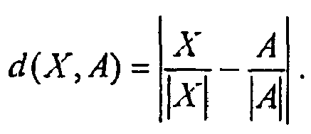

In einem ersten Beispiel kann als Abstand d(X,A) der Vektoren X und A der Winkel zwischen durch sie definierten Ursprungsgeraden verwendet werden.In a first example, as the distance d (X, A) of the vectors X and A, the angle between the lines of origin defined by them can be used.
In einem zweiten Beispiel kann als Abstand d(X,A) der Vektoren X und A folgender Ausdruck verwendet werden: ![]()
![]()
In einem weiteren Beispiel kann als Abstand d(X,A) der Vektoren X und A folgender Ausdruck verwendet werden: ![]()
![]()
In einem weiteren Beispiel kann als Abstand d(X,A) der Vektoren X und A der Ausdruck 
Zum vorstehend detailliert beschriebenen Ausführungsbeispiel sind zahlreiche Weiterbildungen und Alternativen denkbar.Numerous developments and alternatives are conceivable for the exemplary embodiment described above in detail.
Obwohl beispielsweise der Fall von nur zwei möglichen Echtheitsmerkmalen beschrieben und in den Figuren dargestellt wurde, ist selbstverständlich auch eine Verallgemeinerung auf mehr als zwei Echtheitsmerkmale möglich. Ebenso ist selbstverständlich eine Verallgemeinerung auf Meß- und Referenzvektoren X, A1, ..., Ak, möglich, die mehr als n= 2 Komponenten, d. h. mehr als zwei spektrale Meßwerte pro Banknote 3 aufweisen.For example, although the case of only two possible authentication features has been described and illustrated in the figures, it will be understood that a generalization to more than two authenticity features is possible. Likewise, of course, a generalization to measurement and reference vectors X, A 1 , ..., A k , possible, the more than n = 2 components, ie more than two spectral measurements per
Weiterhin kann auch vorgesehen sein, daß die Lumineszenzstrahlung 10 einer Banknote 3 zu verschiedenen Zeiten gemessen und dies bei der Auswertung berücksichtigt wird. Zum einen kann hierbei festgestellt werden, ob die gemessene Strahlung 10 der geprüften Banknote 3 tatsächlich das für die jeweilige Lumineszenzart zu erwartende Zeitverhalten hat. Bevorzugt werden die Banknoten 3 hierbei zeitlich intermittierend durch die Lichtquelle 5 bestrahlt, um z.B. das Abklingverhalten der Lumineszenzstrahlung 10 zeitlich aufgelöst messen zu können. In diesem Fall kann besonders bevorzugt auch eine zeitabhängige Darstellung der Meßvektoren X und/oder der Referenzvektoren A, B gewählt und die Abstandsbildung zeitabhängig durchgeführt werden.Furthermore, it can also be provided that the luminescence radiation 10 of a
Eine weitere Idee der vorliegenden Erfindung besteht darin, daß die Messung der Lumineszenzstrahlung nur an vorbestimmten Teilbereichen der Banknotenfläche erfolgt, welche in besonders bevorzugter Weise nennwertspezifisch gewählt sind. Dies kann beispielsweise dadurch geschehen, daß die Lichtquelle 5 nur einen oder mehrere spezielle Teilbereiche der Banknote 3 beim Vorbeitransport an einer Prüfeinrichtung 3 beleuchtet, bzw. Informationen über die Lage der jeweils beleuchteten Teilbereiche der Banknote 3 bei der Auswertung in der Auswertungseinrichtung 7 berücksichtigt. Diese ortsabhängige Messung der Lumineszenzstrahlung 10 kann beispielsweise dazu verwendet werden, um auch räumlich codierte Echtheitsmerkrnale, die im Banknotenpapier nicht homogen eingebracht sind, unterscheiden zu können.A further idea of the present invention is that the measurement of the luminescence radiation takes place only at predetermined subregions of the banknote surface, which are chosen to be nominal value-specific in a particularly preferred manner. This can be done, for example, by illuminating the
Des weiteren muß die Lumineszenzstrahlung 10 auch nicht zwingend in Reflexion, sondern sie kann alternativ oder zusätzlich auch in Transmission gemessen und ausgewertet werden.Furthermore, the luminescence radiation 10 also does not necessarily have to be measured in reflection, but alternatively or additionally, it can also be measured and evaluated in transmission.
Wie erwähnt wurde, kann es bei der Auswertung störend sein, wenn die Meßsignale ein Hintergrundsignal aufweisen, welches nicht von der Lumineszenzstrahlung herrührt und die Lumineszenzstrahlung 10 überlagert. Diese störenden Hintergrundsignal verfälschen bei der Normierung die Verhältnisse der einzelnen Meßvektoren zu den Referenzvektoren.As has been mentioned, it can be disturbing in the evaluation if the measurement signals have a background signal which does not originate from the luminescence radiation and which superimposes the luminescence radiation 10. This disturbing background signal falsify the ratios of the individual measuring vectors to the reference vectors during normalization.
Zur Veranschaulichung der Problematik ist in der Figur 4 in schematischer Weise mit der durchgezogen gezeichneten Linie L1 der durch den Spektralsensor 6 gemessene spektrale Verlauf der Meßsignale einer beleuchteten Banknote 3, d.h. die Abhängigkeit der Meßsignalintensität I (f) von der Meßsignalfrequenz f dargestellt. Der tatsächlich nur von der Lumineszenzstrahlung 10 stammende Anteil der Meßkurve L1, entsprechend der gestrichelt gezeichneten Kurve L2, ist allerdings vom Betrag her niedriger und durch ein störendes Hintergrundsignal überlagert, welches nicht auf die Lumineszenzstrahlung 10 zurückgeht.To illustrate the problem is shown in Figure 4 in a schematic manner with the solid line L1 drawn by the
Um dieses Hintergrundsignal herauszurechnen, kann zum einen eine Referenzmessung in einer Banknotenlücke durchgeführt werden. Es werden dabei gerade dann mittels des Spektralsensors 6 Meßwerte aufgenommen, wenn sich keine Banknote 3 im Erfassungsbereich des Spektralsensors 6 befindet. Die so gewonnen Signale stellen dann ein Maß für die Stärke des Hintergrundsignals dar und können bei der nachfolgenden Bildung oder Auswertung der Meßvektoren berücksichtigt, z.B. von den Meßwerten bei der Messung der nachfolgenden Banknote 3 abgezogen werden.In order to calculate this background signal, on the one hand, a reference measurement in a banknote gap can be carried out. In this case, measured values are recorded by means of the
Es gibt allerdings Spektralsensoren 6, bei denen die Meßverhältnisse bei der Messung mit Banknote 3 im Vergleich zur Messung ohne Banknote 3 so deutlich unterschieden sind, daß die beim Fall ohne Banknote gemessenen Hintergrundsignale nicht repräsentativ für die mit Banknote gemessenen Hintergrundsignale sind.However, there are
Alternativ kann deswegen z.B. die Größe eines relativen, vorzugsweise des absoluten Minimums und/oder Maximums der Meßsignale in einem zur weiteren Auswertung benutzen Spektralbereich bestimmt werden. Dies kann z.B. eine Stelle im Spektrum sein, an der die zu prüfenden lumineszierenden Substanzen üblicheriveise nicht emittieren. Im Spektrum der Figur 4 befindet sich dieses Minimum exemplarisch bei der Frequenz fMin1 und hat eine Intensität IMin1. Indem nun zumindest vom nachfolgend weiter auszuwertenden Anteil des Spektrums dieser minimale Intensitätswert IMin1 abgezogen wird, d.h. für den betrachteten Spektralbereich die Differenz I(f) - IMin1 gebildet wird, erhält man ein effektives Meßsignal, welches im wesentlichen nur noch auf die Luminezenzstrahlung 10, entsprechend der Kurve L2 zurückgeht und bei der die Hintergrundsignale im wesentlichen abgezogen sind.Alternatively, for example, the size of a relative, preferably the absolute minimum and / or maximum of the measurement signals can be determined in a spectral range used for further evaluation. This may be, for example, a point in the spectrum at which the luminescent substances to be tested do not usually emit. In the spectrum of FIG. 4, this minimum is exemplarily at the frequency f Min1 and has an intensity I Min1 . By subtracting at least from the portion of the spectrum to be further evaluated, this minimum intensity value I Min1 , ie, the difference I (f) - I Min1 is formed for the spectral range under consideration, an effective measurement signal is obtained, which essentially only affects the luminescence radiation 10 , decreases according to the curve L2 and in which the background signals are substantially subtracted.
Eine weitere Variante ist folgende: Da die nachzuweisenden luminesziexenden Substanzen eine vorbekannte Spektralkurve haben, so hat das Verhältnis der Intensität der Lumineszenzstrahlung bei zwei unterschiedlichen Frequenzen einen konstanten vorbekannten Wert. Die beiden Frequenzen können vorzugsweise so gewählt sein, daß sie einem Maximum und einem Minimum der Spektralkurve entsprechen. Beim Fall der Figur 4 sei z.B. das Intensitätsverhältnis I(fMax)/I(fMin2) der Lumineszenzstrahlung 10, entsprechend Kurve L2, gleich einem konstanten Wert ko. Die tatsächlich bei der Prüfung der Banknote 3 gewonnene Meßkurve L1 weist allerdings ein Intensitätsverhältnis I(fMax)/I(fMin2) = IMax/IMin2 auf, das geringer ist als dieser Wert ko. Dieser Unterschied ist gerade durch die Hintergrundsignale bewirkt, die das Lumineszenzspektrum L2 überlagernden.A further variant is the following: Since the luminescent substances to be detected have a previously known spectral curve, the ratio of the intensity of the luminescence radiation at two different frequencies has a constant, known value. The two frequencies may preferably be selected to correspond to a maximum and a minimum of the spectral curve. In the case of FIG. 4, for example, let the intensity ratio I (f max ) / I (f Min 2 ) of the luminescence radiation 10, corresponding to curve L 2 , be equal to a constant value ko. However, the actual measured in the examination of the
Es wird nun berechnet, um welches Maß I0 die Intensität des gesamten Spektrums I(f) gesenkt werden muß, damit das Intensitätsverhältnis I(fMax)/I(fMin2) wiederum dem für die zu erwartende Lumineszenzstrahlung 10 typischen Wert k0 entspricht. Durch Abzug dieses Werts I0 vom gesamten betrachteten Spektralbereich der Kurve L2 erhält man wiederum ein effektives Meßsignal, welches im wesentlichen nur noch auf die Luminezenzstrahlung 10, entsprechend der Kurve L2 zurückgeht, und bei der die Hintergrundsignale im wesentlichen abgezogen sind.It is now calculated by which measure I 0 the intensity of the entire spectrum I (f) must be lowered, so that the intensity ratio I (f max ) / I (f Min2 ) again corresponds to the value k 0 typical for the expected luminescence radiation 10. By subtracting this value I 0 from the entire spectral range of the curve L2 considered, one obtains again an effective measuring signal, which essentially only goes back to the luminescent radiation 10, corresponding to the curve L2, and in which the background signals are essentially subtracted.
Es sei betont, daß anstelle eines linearen Offsets, d.h. eines Abzugs eines konstanten Werts IMin1 bzw. I0 von der Meßintensität I(f) der Meßkurve L2, auch ein anderer, nichtlinearer Offset abgezogen werden kann, bei dem der abgezogenen Wert mit der Frequenz f variiert. D.h., der Betrag kann von Meßwert zu Meßwert des Meßvektors verschieden sein, d.h. es kann auch ein durch das Hintergrundsignal erzeugter Hintergrundvektor verwendet werden. Dies macht dann Sinn, wenn auch die Hintergrundsignale einen nicht-linearen Verlauf, d.h. einen über alle Frequenzen f nicht konstanten Betrag haben. Ist das Emissionsspektrum des Hintergrundsignals bekannt, so kann durch Messung des Hintergrundsignals bei einer einzigen oder mehreren Frequenzen der Hintergrundvektor berechnet werden. Ist der Hintergrundvektor bekannt, so kann er z.B. im Sensor gespeichert und auch ohne Messung von den Meßwerten abgezogen werden.It should be emphasized that, instead of a linear offset, that is to say a deduction of a constant value I Min1 or I 0 from the measurement intensity I (f) of the measurement curve L2, another nonlinear offset can also be subtracted, in which the subtracted value coincides with the reference value Frequency f varies. That is, the amount may be different from measured value to measured value of the measuring vector, ie a background vector generated by the background signal may also be used. This makes sense, even if the background signals have a non-linear course, ie an amount that is not constant over all frequencies f. If the emission spectrum of the background signal is known, the background vector can be calculated by measuring the background signal at a single or multiple frequencies. If the background vector is known, it can for example be stored in the sensor and also be subtracted from the measured values without measurement.
Zudem können die genannten Verfahren zur Kompensation der Hintergrundsignale auch unabhängig vom Gegenstand der Hauptansprüche auch bei anderen Lumineszenzauswerteverfahren mit Vorteil eingesetzt werden.In addition, the said methods for compensating the background signals can also be used advantageously in other luminescence evaluation methods, independently of the subject matter of the main claims.
Die erfindungsgemäße Vorgehensweise ermöglicht folglich eine einfache und sichere Prüfung und Unterscheidung von Echtheitsmerkmalen, insbesondere mit sehr ähnlichem Spektralverlauf, die in Wertdokumenten enthalten sein können.The procedure according to the invention thus makes possible a simple and reliable testing and differentiation of authenticity features, in particular with a very similar spectral profile, which can be contained in value documents.
Claims (15)
- A method for checking value documents (3) having an authenticity feature in the form of at least one luminescent substance, the value document (3) being irradiated with light (9) and the luminescence radiation (10) emanating from the value document (3) detected with spectral resolution to determine whether the authenticity feature is present in the value document (3),
characterized in that
a measuring vector (X) is formed from the measuring values corresponding to different frequencies and/or frequency domains of the luminescence radiation (10), and an object allocation of the measuring vector (X) to one of a plurality of given reference vectors (A 1, ..., A k ) corresponding to different authenticity features is done by allocating at least one object allocation area (G 1, ..., G l ) to each reference vector (A 1, ..., A k ), and checking which object allocation area (G 1, ..., G l ) the measuring vector (X) is located in. - A method according to claim 1, characterized in that the checking method has a further step for checking whether the amount (|X|) of the measuring vector (X) is greater than a given reference value (R).
- A method according to claim 2, characterized in that the step of checking whether the amount (|X|) of the measuring vector (X) is greater than a given reference value (R) is carried out before the step of allocating the measuring vector (X) to one of a plurality of given reference vectors (A 1, ..., A k ).
- A method according to at least one of the previous claims, characterized in that the measuring vector (X) and the reference vectors (A 1 , ..., A k ) are normalized.
- A method according to at least one of the previous claims, characterized in that the object allocation of the measuring vector (X) to one of the reference vectors (A m ) is done by comparing the measuring vector (X) with a plurality of reference vectors (A1, ..., A k ) and/or with at least one quantity (T) which depends on at least two reference vectors (A 1, ..., A k ).
- A method according to at least one of the previous claims, characterized in that the object allocation of the measuring vector (X) to one of the reference vectors (A m ) is done by determining the smallest difference, e.g. the smallest distance (d(X,A m )) from the measuring vector (X) to the reference vectors (A 1 , ..., A k ).
- A method according to at least one of the previous claims, characterized in that the quantity (7) which depends on at least two reference vectors (A, B) is formed as a separation plane (T) between the two reference vectors (A, B), such as an (n-1) dimensional hyperplane (T) between the two n-dimensional reference vectors (A, B), the separation plane (T) separating the object allocation areas (G A , G B ) of the two reference vectors (A, B) from each other.
- A method according to at least one of the previous claims, characterized in that the object allocation of the measuring vector (X) to one of the reference vectors (A m ) is determined by determining the position of the measuring vector (X) relative to the separation plane (7).
- A method according to at least one of the previous claims, characterized in that the luminescence radiation (10) is measured with time resolution on a value document (3) to be checked, whereby the comparison of measuring vector (X) and reference vectors (A, B) can be done time-dependently.
- A method according to at least one of the previous claims, characterized in that the measurement of the luminescence radiation (10) is done only on one or more predetermined partial areas of the value document surface which can be predetermined denomination-specifically.
- A method according to at least one of the previous claims, characterized in that the measuring vector (X) comprises measuring values of the infrared or ultraviolet, i.e. an invisible, spectral range.
- A method according to at least one of the previous claims, characterized in that the evaluation of the measuring values takes account of a background signal (L2-L1) which does not come from the luminescence radiation (10).
- A method according to claim 13, characterized in that, for forming the measuring vector, an amount depending on the magnitude of the background signal (L2-L1) is subtracted from the measuring values.
- A method according to claim 14, characterized in that the amount is dependent on the magnitude of a minimum and/or maximum of the measuring values and/or a ratio of two measuring values.
- An apparatus (1) for checking value documents (3) having an authenticity feature in the form of at least one luminescent substance, having a light source (5) for irradiating the value document (3) and a spectral sensor (6) for detecting with spectral resolution the luminescence radiation (10) emanating from the value document (3), and having an evaluation device (7) connected to the spectral sensor (6) for determining whether the authenticity feature is present in the value document (3),
characterized in that
the evaluation device (7) is designed so that a measuring vector (X) is formed from the measuring values corresponding to different frequencies and/or frequency domains of the luminescence radiation (10), and an object allocation of the measuring vector (X) to one of a plurality of given reference vectors (A 1, ..., A k ) corresponding to different authenticity features is done by allocating at least one object allocation area (G 1, ..., G l ) to each reference vector (A 1, ..., A k) and checking which object allocation area the measuring vector (X) is located in.
Applications Claiming Priority (3)
| Application Number | Priority Date | Filing Date | Title |
|---|---|---|---|
| DE10256114 | 2002-11-29 | ||
| DE10256114A DE10256114A1 (en) | 2002-11-29 | 2002-11-29 | Method and device for checking documents of value |
| PCT/EP2003/013435 WO2004051582A2 (en) | 2002-11-29 | 2003-11-28 | Method and device for verifying valuable documents |
Publications (2)
| Publication Number | Publication Date |
|---|---|
| EP1567991A2 EP1567991A2 (en) | 2005-08-31 |
| EP1567991B1 true EP1567991B1 (en) | 2006-04-19 |
Family
ID=32308893
Family Applications (1)
| Application Number | Title | Priority Date | Filing Date |
|---|---|---|---|
| EP03767703A Expired - Lifetime EP1567991B1 (en) | 2002-11-29 | 2003-11-28 | Method and device for verifying valuable documents |
Country Status (7)
| Country | Link |
|---|---|
| US (1) | US7873199B2 (en) |
| EP (1) | EP1567991B1 (en) |
| AT (1) | ATE323920T1 (en) |
| AU (1) | AU2003292157A1 (en) |
| DE (2) | DE10256114A1 (en) |
| ES (1) | ES2259149T3 (en) |
| WO (1) | WO2004051582A2 (en) |
Families Citing this family (3)
| Publication number | Priority date | Publication date | Assignee | Title |
|---|---|---|---|---|
| DE10346636A1 (en) | 2003-10-08 | 2005-05-12 | Giesecke & Devrient Gmbh | Device and method for checking value documents |
| US8330122B2 (en) * | 2007-11-30 | 2012-12-11 | Honeywell International Inc | Authenticatable mark, systems for preparing and authenticating the mark |
| DE102011016509A1 (en) | 2011-04-08 | 2012-10-11 | Giesecke & Devrient Gmbh | Method for checking value documents |
Family Cites Families (11)
| Publication number | Priority date | Publication date | Assignee | Title |
|---|---|---|---|---|
| AT330574B (en) | 1972-05-03 | 1976-07-12 | Int Security Systems Sa | COUNTERFEIT SECURITY SECURITIES |
| JPS5532132A (en) * | 1978-08-28 | 1980-03-06 | Laurel Bank Machine Co | Bill discriminator |
| JPS5665291A (en) * | 1979-10-31 | 1981-06-02 | Tokyo Shibaura Electric Co | Discriminator for printed matter |
| US4464786A (en) * | 1981-06-17 | 1984-08-07 | Tokyo Shibaura Denki Kabushiki Kaisha | System for identifying currency note |
| NL8202920A (en) | 1982-07-20 | 1984-02-16 | Tno | APPARATUS FOR RECOGNIZING AND EXAMINING LEAF ARTICLES SUCH AS BANKNOTES OR THE LIKE. |
| CH684856A5 (en) * | 1992-11-30 | 1995-01-13 | Mars Inc | Method for classifying a pattern - in particular a pattern of a bill or a coin - and means for implementing the method. |
| GB2284293B (en) * | 1993-11-30 | 1998-06-03 | Mars Inc | Article classifying method and apparatus |
| JP3366438B2 (en) * | 1994-05-25 | 2003-01-14 | 東洋通信機株式会社 | Paper type identification method |
| US5757001A (en) * | 1996-05-01 | 1998-05-26 | The Regents Of The University Of Calif. | Detection of counterfeit currency |
| DE60117930T2 (en) * | 2000-06-06 | 2006-10-05 | Agilent Technologies Inc., A Delaware Corp., Palo Alto | Method and system for the automatic extraction of data from a molecular array |
| DE10113268B4 (en) | 2001-03-16 | 2021-06-24 | Bundesdruckerei Gmbh | Sensor for the authentication of security features on value and / or security documents |
-
2002
- 2002-11-29 DE DE10256114A patent/DE10256114A1/en not_active Withdrawn
-
2003
- 2003-11-28 US US10/535,409 patent/US7873199B2/en active Active
- 2003-11-28 ES ES03767703T patent/ES2259149T3/en not_active Expired - Lifetime
- 2003-11-28 AU AU2003292157A patent/AU2003292157A1/en not_active Abandoned
- 2003-11-28 AT AT03767703T patent/ATE323920T1/en active
- 2003-11-28 EP EP03767703A patent/EP1567991B1/en not_active Expired - Lifetime
- 2003-11-28 WO PCT/EP2003/013435 patent/WO2004051582A2/en not_active Application Discontinuation
- 2003-11-28 DE DE50303063T patent/DE50303063D1/en not_active Expired - Lifetime
Also Published As
| Publication number | Publication date |
|---|---|
| AU2003292157A8 (en) | 2004-06-23 |
| ES2259149T3 (en) | 2006-09-16 |
| EP1567991A2 (en) | 2005-08-31 |
| US7873199B2 (en) | 2011-01-18 |
| WO2004051582A2 (en) | 2004-06-17 |
| US20060153437A1 (en) | 2006-07-13 |
| DE50303063D1 (en) | 2006-05-24 |
| ATE323920T1 (en) | 2006-05-15 |
| DE10256114A1 (en) | 2004-06-09 |
| WO2004051582A3 (en) | 2004-08-26 |
| AU2003292157A1 (en) | 2004-06-23 |
Similar Documents
| Publication | Publication Date | Title |
|---|---|---|
| DE2824849C2 (en) | Method and device for determining the condition and / or the authenticity of sheet material | |
| EP2577620B1 (en) | Device for testing the authenticity of valuable documents | |
| DE2320731A1 (en) | FALSE-PROOF SECURITIES AND DEVICE FOR VERIFICATION OF SUCH SECURITIES | |
| DE102007019107A1 (en) | Method and device for checking value documents | |
| EP1112555B1 (en) | Method and device for controlling the state of securities using a dark-field and a bright-field measurement. | |
| EP3108461B1 (en) | Method for examining a value document, and means for carrying out the method | |
| EP2936455B1 (en) | Sensor and method for verifying value documents | |
| DE2924605C2 (en) | Process for the optical differentiation of test objects | |
| EP3443542B1 (en) | Device and method for checking value documents, in particular banknotes, and value document processing system | |
| EP3400584B1 (en) | Completeness check of a value document | |
| EP1567991B1 (en) | Method and device for verifying valuable documents | |
| EP2997553B1 (en) | Device and method for examining value documents, in particular banknotes, and value document processing system | |
| EP3210195B1 (en) | Device and method for testing valuable documents and system for handling of valuable documents | |
| DE102012022216A1 (en) | Device and method for checking value documents | |
| EP3134878B1 (en) | Method of checking a value document | |
| EP2695146A1 (en) | Method for checking valuable documents | |
| WO2024012634A1 (en) | Sensor and method for checking valuable documents having at least one reflective security element | |
| WO2014029476A1 (en) | Method and apparatus for checking valuable documents | |
| DE102020004471A1 (en) | Method and sensor for checking documents of value | |
| DE102020002587A1 (en) | Method and device for testing a substrate with a luminescent substance | |
| DE10233052A1 (en) | Multiple document pull-off detection system for a document, especially banknote or check, processing system, whereby the documents are illuminated in their most sensitive areas and the transmitted radiation measured |
Legal Events
| Date | Code | Title | Description |
|---|---|---|---|
| PUAI | Public reference made under article 153(3) epc to a published international application that has entered the european phase |
Free format text: ORIGINAL CODE: 0009012 |
|
| 17P | Request for examination filed |
Effective date: 20050629 |
|
| AK | Designated contracting states |
Kind code of ref document: A2 Designated state(s): AT BE BG CH CY CZ DE DK EE ES FI FR GB GR HU IE IT LI LU MC NL PT RO SE SI SK TR |
|
| AX | Request for extension of the european patent |
Extension state: AL LT LV MK |
|
| GRAP | Despatch of communication of intention to grant a patent |
Free format text: ORIGINAL CODE: EPIDOSNIGR1 |
|
| GRAS | Grant fee paid |
Free format text: ORIGINAL CODE: EPIDOSNIGR3 |
|
| GRAA | (expected) grant |
Free format text: ORIGINAL CODE: 0009210 |
|
| DAX | Request for extension of the european patent (deleted) | ||
| AK | Designated contracting states |
Kind code of ref document: B1 Designated state(s): AT BE BG CH CY CZ DE DK EE ES FI FR GB GR HU IE IT LI LU MC NL PT RO SE SI SK TR |
|
| PG25 | Lapsed in a contracting state [announced via postgrant information from national office to epo] |
Ref country code: IT Free format text: LAPSE BECAUSE OF FAILURE TO SUBMIT A TRANSLATION OF THE DESCRIPTION OR TO PAY THE FEE WITHIN THE PRESCRIBED TIME-LIMIT;WARNING: LAPSES OF ITALIAN PATENTS WITH EFFECTIVE DATE BEFORE 2007 MAY HAVE OCCURRED AT ANY TIME BEFORE 2007. THE CORRECT EFFECTIVE DATE MAY BE DIFFERENT FROM THE ONE RECORDED. Effective date: 20060419 Ref country code: SI Free format text: LAPSE BECAUSE OF FAILURE TO SUBMIT A TRANSLATION OF THE DESCRIPTION OR TO PAY THE FEE WITHIN THE PRESCRIBED TIME-LIMIT Effective date: 20060419 Ref country code: IE Free format text: LAPSE BECAUSE OF FAILURE TO SUBMIT A TRANSLATION OF THE DESCRIPTION OR TO PAY THE FEE WITHIN THE PRESCRIBED TIME-LIMIT Effective date: 20060419 Ref country code: RO Free format text: LAPSE BECAUSE OF FAILURE TO SUBMIT A TRANSLATION OF THE DESCRIPTION OR TO PAY THE FEE WITHIN THE PRESCRIBED TIME-LIMIT Effective date: 20060419 Ref country code: NL Free format text: LAPSE BECAUSE OF FAILURE TO SUBMIT A TRANSLATION OF THE DESCRIPTION OR TO PAY THE FEE WITHIN THE PRESCRIBED TIME-LIMIT Effective date: 20060419 Ref country code: CZ Free format text: LAPSE BECAUSE OF FAILURE TO SUBMIT A TRANSLATION OF THE DESCRIPTION OR TO PAY THE FEE WITHIN THE PRESCRIBED TIME-LIMIT Effective date: 20060419 Ref country code: FI Free format text: LAPSE BECAUSE OF FAILURE TO SUBMIT A TRANSLATION OF THE DESCRIPTION OR TO PAY THE FEE WITHIN THE PRESCRIBED TIME-LIMIT Effective date: 20060419 Ref country code: SK Free format text: LAPSE BECAUSE OF FAILURE TO SUBMIT A TRANSLATION OF THE DESCRIPTION OR TO PAY THE FEE WITHIN THE PRESCRIBED TIME-LIMIT Effective date: 20060419 |
|
| REG | Reference to a national code |
Ref country code: GB Ref legal event code: FG4D Free format text: NOT ENGLISH |
|
| REG | Reference to a national code |
Ref country code: CH Ref legal event code: NV Representative=s name: PATENTANWAELTE SCHAAD, BALASS, MENZL & PARTNER AG |
|
| GBT | Gb: translation of ep patent filed (gb section 77(6)(a)/1977) |
Effective date: 20060503 |
|
| REF | Corresponds to: |
Ref document number: 50303063 Country of ref document: DE Date of ref document: 20060524 Kind code of ref document: P |
|
| REG | Reference to a national code |
Ref country code: IE Ref legal event code: FG4D Free format text: LANGUAGE OF EP DOCUMENT: GERMAN |
|
| PG25 | Lapsed in a contracting state [announced via postgrant information from national office to epo] |
Ref country code: SE Free format text: LAPSE BECAUSE OF FAILURE TO SUBMIT A TRANSLATION OF THE DESCRIPTION OR TO PAY THE FEE WITHIN THE PRESCRIBED TIME-LIMIT Effective date: 20060719 Ref country code: DK Free format text: LAPSE BECAUSE OF FAILURE TO SUBMIT A TRANSLATION OF THE DESCRIPTION OR TO PAY THE FEE WITHIN THE PRESCRIBED TIME-LIMIT Effective date: 20060719 |
|
| REG | Reference to a national code |
Ref country code: ES Ref legal event code: FG2A Ref document number: 2259149 Country of ref document: ES Kind code of ref document: T3 |
|
| PG25 | Lapsed in a contracting state [announced via postgrant information from national office to epo] |
Ref country code: PT Free format text: LAPSE BECAUSE OF FAILURE TO SUBMIT A TRANSLATION OF THE DESCRIPTION OR TO PAY THE FEE WITHIN THE PRESCRIBED TIME-LIMIT Effective date: 20060919 |
|
| ET | Fr: translation filed | ||
| NLV1 | Nl: lapsed or annulled due to failure to fulfill the requirements of art. 29p and 29m of the patents act | ||
| REG | Reference to a national code |
Ref country code: IE Ref legal event code: FD4D |
|
| PG25 | Lapsed in a contracting state [announced via postgrant information from national office to epo] |
Ref country code: MC Free format text: LAPSE BECAUSE OF NON-PAYMENT OF DUE FEES Effective date: 20061130 Ref country code: BE Free format text: LAPSE BECAUSE OF NON-PAYMENT OF DUE FEES Effective date: 20061130 |
|
| PLAX | Notice of opposition and request to file observation + time limit sent |
Free format text: ORIGINAL CODE: EPIDOSNOBS2 |
|
| PLBI | Opposition filed |
Free format text: ORIGINAL CODE: 0009260 |
|
| 26 | Opposition filed |
Opponent name: BUNDESDRUCKEREI GMBH Effective date: 20070117 |
|
| PLAF | Information modified related to communication of a notice of opposition and request to file observations + time limit |
Free format text: ORIGINAL CODE: EPIDOSCOBS2 |
|
| PLBB | Reply of patent proprietor to notice(s) of opposition received |
Free format text: ORIGINAL CODE: EPIDOSNOBS3 |
|
| BERE | Be: lapsed |
Owner name: GIESECKE & DEVRIENT G.M.B.H. Effective date: 20061130 |
|
| PG25 | Lapsed in a contracting state [announced via postgrant information from national office to epo] |
Ref country code: GR Free format text: LAPSE BECAUSE OF FAILURE TO SUBMIT A TRANSLATION OF THE DESCRIPTION OR TO PAY THE FEE WITHIN THE PRESCRIBED TIME-LIMIT Effective date: 20060720 |
|
| PG25 | Lapsed in a contracting state [announced via postgrant information from national office to epo] |
Ref country code: EE Free format text: LAPSE BECAUSE OF FAILURE TO SUBMIT A TRANSLATION OF THE DESCRIPTION OR TO PAY THE FEE WITHIN THE PRESCRIBED TIME-LIMIT Effective date: 20060419 Ref country code: BG Free format text: LAPSE BECAUSE OF FAILURE TO SUBMIT A TRANSLATION OF THE DESCRIPTION OR TO PAY THE FEE WITHIN THE PRESCRIBED TIME-LIMIT Effective date: 20060719 |
|
| PG25 | Lapsed in a contracting state [announced via postgrant information from national office to epo] |
Ref country code: TR Free format text: LAPSE BECAUSE OF FAILURE TO SUBMIT A TRANSLATION OF THE DESCRIPTION OR TO PAY THE FEE WITHIN THE PRESCRIBED TIME-LIMIT Effective date: 20060419 Ref country code: LU Free format text: LAPSE BECAUSE OF NON-PAYMENT OF DUE FEES Effective date: 20061128 Ref country code: HU Free format text: LAPSE BECAUSE OF FAILURE TO SUBMIT A TRANSLATION OF THE DESCRIPTION OR TO PAY THE FEE WITHIN THE PRESCRIBED TIME-LIMIT Effective date: 20061020 |
|
| PG25 | Lapsed in a contracting state [announced via postgrant information from national office to epo] |
Ref country code: CY Free format text: LAPSE BECAUSE OF FAILURE TO SUBMIT A TRANSLATION OF THE DESCRIPTION OR TO PAY THE FEE WITHIN THE PRESCRIBED TIME-LIMIT Effective date: 20060419 |
|
| PLCK | Communication despatched that opposition was rejected |
Free format text: ORIGINAL CODE: EPIDOSNREJ1 |
|
| PLBN | Opposition rejected |
Free format text: ORIGINAL CODE: 0009273 |
|
| STAA | Information on the status of an ep patent application or granted ep patent |
Free format text: STATUS: OPPOSITION REJECTED |
|
| 27O | Opposition rejected |
Effective date: 20100929 |
|
| REG | Reference to a national code |
Ref country code: DE Ref legal event code: R082 Ref document number: 50303063 Country of ref document: DE |
|
| REG | Reference to a national code |
Ref country code: FR Ref legal event code: PLFP Year of fee payment: 13 |
|
| REG | Reference to a national code |
Ref country code: FR Ref legal event code: PLFP Year of fee payment: 14 |
|
| REG | Reference to a national code |
Ref country code: DE Ref legal event code: R081 Ref document number: 50303063 Country of ref document: DE Owner name: GIESECKE+DEVRIENT CURRENCY TECHNOLOGY GMBH, DE Free format text: FORMER OWNER: GIESECKE & DEVRIENT GMBH, 81677 MUENCHEN, DE |
|
| REG | Reference to a national code |
Ref country code: FR Ref legal event code: PLFP Year of fee payment: 15 |
|
| REG | Reference to a national code |
Ref country code: CH Ref legal event code: PUE Owner name: GIESECKE+DEVRIENT CURRENCY TECHNOLOGY GMBH, DE Free format text: FORMER OWNER: GIESECKE AND DEVRIENT GMBH, DE |
|
| REG | Reference to a national code |
Ref country code: ES Ref legal event code: PC2A Owner name: GIESECKE+DEVRIENT CURRENCY TECHNOLOGY GMBH Effective date: 20180123 |
|
| REG | Reference to a national code |
Ref country code: GB Ref legal event code: 732E Free format text: REGISTERED BETWEEN 20180118 AND 20180124 |
|
| REG | Reference to a national code |
Ref country code: AT Ref legal event code: PC Ref document number: 323920 Country of ref document: AT Kind code of ref document: T Owner name: GIESECKE+DEVRIENT CURRENCY TECHNOLOGY GMBH, DE Effective date: 20180425 |
|
| REG | Reference to a national code |
Ref country code: FR Ref legal event code: TP Owner name: GIESECKE+DEVRIENT CURRENCY TECHNOLOGY GMBH, DE Effective date: 20180530 |
|
| PGFP | Annual fee paid to national office [announced via postgrant information from national office to epo] |
Ref country code: GB Payment date: 20221123 Year of fee payment: 20 Ref country code: FR Payment date: 20221121 Year of fee payment: 20 Ref country code: ES Payment date: 20221216 Year of fee payment: 20 Ref country code: DE Payment date: 20221130 Year of fee payment: 20 Ref country code: AT Payment date: 20221117 Year of fee payment: 20 |
|
| PGFP | Annual fee paid to national office [announced via postgrant information from national office to epo] |
Ref country code: CH Payment date: 20221124 Year of fee payment: 20 |
|
| P01 | Opt-out of the competence of the unified patent court (upc) registered |
Effective date: 20230520 |
|
| REG | Reference to a national code |
Ref country code: DE Ref legal event code: R071 Ref document number: 50303063 Country of ref document: DE |
|
| REG | Reference to a national code |
Ref country code: CH Ref legal event code: PL |
|
| REG | Reference to a national code |
Ref country code: ES Ref legal event code: FD2A Effective date: 20231205 |
|
| REG | Reference to a national code |
Ref country code: GB Ref legal event code: PE20 Expiry date: 20231127 |
|
| REG | Reference to a national code |
Ref country code: AT Ref legal event code: MK07 Ref document number: 323920 Country of ref document: AT Kind code of ref document: T Effective date: 20231128 |
|
| PG25 | Lapsed in a contracting state [announced via postgrant information from national office to epo] |
Ref country code: GB Free format text: LAPSE BECAUSE OF EXPIRATION OF PROTECTION Effective date: 20231127 |
|
| PG25 | Lapsed in a contracting state [announced via postgrant information from national office to epo] |
Ref country code: ES Free format text: LAPSE BECAUSE OF EXPIRATION OF PROTECTION Effective date: 20231129 |
|
| PG25 | Lapsed in a contracting state [announced via postgrant information from national office to epo] |
Ref country code: GB Free format text: LAPSE BECAUSE OF EXPIRATION OF PROTECTION Effective date: 20231127 Ref country code: ES Free format text: LAPSE BECAUSE OF EXPIRATION OF PROTECTION Effective date: 20231129 |