EP1567924B1 - Zylindrischer gerätezyklenzähler - Google Patents
Zylindrischer gerätezyklenzähler Download PDFInfo
- Publication number
- EP1567924B1 EP1567924B1 EP03812467A EP03812467A EP1567924B1 EP 1567924 B1 EP1567924 B1 EP 1567924B1 EP 03812467 A EP03812467 A EP 03812467A EP 03812467 A EP03812467 A EP 03812467A EP 1567924 B1 EP1567924 B1 EP 1567924B1
- Authority
- EP
- European Patent Office
- Prior art keywords
- tool
- counter
- cycle
- substantially cylindrical
- actuator
- Prior art date
- Legal status (The legal status is an assumption and is not a legal conclusion. Google has not performed a legal analysis and makes no representation as to the accuracy of the status listed.)
- Expired - Lifetime
Links
- 238000000034 method Methods 0.000 claims abstract description 22
- 238000004519 manufacturing process Methods 0.000 claims abstract description 20
- 230000004044 response Effects 0.000 claims abstract description 4
- 238000009434 installation Methods 0.000 claims description 13
- 238000004891 communication Methods 0.000 claims description 5
- 238000012423 maintenance Methods 0.000 description 23
- 230000007246 mechanism Effects 0.000 description 15
- 230000006870 function Effects 0.000 description 7
- 238000003754 machining Methods 0.000 description 7
- 230000000994 depressogenic effect Effects 0.000 description 5
- 230000036961 partial effect Effects 0.000 description 4
- 238000005266 casting Methods 0.000 description 2
- 238000010276 construction Methods 0.000 description 2
- 238000005520 cutting process Methods 0.000 description 2
- 230000000881 depressing effect Effects 0.000 description 2
- 238000013461 design Methods 0.000 description 2
- 230000005294 ferromagnetic effect Effects 0.000 description 2
- 238000002347 injection Methods 0.000 description 2
- 239000007924 injection Substances 0.000 description 2
- 239000000543 intermediate Substances 0.000 description 2
- 238000005461 lubrication Methods 0.000 description 2
- 239000000463 material Substances 0.000 description 2
- 230000003449 preventive effect Effects 0.000 description 2
- 230000008569 process Effects 0.000 description 2
- 230000001681 protective effect Effects 0.000 description 2
- 238000012360 testing method Methods 0.000 description 2
- 230000001154 acute effect Effects 0.000 description 1
- 239000000853 adhesive Substances 0.000 description 1
- 230000001070 adhesive effect Effects 0.000 description 1
- 238000013459 approach Methods 0.000 description 1
- 230000000903 blocking effect Effects 0.000 description 1
- 230000008859 change Effects 0.000 description 1
- 238000010586 diagram Methods 0.000 description 1
- 238000005553 drilling Methods 0.000 description 1
- 238000009429 electrical wiring Methods 0.000 description 1
- 238000005265 energy consumption Methods 0.000 description 1
- 230000005484 gravity Effects 0.000 description 1
- 230000008520 organization Effects 0.000 description 1
- 230000002035 prolonged effect Effects 0.000 description 1
- 230000002829 reductive effect Effects 0.000 description 1
- 230000000717 retained effect Effects 0.000 description 1
- 238000003856 thermoforming Methods 0.000 description 1
- 230000036962 time dependent Effects 0.000 description 1
- XLYOFNOQVPJJNP-UHFFFAOYSA-N water Substances O XLYOFNOQVPJJNP-UHFFFAOYSA-N 0.000 description 1
Images


Classifications
-
- B—PERFORMING OPERATIONS; TRANSPORTING
- B29—WORKING OF PLASTICS; WORKING OF SUBSTANCES IN A PLASTIC STATE IN GENERAL
- B29C—SHAPING OR JOINING OF PLASTICS; SHAPING OF MATERIAL IN A PLASTIC STATE, NOT OTHERWISE PROVIDED FOR; AFTER-TREATMENT OF THE SHAPED PRODUCTS, e.g. REPAIRING
- B29C45/00—Injection moulding, i.e. forcing the required volume of moulding material through a nozzle into a closed mould; Apparatus therefor
- B29C45/17—Component parts, details or accessories; Auxiliary operations
- B29C2045/1784—Component parts, details or accessories not otherwise provided for; Auxiliary operations not otherwise provided for
- B29C2045/1796—Moulds carrying mould related information or codes, e.g. bar codes, counters
Definitions
- a pair of side plates 30 connect the upper tool block 26 to the lower tool plate 28.
- the tool portions 11 and 12 may come in various sizes and shapes that differ from those illustrated herein. More specifically, some tools for parts having complex shapes may be formed of three or more moving tool portions which define the tool cavity when held in a closed position, rather than being defined by a pair of tool halves as illustrated.
- the tool halves 11 and 12 are shown in their conventional orientation when the tools are being constructed by a tool maker or being stored. It is to be understood that, in use when installed in a tool press (not shown), the tool is rotated ninety degrees (90°) so that the tooled part falls from the tool cavity by force of gravity after ejection from the tool cavity.
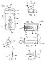
- the first illustrated counter 35 has a substantially cylindrical housing 45 with a block-shaped extension 46, which forms a tough, closed body or housing for substantially enclosing and protecting the internal components, which in this embodiment are shown in FIGS. 7-10 .
- the counter 35 may be mounted in various manners--that is, attached to the tool in various ways.
- a cylindrical bore 48 is machined in the tool block 26 from the side of the mold plate opposite the parting line with the housing 45 being received in the pocket.
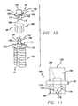
- the housing 45 of the counter 35 has a two-part construction with front half 122 containing the window 85 and a back half 124 joined thereto.
- Each of the halves 122 and 124 have a first end 126 with a bore dimensioned to receive the plunger 36 and a second end 127 with an end wall 131 having a tongue 123 adapted to receive a groove 111 formed on the end cap 109.
- Central orifice 107 of end cap 109 receives the stem 110.
- the grooved rectangular extension 129 of the end cap 109 mates with the tongued rectangular cut-out of the end wall 131 of the window half 122.
- a cylindrical slot 125 (not shown, see FIG.
- the tool is used for just-in-time production
- the date and clock may be used to provide in memory a history of the particular times of usage of the tool.
- the cylindrical counter of the present invention be manufactured in a variety of counter heights which approximately match commonly used plates heights that define a portion of the parting line of the tool.
- the manufacture of counters approximately matching the predetermined heights of the most common plate sidewalls can greatly facilitate installation of the counters.
Landscapes
- Engineering & Computer Science (AREA)
- Manufacturing & Machinery (AREA)
- Mechanical Engineering (AREA)
- Moulds For Moulding Plastics Or The Like (AREA)
- Measurement Of Unknown Time Intervals (AREA)
- Lining Or Joining Of Plastics Or The Like (AREA)
- Presses And Accessory Devices Thereof (AREA)
- Push-Button Switches (AREA)
Claims (14)
- Gerätezyklenzähler für die Installation in einem Fertigungswerkzeug (10) mit beweglichen Hälften (11, 12; 211, 212), die aus einer offenen Position in eine geschlossene Position bewegt werden, um einen geformten Gegenstand zu produzieren, wobei die Bewegung des Werkzeugs von der offenen in die geschlossene Position dabei einen Zyklus bildet, besagter Gerätezyklenzähler umfassend: eine Ziffernanzeige (114, 114A, 477) zum Anzeigen eines Zyklenzählstands; einen Auslöser (36, 120, 320, 436), der in operativer Weise mit der Zählereinheit verbunden ist und durch die Beendigung eines Produktionszyklus ausgelöst wird; eine Zählereinheit (38, 106) für das Aufzeichnen eines Zyklenzählstands in Erwiderung auf das Betätigung des Auslösers, wobei die Zählereinheit operabel verbunden ist mit der Ziffernanzeige, gekennzeichnet durch ein die Zählereinheit einschließendes im Wesentlichen zylindrisches Außengehäuse (45), wobei das im Wesentlichen zylindrische Außengehäuse (45) ein erstes Ende (126), ein zweites Ende (131) und eine sich zwischen dem ersten Ende (126) und dem zweiten Ende (131) erstreckende Seitenwand mit einem gekrümmten Teilbereich umfasst.
- Gerätezyklenzähler nach Anspruch 1, dadurch gekennzeichnet, dass der gekrümmte Teilbereich der Seitenwand einen sich von dort nach außen erstreckenden Überstand aufweist und der Überstand so bemessen ist, zumindest in einen Teil des Fertigungswerkzeugs einzugreifen, um eine Rotation des Zählers um die Längsachse des Zyklenzählers zu verhindern, wenn der Zähler im Fertigungswerkzeug angebracht ist.
- Gerätezyklenzähler nach Anspruch 2, dadurch gekennzeichnet, dass der Überstand ein Paar parallele Wände umfasst, die von dem gekrümmten Teilbereich der Seitenwand des Außengehäuses (45) nach außen ragen und eine im Wesentlichen ebenflächige Seitenwand, die sich zwischen dem Paar paralleler Wände erstreckt.
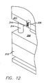
- Gerätezyklenzähler nach Anspruch 3, dadurch gekennzeichnet, dass ein Anzeigefenster (85, 385) in dem im Wesentlichen ebenflächigen Teilbereich des Überstandes positioniert ist und der Überstand und die Anzeige bemessen sind, um in eine in der Außenwand des Fertigungswerkzeugs erstellte Öffnung zu ragen, so dass die Anzeige von außerhalb des Fertigungswerkzeugs (10) sichtbar ist.
- Gerätezyklenzähler nach Anspruch 1, dadurch gekennzeichnet, dass die Distanz zwischen dem ersten Ende (126) und dem zweiten Ende (131) die Höhe der Seitenwand definiert, die Höhe der Seitenwand so gewählt ist, dass sie annähernd mit der vorgegebenen Höhe einer Werkzeugplatte, die einen Teil einer der Werkzeughälften (11, 12; 211, 212) bildet, übereinstimmt und zumindest einen Teil der Werkzeugteilungslinie definiert, welche die Grenze zwischen den zwei Werkzeughälften darstellt.
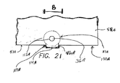
- Gerätezyklenzähler nach Anspruch 5, dadurch gekennzeichnet, dass die Höhe der Seitenwand gewählt wird, um eine vorbestimmte Distanz zu bilden, die geringer ist als die Höhe der Werkzeugplatte, der Auslöser am ersten Ende (126) des Zählers positioniert ist und sich von dem ersten Ende des Gehäuses um eine größere als die vorbestimmte Distanz nach außen erstreckt, so dass sich der Auslöser, wenn der Gerätezyklenzähler in die Werkzeugplatte eingebaut wird, durch eine in der Werkzeugplatte eingebrachte Öffnung über die Teilungslinie des Fertigungswerkzeugs (10) hinaus erstreckt.
- Gerätezyklenzähler nach Anspruch 5, dadurch gekennzeichnet, dass die Höhe der Seitenwand eine vorbestimmte Distanz kleiner als die der Werkzeugplatte ist, der Auslöser am ersten Ende des Zählers positioniert ist und sich von dem ersten Ende des Gehäuses um eine kleinere als die vorbestimmte Distanz nach außen erstreckt, der Auslöser eine gewundene Oberfläche für die Verbindung mit einem gegenüberliegenden Stab mit einer vorbestimmten Länge aufweist, die in Kombination mit der Höhe der Seitenwand länger als die vorbestimmte Distanz ist, so dass sich der Stab durch eine oberhalb der Teilungslinie des Fertigungswerkzeugs (10) in der Platte befindlichen Bohrung erstreckt.
- Gerätezyklenzähler nach Anspruch 1, dadurch gekennzeichnet, dass der Auslöser einen Näherungsschalter umfasst, der gänzlich innerhalb des im Wesentlichen zylindrischen Außengehäuses (45) des Zyklenzählers angebracht ist und dass der Auslöser elektrisch mit der Ziffernanzeige (114, 114A, 477) verbunden ist.
- Gerätezyklenzähler nach Anspruch 1, dadurch gekennzeichnet, dass der Auslöser einen mechanischen Kolben umfasst, der sich durch das im Wesentlichen zylindrische Außengehäuse (45) des Zyklenzählers erstreckt, eine mechanische Anzeige mit dem Kolben verbunden ist, welche einen Zyklenzählstand anzeigt, ohne elektrische Leistung zu verbrauchen, eine elektrische Speichereinheit, welche operativ mit dem Auslöser verbunden ist, um zumindest einen Gerätezyklenzählstand elektronisch zu speichern und einen Ausgabeport, um die gespeicherten Informationen an eine externe Einheit zu übermitteln.
- Verfahren zum Installieren eines im Wesentlichen zylindrischen Gerätezyklenzählers gemäß eines der Ansprüche 1 bis 9 mit einem vorbestimmten Durchmesser in einem Werkzeug mit mindestens einem beweglichen Werkzeugteil zur Verwendung innerhalb eines Presswerkzeugs, folgende Schritte umfassend: Ausbilden einer im Wesentlichen zylindrischen Bohrung in einem Werkzeugteil, die einen Durchmesser aufweist, der größer als der vorbestimmte Durchmesser des im Wesentlichen zylindrischen Geräteszyklenzählers ist; und Anbringen des im Wesentlichen zylindrischen Zyklenzählers innerhalb der in dem Werkzeugteil gebildeten im Wesentlichen zylindrischen Bohrung, wobei der im Wesentlichen zylindrische Gerätezyklenzähler ein Außengehäuse umfasst, welches ein erstes Ende, ein zweites Ende und eine sich zwischen dem ersten Ende und dem zweiten Ende erstreckende Seitenwand mit einem gekrümmten Teilbereich umfasst.
- Verfahren nach Anspruch 10, dadurch gekennzeichnet, dass der im Wesentlichen zylindrische Zyklenzähler eine Zyklenzählanzeige umfasst und ein erster Werkzeugteil und ein zweiter Werkzeugteil sich an einer Teilungslinie treffen, das Werkzeug eine äußere Oberfläche aufweist, die von außerhalb des Werkzeugs sichtbar ist und des Weiteren folgende Schritte beinhaltend: Messung einer Distanz zwischen einer äußeren Oberfläche des ersten Werkzeugteils oder des zweiten Werkzeugteils, die geringer ist als der vorbestimmte Durchmesser des im Wesentlichen zylindrischen Zyklenzählers; Ausbilden einer im Wesentlichen zylindrischen Bohrung von der Seite des Werkzeugs her, die der Teilungslinie im Werkzeugteil gegenüber liegt, wobei die Bohrung einen Durchmesser aufweist, der größer als der vorbestimmte Durchmesser des im Wesentlichen zylindrischen Zyklenzählers ist; Ausbilden einer Öffnung in der äußeren Oberfläche des Werkzeugteils, die in Verbindung mit der im Wesentlichen zylindrischen Bohrung steht und Anbringen des im Wesentlichen zylindrischen Zyklenzählers innerhalb der im Wesentlichen zylindrischen Bohrung in einer Ausrichtung, in welcher die Zyklenzählanzeige durch die in der äußeren Oberfläche des Werkzeugsteils ausgeformte Öffnung betrachtet werden kann.
- Verfahren nach Anspruch 10, dadurch gekennzeichnet, dass sich ein erster Werkzeugteil und eine zweiter Werkzeugteil an einer Teilungslinie treffen und eine Platte mit einer Teilungslinienfläche enthalten, welche mindestens einen Teil der Teilungslinie definiert sowie eine Gegenfläche, die gegenüber der Teilungslinienfläche positioniert ist und des Weiteren folgende Schritte beinhaltet: Ermitteln der Höhe der Platte, welche als die Distanz zwischen der Teilungslinienfläche und der Gegenfläche definiert ist; Festlegen der Zählerhöhe, welche als die Distanz zwischen einem ersten Ende des Zählers und einem zweiten Ende des Zählers definiert ist und Auswahl eines Zählers mit einer etwas geringeren Zählerhöhe als die Plattenhöhe.
- Verfahren nach Anspruch 12, dadurch gekennzeichnet, dass die im Wesentlichen zylindrische Bohrung von der Gegenfläche der Platte her eingebracht wird und sich in Richtung der Teilungslinienfläche in etwa um eine Distanz gleich der Zählerhöhe erstreckt und der Schritt des Anbringens des im Wesentlichen zylindrischen Gerätezyklenzählers des Weiteren die folgenden zusätzlichen Schritte beinhaltet: Ausbilden einer Öffnung, die sich von der im Wesentlichen zylindrischen Bohrung zur Teilungslinienfläche des Werkzeugs erstreckt, wobei die Öffnung dimensioniert ist, um einen auf dem ersten Ende des Zählers positionierten Auslöser aufzunehmen sowie Einbringen des Auslösers des Zählers durch die Öffnung, so dass zumindest ein Teil des Auslösers über die Teilungslinienfläche hinausragt.
- Verfahren nach Anspruch 12, dadurch gekennzeichnet, dass der Schritt des Anbringens des im Wesentlichen zylindrischen Zählers den Schritt des Platzierens des zylindrischen Zählers innerhalb der im Wesentlichen zylindrischen Bohrung mit dem ersten Ende ausgerichtet zur Teilungslinienfläche und dem zweiten Ende ausgerichtet zur Gegenfläche des Werkzeugs beinhaltet sowie die Sicherung des Zählers innerhalb des Werkzeugs durch Installation eines Bohrungsverschlusses über der Öffnung der im Wesentlichen zylindrischen Bohrung.
Applications Claiming Priority (3)
| Application Number | Priority Date | Filing Date | Title |
|---|---|---|---|
| US43054302P | 2002-12-02 | 2002-12-02 | |
| US430543P | 2002-12-02 | ||
| PCT/US2003/038069 WO2004051857A2 (en) | 2002-12-02 | 2003-12-02 | Cylindrical tool cycle counter |
Publications (3)
| Publication Number | Publication Date |
|---|---|
| EP1567924A2 EP1567924A2 (de) | 2005-08-31 |
| EP1567924A4 EP1567924A4 (de) | 2009-04-22 |
| EP1567924B1 true EP1567924B1 (de) | 2012-07-18 |
Family
ID=32469489
Family Applications (1)
| Application Number | Title | Priority Date | Filing Date |
|---|---|---|---|
| EP03812467A Expired - Lifetime EP1567924B1 (de) | 2002-12-02 | 2003-12-02 | Zylindrischer gerätezyklenzähler |
Country Status (8)
| Country | Link |
|---|---|
| EP (1) | EP1567924B1 (de) |
| CN (1) | CN1745355B (de) |
| AU (1) | AU2003300802A1 (de) |
| ES (1) | ES2394686T3 (de) |
| PT (1) | PT1567924E (de) |
| RU (1) | RU2005120783A (de) |
| WO (1) | WO2004051857A2 (de) |
| ZA (1) | ZA200505337B (de) |
Families Citing this family (13)
| Publication number | Priority date | Publication date | Assignee | Title |
|---|---|---|---|---|
| DE102004045783B4 (de) | 2004-09-21 | 2019-09-12 | Peter Schöberl | Thermoformwerkzeug |
| DE202005014156U1 (de) * | 2005-09-08 | 2005-11-17 | Otto Männer Innovation GmbH | Spritzgießform mit elektronischem Zähler |
| GB0619376D0 (en) * | 2006-09-29 | 2006-11-08 | Ibm | Transceivers |
| DE102009015522A1 (de) | 2009-04-02 | 2010-10-07 | Krones Ag | Vorrichtung zum Umformen von Kunststoffvorformlingen zu Kunststoffbehältnissen mit Formaterkennung |
| JP5551243B2 (ja) * | 2009-06-18 | 2014-07-16 | プログレッシブ コンポーネンツ インターナショナル コーポレーション | 電子サイクルカウンタ |
| US8883054B2 (en) | 2009-06-18 | 2014-11-11 | Progressive Components International Corporation | Mold monitoring |
| US8425216B2 (en) | 2011-03-11 | 2013-04-23 | Mold-Masters (2007) Limited | Cycle counting system for injection molding assembly |
| PT2714365T (pt) * | 2011-05-25 | 2018-11-06 | Progressive Components Int Corporation | Monitorização de moldes |
| KR20190017067A (ko) | 2011-10-10 | 2019-02-19 | 프로그래시브 컴포넌츠 인터내셔널 코포레이션 | 툴링 활동들을 모니터링하기 위한 시스템 및 방법 |
| DE102011056443A1 (de) * | 2011-12-14 | 2013-06-20 | Krones Ag | Vorrichtung zum Umformen von Kunststoffvorformlingen zu Kunststoffbehältnissen mit Identifikation von Austauschteilen |
| PL233827B1 (pl) * | 2018-02-02 | 2019-11-29 | Jaroslaw Walentek | Elektroniczny licznik cykli |
| CN110867535B (zh) * | 2019-11-14 | 2022-10-21 | 宇龙计算机通信科技(深圳)有限公司 | 压合夹具及壳体的制作方法 |
| CN114180758B (zh) * | 2021-12-16 | 2024-05-28 | 浙江鑫旺钒业控股有限公司 | 一种智能集成式离子交换系统 |
Family Cites Families (5)
| Publication number | Priority date | Publication date | Assignee | Title |
|---|---|---|---|---|
| US5117173A (en) * | 1991-02-22 | 1992-05-26 | Motorola, Inc. | Integrated battery cycle counter |
| US5571539A (en) * | 1994-12-30 | 1996-11-05 | D & L Incorporated | Mold with an on-board counter or monitor |
| DE69533563T2 (de) * | 1994-12-30 | 2005-09-22 | Progressive Components International Corp., Wauconda | Formwerkzeug mit eingebautem Zähler |
| US5755901A (en) * | 1996-05-08 | 1998-05-26 | Lear Corporation | Method and apparatus for controlling an assembly for bonding a cover material to foam |
| US6377649B1 (en) * | 1999-12-13 | 2002-04-23 | Pcs Company | Mold counter |
-
2003
- 2003-12-02 WO PCT/US2003/038069 patent/WO2004051857A2/en not_active Ceased
- 2003-12-02 RU RU2005120783/09A patent/RU2005120783A/ru not_active Application Discontinuation
- 2003-12-02 AU AU2003300802A patent/AU2003300802A1/en not_active Abandoned
- 2003-12-02 EP EP03812467A patent/EP1567924B1/de not_active Expired - Lifetime
- 2003-12-02 ES ES03812467T patent/ES2394686T3/es not_active Expired - Lifetime
- 2003-12-02 CN CN200380109407.8A patent/CN1745355B/zh not_active Expired - Lifetime
- 2003-12-02 PT PT03812467T patent/PT1567924E/pt unknown
-
2005
- 2005-07-01 ZA ZA200505337A patent/ZA200505337B/en unknown
Also Published As
| Publication number | Publication date |
|---|---|
| EP1567924A4 (de) | 2009-04-22 |
| RU2005120783A (ru) | 2006-01-27 |
| EP1567924A2 (de) | 2005-08-31 |
| ES2394686T3 (es) | 2013-02-04 |
| CN1745355B (zh) | 2010-04-28 |
| ZA200505337B (en) | 2006-09-27 |
| AU2003300802A8 (en) | 2004-06-23 |
| PT1567924E (pt) | 2012-09-06 |
| CN1745355A (zh) | 2006-03-08 |
| AU2003300802A1 (en) | 2004-06-23 |
| WO2004051857A2 (en) | 2004-06-17 |
| WO2004051857A3 (en) | 2004-07-08 |
Similar Documents
| Publication | Publication Date | Title |
|---|---|---|
| US5571539A (en) | Mold with an on-board counter or monitor | |
| EP1567924B1 (de) | Zylindrischer gerätezyklenzähler | |
| CA2166237C (en) | Mold with an on-board counter | |
| JP4048621B2 (ja) | マーカ付きエジェクターピン | |
| EP2442959B1 (de) | Elektronischer zykluszähler und verfahren zur erfassung der zyklusdaten von werkzeugen | |
| US20120107442A1 (en) | Customizable mold system | |
| JP6514389B2 (ja) | 計時器用のパッケージング箱、計時器のテスト及び/又は時間合わせのためのデバイス | |
| US5038504A (en) | Date coding play balls | |
| KR100852272B1 (ko) | 이중성형품 자동생산이 가능한 사출성형기 | |
| JP2006116961A (ja) | 射出によって得られた製品の逐次的番号付け | |
| JP2003170469A (ja) | 射出成形金型 | |
| EP3788548B1 (de) | Werkzeugverfolgungs- und datenerfassungsvorrichtung | |
| KR101449476B1 (ko) | 금형 카운터 | |
| US8172128B2 (en) | Counter device | |
| JP4827793B2 (ja) | 日付コード刻印システム | |
| HK1167123A (en) | Electronic cycle counter | |
| JP7636155B2 (ja) | 成型物のための日付記載システム | |
| HK1218901B (en) | Monitor storing mold cycle counts and method for retrieving mold cycle data | |
| PL233827B1 (pl) | Elektroniczny licznik cykli |
Legal Events
| Date | Code | Title | Description |
|---|---|---|---|
| PUAI | Public reference made under article 153(3) epc to a published international application that has entered the european phase |
Free format text: ORIGINAL CODE: 0009012 |
|
| 17P | Request for examination filed |
Effective date: 20050701 |
|
| AK | Designated contracting states |
Kind code of ref document: A2 Designated state(s): AT BE BG CH CY CZ DE DK EE ES FI FR GB GR HU IE IT LI LU MC NL PT RO SE SI SK TR |
|
| AX | Request for extension of the european patent |
Extension state: AL LT LV MK |
|
| DAX | Request for extension of the european patent (deleted) | ||
| A4 | Supplementary search report drawn up and despatched |
Effective date: 20090320 |
|
| 17Q | First examination report despatched |
Effective date: 20100520 |
|
| REG | Reference to a national code |
Ref country code: DE Ref legal event code: R079 Ref document number: 60341585 Country of ref document: DE Free format text: PREVIOUS MAIN CLASS: G06C0001000000 Ipc: B29C0045170000 |
|
| GRAP | Despatch of communication of intention to grant a patent |
Free format text: ORIGINAL CODE: EPIDOSNIGR1 |
|
| RIC1 | Information provided on ipc code assigned before grant |
Ipc: B29C 45/17 20060101AFI20111124BHEP Ipc: G06M 1/02 20060101ALI20111124BHEP |
|
| GRAS | Grant fee paid |
Free format text: ORIGINAL CODE: EPIDOSNIGR3 |
|
| GRAA | (expected) grant |
Free format text: ORIGINAL CODE: 0009210 |
|
| AK | Designated contracting states |
Kind code of ref document: B1 Designated state(s): AT BE BG CH CY CZ DE DK EE ES FI FR GB GR HU IE IT LI LU MC NL PT RO SE SI SK TR |
|
| REG | Reference to a national code |
Ref country code: GB Ref legal event code: FG4D |
|
| REG | Reference to a national code |
Ref country code: CH Ref legal event code: EP |
|
| REG | Reference to a national code |
Ref country code: AT Ref legal event code: REF Ref document number: 566840 Country of ref document: AT Kind code of ref document: T Effective date: 20120815 Ref country code: IE Ref legal event code: FG4D |
|
| REG | Reference to a national code |
Ref country code: DE Ref legal event code: R096 Ref document number: 60341585 Country of ref document: DE Effective date: 20120906 Ref country code: PT Ref legal event code: SC4A Free format text: AVAILABILITY OF NATIONAL TRANSLATION Effective date: 20120831 |
|
| RAP2 | Party data changed (patent owner data changed or rights of a patent transferred) |
Owner name: STARKEY, GLENN E. |
|
| RIN2 | Information on inventor provided after grant (corrected) |
Inventor name: STARKEY, GLENN E. |
|
| REG | Reference to a national code |
Ref country code: NL Ref legal event code: VDEP Effective date: 20120718 |
|
| REG | Reference to a national code |
Ref country code: AT Ref legal event code: MK05 Ref document number: 566840 Country of ref document: AT Kind code of ref document: T Effective date: 20120718 |
|
| PG25 | Lapsed in a contracting state [announced via postgrant information from national office to epo] |
Ref country code: AT Free format text: LAPSE BECAUSE OF FAILURE TO SUBMIT A TRANSLATION OF THE DESCRIPTION OR TO PAY THE FEE WITHIN THE PRESCRIBED TIME-LIMIT Effective date: 20120718 Ref country code: BE Free format text: LAPSE BECAUSE OF FAILURE TO SUBMIT A TRANSLATION OF THE DESCRIPTION OR TO PAY THE FEE WITHIN THE PRESCRIBED TIME-LIMIT Effective date: 20120718 Ref country code: CY Free format text: LAPSE BECAUSE OF FAILURE TO SUBMIT A TRANSLATION OF THE DESCRIPTION OR TO PAY THE FEE WITHIN THE PRESCRIBED TIME-LIMIT Effective date: 20120718 Ref country code: FI Free format text: LAPSE BECAUSE OF FAILURE TO SUBMIT A TRANSLATION OF THE DESCRIPTION OR TO PAY THE FEE WITHIN THE PRESCRIBED TIME-LIMIT Effective date: 20120718 |
|
| REG | Reference to a national code |
Ref country code: ES Ref legal event code: FG2A Ref document number: 2394686 Country of ref document: ES Kind code of ref document: T3 Effective date: 20130204 |
|
| PG25 | Lapsed in a contracting state [announced via postgrant information from national office to epo] |
Ref country code: GR Free format text: LAPSE BECAUSE OF FAILURE TO SUBMIT A TRANSLATION OF THE DESCRIPTION OR TO PAY THE FEE WITHIN THE PRESCRIBED TIME-LIMIT Effective date: 20121019 Ref country code: SE Free format text: LAPSE BECAUSE OF FAILURE TO SUBMIT A TRANSLATION OF THE DESCRIPTION OR TO PAY THE FEE WITHIN THE PRESCRIBED TIME-LIMIT Effective date: 20120718 Ref country code: SI Free format text: LAPSE BECAUSE OF FAILURE TO SUBMIT A TRANSLATION OF THE DESCRIPTION OR TO PAY THE FEE WITHIN THE PRESCRIBED TIME-LIMIT Effective date: 20120718 |
|
| PG25 | Lapsed in a contracting state [announced via postgrant information from national office to epo] |
Ref country code: NL Free format text: LAPSE BECAUSE OF FAILURE TO SUBMIT A TRANSLATION OF THE DESCRIPTION OR TO PAY THE FEE WITHIN THE PRESCRIBED TIME-LIMIT Effective date: 20120718 |
|
| PG25 | Lapsed in a contracting state [announced via postgrant information from national office to epo] |
Ref country code: CZ Free format text: LAPSE BECAUSE OF FAILURE TO SUBMIT A TRANSLATION OF THE DESCRIPTION OR TO PAY THE FEE WITHIN THE PRESCRIBED TIME-LIMIT Effective date: 20120718 Ref country code: RO Free format text: LAPSE BECAUSE OF FAILURE TO SUBMIT A TRANSLATION OF THE DESCRIPTION OR TO PAY THE FEE WITHIN THE PRESCRIBED TIME-LIMIT Effective date: 20120718 Ref country code: DK Free format text: LAPSE BECAUSE OF FAILURE TO SUBMIT A TRANSLATION OF THE DESCRIPTION OR TO PAY THE FEE WITHIN THE PRESCRIBED TIME-LIMIT Effective date: 20120718 Ref country code: EE Free format text: LAPSE BECAUSE OF FAILURE TO SUBMIT A TRANSLATION OF THE DESCRIPTION OR TO PAY THE FEE WITHIN THE PRESCRIBED TIME-LIMIT Effective date: 20120718 |
|
| PLBE | No opposition filed within time limit |
Free format text: ORIGINAL CODE: 0009261 |
|
| STAA | Information on the status of an ep patent application or granted ep patent |
Free format text: STATUS: NO OPPOSITION FILED WITHIN TIME LIMIT |
|
| PG25 | Lapsed in a contracting state [announced via postgrant information from national office to epo] |
Ref country code: SK Free format text: LAPSE BECAUSE OF FAILURE TO SUBMIT A TRANSLATION OF THE DESCRIPTION OR TO PAY THE FEE WITHIN THE PRESCRIBED TIME-LIMIT Effective date: 20120718 |
|
| 26N | No opposition filed |
Effective date: 20130419 |
|
| PG25 | Lapsed in a contracting state [announced via postgrant information from national office to epo] |
Ref country code: BG Free format text: LAPSE BECAUSE OF FAILURE TO SUBMIT A TRANSLATION OF THE DESCRIPTION OR TO PAY THE FEE WITHIN THE PRESCRIBED TIME-LIMIT Effective date: 20121018 Ref country code: MC Free format text: LAPSE BECAUSE OF NON-PAYMENT OF DUE FEES Effective date: 20121231 |
|
| REG | Reference to a national code |
Ref country code: CH Ref legal event code: PL |
|
| REG | Reference to a national code |
Ref country code: DE Ref legal event code: R097 Ref document number: 60341585 Country of ref document: DE Effective date: 20130419 |
|
| REG | Reference to a national code |
Ref country code: IE Ref legal event code: MM4A |
|
| PG25 | Lapsed in a contracting state [announced via postgrant information from national office to epo] |
Ref country code: CH Free format text: LAPSE BECAUSE OF NON-PAYMENT OF DUE FEES Effective date: 20121231 Ref country code: LI Free format text: LAPSE BECAUSE OF NON-PAYMENT OF DUE FEES Effective date: 20121231 Ref country code: IE Free format text: LAPSE BECAUSE OF NON-PAYMENT OF DUE FEES Effective date: 20121202 |
|
| PG25 | Lapsed in a contracting state [announced via postgrant information from national office to epo] |
Ref country code: LU Free format text: LAPSE BECAUSE OF NON-PAYMENT OF DUE FEES Effective date: 20121202 |
|
| PG25 | Lapsed in a contracting state [announced via postgrant information from national office to epo] |
Ref country code: HU Free format text: LAPSE BECAUSE OF FAILURE TO SUBMIT A TRANSLATION OF THE DESCRIPTION OR TO PAY THE FEE WITHIN THE PRESCRIBED TIME-LIMIT Effective date: 20031202 |
|
| REG | Reference to a national code |
Ref country code: FR Ref legal event code: PLFP Year of fee payment: 13 |
|
| REG | Reference to a national code |
Ref country code: FR Ref legal event code: PLFP Year of fee payment: 14 |
|
| REG | Reference to a national code |
Ref country code: FR Ref legal event code: PLFP Year of fee payment: 15 |
|
| PGFP | Annual fee paid to national office [announced via postgrant information from national office to epo] |
Ref country code: TR Payment date: 20221129 Year of fee payment: 20 Ref country code: PT Payment date: 20221125 Year of fee payment: 20 Ref country code: GB Payment date: 20221222 Year of fee payment: 20 Ref country code: FR Payment date: 20221220 Year of fee payment: 20 |
|
| PGFP | Annual fee paid to national office [announced via postgrant information from national office to epo] |
Ref country code: ES Payment date: 20230119 Year of fee payment: 20 |
|
| PGFP | Annual fee paid to national office [announced via postgrant information from national office to epo] |
Ref country code: IT Payment date: 20221230 Year of fee payment: 20 Ref country code: DE Payment date: 20230208 Year of fee payment: 20 |
|
| REG | Reference to a national code |
Ref country code: DE Ref legal event code: R071 Ref document number: 60341585 Country of ref document: DE |
|
| REG | Reference to a national code |
Ref country code: GB Ref legal event code: PE20 Expiry date: 20231201 |
|
| REG | Reference to a national code |
Ref country code: ES Ref legal event code: FD2A Effective date: 20240102 |
|
| PG25 | Lapsed in a contracting state [announced via postgrant information from national office to epo] |
Ref country code: GB Free format text: LAPSE BECAUSE OF EXPIRATION OF PROTECTION Effective date: 20231201 |
|
| PG25 | Lapsed in a contracting state [announced via postgrant information from national office to epo] |
Ref country code: ES Free format text: LAPSE BECAUSE OF EXPIRATION OF PROTECTION Effective date: 20231203 |
|
| PG25 | Lapsed in a contracting state [announced via postgrant information from national office to epo] |
Ref country code: PT Free format text: LAPSE BECAUSE OF EXPIRATION OF PROTECTION Effective date: 20231214 Ref country code: GB Free format text: LAPSE BECAUSE OF EXPIRATION OF PROTECTION Effective date: 20231201 Ref country code: ES Free format text: LAPSE BECAUSE OF EXPIRATION OF PROTECTION Effective date: 20231203 |