EP1567762B1 - Fuel filter for diesel engines with high pressure direct injection of common rail type and the like - Google Patents
Fuel filter for diesel engines with high pressure direct injection of common rail type and the like Download PDFInfo
- Publication number
- EP1567762B1 EP1567762B1 EP03769474A EP03769474A EP1567762B1 EP 1567762 B1 EP1567762 B1 EP 1567762B1 EP 03769474 A EP03769474 A EP 03769474A EP 03769474 A EP03769474 A EP 03769474A EP 1567762 B1 EP1567762 B1 EP 1567762B1
- Authority
- EP
- European Patent Office
- Prior art keywords
- filter
- fuel
- water
- chamber
- temperature sensor
- Prior art date
- Legal status (The legal status is an assumption and is not a legal conclusion. Google has not performed a legal analysis and makes no representation as to the accuracy of the status listed.)
- Expired - Lifetime
Links
- 239000000446 fuel Substances 0.000 title claims abstract description 38
- 238000002347 injection Methods 0.000 title claims abstract description 4
- 239000007924 injection Substances 0.000 title claims abstract description 4
- XLYOFNOQVPJJNP-UHFFFAOYSA-N water Substances O XLYOFNOQVPJJNP-UHFFFAOYSA-N 0.000 claims description 25
- 239000004020 conductor Substances 0.000 claims description 9
- 230000005484 gravity Effects 0.000 claims description 8
- 239000011347 resin Substances 0.000 claims description 3
- 229920005989 resin Polymers 0.000 claims description 3
- 238000009529 body temperature measurement Methods 0.000 description 4
- 239000012530 fluid Substances 0.000 description 2
- 239000002828 fuel tank Substances 0.000 description 2
- 235000014676 Phragmites communis Nutrition 0.000 description 1
- 239000012809 cooling fluid Substances 0.000 description 1
- 230000000694 effects Effects 0.000 description 1
- 239000012535 impurity Substances 0.000 description 1
- 230000002452 interceptive effect Effects 0.000 description 1
- 238000005461 lubrication Methods 0.000 description 1
- 239000002184 metal Substances 0.000 description 1
- 230000003647 oxidation Effects 0.000 description 1
- 238000007254 oxidation reaction Methods 0.000 description 1
- 230000001105 regulatory effect Effects 0.000 description 1
- 239000000243 solution Substances 0.000 description 1
Images


Classifications
-
- F—MECHANICAL ENGINEERING; LIGHTING; HEATING; WEAPONS; BLASTING
- F02—COMBUSTION ENGINES; HOT-GAS OR COMBUSTION-PRODUCT ENGINE PLANTS
- F02M—SUPPLYING COMBUSTION ENGINES IN GENERAL WITH COMBUSTIBLE MIXTURES OR CONSTITUENTS THEREOF
- F02M37/00—Apparatus or systems for feeding liquid fuel from storage containers to carburettors or fuel-injection apparatus; Arrangements for purifying liquid fuel specially adapted for, or arranged on, internal-combustion engines
- F02M37/22—Arrangements for purifying liquid fuel specially adapted for, or arranged on, internal-combustion engines, e.g. arrangements in the feeding system
- F02M37/24—Arrangements for purifying liquid fuel specially adapted for, or arranged on, internal-combustion engines, e.g. arrangements in the feeding system characterised by water separating means
-
- B—PERFORMING OPERATIONS; TRANSPORTING
- B01—PHYSICAL OR CHEMICAL PROCESSES OR APPARATUS IN GENERAL
- B01D—SEPARATION
- B01D36/00—Filter circuits or combinations of filters with other separating devices
- B01D36/003—Filters in combination with devices for the removal of liquids
- B01D36/006—Purge means
-
- F—MECHANICAL ENGINEERING; LIGHTING; HEATING; WEAPONS; BLASTING
- F02—COMBUSTION ENGINES; HOT-GAS OR COMBUSTION-PRODUCT ENGINE PLANTS
- F02M—SUPPLYING COMBUSTION ENGINES IN GENERAL WITH COMBUSTIBLE MIXTURES OR CONSTITUENTS THEREOF
- F02M37/00—Apparatus or systems for feeding liquid fuel from storage containers to carburettors or fuel-injection apparatus; Arrangements for purifying liquid fuel specially adapted for, or arranged on, internal-combustion engines
- F02M37/22—Arrangements for purifying liquid fuel specially adapted for, or arranged on, internal-combustion engines, e.g. arrangements in the feeding system
- F02M37/24—Arrangements for purifying liquid fuel specially adapted for, or arranged on, internal-combustion engines, e.g. arrangements in the feeding system characterised by water separating means
- F02M37/26—Arrangements for purifying liquid fuel specially adapted for, or arranged on, internal-combustion engines, e.g. arrangements in the feeding system characterised by water separating means with water detection means
- F02M37/28—Arrangements for purifying liquid fuel specially adapted for, or arranged on, internal-combustion engines, e.g. arrangements in the feeding system characterised by water separating means with water detection means with means activated by the presence of water, e.g. alarms or means for automatic drainage
-
- F—MECHANICAL ENGINEERING; LIGHTING; HEATING; WEAPONS; BLASTING
- F02—COMBUSTION ENGINES; HOT-GAS OR COMBUSTION-PRODUCT ENGINE PLANTS
- F02M—SUPPLYING COMBUSTION ENGINES IN GENERAL WITH COMBUSTIBLE MIXTURES OR CONSTITUENTS THEREOF
- F02M37/00—Apparatus or systems for feeding liquid fuel from storage containers to carburettors or fuel-injection apparatus; Arrangements for purifying liquid fuel specially adapted for, or arranged on, internal-combustion engines
- F02M37/22—Arrangements for purifying liquid fuel specially adapted for, or arranged on, internal-combustion engines, e.g. arrangements in the feeding system
- F02M37/32—Arrangements for purifying liquid fuel specially adapted for, or arranged on, internal-combustion engines, e.g. arrangements in the feeding system characterised by filters or filter arrangements
-
- B—PERFORMING OPERATIONS; TRANSPORTING
- B01—PHYSICAL OR CHEMICAL PROCESSES OR APPARATUS IN GENERAL
- B01D—SEPARATION
- B01D2201/00—Details relating to filtering apparatus
- B01D2201/29—Filter cartridge constructions
- B01D2201/291—End caps
- B01D2201/295—End caps with projections extending in a radial outward direction, e.g. for use as a guide, spacing means
Definitions
- This invention relates to a filter for vehicle fuel, in particular for diesel engines of common rail or high pressure direct injection type, and the like.
- the fuel feed rate to the engine feed pump is much greater than that required by the engine for its operation, as the fuel is used not only as engine feed fluid but also as the lubrication fluid and cooling fluid for the feed pump. That fuel not fed to the cylinders increases in temperature as it removes heat from the pump and is then returned to the vehicle fuel tank.
- the fuel temperature has become an essential parameter in regulating the fuel feed rate to the engine. Measuring the fuel temperature has hence become necessary for correct engine operation. The value of the measured temperature is fed to the electronic control unit which controls fuel feed to the pump and hence to the cylinders.
- the known art has solved this need to control the fuel temperature by temperature measurement devices positioned either inside the fuel tank or along the conduits through which the fuel is fed to the engine.
- the object of the present invention is to overcome the drawbacks of the known art within the context of a simple and rational solution of low cost.
- the invention attains said object by virtue of the characteristics defined in the claims.
- the invention provides a temperature measurement device which is associated with the lower part of the fuel filter installed on the vehicle.
- said temperature measurement device is associated with the means for sensing the presence of water accumulated in the bottom of the fuel filter.
- This water must be bled off on reaching a maximum level, to avoid it interfering with correct filter operation, or it may be returned to the fuel flow leaving the filter.
- the water is bled off by suitable means which are activated when a suitable sensor senses that the water in said collection chamber has reached its maximum level.
- Said means for sensing the water level comprise a float positioned within the collection chamber and having a specific gravity between the specific gravity of water and the specific gravity of the fuel.
- the float is mounted on a guide stem, in the interior of which a magnetic field sensor is positioned connected electrically to an electronic card by two conductors.
- US 4.580.542 shows a fuel filter with such a water level sensor.
- said stem also internally houses the temperature sensor which measures the fuel temperature.
- said temperature sensor is housed in proximity to the free end of the stem, which projects into the water collection chamber.
- the sensor is embedded in a conductive resin which is poured into the stem.
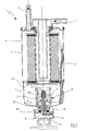
- Figure 1 shows a filter 1, substantially of known type, comprising an outer casing 2 having a fuel inlet 3 and outlet 4. Said casing 2 houses internally a filter means 5 positioned within an upper chamber 6. The fuel enters the chamber 6 through the inlet 3 and after passing through the filter means 5 leaves through the outlet 4.
- a chamber 7 separated from the former by a perforated base 50, which also acts as a support element for the filter means 5.
- the chamber 7 serves to collect the water which separates from the fuel and is therefore filled with fuel in its upper part, the separated water accumulating in the lower part.
- a water level sensor 8 comprising a float 9, the specific gravity of which lies between the specific gravity of water and that of the fuel, and which is positioned in the collection chamber 7 under the influence of the level of the water A which collects on the bottom.
- the float 9 is slidable along a vertical guide stem 12, which projects into the chamber 7 by passing through a lower port 70 located at the lowest point of the chamber and closed by the stem 12 in collaboration with a seal gasket 122.
- a magnetic field sensor element 13 for example of reed or Hall type, which is activated when the float, in moving upwards as the level of the accumulated water increases, reaches a position in correspondence with the element 13.
- the sensor element 13 is electrically connected to an electronic card 14 by two connection cables 130 and 131. Said card is connected to the engine control unit. When, by the effect of the water collected in the chamber 6, the float 10 reaches the level of the sensor 13, an electrical signal is generated and by way of the two conductor cables 130 and 131 is sensed by the electronic card 14, which makes it available to the engine electronic control unit, to warn the user by a warning lamp positioned on the vehicle dashboard or by a different warning signal.
- control card 14 activates withdrawal means for the water collected in the chamber 7.
- Said water withdrawal means are associated with the lower end of the filter 1, but are not illustrated or described in detail as they are of known type.
- a temperature sensor 15 embedded in a layer of conductive resin 150, to measure the temperature of the fuel present in the chamber 7, this being equal to or at least indicative of the temperature of the fuel passing through the filter 1.
- the sensor 15 for example of NTC type, is connected to the electronic card by two conductors 16 and 17.
- the temperature value measured by the sensor 15 is fed to the engine electronic control unit via the card 14.
- Figure 3 shows a variant of the invention in which one of the conductor cables connecting the sensor to the card 14 is also used as the conductor cable connecting the sensor 15 to the card itself. Hence in this case there is simplification of the electrical circuit connecting the sensors to the card as the cable 20 is used as a common conductor.
Abstract
Description
- This invention relates to a filter for vehicle fuel, in particular for diesel engines of common rail or high pressure direct injection type, and the like.
- In these types of engine the fuel feed rate to the engine feed pump is much greater than that required by the engine for its operation, as the fuel is used not only as engine feed fluid but also as the lubrication fluid and cooling fluid for the feed pump. That fuel not fed to the cylinders increases in temperature as it removes heat from the pump and is then returned to the vehicle fuel tank.
- It has been found that because of the high temperature at which the feed pump operates, after a certain time of engine operation the fuel contained in the vehicle tank or in the engine feed circuit attains a high temperature, of the order of 100°C and beyond.
- A requirement has therefore arisen to control the fuel temperature as too high a fuel temperature could damage components of the engine feed circuit. Moreover in these types of engine the fuel temperature has become an essential parameter in regulating the fuel feed rate to the engine. Measuring the fuel temperature has hence become necessary for correct engine operation. The value of the measured temperature is fed to the electronic control unit which controls fuel feed to the pump and hence to the cylinders.
- The known art has solved this need to control the fuel temperature by temperature measurement devices positioned either inside the fuel tank or along the conduits through which the fuel is fed to the engine.
- In both cases the devices used require suitable fixing flanges and electric cables for connecting the device to the vehicle electronic control unit.
- Moreover it is often difficult to install said temperature measurement devices as that engine region in which the conduits are present is crowded with numerous components.
- The object of the present invention is to overcome the drawbacks of the known art within the context of a simple and rational solution of low cost.
- The invention attains said object by virtue of the characteristics defined in the claims.
- Specifically, the invention provides a temperature measurement device which is associated with the lower part of the fuel filter installed on the vehicle.
- According to a preferred embodiment of the invention, said temperature measurement device is associated with the means for sensing the presence of water accumulated in the bottom of the fuel filter.
- In this respect it is known that the water present in the fuel tends to create oxidation damage to the metal parts with which it comes into contact, hence the latest generation of filters, in particular for diesel engine fuel, separate not only the impurities but also the water present in the fuel.
- As water has a specific gravity greater than the fuel, it collects on the bottom of a collection chamber positioned in the lower part of the filter.
- This water must be bled off on reaching a maximum level, to avoid it interfering with correct filter operation, or it may be returned to the fuel flow leaving the filter.
- The water is bled off by suitable means which are activated when a suitable sensor senses that the water in said collection chamber has reached its maximum level.
- Said means for sensing the water level comprise a float positioned within the collection chamber and having a specific gravity between the specific gravity of water and the specific gravity of the fuel. The float is mounted on a guide stem, in the interior of which a magnetic field sensor is positioned connected electrically to an electronic card by two conductors. The prior art document US 4.580.542 shows a fuel filter with such a water level sensor.
- According to the invention, said stem also internally houses the temperature sensor which measures the fuel temperature. Specifically, said temperature sensor is housed in proximity to the free end of the stem, which projects into the water collection chamber. To facilitate heat conduction the sensor is embedded in a conductive resin which is poured into the stem.
- The invention is described in detail hereinafter with the aid of the accompanying figures, which illustrate a non-exclusive embodiment thereof by way of example.
- Figure 1 is a schematic illustration of the filter according to the invention;
- Figure 2 is an enlarged view of the lower portion of Figure 1;
- Figure 3 is an enlarged view of the lower portion of the filter, on which a variant of the invention is installed.
- Figure 1 shows a filter 1, substantially of known type, comprising an
outer casing 2 having afuel inlet 3 andoutlet 4. Saidcasing 2 houses internally a filter means 5 positioned within anupper chamber 6. The fuel enters thechamber 6 through theinlet 3 and after passing through the filter means 5 leaves through theoutlet 4. - Below the
chamber 6 and communicating therewith there is positioned achamber 7 separated from the former by aperforated base 50, which also acts as a support element for the filter means 5. - The
chamber 7 serves to collect the water which separates from the fuel and is therefore filled with fuel in its upper part, the separated water accumulating in the lower part. - On the base of the
chamber 7 there is positioned awater level sensor 8 comprising afloat 9, the specific gravity of which lies between the specific gravity of water and that of the fuel, and which is positioned in thecollection chamber 7 under the influence of the level of the water A which collects on the bottom. Thefloat 9 is slidable along avertical guide stem 12, which projects into thechamber 7 by passing through alower port 70 located at the lowest point of the chamber and closed by thestem 12 in collaboration with aseal gasket 122. - In the interior of the
stem 12 there is positioned a magneticfield sensor element 13, for example of reed or Hall type, which is activated when the float, in moving upwards as the level of the accumulated water increases, reaches a position in correspondence with theelement 13. - The
sensor element 13 is electrically connected to anelectronic card 14 by twoconnection cables chamber 6, the float 10 reaches the level of thesensor 13, an electrical signal is generated and by way of the twoconductor cables electronic card 14, which makes it available to the engine electronic control unit, to warn the user by a warning lamp positioned on the vehicle dashboard or by a different warning signal. - When the water maximum level signal is generated, the
control card 14 activates withdrawal means for the water collected in thechamber 7. Said water withdrawal means are associated with the lower end of the filter 1, but are not illustrated or described in detail as they are of known type. - In the interior of the
stem 12, in proximity to its free end, there is also present atemperature sensor 15 embedded in a layer ofconductive resin 150, to measure the temperature of the fuel present in thechamber 7, this being equal to or at least indicative of the temperature of the fuel passing through the filter 1. - The
sensor 15, for example of NTC type, is connected to the electronic card by twoconductors sensor 15 is fed to the engine electronic control unit via thecard 14. - Figure 3 shows a variant of the invention in which one of the conductor cables connecting the sensor to the
card 14 is also used as the conductor cable connecting thesensor 15 to the card itself. Hence in this case there is simplification of the electrical circuit connecting the sensors to the card as thecable 20 is used as a common conductor.
Claims (5)
- A fuel filter (1) or diesel engines with high pressure direct injection of common rail type and the like, comprising an outer casing (2) provided with a fuel inlet conduit (3) and an outlet conduit (4), and internally housing a filter means (5) said casing (2) comprising an upper chamber (6) for containing said filter means, a lower chamber (7) communicating with said upper chamber (6) to collect the water which said filter means (5) separates from the fuel, and means (8) for measuring the level of the water collected in the lower chamber (7), characterised in that said means (8) for measuring the water level in the chamber (7) comprises a temperature sensor (15) for generating an electrical signal, said signal being fed to an electronic card (14) by two conductors (16, 17).
- A filter as claimed in claim 1 characterised in that said level sensor means comprises a float (9) positioned in the collection chamber and having a specific gravity between the specific gravity of water and that of the fuel, and a float guide stem (12) in the interior of which there is positioned a magnetic field sensor (13) connected electrically to said electronic card (14) by two conductors (16, 17) said temperature sensor means (15) being positioned in the interior of said stem (12) in proximity to its upper free end.
- A filter as claimed in claim 2 characterised in that one of the conductors (16, 17) connecting said temperature sensor means to said card is also connected to said magnetic field sensor (13).
- A filter as claimed in claim 1, characterised in that said temperature sensor (15) is of NTC type.
- A filter as claimed in claim 1, characterised in that said temperature sensor (15) is embedded in a layer of conductive resin (150).
Priority Applications (1)
| Application Number | Priority Date | Filing Date | Title |
|---|---|---|---|
| SI200330349T SI1567762T2 (en) | 2002-12-03 | 2003-10-24 | Fuel filter for diesel engines with high pressure direct injection of common rail type and the like |
Applications Claiming Priority (3)
| Application Number | Priority Date | Filing Date | Title |
|---|---|---|---|
| IT000094A ITRE20020094A1 (en) | 2002-12-03 | 2002-12-03 | FUEL FILTER FOR DIRECT INJECTION DIESEL ENGINES |
| ITRE20020094 | 2002-12-03 | ||
| PCT/EP2003/012059 WO2004051070A1 (en) | 2002-12-03 | 2003-10-24 | Fuel filter for diesel engines with high pressure direct injection of common rail type and the like |
Publications (3)
| Publication Number | Publication Date |
|---|---|
| EP1567762A1 EP1567762A1 (en) | 2005-08-31 |
| EP1567762B1 true EP1567762B1 (en) | 2006-04-12 |
| EP1567762B2 EP1567762B2 (en) | 2011-11-09 |
Family
ID=11454291
Family Applications (1)
| Application Number | Title | Priority Date | Filing Date |
|---|---|---|---|
| EP03769474A Expired - Lifetime EP1567762B2 (en) | 2002-12-03 | 2003-10-24 | Fuel filter for diesel engines with high pressure direct injection of common rail type and the like |
Country Status (23)
| Country | Link |
|---|---|
| US (1) | US7476310B2 (en) |
| EP (1) | EP1567762B2 (en) |
| JP (1) | JP4461020B2 (en) |
| KR (1) | KR100984294B1 (en) |
| CN (1) | CN100497926C (en) |
| AT (1) | ATE323226T1 (en) |
| AU (1) | AU2003278159A1 (en) |
| BR (1) | BR0315656B1 (en) |
| CA (1) | CA2504033C (en) |
| DE (2) | DE03769474T1 (en) |
| ES (1) | ES2239931T3 (en) |
| HK (1) | HK1084432A1 (en) |
| HR (1) | HRP20050338B1 (en) |
| IT (1) | ITRE20020094A1 (en) |
| MX (1) | MXPA05005299A (en) |
| NO (1) | NO337661B1 (en) |
| PL (1) | PL202320B1 (en) |
| PT (1) | PT1567762E (en) |
| RU (1) | RU2345241C2 (en) |
| SI (1) | SI1567762T2 (en) |
| TN (1) | TNSN05103A1 (en) |
| UA (1) | UA83811C2 (en) |
| WO (1) | WO2004051070A1 (en) |
Families Citing this family (19)
| Publication number | Priority date | Publication date | Assignee | Title |
|---|---|---|---|---|
| CN101472654B (en) | 2006-06-20 | 2015-06-10 | 卡明斯过滤Ip有限公司 | Replaceable filter elements including plural filter media and related filtration systems, tecniques and methods |
| DE102006046209B4 (en) * | 2006-09-29 | 2008-08-28 | Siemens Ag | Apparatus and method for damage analysis of a fuel supply system |
| ITTO20060744A1 (en) * | 2006-10-16 | 2008-04-17 | All Consulting Srl | FILTER FOR INTERNAL COMBUSTION ENGINES |
| US8132675B2 (en) | 2007-12-05 | 2012-03-13 | Baldwin Filters, Inc. | Filter having baseplate with internal gasket location |
| US20100059344A1 (en) * | 2008-09-10 | 2010-03-11 | Ken Belanger | Liquid level sensor |
| US20100180811A1 (en) * | 2009-01-21 | 2010-07-22 | George Sotiriou | Water level detector |
| IT1396707B1 (en) * | 2009-07-06 | 2012-12-14 | Ufi Filters Spa | IMPROVED FILTER UNIT FOR DIESEL ENGINES WITH DIESEL DEVICE |
| RU2478823C2 (en) * | 2009-09-08 | 2013-04-10 | Федеральное государственное унитарное предприятие "Центральный ордена Трудового Красного Знамени научно-исследовательский автомобильный и автомоторный институт "НАМИ" | Biofuel coarse filter |
| DE102010022195A1 (en) * | 2010-05-20 | 2011-11-24 | Mahle International Gmbh | Wasseraustragseinrichtung |
| IT1404008B1 (en) * | 2011-02-04 | 2013-11-08 | Ufi Filters Spa | COMPONENT FOR FILTERS |
| KR101280336B1 (en) * | 2011-02-08 | 2013-07-01 | (주)유민에쓰티 | Water level sensing apparatus for water separator |
| RU2478822C1 (en) * | 2011-12-08 | 2013-04-10 | Федеральное государственное бюджетное образовательное учреждение высшего профессионального образования "Пензенская государственная сельскохозяйственная академия" | Combined fuel filter |
| ITRE20120066A1 (en) * | 2012-10-11 | 2014-04-12 | Ufi Filters Spa | FILTERING CARTRIDGE EQUIPPED WITH MEANS FOR PURGE OF WATER AND RELATIVE FILTERING UNIT |
| ITRE20130066A1 (en) * | 2013-09-19 | 2015-03-20 | Ufi Filters Spa | FILTER UNIT WITH SENSOR OF WATER IN THE DIESEL FUEL |
| CN106930878A (en) * | 2015-12-30 | 2017-07-07 | 上海欧菲滤清器有限公司 | Fuel filter |
| DE102016005271B4 (en) * | 2016-04-29 | 2019-10-02 | Mann+Hummel Gmbh | Drain control device for a filter system and filter system with a drain control device |
| DE102016005270B4 (en) * | 2016-04-29 | 2019-09-05 | Mann+Hummel Gmbh | Drain control device for a filter system and filter system with a drain control device |
| GB2555448B (en) * | 2016-10-28 | 2021-06-09 | Perkins Engines Co Ltd | Fuel filter with water sensor, and sensor therefor |
| DE102017010017A1 (en) * | 2017-10-27 | 2019-05-02 | Mann+Hummel Gmbh | Drain control device for a filter system and filter system with a drain control device |
Family Cites Families (10)
| Publication number | Priority date | Publication date | Assignee | Title |
|---|---|---|---|---|
| JPS5939179Y2 (en) * | 1979-06-21 | 1984-10-31 | 日産自動車株式会社 | Diesel engine fuel filter device |
| US4539109A (en) † | 1983-02-01 | 1985-09-03 | Davco Manufacturing Corporation | Drain system for fuel processor apparatus |
| US4502955A (en) * | 1983-04-14 | 1985-03-05 | Racor Industries, Inc. | Filter assembly |
| US4680110A (en) * | 1984-01-23 | 1987-07-14 | Davco Manufacturing Corporation | Filter block mounted fuel processor apparatus |
| US4580542A (en) * | 1984-02-14 | 1986-04-08 | Aisin Seiki Kabushiki Kaisha | Fuel heater and fuel contamination detecting apparatus |
| US5201223A (en) * | 1988-05-02 | 1993-04-13 | Fluid Components, Inc. | Method of sensing fluid flow and level employing a heated extended resistance temperature sensor |
| DE4237546C2 (en) * | 1992-11-06 | 2003-10-16 | Behr Thermot Tronik Gmbh | Electrical switching device |
| US6208254B1 (en) * | 1999-09-15 | 2001-03-27 | Fluid Components Intl | Thermal dispersion mass flow rate and liquid level switch/transmitter |
| US6471853B1 (en) * | 2000-11-22 | 2002-10-29 | Pti Technologies, Inc. | Prognostic health monitoring of fluidic systems using MEMS technology |
| CN2497068Y (en) * | 2001-08-21 | 2002-06-26 | 张荣军 | Temperature-controlled diesel filter |
-
2002
- 2002-12-03 IT IT000094A patent/ITRE20020094A1/en unknown
-
2003
- 2003-10-24 PL PL375273A patent/PL202320B1/en unknown
- 2003-10-24 MX MXPA05005299A patent/MXPA05005299A/en active IP Right Grant
- 2003-10-24 CN CNB2003801017090A patent/CN100497926C/en not_active Expired - Lifetime
- 2003-10-24 US US10/531,273 patent/US7476310B2/en not_active Expired - Fee Related
- 2003-10-24 EP EP03769474A patent/EP1567762B2/en not_active Expired - Lifetime
- 2003-10-24 PT PT03769474T patent/PT1567762E/en unknown
- 2003-10-24 JP JP2004556097A patent/JP4461020B2/en not_active Expired - Fee Related
- 2003-10-24 WO PCT/EP2003/012059 patent/WO2004051070A1/en active IP Right Grant
- 2003-10-24 UA UAA200504960A patent/UA83811C2/en unknown
- 2003-10-24 DE DE03769474T patent/DE03769474T1/en active Pending
- 2003-10-24 AU AU2003278159A patent/AU2003278159A1/en not_active Abandoned
- 2003-10-24 SI SI200330349T patent/SI1567762T2/en unknown
- 2003-10-24 ES ES03769474T patent/ES2239931T3/en not_active Expired - Lifetime
- 2003-10-24 RU RU2005116021/06A patent/RU2345241C2/en not_active IP Right Cessation
- 2003-10-24 DE DE60304605T patent/DE60304605T2/en not_active Expired - Lifetime
- 2003-10-24 CA CA2504033A patent/CA2504033C/en not_active Expired - Fee Related
- 2003-10-24 AT AT03769474T patent/ATE323226T1/en active
- 2003-10-24 BR BRPI0315656-7A patent/BR0315656B1/en not_active IP Right Cessation
- 2003-10-24 KR KR1020057007220A patent/KR100984294B1/en active IP Right Grant
-
2005
- 2005-04-05 NO NO20051679A patent/NO337661B1/en not_active IP Right Cessation
- 2005-04-08 TN TNP2005000103A patent/TNSN05103A1/en unknown
- 2005-04-14 HR HRP20050338AA patent/HRP20050338B1/en not_active IP Right Cessation
-
2006
- 2006-04-13 HK HK06104529.6A patent/HK1084432A1/en not_active IP Right Cessation
Also Published As
Similar Documents
| Publication | Publication Date | Title |
|---|---|---|
| EP1567762B1 (en) | Fuel filter for diesel engines with high pressure direct injection of common rail type and the like | |
| EP1750824B1 (en) | Fuel filter for diesel internal combustion engines | |
| US10010815B2 (en) | Fuel filter of an internal combustion engine and heating sensor module of a fuel filter | |
| EP1899596B1 (en) | Fuel filter unit for diesel internal combustion engines | |
| JP2009180159A (en) | Fuel property sensor | |
| US20170298881A1 (en) | Integrated smart fuel filtration system | |
| WO2016205797A1 (en) | Brushless dc motor control with integrated water in filter circuitry | |
| CN102548633A (en) | An improved filter group for diesel-powered internal combustion engines with a heater device | |
| CA1242017A (en) | Heater and water probe | |
| EP3046646B1 (en) | A filter group with a presence sensor of water in diesel fuel | |
| CN209354282U (en) | Integrate the fuel filter of heater, water level sensor and temperature sensor | |
| CN210833766U (en) | Integrated liquid level sensor | |
| KR101941603B1 (en) | Fuel filter for diesel engine | |
| EP3209404B1 (en) | Integrated smart fuel filtration system | |
| CN113357064A (en) | Diesel filter | |
| CN114839494A (en) | Sleeve flashover characteristic measuring device considering humidity influence |
Legal Events
| Date | Code | Title | Description |
|---|---|---|---|
| PUAI | Public reference made under article 153(3) epc to a published international application that has entered the european phase |
Free format text: ORIGINAL CODE: 0009012 |
|
| 17P | Request for examination filed |
Effective date: 20050408 |
|
| AK | Designated contracting states |
Kind code of ref document: A1 Designated state(s): AT BE BG CH CY CZ DE DK EE ES FI FR GB GR HU IE IT LI LU MC NL PT RO SE SI SK TR |
|
| AX | Request for extension of the european patent |
Extension state: AL LT LV MK |
|
| GRAP | Despatch of communication of intention to grant a patent |
Free format text: ORIGINAL CODE: EPIDOSNIGR1 |
|
| DET | De: translation of patent claims | ||
| GRAS | Grant fee paid |
Free format text: ORIGINAL CODE: EPIDOSNIGR3 |
|
| GRAA | (expected) grant |
Free format text: ORIGINAL CODE: 0009210 |
|
| AK | Designated contracting states |
Kind code of ref document: B1 Designated state(s): AT BE BG CH CY CZ DE DK EE ES FI FR GB GR HU IE IT LI LU MC NL PT RO SE SI SK TR |
|
| AX | Request for extension of the european patent |
Extension state: AL LT LV MK |
|
| PG25 | Lapsed in a contracting state [announced via postgrant information from national office to epo] |
Ref country code: IT Free format text: LAPSE BECAUSE OF FAILURE TO SUBMIT A TRANSLATION OF THE DESCRIPTION OR TO PAY THE FEE WITHIN THE PRESCRIBED TIME-LIMIT;WARNING: LAPSES OF ITALIAN PATENTS WITH EFFECTIVE DATE BEFORE 2007 MAY HAVE OCCURRED AT ANY TIME BEFORE 2007. THE CORRECT EFFECTIVE DATE MAY BE DIFFERENT FROM THE ONE RECORDED. Effective date: 20060412 Ref country code: FI Free format text: LAPSE BECAUSE OF FAILURE TO SUBMIT A TRANSLATION OF THE DESCRIPTION OR TO PAY THE FEE WITHIN THE PRESCRIBED TIME-LIMIT Effective date: 20060412 Ref country code: LI Free format text: LAPSE BECAUSE OF FAILURE TO SUBMIT A TRANSLATION OF THE DESCRIPTION OR TO PAY THE FEE WITHIN THE PRESCRIBED TIME-LIMIT Effective date: 20060412 Ref country code: CH Free format text: LAPSE BECAUSE OF FAILURE TO SUBMIT A TRANSLATION OF THE DESCRIPTION OR TO PAY THE FEE WITHIN THE PRESCRIBED TIME-LIMIT Effective date: 20060412 |
|
| REG | Reference to a national code |
Ref country code: GB Ref legal event code: FG4D |
|
| REG | Reference to a national code |
Ref country code: CH Ref legal event code: EP |
|
| REG | Reference to a national code |
Ref country code: RO Ref legal event code: EPE |
|
| REF | Corresponds to: |
Ref document number: 60304605 Country of ref document: DE Date of ref document: 20060524 Kind code of ref document: P |
|
| REG | Reference to a national code |
Ref country code: IE Ref legal event code: FG4D |
|
| REG | Reference to a national code |
Ref country code: HU Ref legal event code: AG4A Ref document number: E000350 Country of ref document: HU |
|
| REG | Reference to a national code |
Ref country code: GR Ref legal event code: EP Ref document number: 20060401767 Country of ref document: GR |
|
| PG25 | Lapsed in a contracting state [announced via postgrant information from national office to epo] |
Ref country code: SE Free format text: LAPSE BECAUSE OF FAILURE TO SUBMIT A TRANSLATION OF THE DESCRIPTION OR TO PAY THE FEE WITHIN THE PRESCRIBED TIME-LIMIT Effective date: 20060712 Ref country code: DK Free format text: LAPSE BECAUSE OF FAILURE TO SUBMIT A TRANSLATION OF THE DESCRIPTION OR TO PAY THE FEE WITHIN THE PRESCRIBED TIME-LIMIT Effective date: 20060712 |
|
| REG | Reference to a national code |
Ref country code: PT Ref legal event code: SC4A Effective date: 20060510 |
|
| LTIE | Lt: invalidation of european patent or patent extension |
Effective date: 20060412 |
|
| ET | Fr: translation filed | ||
| REG | Reference to a national code |
Ref country code: CH Ref legal event code: PL |
|
| REG | Reference to a national code |
Ref country code: ES Ref legal event code: FG2A Ref document number: 2239931 Country of ref document: ES Kind code of ref document: T3 |
|
| PLBI | Opposition filed |
Free format text: ORIGINAL CODE: 0009260 |
|
| 26 | Opposition filed |
Opponent name: MAHLE INTERNATIONAL GMBH Effective date: 20061118 |
|
| PLAX | Notice of opposition and request to file observation + time limit sent |
Free format text: ORIGINAL CODE: EPIDOSNOBS2 |
|
| NLR1 | Nl: opposition has been filed with the epo |
Opponent name: MAHLE INTERNATIONAL GMBH |
|
| PLBI | Opposition filed |
Free format text: ORIGINAL CODE: 0009260 |
|
| 26 | Opposition filed |
Opponent name: MAHLE INTERNATIONAL GMBH Effective date: 20061118 Opponent name: ROBERT BOSCH GMBH Effective date: 20070111 |
|
| NLR1 | Nl: opposition has been filed with the epo |
Opponent name: MAHLE INTERNATIONAL GMBH Opponent name: ROBERT BOSCH GMBH |
|
| PLBB | Reply of patent proprietor to notice(s) of opposition received |
Free format text: ORIGINAL CODE: EPIDOSNOBS3 |
|
| PG25 | Lapsed in a contracting state [announced via postgrant information from national office to epo] |
Ref country code: CY Free format text: LAPSE BECAUSE OF FAILURE TO SUBMIT A TRANSLATION OF THE DESCRIPTION OR TO PAY THE FEE WITHIN THE PRESCRIBED TIME-LIMIT Effective date: 20060412 |
|
| PGFP | Annual fee paid to national office [announced via postgrant information from national office to epo] |
Ref country code: DE Payment date: 20101105 Year of fee payment: 8 |
|
| PUAH | Patent maintained in amended form |
Free format text: ORIGINAL CODE: 0009272 |
|
| STAA | Information on the status of an ep patent application or granted ep patent |
Free format text: STATUS: PATENT MAINTAINED AS AMENDED |
|
| 27A | Patent maintained in amended form |
Effective date: 20111109 |
|
| AK | Designated contracting states |
Kind code of ref document: B2 Designated state(s): AT BE BG CH CY CZ DE DK EE ES FI FR GB GR HU IE IT LI LU MC NL PT RO SE SI SK TR |
|
| AX | Request for extension of the european patent |
Extension state: AL LT LV MK |
|
| REG | Reference to a national code |
Ref country code: DE Ref legal event code: R102 Ref document number: 60304605 Country of ref document: DE |
|
| REG | Reference to a national code |
Ref country code: DE Ref legal event code: R102 Ref document number: 60304605 Country of ref document: DE Effective date: 20111109 |
|
| REG | Reference to a national code |
Ref country code: NL Ref legal event code: T3 |
|
| REG | Reference to a national code |
Ref country code: DE Ref legal event code: R135 Ref document number: 60304605 Country of ref document: DE |
|
| REG | Reference to a national code |
Ref country code: EE Ref legal event code: LD4A Ref document number: E000371 Country of ref document: EE |
|
| REG | Reference to a national code |
Ref country code: SK Ref legal event code: T5 Ref document number: E 728 Country of ref document: SK |
|
| REG | Reference to a national code |
Ref country code: GR Ref legal event code: EP Ref document number: 20120400351 Country of ref document: GR Effective date: 20120322 |
|
| PGFP | Annual fee paid to national office [announced via postgrant information from national office to epo] |
Ref country code: ES Payment date: 20121026 Year of fee payment: 10 |
|
| REG | Reference to a national code |
Ref country code: DE Ref legal event code: R073 Ref document number: 60304605 Country of ref document: DE |
|
| REG | Reference to a national code |
Ref country code: DE Ref legal event code: R073 Ref document number: 60304605 Country of ref document: DE |
|
| PG25 | Lapsed in a contracting state [announced via postgrant information from national office to epo] |
Ref country code: ES Free format text: LAPSE BECAUSE OF FAILURE TO SUBMIT A TRANSLATION OF THE DESCRIPTION OR TO PAY THE FEE WITHIN THE PRESCRIBED TIME-LIMIT Effective date: 20060723 |
|
| PG25 | Lapsed in a contracting state [announced via postgrant information from national office to epo] |
Ref country code: DE Free format text: LAPSE BECAUSE OF FAILURE TO SUBMIT A TRANSLATION OF THE DESCRIPTION OR TO PAY THE FEE WITHIN THE PRESCRIBED TIME-LIMIT Effective date: 20120210 |
|
| PG25 | Lapsed in a contracting state [announced via postgrant information from national office to epo] |
Ref country code: ES Free format text: LAPSE BECAUSE OF FAILURE TO SUBMIT A TRANSLATION OF THE DESCRIPTION OR TO PAY THE FEE WITHIN THE PRESCRIBED TIME-LIMIT Effective date: 20120220 |
|
| REG | Reference to a national code |
Ref country code: DE Ref legal event code: R124 Ref document number: 60304605 Country of ref document: DE |
|
| REG | Reference to a national code |
Ref country code: DE Ref legal event code: R124 Ref document number: 60304605 Country of ref document: DE |
|
| REG | Reference to a national code |
Ref country code: FR Ref legal event code: PLFP Year of fee payment: 13 |
|
| REG | Reference to a national code |
Ref country code: FR Ref legal event code: PLFP Year of fee payment: 14 |
|
| REG | Reference to a national code |
Ref country code: FR Ref legal event code: PLFP Year of fee payment: 15 |
|
| REG | Reference to a national code |
Ref country code: FR Ref legal event code: PLFP Year of fee payment: 16 |
|
| PG25 | Lapsed in a contracting state [announced via postgrant information from national office to epo] |
Ref country code: ES Free format text: THE PATENT HAS BEEN ANNULLED BY A DECISION OF A NATIONAL AUTHORITY Effective date: 20120220 |
|
| PGFP | Annual fee paid to national office [announced via postgrant information from national office to epo] |
Ref country code: LU Payment date: 20191028 Year of fee payment: 17 |
|
| PGFP | Annual fee paid to national office [announced via postgrant information from national office to epo] |
Ref country code: RO Payment date: 20191004 Year of fee payment: 17 Ref country code: BG Payment date: 20191018 Year of fee payment: 17 Ref country code: PT Payment date: 20191008 Year of fee payment: 17 Ref country code: NL Payment date: 20191026 Year of fee payment: 17 Ref country code: CZ Payment date: 20191011 Year of fee payment: 17 Ref country code: MC Payment date: 20191003 Year of fee payment: 17 Ref country code: HU Payment date: 20191008 Year of fee payment: 17 Ref country code: IE Payment date: 20191028 Year of fee payment: 17 Ref country code: SK Payment date: 20191002 Year of fee payment: 17 |
|
| PGFP | Annual fee paid to national office [announced via postgrant information from national office to epo] |
Ref country code: EE Payment date: 20191003 Year of fee payment: 17 Ref country code: GR Payment date: 20191029 Year of fee payment: 17 Ref country code: SI Payment date: 20191002 Year of fee payment: 17 Ref country code: BE Payment date: 20191028 Year of fee payment: 17 Ref country code: FR Payment date: 20191025 Year of fee payment: 17 |
|
| PGFP | Annual fee paid to national office [announced via postgrant information from national office to epo] |
Ref country code: TR Payment date: 20191004 Year of fee payment: 17 Ref country code: AT Payment date: 20191002 Year of fee payment: 17 |
|
| PGFP | Annual fee paid to national office [announced via postgrant information from national office to epo] |
Ref country code: GB Payment date: 20191028 Year of fee payment: 17 |
|
| REG | Reference to a national code |
Ref country code: EE Ref legal event code: HC1A Ref document number: E000371 Country of ref document: EE |
|
| PGFP | Annual fee paid to national office [announced via postgrant information from national office to epo] |
Ref country code: IT Payment date: 20201028 Year of fee payment: 18 |
|
| REG | Reference to a national code |
Ref country code: EE Ref legal event code: MM4A Ref document number: E000371 Country of ref document: EE Effective date: 20201031 |
|
| REG | Reference to a national code |
Ref country code: NL Ref legal event code: MM Effective date: 20201101 |
|
| REG | Reference to a national code |
Ref country code: AT Ref legal event code: MM01 Ref document number: 323226 Country of ref document: AT Kind code of ref document: T Effective date: 20201024 |
|
| GBPC | Gb: european patent ceased through non-payment of renewal fee |
Effective date: 20201024 |
|
| REG | Reference to a national code |
Ref country code: SK Ref legal event code: MM4A Ref document number: E 728 Country of ref document: SK Effective date: 20201024 |
|
| PG25 | Lapsed in a contracting state [announced via postgrant information from national office to epo] |
Ref country code: MC Free format text: LAPSE BECAUSE OF NON-PAYMENT OF DUE FEES Effective date: 20201103 Ref country code: LU Free format text: LAPSE BECAUSE OF NON-PAYMENT OF DUE FEES Effective date: 20201024 |
|
| REG | Reference to a national code |
Ref country code: BE Ref legal event code: MM Effective date: 20201031 |
|
| PG25 | Lapsed in a contracting state [announced via postgrant information from national office to epo] |
Ref country code: EE Free format text: LAPSE BECAUSE OF NON-PAYMENT OF DUE FEES Effective date: 20201031 Ref country code: BG Free format text: LAPSE BECAUSE OF NON-PAYMENT OF DUE FEES Effective date: 20210430 Ref country code: CZ Free format text: LAPSE BECAUSE OF NON-PAYMENT OF DUE FEES Effective date: 20201024 Ref country code: NL Free format text: LAPSE BECAUSE OF NON-PAYMENT OF DUE FEES Effective date: 20201101 Ref country code: SK Free format text: LAPSE BECAUSE OF NON-PAYMENT OF DUE FEES Effective date: 20201024 Ref country code: PT Free format text: LAPSE BECAUSE OF NON-PAYMENT OF DUE FEES Effective date: 20210426 Ref country code: RO Free format text: LAPSE BECAUSE OF NON-PAYMENT OF DUE FEES Effective date: 20201024 Ref country code: FR Free format text: LAPSE BECAUSE OF NON-PAYMENT OF DUE FEES Effective date: 20201031 Ref country code: GR Free format text: LAPSE BECAUSE OF NON-PAYMENT OF DUE FEES Effective date: 20210510 |
|
| PG25 | Lapsed in a contracting state [announced via postgrant information from national office to epo] |
Ref country code: BE Free format text: LAPSE BECAUSE OF NON-PAYMENT OF DUE FEES Effective date: 20201031 Ref country code: AT Free format text: LAPSE BECAUSE OF NON-PAYMENT OF DUE FEES Effective date: 20201024 Ref country code: SI Free format text: LAPSE BECAUSE OF NON-PAYMENT OF DUE FEES Effective date: 20201025 Ref country code: HU Free format text: LAPSE BECAUSE OF NON-PAYMENT OF DUE FEES Effective date: 20201025 Ref country code: GB Free format text: LAPSE BECAUSE OF NON-PAYMENT OF DUE FEES Effective date: 20201024 |
|
| REG | Reference to a national code |
Ref country code: SI Ref legal event code: KO00 Effective date: 20210812 |
|
| PG25 | Lapsed in a contracting state [announced via postgrant information from national office to epo] |
Ref country code: IE Free format text: LAPSE BECAUSE OF NON-PAYMENT OF DUE FEES Effective date: 20201024 |
|
| PG25 | Lapsed in a contracting state [announced via postgrant information from national office to epo] |
Ref country code: TR Free format text: LAPSE BECAUSE OF NON-PAYMENT OF DUE FEES Effective date: 20201024 |
|
| PG25 | Lapsed in a contracting state [announced via postgrant information from national office to epo] |
Ref country code: IT Free format text: LAPSE BECAUSE OF NON-PAYMENT OF DUE FEES Effective date: 20211031 |
|
| P01 | Opt-out of the competence of the unified patent court (upc) registered |
Effective date: 20230711 |