EP1567273B1 - Dechiqueteur - Google Patents
Dechiqueteur Download PDFInfo
- Publication number
- EP1567273B1 EP1567273B1 EP03775434A EP03775434A EP1567273B1 EP 1567273 B1 EP1567273 B1 EP 1567273B1 EP 03775434 A EP03775434 A EP 03775434A EP 03775434 A EP03775434 A EP 03775434A EP 1567273 B1 EP1567273 B1 EP 1567273B1
- Authority
- EP
- European Patent Office
- Prior art keywords
- shredder
- press
- wear surface
- feeding chamber
- rotor
- Prior art date
- Legal status (The legal status is an assumption and is not a legal conclusion. Google has not performed a legal analysis and makes no representation as to the accuracy of the status listed.)
- Expired - Lifetime
Links
- 239000000463 material Substances 0.000 claims abstract description 25
- 238000005524 ceramic coating Methods 0.000 claims description 3
- 238000009434 installation Methods 0.000 claims description 3
- 238000005266 casting Methods 0.000 description 1
- 239000002184 metal Substances 0.000 description 1
- 239000004576 sand Substances 0.000 description 1
- 238000007789 sealing Methods 0.000 description 1
- 239000007787 solid Substances 0.000 description 1
Images

Classifications
-
- B—PERFORMING OPERATIONS; TRANSPORTING
- B02—CRUSHING, PULVERISING, OR DISINTEGRATING; PREPARATORY TREATMENT OF GRAIN FOR MILLING
- B02C—CRUSHING, PULVERISING, OR DISINTEGRATING IN GENERAL; MILLING GRAIN
- B02C18/00—Disintegrating by knives or other cutting or tearing members which chop material into fragments
- B02C18/06—Disintegrating by knives or other cutting or tearing members which chop material into fragments with rotating knives
- B02C18/16—Details
- B02C18/22—Feed or discharge means
- B02C18/2225—Feed means
- B02C18/2233—Feed means of ram or pusher type
Definitions
- the invention relates to a shredder for shredding material, the shredder comprising a frame, a shredder rotor rotatably arranged to the frame, a feeding chamber for directing the material to be shred into the shredder and for bringing the material in touch with the shredder rotor, a press arranged into the feeding chamber to perform substantially horizontal or pendulous motion for pushing the material towards the shredder rotor, whereby the press is arranged to move along a bottom structure of the feeding chamber.
- the capacity is increased by pushing material to be shred by means of a press against the surface of the shredder rotor in the shredder.
- the first shredding event takes place already when the material is ground between the shredder rotor and the press, while the actual shredding takes place later at the shredder rotor and the counter blades thereof.
- a known press solution is a box-like press, which is controlled using guide bars in a particular kind of tunnel provided with a straight bottom.
- the problem in such a structure is that fines end up between the box and the bottom structure, which causes buoyancy to the press, wear to the bottom structure and causes the press to wedge and to jam.
- Another known structure refers to a pendulous press, which may, if need be, move along a similar bottom structure.
- the advantage of the pendulum press is that the motion can be controlled more reliably but the drawback is the short distance. Further similar structures are known for example from characterising portion of claim 1.
- An advantage of the solution according to the invention is to even out the blows over a larger area and to stiffen the entire bottom structure and also that wear can now be focused to a changeable wear part. Compared with previous flat-bottom structures, a more precise adjustment can now be provided to compensate for wear, resulting in a reduction in wear and making the entry of, for instance, sand or a corresponding material between the press and the bottom structure more difficult.
- a shredder according to the invention comprises a frame 1, a shredder rotor 2 rotatably arranged to the frame, a feeding chamber 3 for directing the material to be shred (not shown) into the shredder and for bringing the material in touch with the shredder rotor 2, a press 4 arranged into the feeding chamber 3 to perform substantially horizontal or pendulous motion for pushing the material towards the shredder rotor 2, whereby the press 4 is arranged to move along a bottom structure 5 of the feeding chamber 3.
- the shredder rotor 2 and shredding elements 6 on the surface thereof are arranged to co-operate with counter blades 7 provided in the frame 1 and with a trough-like screen plate 8.
- the press 4 is also at the end of the pushing phase thereof involved in a similar co-operation with the shredder rotor 2 and the shredding elements 6 thereof.
- a conveyor belt 9 is arranged below the screen plate 8 for removing the shredded material falling through the screen plate 8.
- the feeding chamber 3 opens up as a "funnel-shaped" structure 10 upwards from the frame 1 and continues as a “tunnel-like” structure 11 within the frame 1 and is restricted at the bottom to the bottom structure 5.
- the funnel 10 may direct the material to be shred directly above the shredder rotor 2 and to the tunnel 11.
- the press 4 resembles a box-like piston, which is moved together with the material running in front of the piston by means of an appropriate drive unit (not shown) towards the shredder rotor 2 with such a force that the material is shred to a great extent before encountering the counter blades 7.
- the bottom structure 5, which basically forms a part of the frame structure of the shredder, is to be kept as a part that is not subjected to wear. As such it is subjected to rough and abrasive wear.
- the wear of the actual bottom structure 5 is presented in such a manner that a replaceable wear surface structure 12 is arranged on top of the bottom structure 5 at least substantially within the area covering the path of the lower surface of the press 4.
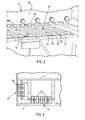
- the preferable wear surface structure 12 shown in Figure 2 comprises longitudinal ridges 13 in the direction of the path of the press 4 placed towards the shredder rotor 2 and longitudinal recesses 14 between the ridges 13.
- the cross-section of this structure may for instance be wavelike or angular, as shown in Figure 2 .
- the wear surface structure 12 may be formed of a plate or profile structure, for example of beams 13, which form the ridges, and the gaps thereof forming the recesses 14.
- the profiles required in this structure may be finished commercial products, different shapes bended of metal for this purpose or special solutions implemented by means of casting.
- At least the beams 13 concerned can preferably be arranged to the bottom structure 5 using a separate installation plate 15 to be provided between the two, in which case the beams 13 can at first be fastened to the installation plate 15, and then to mount the entire structure 13, 15 formed in this way to the bottom structure 5.
- the beams 13 can preferably be fastened using bolts 16, whereby an element structure is provided in which individual beams 13 subjected to wear can be replaced without having to replace the entire structure.
- the shape of a bottom part 18 of a front surface 17 in the press 4 is compatible with the cross-section profile of the wear surface structure 12, whereby it is preferable that the ridges 13 of the structure 12 taper upwards and the structure 12 is arranged to be adjustable, especially inclinable or to be lifted in relation to the bottom structure 5, in which case the wear occurring at the bottom part of the press 4 and/or in the structure 12 can be compensated, thus keeping the play between these parts as small as possible with simple adjusting measures.
- the wear resistance of the intermediate spaces 14 between the ridges 13 is to be improved, this can be carried out for instance using a ceramic coating.
- the ceramic coating poorly resists blows, and should therefore preferably be placed only between ridges 13 that endure wear.
- the wear surface structure 12 may also form a part of the guide structure of the press 4 from in such a manner that lower guide rollers 19 are fastened to the bottom of the press that move along the tracks formed of the intermediate spaces 14 and the ridges 13.
- Corresponding side guide rollers 20 can also be arranged on the side of the press 4 as well as a track arrangement, which may be similar to the wear surface structure 12. The movement of the press 4 is now considerably easier to handle without any impaction, which has often been a problem in presses provided with side steering only.
Landscapes
- Engineering & Computer Science (AREA)
- Food Science & Technology (AREA)
- Crushing And Pulverization Processes (AREA)
- Disintegrating Or Milling (AREA)
Claims (6)
- Déchiqueteur pour déchiqueter un matériau, le déchiqueteur comportant un bâti (1), un rotor déchiqueteur (2) monté rotatif sur le bâti, une chambre d'alimentation (3) pour diriger le matériau destiné à être déchiqueté dans le déchiqueteur et pour mettre le matériau en contact avec le rotor déchiqueteur, une presse (4) agencée dans la chambre d'alimentation pour effectuer un mouvement substantiellement horizontal ou pendulaire pour pousser le matériau en direction du rotor du déchiqueteur, la presse étant agencée pour se déplacer le long d'une structure inférieure (5) de la chambre d'alimentation, caractérisé en ce qu'une structure formant surface d'usure (12) remplaçable, comportant des arêtes longitudinales (13) disposées dans la direction du passage de la presse (4) allant vers le rotor déchiqueteur (2) et des cavités (14) agencées entre les arêtes, est agencée sur la partie supérieure de la structure inférieure (5) de la chambre d'alimentation (3) au moins substantiellement dans la zone couvrant le passage que comprend la surface inférieure de la presse, la structure formant surface d'usure (12) étant agencée pour être réglable, particulièrement pouvant être élevée ou inclinée par rapport à la surface inférieure (5).
- Déchiqueteur selon la revendication 1, caractérisé en ce que la section transversale de la structure formant surface d'usure (12) est ondulée ou angulaire.
- Déchiqueteur selon la revendication 1 ou la revendication 2, caractérisé en ce que la structure formant surface d'usure (12) est agencée sur la surface inférieure (5) en utilisant une plaque d'installation (15) séparée disposée entre ces dernières.
- Déchiqueteur selon l'une quelconque des revendications précédentes, caractérisé en ce que les arêtes (13) de la structure formant surface d'usure (12) présentent une section allant en décroissant vers le haut.
- Déchiqueteur selon l'une quelconque des revendications précédentes, caractérisé en ce que les cavités (14) de la structure formant surface d'usure (12) sont recouvertes d'un enduit céramique.
- Déchiqueteur selon l'une quelconque des revendications précédentes, caractérisé en ce que la structure formant surface d'usure (12) forme également une partie de la structure de guidage de la presse (4).
Applications Claiming Priority (3)
| Application Number | Priority Date | Filing Date | Title |
|---|---|---|---|
| FI20022146A FI118255B (fi) | 2002-12-04 | 2002-12-04 | Murskain |
| FI20022146 | 2002-12-04 | ||
| PCT/FI2003/000919 WO2004050250A1 (fr) | 2002-12-04 | 2003-12-02 | Dechiqueteur |
Publications (3)
| Publication Number | Publication Date |
|---|---|
| EP1567273A1 EP1567273A1 (fr) | 2005-08-31 |
| EP1567273B1 true EP1567273B1 (fr) | 2009-10-21 |
| EP1567273B9 EP1567273B9 (fr) | 2010-03-10 |
Family
ID=8565037
Family Applications (1)
| Application Number | Title | Priority Date | Filing Date |
|---|---|---|---|
| EP03775434A Expired - Lifetime EP1567273B9 (fr) | 2002-12-04 | 2003-12-02 | Dechiqueteur |
Country Status (7)
| Country | Link |
|---|---|
| EP (1) | EP1567273B9 (fr) |
| AT (1) | ATE446144T1 (fr) |
| AU (1) | AU2003283466A1 (fr) |
| DE (1) | DE60329777D1 (fr) |
| DK (1) | DK1567273T3 (fr) |
| FI (1) | FI118255B (fr) |
| WO (1) | WO2004050250A1 (fr) |
Family Cites Families (5)
| Publication number | Priority date | Publication date | Assignee | Title |
|---|---|---|---|---|
| US4175710A (en) * | 1977-08-11 | 1979-11-27 | Robertson Steven J | High performance shredder apparatus |
| US5344088A (en) * | 1991-10-17 | 1994-09-06 | Rexworks, Inc. | Materials grinder |
| US5405093A (en) * | 1993-12-10 | 1995-04-11 | Environmental Waste Reduction Systems, Inc. | Disposal system for waste material |
| AT410762B (de) * | 2001-01-15 | 2003-07-25 | Bacher Helmut | Vorrichtung zur zerkleinerung von abfallgut, insbesondere kunststoffabfällen, und verfahren zu ihrem betrieb |
| US6575389B2 (en) * | 2001-06-21 | 2003-06-10 | Sony Corporation | Rotating cutter system |
-
2002
- 2002-12-04 FI FI20022146A patent/FI118255B/fi not_active IP Right Cessation
-
2003
- 2003-12-02 AU AU2003283466A patent/AU2003283466A1/en not_active Abandoned
- 2003-12-02 DE DE60329777T patent/DE60329777D1/de not_active Expired - Lifetime
- 2003-12-02 EP EP03775434A patent/EP1567273B9/fr not_active Expired - Lifetime
- 2003-12-02 WO PCT/FI2003/000919 patent/WO2004050250A1/fr not_active Ceased
- 2003-12-02 AT AT03775434T patent/ATE446144T1/de active
- 2003-12-02 DK DK03775434.8T patent/DK1567273T3/da active
Also Published As
| Publication number | Publication date |
|---|---|
| DK1567273T3 (da) | 2010-02-08 |
| FI20022146A7 (fi) | 2004-06-05 |
| EP1567273B9 (fr) | 2010-03-10 |
| WO2004050250A1 (fr) | 2004-06-17 |
| DE60329777D1 (de) | 2009-12-03 |
| EP1567273A1 (fr) | 2005-08-31 |
| FI118255B (fi) | 2007-09-14 |
| ATE446144T1 (de) | 2009-11-15 |
| FI20022146A0 (fi) | 2002-12-04 |
| AU2003283466A1 (en) | 2004-06-23 |
Similar Documents
| Publication | Publication Date | Title |
|---|---|---|
| JP4106183B2 (ja) | 地表面、特に車道の粉砕装置 | |
| US7182284B2 (en) | Comminution device | |
| CA2757341C (fr) | Concasseur mobile | |
| US4607799A (en) | Mobile stone crusher | |
| US6595446B1 (en) | Soil modifying machine | |
| US6910289B2 (en) | Scraping device and a system and a method for collecting materials | |
| RU2440192C2 (ru) | Мобильная дробильная установка | |
| US7721983B2 (en) | Crusher | |
| US20090095833A1 (en) | Jaw crusher and self-traveling crusher | |
| US4326674A (en) | Device for the homogenization of material to be crushed | |
| EP1567273B9 (fr) | Dechiqueteur | |
| RU2656376C2 (ru) | Питатель минерального материала, оборудование с таким питателем и способ регулировки питателя | |
| US5772130A (en) | Method and mill for crushing rubble | |
| US5950940A (en) | Apparatus for comminuting sheet metal or similar material | |
| CN212291644U (zh) | 一种振动式给料装置 | |
| CN114059432A (zh) | 地面铣刨机和用于输送地面铣刨机的铣刨物料的方法 | |
| US3556415A (en) | Jaw crusher and method of operation thereof | |
| US9216417B2 (en) | Small mill having a rotor inclined relative to the axis of the feed chute | |
| DE10124016A1 (de) | Mobile Aufbereitungsanlage | |
| US6070818A (en) | Mineral crusher having a retractable collection member | |
| EP0912247B1 (fr) | Modele perfectionne de concasseur de matieres minerales | |
| EP2560760B1 (fr) | Pièce d'usure, broyeur et installation de broyage pour matériaux minéraux | |
| US2127027A (en) | Stone breaker | |
| AU723584B2 (en) | Gravitational fines classifier | |
| CA1122947A (fr) | Concasseur a cylindre simple a marteaux |
Legal Events
| Date | Code | Title | Description |
|---|---|---|---|
| PUAI | Public reference made under article 153(3) epc to a published international application that has entered the european phase |
Free format text: ORIGINAL CODE: 0009012 |
|
| 17P | Request for examination filed |
Effective date: 20050509 |
|
| AK | Designated contracting states |
Kind code of ref document: A1 Designated state(s): AT BE BG CH CY CZ DE DK EE ES FI FR GB GR HU IE IT LI LU MC NL PT RO SE SI SK TR |
|
| AX | Request for extension of the european patent |
Extension state: AL LT LV MK |
|
| DAX | Request for extension of the european patent (deleted) | ||
| RAP1 | Party data changed (applicant data changed or rights of an application transferred) |
Owner name: BMH TECHNOLOGY OY |
|
| GRAP | Despatch of communication of intention to grant a patent |
Free format text: ORIGINAL CODE: EPIDOSNIGR1 |
|
| GRAS | Grant fee paid |
Free format text: ORIGINAL CODE: EPIDOSNIGR3 |
|
| GRAA | (expected) grant |
Free format text: ORIGINAL CODE: 0009210 |
|
| RIN1 | Information on inventor provided before grant (corrected) |
Inventor name: NURMI, JARKKO Inventor name: JARKKO, PENTTI Inventor name: MAEKILAE, OLLI-PEKKA |
|
| AK | Designated contracting states |
Kind code of ref document: B1 Designated state(s): AT BE BG CH CY CZ DE DK EE ES FI FR GB GR HU IE IT LI LU MC NL PT RO SE SI SK TR |
|
| REG | Reference to a national code |
Ref country code: GB Ref legal event code: FG4D |
|
| REG | Reference to a national code |
Ref country code: CH Ref legal event code: EP |
|
| REG | Reference to a national code |
Ref country code: IE Ref legal event code: FG4D |
|
| REF | Corresponds to: |
Ref document number: 60329777 Country of ref document: DE Date of ref document: 20091203 Kind code of ref document: P |
|
| REG | Reference to a national code |
Ref country code: DK Ref legal event code: T3 |
|
| NLV1 | Nl: lapsed or annulled due to failure to fulfill the requirements of art. 29p and 29m of the patents act | ||
| PG25 | Lapsed in a contracting state [announced via postgrant information from national office to epo] |
Ref country code: FI Free format text: LAPSE BECAUSE OF FAILURE TO SUBMIT A TRANSLATION OF THE DESCRIPTION OR TO PAY THE FEE WITHIN THE PRESCRIBED TIME-LIMIT Effective date: 20091021 Ref country code: ES Free format text: LAPSE BECAUSE OF FAILURE TO SUBMIT A TRANSLATION OF THE DESCRIPTION OR TO PAY THE FEE WITHIN THE PRESCRIBED TIME-LIMIT Effective date: 20100201 Ref country code: SE Free format text: LAPSE BECAUSE OF FAILURE TO SUBMIT A TRANSLATION OF THE DESCRIPTION OR TO PAY THE FEE WITHIN THE PRESCRIBED TIME-LIMIT Effective date: 20091021 Ref country code: PT Free format text: LAPSE BECAUSE OF FAILURE TO SUBMIT A TRANSLATION OF THE DESCRIPTION OR TO PAY THE FEE WITHIN THE PRESCRIBED TIME-LIMIT Effective date: 20100222 |
|
| PG25 | Lapsed in a contracting state [announced via postgrant information from national office to epo] |
Ref country code: SI Free format text: LAPSE BECAUSE OF FAILURE TO SUBMIT A TRANSLATION OF THE DESCRIPTION OR TO PAY THE FEE WITHIN THE PRESCRIBED TIME-LIMIT Effective date: 20091021 |
|
| PG25 | Lapsed in a contracting state [announced via postgrant information from national office to epo] |
Ref country code: BE Free format text: LAPSE BECAUSE OF FAILURE TO SUBMIT A TRANSLATION OF THE DESCRIPTION OR TO PAY THE FEE WITHIN THE PRESCRIBED TIME-LIMIT Effective date: 20091021 |
|
| PG25 | Lapsed in a contracting state [announced via postgrant information from national office to epo] |
Ref country code: BG Free format text: LAPSE BECAUSE OF FAILURE TO SUBMIT A TRANSLATION OF THE DESCRIPTION OR TO PAY THE FEE WITHIN THE PRESCRIBED TIME-LIMIT Effective date: 20100121 Ref country code: MC Free format text: LAPSE BECAUSE OF NON-PAYMENT OF DUE FEES Effective date: 20100701 Ref country code: RO Free format text: LAPSE BECAUSE OF FAILURE TO SUBMIT A TRANSLATION OF THE DESCRIPTION OR TO PAY THE FEE WITHIN THE PRESCRIBED TIME-LIMIT Effective date: 20091021 Ref country code: EE Free format text: LAPSE BECAUSE OF FAILURE TO SUBMIT A TRANSLATION OF THE DESCRIPTION OR TO PAY THE FEE WITHIN THE PRESCRIBED TIME-LIMIT Effective date: 20091021 |
|
| REG | Reference to a national code |
Ref country code: CH Ref legal event code: PL |
|
| PLBE | No opposition filed within time limit |
Free format text: ORIGINAL CODE: 0009261 |
|
| STAA | Information on the status of an ep patent application or granted ep patent |
Free format text: STATUS: NO OPPOSITION FILED WITHIN TIME LIMIT |
|
| PG25 | Lapsed in a contracting state [announced via postgrant information from national office to epo] |
Ref country code: CZ Free format text: LAPSE BECAUSE OF FAILURE TO SUBMIT A TRANSLATION OF THE DESCRIPTION OR TO PAY THE FEE WITHIN THE PRESCRIBED TIME-LIMIT Effective date: 20091021 Ref country code: SK Free format text: LAPSE BECAUSE OF FAILURE TO SUBMIT A TRANSLATION OF THE DESCRIPTION OR TO PAY THE FEE WITHIN THE PRESCRIBED TIME-LIMIT Effective date: 20091021 |
|
| REG | Reference to a national code |
Ref country code: FR Ref legal event code: ST Effective date: 20100831 |
|
| 26N | No opposition filed |
Effective date: 20100722 |
|
| GBPC | Gb: european patent ceased through non-payment of renewal fee |
Effective date: 20100121 |
|
| PG25 | Lapsed in a contracting state [announced via postgrant information from national office to epo] |
Ref country code: FR Free format text: LAPSE BECAUSE OF NON-PAYMENT OF DUE FEES Effective date: 20091231 Ref country code: GR Free format text: LAPSE BECAUSE OF FAILURE TO SUBMIT A TRANSLATION OF THE DESCRIPTION OR TO PAY THE FEE WITHIN THE PRESCRIBED TIME-LIMIT Effective date: 20100122 Ref country code: CH Free format text: LAPSE BECAUSE OF NON-PAYMENT OF DUE FEES Effective date: 20091231 Ref country code: IE Free format text: LAPSE BECAUSE OF NON-PAYMENT OF DUE FEES Effective date: 20091202 Ref country code: LI Free format text: LAPSE BECAUSE OF NON-PAYMENT OF DUE FEES Effective date: 20091231 |
|
| PG25 | Lapsed in a contracting state [announced via postgrant information from national office to epo] |
Ref country code: GB Free format text: LAPSE BECAUSE OF NON-PAYMENT OF DUE FEES Effective date: 20100121 |
|
| PG25 | Lapsed in a contracting state [announced via postgrant information from national office to epo] |
Ref country code: LU Free format text: LAPSE BECAUSE OF NON-PAYMENT OF DUE FEES Effective date: 20091202 |
|
| PG25 | Lapsed in a contracting state [announced via postgrant information from national office to epo] |
Ref country code: HU Free format text: LAPSE BECAUSE OF FAILURE TO SUBMIT A TRANSLATION OF THE DESCRIPTION OR TO PAY THE FEE WITHIN THE PRESCRIBED TIME-LIMIT Effective date: 20100422 |
|
| PG25 | Lapsed in a contracting state [announced via postgrant information from national office to epo] |
Ref country code: TR Free format text: LAPSE BECAUSE OF FAILURE TO SUBMIT A TRANSLATION OF THE DESCRIPTION OR TO PAY THE FEE WITHIN THE PRESCRIBED TIME-LIMIT Effective date: 20091021 |
|
| PG25 | Lapsed in a contracting state [announced via postgrant information from national office to epo] |
Ref country code: CY Free format text: LAPSE BECAUSE OF FAILURE TO SUBMIT A TRANSLATION OF THE DESCRIPTION OR TO PAY THE FEE WITHIN THE PRESCRIBED TIME-LIMIT Effective date: 20091021 |
|
| PG25 | Lapsed in a contracting state [announced via postgrant information from national office to epo] |
Ref country code: NL Free format text: LAPSE BECAUSE OF FAILURE TO SUBMIT A TRANSLATION OF THE DESCRIPTION OR TO PAY THE FEE WITHIN THE PRESCRIBED TIME-LIMIT Effective date: 20091021 |
|
| PGFP | Annual fee paid to national office [announced via postgrant information from national office to epo] |
Ref country code: AT Payment date: 20201217 Year of fee payment: 18 Ref country code: DE Payment date: 20201221 Year of fee payment: 18 Ref country code: DK Payment date: 20201223 Year of fee payment: 18 Ref country code: IT Payment date: 20201216 Year of fee payment: 18 |
|
| REG | Reference to a national code |
Ref country code: DE Ref legal event code: R119 Ref document number: 60329777 Country of ref document: DE |
|
| REG | Reference to a national code |
Ref country code: DK Ref legal event code: EBP Effective date: 20211231 |
|
| REG | Reference to a national code |
Ref country code: AT Ref legal event code: MM01 Ref document number: 446144 Country of ref document: AT Kind code of ref document: T Effective date: 20211202 |
|
| PG25 | Lapsed in a contracting state [announced via postgrant information from national office to epo] |
Ref country code: DE Free format text: LAPSE BECAUSE OF NON-PAYMENT OF DUE FEES Effective date: 20220701 Ref country code: AT Free format text: LAPSE BECAUSE OF NON-PAYMENT OF DUE FEES Effective date: 20211202 |
|
| PG25 | Lapsed in a contracting state [announced via postgrant information from national office to epo] |
Ref country code: IT Free format text: LAPSE BECAUSE OF NON-PAYMENT OF DUE FEES Effective date: 20211202 Ref country code: DK Free format text: LAPSE BECAUSE OF NON-PAYMENT OF DUE FEES Effective date: 20211231 |
|
| P01 | Opt-out of the competence of the unified patent court (upc) registered |
Effective date: 20230601 |