EP1566871B1 - Elektro-Einbaudose mit Indexierungsmitteln für Kabelkanal - Google Patents
Elektro-Einbaudose mit Indexierungsmitteln für Kabelkanal Download PDFInfo
- Publication number
- EP1566871B1 EP1566871B1 EP04292708A EP04292708A EP1566871B1 EP 1566871 B1 EP1566871 B1 EP 1566871B1 EP 04292708 A EP04292708 A EP 04292708A EP 04292708 A EP04292708 A EP 04292708A EP 1566871 B1 EP1566871 B1 EP 1566871B1
- Authority
- EP
- European Patent Office
- Prior art keywords
- electrical box
- wall
- base
- duct
- box
- Prior art date
- Legal status (The legal status is an assumption and is not a legal conclusion. Google has not performed a legal analysis and makes no representation as to the accuracy of the status listed.)
- Expired - Lifetime
Links
Images

Classifications
-
- H—ELECTRICITY
- H02—GENERATION; CONVERSION OR DISTRIBUTION OF ELECTRIC POWER
- H02G—INSTALLATION OF ELECTRIC CABLES OR LINES, OR OF COMBINED OPTICAL AND ELECTRIC CABLES OR LINES
- H02G3/00—Installations of electric cables or lines or protective tubing therefor in or on buildings, equivalent structures or vehicles
- H02G3/02—Details
- H02G3/08—Distribution boxes; Connection or junction boxes
- H02G3/10—Distribution boxes; Connection or junction boxes for surface mounting on a wall
- H02G3/105—Distribution boxes; Connection or junction boxes for surface mounting on a wall in association with a plinth, channel, raceway or similar
Definitions
- the present invention generally relates to built-in electrical boxes for receiving cables and / or electrical conductors.
- this electrical box relates more particularly to an electrical box to be embedded in a hole made in a wall, along a chute reported projecting on said wall, this electrical box comprising a box body whose interior volume forms a housing adapted to receive at least an electrical apparatus, and a foot, extending laterally the box body, whose interior volume communicating with said housing is adapted to receive electrical conductors necessary for the serving of said electrical equipment.
- Such boxes include boxes for electrical equipment, cable junction boxes and / or electrical conductors and boxes forming subscriber tables.
- the invention also relates to a method of embedding such an electrical box.
- the installer makes a groove or trench in the wall to embed the foot and the box body of the box.
- the invention proposes a new arrangement which, by authorizing the implementation of a side-extension built-in electrical box in the case where the electrical conductors necessary for serving the one or more equipment (s) contained (s) in said box are disposed within a chute, is simple to implement and aesthetic because it allows to obtain a precise positioning of the electrical box with respect to the chute of so that the trim plate of the electrical equipment mounted in said box comes to be placed flush with said chute.
- the invention proposes an electrical box as defined in the introduction, characterized in that it comprises in projecting a securing means to the base of the chute, arranged to index the position of the box body in said hole relative to to that of the base of the chute.
- the invention also relates to a flange adapted to be attached to an electrical box to be embedded in a hole in a wall, along a trough attached projecting on said wall, this flange being intended to border the outside of the front opening of said electrical box and comprising a securing means to the base of said chute arranged to index the position of the electrical box in said hole relative to that of said base of the chute.
- the securing means is a rib located on the front face of said collar.
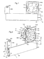
- the trough 1 is here a molding which conventionally comprises a base 10 whose flat bottom 11, intended to be applied against the front face of the recess wall, is bordered longitudinally by lateral wings 12, 13 which rise perpendicular to the bottom 11.
- the base 10 comprises between said lateral wings 12, 13 a longitudinal opening so that it has a U-shaped section.
- the chute 1 further comprises a lid 20 for closing the longitudinal opening of the base 10.
- the cover 20 is said to cover the fact that it has falling edges 21, 22 intended to cover the lateral wings 12, 13 of the base 10.
- the fixing of the cover 20 on the base 10 of the chute 1 is made by snapping a rib 22A which runs longitudinally on the inner face of a falling edge 22 of the cover 20 in a longitudinal groove 12A provided recessed on the corresponding lateral wing 12 of the base 10.
- This electrical box 100 comprises a box body 110 whose internal volume forms a housing adapted to receive at least one electrical equipment mechanism (not shown), and a foot 120, laterally extending the body of the electrical box 110, whose volume An interior communicating with said housing is adapted to receive electrical conductors (not shown) necessary for serving said fitting mechanism.
- the box body 110 comprises a bottom 112, a side wall 113 substantially cylindrical in revolution about an axis X which defines said housing internally, and a front opening 111 provided opposite the bottom 112 for the introduction of the mechanism of electrical equipment (not shown) in said housing of the box body 110.
- the side wall 113 has near the bottom 112 of the inputs 114 of cable ducts and / or electrical conductors (not shown). These entries 114 are closed by knockouts.
- the front opening 111 of the box body 110 is bordered by a flange 115 which is intended to bear on the recess wall, in particular to prevent said electrical box 100 from sinking too much into the recess. embedding.
- This flange 115 comprises at least one arrangement for receiving means (not shown) for injecting glue between said electrical box 100 and the wall in which said electrical box 100 is embedded.
- said flange 115 is formed with the box body 110 of said electrical box 100 which is made by molding a transparent plastic material, but according to an embodiment variant not shown, it is possible for said flange to be an insert on said box body 110.
- the flange 115 is provided with at least one through orifice 118 (here four through holes) adapted to receive said glue injection means.
- the side wall 113 of the box body 110 of the electrical box 100 is provided with conduits 117 for supplying glue which extend along the axis X of said box body 110 to the right of the through holes 118 of the collar 115.
- Each duct 117 for supplying glue is a recessed groove on the external face of said side wall 113.
- each duct 117 for supplying glue extends over the entire height (from the edge of the front opening 111 to the edge of the bottom 112) of the box body 110.
- the box body 110 of the electrical box 100 comprises mechanical attachment means to the wall in which it is recessed. These attachment means are particularly suitable for fixing the electrical box 100 in a hole of a hollow wall such as a cellular partition.
- the side wall 113 has, on its outer face, at least one longitudinal recess 119A (here two diametrically opposite identical recesses) which extends parallel to the X axis from the edge of said front opening 111 to near the bottom 112 of the box body 110 where it opens laterally into a housing 116 for receiving a claw (not shown) constituting said attachment means.
- longitudinal recess 119A here two diametrically opposite identical recesses
- each claw is able to take two positions, namely, on the one hand, a retracted position inside said housing 116 so that it is placed inside the jig of the box body 110 for the engagement of the latter within the hole of the recessed wall considered, and, secondly, a projecting position of the outer face of the wall 113 of the box body 110 for anchoring the box body 110 inside the hole.
- Said actuating means preferably comprise a screw whose threaded body received in the recess 119A cooperates by screwing with the claw.
- the flange 115 of the box body 110 comprises a well 119B for receiving the head of each screw so that said head is accessible on the side of the front opening 111 of the box body 110.
- This well is pierced in its bottom. a passage hole of the threaded body of said screw.
- Each screw, which passes through the flange 115, is fixed in translation and free to rotate about its axis.
- Said means for actuating the claw also comprise a ramp (not visible in the figures) provided on said side wall 113 of the box body 110.
- said flange 115 is surrounded by a detachable square frame 115A.
- This frame 115A is attached punctually to said flange 115 by breakable connections. It bears on the front face of the recess wall when said electrical box 100 is engaged in the recessing hole and is intended to receive in abutment the embellisher plate 300 of the electrical equipment whose mechanism is introduced into the recess. housing of said electrical box.
- the frame 115A eliminates the possible play existing in said trim plate and said embedding wall, this clearance being due to the non-zero thickness of the flange 115 resting on the front face of said embedding wall.
- the box body 110 comprises fixing screw receiving ducts which open on the front in said collar 115.
- the foot 120 is defined by a bottom 120A and two longitudinal walls 121A, 122A, which extend substantially parallel to each other, at a distance from one another, which, in the embodiment shown is less than the width of the inner housing of the box body 110, and, perpendicular to the longitudinal walls 121A, 122A, a transverse end wall 123.
- the electrical box 100 is adapted to be flat, if desired, on any support surface which may be either a floor or a surface belonging for example to one or the other. other amounts of a doorframe.
- the foot 120 has, like the box body 110, opposite the bottom 120A, a front opening 120B which extends over substantially the entire length of said foot 120, so that the interior volume of said foot 120 is at least partially accessible from the front for the passage of cables and / or electrical conductors from the base 10 of the chute 1.
- the interior volume of the leg 120 communicates with the housing of the box body 110 through an opening 124 located in said side wall 113. Moreover, said longitudinal walls 121A, 122A of the leg 120 extend from said side wall 113 according to a direction substantially perpendicular to the axis X of the box body 110.
- the foot comprises two parts 121, 122, namely, a fixed part 121 attached to the box body 110 and a movable part 122 with respect to said fixed part 121.
- the fixed part is here made in one piece with the box body 110 by molding a plastic material.
- the movable portion can be reported by interlocking on said fixed part.
- the movable part comprises interlocking means adapted to cooperate with complementary interlocking means staggered along the length of the fixed part.
- said movable part 122 is a telescopic part which slides relative to said fixed part 121.
- the length of the leg 120 may be shortened or increased to accommodate different widths of trough base 1 so that foot 120 extends the full width of said trough.
- the electric box 100 has a projecting lashing means 130 to the base 10 of the chute 1, arranged to index the position of the box body 110 in said hole relative to that of said base 10 of the chute 1.
- This securing means 130 is located on the front face of said electrical box 100. Here it is located on the front of said foot 120 near the junction between the interior volumes of the foot 120 and the box body 110.
- the securing means comprises a rib 130 which extends transversely to the longitudinal axis of said foot 120 and which is able to engage in a groove 13A which runs on a longitudinal side of said base 10.
- said securing means 130 is made in one piece with the electrical box 100 by molding a plastic material, here a transparent plastic material, but according to a variant not shown can be provided that said securing means is an insert on said electrical box.
- the flange 115 is an autonomous part attached to any electrical box to be embedded in a wall along a chute projecting projecting on said wall, this flange being intended for external border front opening of said electrical box and comprising a lashing means at the base of said chute arranged to index the position of the electrical box in said hole relative to that of said base of the chute.
- the securing means is advantageously a rib located on the front face of said collar.
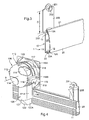
- the electrical box 100 includes a fitting accessory 200 arranged to index the position of a centralizer 31 of a drilling tool 30, adapted to produce in said wall the receiving hole of said electrical box 100, with respect to the position of the base 10 of the chute 1.
- This installation accessory 200 is here in the form of a plate which comprises on the front face a securing means 203 to the base 10 of the chute 1 and a positioning means 201 of the centralizer 31 which are separated from each other. other a distance D equal to the distance D1 between the axis X of the box body 110 of said electrical box 100 of its securing means 130 to the base 10 of the chute 1.
- the securing means of the fitting accessory 200 comprises a rib 203 which extends transversely to the longitudinal axis of said fitting accessory 200 and which is adapted to engage in said groove 13A running on the longitudinal side of said base 10.
- Said positioning means is a through hole 201 which accommodates the centralizer 31.
- This through hole 201 is bordered, on the side of the front face of the fitting accessory 200, with a flange 202 which contributes to maintaining the centralizer 31 in said through hole 201.
- the installation accessory 200 comprises a coating of adhesive material 205 which makes it possible to temporarily fix the installation accessory 200 to the recess wall P to achieve with the aid of the drilling tool 30 the hole T intended to accommodate the electrical box 100.
- the installation accessory 200 is formed with said electrical box 100 by molding a plastic material and is attached thereto by a breakable connection. In this way, the fitting accessory 200 is captive and can be detached from said electrical box 100 to be used.
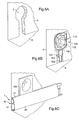
- a hole T is made in said wall P by means of a drilling tool.
- This hole T has a circular portion intended to accommodate the cylindrical box body 110 of the electrical box 100 and a linear portion extending from said circular portion to a bearing surface S, here the floor from which wall P rises.
- This linear part is intended to receive the foot 120 of the electrical box 100.
- the flange 115 of the box body 110 is supported on the front face of the wall P, which makes it possible to prevent the electrical box 100 from sinking too far into said hole T.
- the position of the movable portion 122 of the leg 120 is adjusted relative to the fixed portion 121 so that the transverse end wall 123 of the leg 120 integral with said movable portion 122 rests against the bearing surface S.
- the chute base 1 is connected to said wall P so as to secure said electrical box 100 to the base 10 in order to adjust its position in the hole T with respect to said base 10.
- the trough 1 runs in baseboard on the P wall
- the base 10 of the chute 1 is then fixed on said wall P and the electrical box 100 in its adjusted position in said hole T.
- the fixing of the electrical box 100 can advantageously be achieved by gluing.
- the injection nozzle of a gun or a glue container is then positioned in the corresponding through orifice 118 of collar 115, and the glue contained in said container is injected between lateral wall 113 of the body of box 110 and the wall P.
- the glue flows into said adhesive supply ducts 117 provided on the external face of the side wall 113 of the box body 110 of the electrical box 100 so as to be distributed uniformly in the free space existing between the wall P and the electrical box 100.
- the flange 115 which bears against the front face of the wall P advantageously forms an obstacle which prevents the injected adhesive from rising and overflowing on the front face of said wall P. Thus no cleaning operation of said wall is necessary.
- the transparent material constituting said electrical box 100 allows the installer to control the quantity and distribution of the glue that he injects into the embedding hole.
- the recess wall is a hollow wall
- to fix by gluing said electrical box 100 in a hollow wall can be made (without this being necessary), prior to the injection of glue, a seal between the hollow wall and said electrical box 100 to prevent the glue injected into the mounting hole does not flow into the cells of the latter.
- the installer can prefix the electrical box 100 before bonding with said attachment means that it comprises.
- the installer screws each of the screws to raise each claw along the side wall 113 of the box body 110 of the electrical box 100.
- the claw under the action of the screw, moves in its housing, then cooperates with the corresponding ramp and pivots out of its housing and take the projecting position of the side wall 113 of the box body 110 of the electrical box 100.
- each claw positioned projecting from the side wall 113, rises along it to bear against the rear face of the hollow wall concerned to retain the electrical box 100 within the hole of said hollow front wall it is glued by glue injection through said through orifices 118 of the flange 115.
- the equipment mechanism is reported in the electrical box 100, said gearing mechanism is then connected to the base 10 of the chute 1 and its cover 20 is fixed and fixed on the apparatus mechanism the embellisher plate 300 (here a socket plate) one edge of which perfectly touches the lid 20 of the chute 1.
Landscapes
- Engineering & Computer Science (AREA)
- Architecture (AREA)
- Civil Engineering (AREA)
- Structural Engineering (AREA)
- Connection Or Junction Boxes (AREA)
- Control And Other Processes For Unpacking Of Materials (AREA)
- Electrical Discharge Machining, Electrochemical Machining, And Combined Machining (AREA)
- Cable Accessories (AREA)
- Laying Of Electric Cables Or Lines Outside (AREA)
- Details Of Indoor Wiring (AREA)
Claims (18)
- Anschlussdose (100) zum Einbau in einem Loch in einer Wand entlang einem auf der Wand aufgesetzten Kabelkanal (1), wobei die Anschlussdose ein Gehäuse (110) hat, dessen Innenraum eine Aussparung bildet, die mindestens ein elektrisches Gerät aufnehmen kann, sowie einen Fuß (120), der das Gehäuse (110) seitlich verlängert und dessen mit der Aussparung in Verbindung stehender Innenraum die für die elektrische Versorgung des elektrischen Geräts erforderlichen elektrischen Leiter aufnehmen kann, dadurch gekennzeichnet, dass sie ein hervorstehendes Mittel zum Befestigen (130) am Sockel (10) des Kabelkanals (1) umfasst, um die Position des Gehäuses (110) in diesem Loch in Bezug auf die des Sockels (10) des Kabelkanals zu arretieren.
- Anschlussdose (100) nach Anspruch 1, dadurch gekennzeichnet, dass sich das Mittel zum Befestigen (130) auf der Vorderseite der Anschlussdose befindet.
- Anschlussdose (100) nach einem der Ansprüche 1 oder 2, dadurch gekennzeichnet, dass sich das Mittel zum Befestigen (130) auf der Frontseite des Fußes (120) in der Nähe der Verbindung zwischen den Innenräumen des Fußes (120) und des Gehäuses (110) befindet.
- Anschlussdose (100) nach einem der Ansprüche 1 bis 3, dadurch gekennzeichnet, dass das Mittel zum Befestigen eine Rippe (130) umfasst, die sich quer zur Längsachse des Fußes erstreckt und in eine Rille (13A) eingreifen kann, die auf einer Längsseite des Sockels (10) verläuft.
- Anschlussdose (100) nach einem der Ansprüche 1 bis 4, dadurch gekennzeichnet, dass das Mittel zum Befestigen (130) durch Formgießen eines Kunststoffes aus einem Teil mit dem Gehäuse realisiert wird.
- Anschlussdose (100) nach einem der Ansprüche 1 bis 4, dadurch gekennzeichnet, dass das Mittel zum Befestigen ein auf die Anschlussdose aufgesetztes Teil ist.
- Anschlussdose (100) nach einem der Ansprüche 1 bis 6, dadurch gekennzeichnet, dass der Fuß (120) zwei Abschnitte umfasst, nämlich einen festen, mit dem Gehäuse der Dose (110) verbundenen Abschnitt (121), sowie einen in Bezug zum festen Abschnitt (121) beweglichen Abschnitt (122).
- Anschlussdose (100) nach Anspruch 7, dadurch gekennzeichnet, dass der bewegliche Abschnitt (122) ein teleskopischer Abschnitt ist, der in Bezug zum festen Abschnitt (121) gleitet.
- Anschlussdose (100) nach einem der Ansprüche 1 bis 8, dadurch gekennzeichnet, dass sie ein Zubehör für die Montage (200) umfasst, um die Position einer Zentriervorrichtung (31) eines Bohrwerkzeuges (30), das das Loch für die Aufnahme der Anschlussdose in der Wand bohren kann, in Bezug auf die Position des Kabelkanalsockels zu arretieren, wobei dieses Zubehör für die Montage (200) ein Mittel zum Befestigen (203) am Sockel (10) des Kabelkanals (1) und ein Mittel zum Positionieren (201,202) der Zentriervorrichtung (31) umfasst, die voneinander um die gleiche Distanz (D) beabstandet sind wie die Distanz (D1) zwischen der zur Öffnung der Anschlussdose senkrechten Achse und dem Mittel zum Befestigen (130) am Sockel (10) des Kabelkanals (1).
- Anschlussdose (100) nach Anspruch 9, dadurch gekennzeichnet, dass das Mittel zum Befestigen eine Rippe (203) umfasst, die sich quer zur Längsachse des Zubehörs zum Montieren (200) erstreckt und die in eine Rille (13A) eingreifen kann, die auf einer Längsseite des Sockels (10) verläuft.
- Anschlussdose (100) nach einem der Ansprüche 9 oder 10, dadurch gekennzeichnet, dass das Mittel zum Positionieren eine durchgehende Öffnung (201) ist, die die Zentriervorrichtung aufnimmt.
- Anschlussdose nach einem der Ansprüche 9 bis 11, dadurch gekennzeichnet, dass das Zubehör zum Montieren die Form eines Stegs annimmt, dessen Vorderseite das Mittel zum Befestigen (203) enthält.
- Anschlussdose (100) nach einem der Ansprüche 9 bis 11, dadurch gekennzeichnet, dass das Zubehör für die Montage (200) durch Formgießen eines Kunststoffes zusammen mit der Anschlussdose (100) realisiert wird und mit dieser über eine abtrennbare Verbindung verbunden ist.
- Klammer (115) zum Aufsetzen auf einer Anschlussdose (100), die in ein Loch in einer Wand entlang einem auf der Wand aufgesetzten Kabelkanal (1) eingebaut wird, wobei diese Klammer dazu bestimmt ist, die frontale Öffnung der Anschlussdose (100) außen einzufassen und ein Mittel zum Befestigen (130) am Sockel des Kabelkanals umfasst, mit dem auch die Position der Anschlussdose im Loch in Bezug auf die Position des Kabelkanalsockels arretiert wird.
- Klammer nach Anspruch 14, dadurch gekennzeichnet, dass sich das Mittel zum Befestigen (130) auf der Vorderseite der Klammer (115) befindet.
- Klammer nach einem der Ansprüche 14 oder 15, dadurch gekennzeichnet, dass das Mittel zum Befestigen (130) eine Rippe ist.
- Einbauverfahren in eine Wand der Anschlussdose nach einem der Ansprüche 1 bis 13 oder einer beliebigen Anschlussdose mit einer Klammer nach einem der Ansprüche 14 bis 16, entlang einem auf der Wand (P) aufzusetzenden Kabelkanal, dadurch gekennzeichnet, dass es folgende Schritte umfasst:a) man realisiert mit einem Bohrwerkzeug ein Loch (T) in der Wand (P)b) man ordnet die Anschlussdose (100) im Loch (T) der Wand (P) an,c) man setzt den Kabelkanalsockel (10) so auf die Wand (P) auf, dass die Anschlussdose (100) mit dem Sockel (10) befestigt wird, um ihre Position im Loch (T) in Bezug zum Sockel (10) zu justieren, undc) man fixiert den Kabelkanalsockel (10) an der Wand (P) und die Anschlussdose (100) in der im Loch (T) justierten Position.
- Verfahren nach Anspruch 17 für den Einbau einer Anschlussdose nach Anspruch 9, dadurch gekennzeichnet, dass vor dem Schritt a) folgende Schritte ausgeführt werden:1) man befestigt das Zubehör für die Montage (200) am Sockel (10) des Kabelkanals (1),2) man ordnet den Sockel (10) des Kabelkanals (1) so an der gewünschten Stelle an der Wand an, dass das befestigte Zubehör für die Montage (200) gegen die Wand (P) gedrückt wird,3) man fixiert das Zubehör für die Montage (200) vorübergehend an der Wand (P), und4) man entfernt den Sockel (10) des Kabelkanals (1) von der Wand (P).
Applications Claiming Priority (2)
| Application Number | Priority Date | Filing Date | Title |
|---|---|---|---|
| FR0314226 | 2003-12-04 | ||
| FR0314226A FR2863414B1 (fr) | 2003-12-04 | 2003-12-04 | Boite electrique a encastrer a moyen d'indexation a une goulotte |
Publications (2)
| Publication Number | Publication Date |
|---|---|
| EP1566871A1 EP1566871A1 (de) | 2005-08-24 |
| EP1566871B1 true EP1566871B1 (de) | 2011-03-09 |
Family
ID=34586292
Family Applications (1)
| Application Number | Title | Priority Date | Filing Date |
|---|---|---|---|
| EP04292708A Expired - Lifetime EP1566871B1 (de) | 2003-12-04 | 2004-11-16 | Elektro-Einbaudose mit Indexierungsmitteln für Kabelkanal |
Country Status (5)
| Country | Link |
|---|---|
| EP (1) | EP1566871B1 (de) |
| AT (1) | ATE501536T1 (de) |
| DE (1) | DE602004031709D1 (de) |
| ES (1) | ES2360795T3 (de) |
| FR (1) | FR2863414B1 (de) |
Families Citing this family (2)
| Publication number | Priority date | Publication date | Assignee | Title |
|---|---|---|---|---|
| CN103383484B (zh) * | 2012-05-03 | 2015-04-15 | 泰科电子(上海)有限公司 | 光纤接续盒 |
| FR3039719B1 (fr) * | 2015-07-28 | 2017-12-15 | Legrand France | Ensemble d'appareillages electriques |
Family Cites Families (3)
| Publication number | Priority date | Publication date | Assignee | Title |
|---|---|---|---|---|
| FR2658009B1 (fr) * | 1990-02-02 | 1992-05-22 | Legrand Sa | Boite d'encastrement a prolongement lateral, notamment pour appareil electrique. |
| FR2779876B1 (fr) * | 1998-06-12 | 2000-08-25 | Legrand Sa | Accessoire de derivation pour installation electrique, et installation electrique correspondante |
| ES1050853Y (es) * | 2002-01-04 | 2002-09-16 | Aparellaje Electrico Sl | Adaptador de mecanismos electricos a una canaleta portadora de cables electricos. |
-
2003
- 2003-12-04 FR FR0314226A patent/FR2863414B1/fr not_active Expired - Fee Related
-
2004
- 2004-11-16 ES ES04292708T patent/ES2360795T3/es not_active Expired - Lifetime
- 2004-11-16 AT AT04292708T patent/ATE501536T1/de not_active IP Right Cessation
- 2004-11-16 DE DE602004031709T patent/DE602004031709D1/de not_active Expired - Lifetime
- 2004-11-16 EP EP04292708A patent/EP1566871B1/de not_active Expired - Lifetime
Also Published As
| Publication number | Publication date |
|---|---|
| ES2360795T3 (es) | 2011-06-09 |
| FR2863414B1 (fr) | 2006-02-03 |
| FR2863414A1 (fr) | 2005-06-10 |
| ATE501536T1 (de) | 2011-03-15 |
| DE602004031709D1 (de) | 2011-04-21 |
| EP1566871A1 (de) | 2005-08-24 |
Similar Documents
| Publication | Publication Date | Title |
|---|---|---|
| FR3000309A1 (fr) | Boite electrique d'encastrement a fixation automatique sur une paroi | |
| EP2882056A1 (de) | Rahmen für Einbaumontage einer Elektrodose in einer Wand und Montage eines solchen Rahmens mit einer Elektrodose | |
| EP0844714A1 (de) | Immobilisierungszubehör für ein elektrisches Installationsgerät mit Direktschnappverbindung | |
| EP1094581B1 (de) | Durchführungszubehör für Kabelkanal | |
| EP0813663B1 (de) | Eckverbindungsvorrichtung für eine rinnenförmige leitung und eine abdeckung wie z.b. eine profilleiste, eine sockelleiste oder eine rinne, insbesondere für ein elektrisches bauteil | |
| EP2940815B1 (de) | Dichter elektrischer schaltschrank zum einbau in eine wand | |
| FR2863414A1 (fr) | Boite electrique a encastrer a moyen d'indexation a une goulotte | |
| EP1587197B1 (de) | Einbaudose mit Verbindungszubehör für einen Kanal | |
| EP0440556B1 (de) | Einbaudose mit Seitenverlängerung, insbesondere für elektrisches Gerät | |
| EP1305550B1 (de) | Beleuchtungsträger für einen abgeschlossenen raum, der ein feuchtes medium enthält | |
| EP0267079B1 (de) | Abzweigungszubehör für Verkabelungsrohr | |
| EP0923176B1 (de) | Greifhalter für Einbaudose und entsprechende Einbaudose | |
| FR2810467A1 (fr) | Dispositif de montage d'un appareil electrique sur un conduit de cablage | |
| EP1458074A1 (de) | Zweiteilige Einbaudose für elektrische Geräte | |
| EP0875974B1 (de) | Unterputzdose in einer Wand geringer Dicke für elektrisches Gerät mit einer Leitungsklappeinführung | |
| FR3043853A1 (fr) | Bague de reception d'une boite electrique a encastrer dans une paroi murale | |
| EP1744426B1 (de) | Elektrischer Kasten bestehend aus zwei Elemente die mit einer Zahnstange zusammen befestigt sind | |
| FR3087214A1 (fr) | Boîtier de banche pour la pose de raccord de plomberie | |
| EP0721245A1 (de) | Geräteträger für ein teilweise in einer Leitung versenktes Gehäuse, und Verfahren zu seiner Durchführung | |
| EP2632003B1 (de) | Elektrogerät mit verstärkter Abdichtung | |
| EP1304784B1 (de) | Dose zur Montage entlang einem Kabel- oder Leitungskanal | |
| EP0964495B1 (de) | Unterputzdose mit Körper und Fuss als Doseverlängerung insbesondere für elektrische Geräte | |
| EP0964494B1 (de) | Abzweigungszubehör für Elektroinstallation sowie Elektroinstallation | |
| FR3000869A1 (fr) | Bague de montage d'une boite d'encastrement pour appareillage electrique | |
| EP1396647A1 (de) | Einrastbare Drehriegelvorrichtung |
Legal Events
| Date | Code | Title | Description |
|---|---|---|---|
| PUAI | Public reference made under article 153(3) epc to a published international application that has entered the european phase |
Free format text: ORIGINAL CODE: 0009012 |
|
| AK | Designated contracting states |
Kind code of ref document: A1 Designated state(s): AT BE BG CH CY CZ DE DK EE ES FI FR GB GR HU IE IS IT LI LU MC NL PL PT RO SE SI SK TR |
|
| AX | Request for extension of the european patent |
Extension state: AL HR LT LV MK YU |
|
| 17P | Request for examination filed |
Effective date: 20060105 |
|
| AKX | Designation fees paid |
Designated state(s): AT BE BG CH CY CZ DE DK EE ES FI FR GB GR HU IE IS IT LI LU MC NL PL PT RO SE SI SK TR |
|
| RAP1 | Party data changed (applicant data changed or rights of an application transferred) |
Owner name: LEGRAND FRANCE Owner name: LEGRAND SNC |
|
| GRAP | Despatch of communication of intention to grant a patent |
Free format text: ORIGINAL CODE: EPIDOSNIGR1 |
|
| GRAS | Grant fee paid |
Free format text: ORIGINAL CODE: EPIDOSNIGR3 |
|
| GRAA | (expected) grant |
Free format text: ORIGINAL CODE: 0009210 |
|
| AK | Designated contracting states |
Kind code of ref document: B1 Designated state(s): AT BE BG CH CY CZ DE DK EE ES FI FR GB GR HU IE IS IT LI LU MC NL PL PT RO SE SI SK TR |
|
| REG | Reference to a national code |
Ref country code: GB Ref legal event code: FG4D Free format text: NOT ENGLISH |
|
| REG | Reference to a national code |
Ref country code: CH Ref legal event code: EP |
|
| REG | Reference to a national code |
Ref country code: IE Ref legal event code: FG4D Free format text: LANGUAGE OF EP DOCUMENT: FRENCH |
|
| REF | Corresponds to: |
Ref document number: 602004031709 Country of ref document: DE Date of ref document: 20110421 Kind code of ref document: P |
|
| REG | Reference to a national code |
Ref country code: DE Ref legal event code: R096 Ref document number: 602004031709 Country of ref document: DE Effective date: 20110421 |
|
| REG | Reference to a national code |
Ref country code: ES Ref legal event code: FG2A Ref document number: 2360795 Country of ref document: ES Kind code of ref document: T3 Effective date: 20110609 |
|
| REG | Reference to a national code |
Ref country code: NL Ref legal event code: VDEP Effective date: 20110309 |
|
| PG25 | Lapsed in a contracting state [announced via postgrant information from national office to epo] |
Ref country code: SE Free format text: LAPSE BECAUSE OF FAILURE TO SUBMIT A TRANSLATION OF THE DESCRIPTION OR TO PAY THE FEE WITHIN THE PRESCRIBED TIME-LIMIT Effective date: 20110309 Ref country code: GR Free format text: LAPSE BECAUSE OF FAILURE TO SUBMIT A TRANSLATION OF THE DESCRIPTION OR TO PAY THE FEE WITHIN THE PRESCRIBED TIME-LIMIT Effective date: 20110610 |
|
| PG25 | Lapsed in a contracting state [announced via postgrant information from national office to epo] |
Ref country code: CY Free format text: LAPSE BECAUSE OF FAILURE TO SUBMIT A TRANSLATION OF THE DESCRIPTION OR TO PAY THE FEE WITHIN THE PRESCRIBED TIME-LIMIT Effective date: 20110309 Ref country code: AT Free format text: LAPSE BECAUSE OF FAILURE TO SUBMIT A TRANSLATION OF THE DESCRIPTION OR TO PAY THE FEE WITHIN THE PRESCRIBED TIME-LIMIT Effective date: 20110309 Ref country code: BG Free format text: LAPSE BECAUSE OF FAILURE TO SUBMIT A TRANSLATION OF THE DESCRIPTION OR TO PAY THE FEE WITHIN THE PRESCRIBED TIME-LIMIT Effective date: 20110609 Ref country code: SI Free format text: LAPSE BECAUSE OF FAILURE TO SUBMIT A TRANSLATION OF THE DESCRIPTION OR TO PAY THE FEE WITHIN THE PRESCRIBED TIME-LIMIT Effective date: 20110309 Ref country code: NL Free format text: LAPSE BECAUSE OF FAILURE TO SUBMIT A TRANSLATION OF THE DESCRIPTION OR TO PAY THE FEE WITHIN THE PRESCRIBED TIME-LIMIT Effective date: 20110309 Ref country code: FI Free format text: LAPSE BECAUSE OF FAILURE TO SUBMIT A TRANSLATION OF THE DESCRIPTION OR TO PAY THE FEE WITHIN THE PRESCRIBED TIME-LIMIT Effective date: 20110309 |
|
| REG | Reference to a national code |
Ref country code: IE Ref legal event code: FD4D |
|
| PG25 | Lapsed in a contracting state [announced via postgrant information from national office to epo] |
Ref country code: PT Free format text: LAPSE BECAUSE OF FAILURE TO SUBMIT A TRANSLATION OF THE DESCRIPTION OR TO PAY THE FEE WITHIN THE PRESCRIBED TIME-LIMIT Effective date: 20110711 Ref country code: EE Free format text: LAPSE BECAUSE OF FAILURE TO SUBMIT A TRANSLATION OF THE DESCRIPTION OR TO PAY THE FEE WITHIN THE PRESCRIBED TIME-LIMIT Effective date: 20110309 Ref country code: IE Free format text: LAPSE BECAUSE OF FAILURE TO SUBMIT A TRANSLATION OF THE DESCRIPTION OR TO PAY THE FEE WITHIN THE PRESCRIBED TIME-LIMIT Effective date: 20110309 |
|
| PG25 | Lapsed in a contracting state [announced via postgrant information from national office to epo] |
Ref country code: SK Free format text: LAPSE BECAUSE OF FAILURE TO SUBMIT A TRANSLATION OF THE DESCRIPTION OR TO PAY THE FEE WITHIN THE PRESCRIBED TIME-LIMIT Effective date: 20110309 Ref country code: RO Free format text: LAPSE BECAUSE OF FAILURE TO SUBMIT A TRANSLATION OF THE DESCRIPTION OR TO PAY THE FEE WITHIN THE PRESCRIBED TIME-LIMIT Effective date: 20110309 Ref country code: IS Free format text: LAPSE BECAUSE OF FAILURE TO SUBMIT A TRANSLATION OF THE DESCRIPTION OR TO PAY THE FEE WITHIN THE PRESCRIBED TIME-LIMIT Effective date: 20110709 Ref country code: CZ Free format text: LAPSE BECAUSE OF FAILURE TO SUBMIT A TRANSLATION OF THE DESCRIPTION OR TO PAY THE FEE WITHIN THE PRESCRIBED TIME-LIMIT Effective date: 20110309 |
|
| PLBE | No opposition filed within time limit |
Free format text: ORIGINAL CODE: 0009261 |
|
| STAA | Information on the status of an ep patent application or granted ep patent |
Free format text: STATUS: NO OPPOSITION FILED WITHIN TIME LIMIT |
|
| 26N | No opposition filed |
Effective date: 20111212 |
|
| PG25 | Lapsed in a contracting state [announced via postgrant information from national office to epo] |
Ref country code: DK Free format text: LAPSE BECAUSE OF FAILURE TO SUBMIT A TRANSLATION OF THE DESCRIPTION OR TO PAY THE FEE WITHIN THE PRESCRIBED TIME-LIMIT Effective date: 20110309 Ref country code: PL Free format text: LAPSE BECAUSE OF FAILURE TO SUBMIT A TRANSLATION OF THE DESCRIPTION OR TO PAY THE FEE WITHIN THE PRESCRIBED TIME-LIMIT Effective date: 20110309 |
|
| REG | Reference to a national code |
Ref country code: DE Ref legal event code: R097 Ref document number: 602004031709 Country of ref document: DE Effective date: 20111212 |
|
| BERE | Be: lapsed |
Owner name: LEGRAND SNC Effective date: 20111130 Owner name: LEGRAND FRANCE Effective date: 20111130 |
|
| PG25 | Lapsed in a contracting state [announced via postgrant information from national office to epo] |
Ref country code: MC Free format text: LAPSE BECAUSE OF NON-PAYMENT OF DUE FEES Effective date: 20111130 |
|
| REG | Reference to a national code |
Ref country code: CH Ref legal event code: PL |
|
| GBPC | Gb: european patent ceased through non-payment of renewal fee |
Effective date: 20111116 |
|
| PG25 | Lapsed in a contracting state [announced via postgrant information from national office to epo] |
Ref country code: LI Free format text: LAPSE BECAUSE OF NON-PAYMENT OF DUE FEES Effective date: 20111130 Ref country code: CH Free format text: LAPSE BECAUSE OF NON-PAYMENT OF DUE FEES Effective date: 20111130 |
|
| PG25 | Lapsed in a contracting state [announced via postgrant information from national office to epo] |
Ref country code: BE Free format text: LAPSE BECAUSE OF NON-PAYMENT OF DUE FEES Effective date: 20111130 |
|
| PG25 | Lapsed in a contracting state [announced via postgrant information from national office to epo] |
Ref country code: GB Free format text: LAPSE BECAUSE OF NON-PAYMENT OF DUE FEES Effective date: 20111116 |
|
| PG25 | Lapsed in a contracting state [announced via postgrant information from national office to epo] |
Ref country code: LU Free format text: LAPSE BECAUSE OF NON-PAYMENT OF DUE FEES Effective date: 20111116 |
|
| PG25 | Lapsed in a contracting state [announced via postgrant information from national office to epo] |
Ref country code: TR Free format text: LAPSE BECAUSE OF FAILURE TO SUBMIT A TRANSLATION OF THE DESCRIPTION OR TO PAY THE FEE WITHIN THE PRESCRIBED TIME-LIMIT Effective date: 20110309 |
|
| PG25 | Lapsed in a contracting state [announced via postgrant information from national office to epo] |
Ref country code: HU Free format text: LAPSE BECAUSE OF FAILURE TO SUBMIT A TRANSLATION OF THE DESCRIPTION OR TO PAY THE FEE WITHIN THE PRESCRIBED TIME-LIMIT Effective date: 20110309 |
|
| REG | Reference to a national code |
Ref country code: FR Ref legal event code: PLFP Year of fee payment: 12 |
|
| REG | Reference to a national code |
Ref country code: FR Ref legal event code: PLFP Year of fee payment: 13 |
|
| REG | Reference to a national code |
Ref country code: FR Ref legal event code: PLFP Year of fee payment: 14 |
|
| PGFP | Annual fee paid to national office [announced via postgrant information from national office to epo] |
Ref country code: ES Payment date: 20191202 Year of fee payment: 16 Ref country code: IT Payment date: 20191120 Year of fee payment: 16 |
|
| PGFP | Annual fee paid to national office [announced via postgrant information from national office to epo] |
Ref country code: DE Payment date: 20200131 Year of fee payment: 16 |
|
| REG | Reference to a national code |
Ref country code: DE Ref legal event code: R119 Ref document number: 602004031709 Country of ref document: DE |
|
| PG25 | Lapsed in a contracting state [announced via postgrant information from national office to epo] |
Ref country code: IT Free format text: LAPSE BECAUSE OF NON-PAYMENT OF DUE FEES Effective date: 20201116 |
|
| PG25 | Lapsed in a contracting state [announced via postgrant information from national office to epo] |
Ref country code: DE Free format text: LAPSE BECAUSE OF NON-PAYMENT OF DUE FEES Effective date: 20210601 |
|
| REG | Reference to a national code |
Ref country code: ES Ref legal event code: FD2A Effective date: 20220202 |
|
| PG25 | Lapsed in a contracting state [announced via postgrant information from national office to epo] |
Ref country code: ES Free format text: LAPSE BECAUSE OF NON-PAYMENT OF DUE FEES Effective date: 20201117 |
|
| PGFP | Annual fee paid to national office [announced via postgrant information from national office to epo] |
Ref country code: FR Payment date: 20231019 Year of fee payment: 20 |