EP1566826A1 - Partikelquelle mit wählbarer Strahlstrom und Energiespreizung - Google Patents
Partikelquelle mit wählbarer Strahlstrom und Energiespreizung Download PDFInfo
- Publication number
- EP1566826A1 EP1566826A1 EP05075340A EP05075340A EP1566826A1 EP 1566826 A1 EP1566826 A1 EP 1566826A1 EP 05075340 A EP05075340 A EP 05075340A EP 05075340 A EP05075340 A EP 05075340A EP 1566826 A1 EP1566826 A1 EP 1566826A1
- Authority
- EP
- European Patent Office
- Prior art keywords
- particle
- lens
- diaphragm
- energy
- image
- Prior art date
- Legal status (The legal status is an assumption and is not a legal conclusion. Google has not performed a legal analysis and makes no representation as to the accuracy of the status listed.)
- Granted
Links
Images
Classifications
-
- H—ELECTRICITY
- H01—ELECTRIC ELEMENTS
- H01J—ELECTRIC DISCHARGE TUBES OR DISCHARGE LAMPS
- H01J37/00—Discharge tubes with provision for introducing objects or material to be exposed to the discharge, e.g. for the purpose of examination or processing thereof
- H01J37/02—Details
- H01J37/04—Arrangements of electrodes and associated parts for generating or controlling the discharge, e.g. electron-optical arrangement or ion-optical arrangement
- H01J37/05—Electron or ion-optical arrangements for separating electrons or ions according to their energy or mass
-
- H—ELECTRICITY
- H01—ELECTRIC ELEMENTS
- H01J—ELECTRIC DISCHARGE TUBES OR DISCHARGE LAMPS
- H01J37/00—Discharge tubes with provision for introducing objects or material to be exposed to the discharge, e.g. for the purpose of examination or processing thereof
- H01J37/02—Details
- H01J37/04—Arrangements of electrodes and associated parts for generating or controlling the discharge, e.g. electron-optical arrangement or ion-optical arrangement
- H01J37/09—Diaphragms; Shields associated with electron or ion-optical arrangements; Compensation of disturbing fields
-
- H—ELECTRICITY
- H01—ELECTRIC ELEMENTS
- H01J—ELECTRIC DISCHARGE TUBES OR DISCHARGE LAMPS
- H01J37/00—Discharge tubes with provision for introducing objects or material to be exposed to the discharge, e.g. for the purpose of examination or processing thereof
- H01J37/02—Details
- H01J37/04—Arrangements of electrodes and associated parts for generating or controlling the discharge, e.g. electron-optical arrangement or ion-optical arrangement
- H01J37/153—Electron-optical or ion-optical arrangements for the correction of image defects, e.g. stigmators
-
- H—ELECTRICITY
- H01—ELECTRIC ELEMENTS
- H01J—ELECTRIC DISCHARGE TUBES OR DISCHARGE LAMPS
- H01J37/00—Discharge tubes with provision for introducing objects or material to be exposed to the discharge, e.g. for the purpose of examination or processing thereof
- H01J37/26—Electron or ion microscopes; Electron or ion diffraction tubes
Definitions
- the invention relates to a particle-optical apparatus equipped with a particle source, which particle source is embodied to generate at least one beam of electrically charged particles and which particle source is provided with:
- the particle beam described therein has the form of an electron source, can be used in, for example, electron microscopes, and serves to provide an electron beam with a small energy spread.
- a small energy spread of the electron beam is desirable, because the employed electron-optical lenses will then cause a smaller chromatic aberration, as a result of which a higher resolution is obtained.
- Chromatic aberration is caused by the fact that, in general, the lens has different optical powers for particles with different energies.
- a lens electrostatic or magnetic
- Chromatic aberration is proportional to the energy spread of the particles in the beam. Lower energy spread thus leads to less chromatic aberration.
- an electron beam generated by an electron-emitting surface is focused by a lens with a beam-limiting diaphragm in such a manner that the electron-emitting surface is imaged onto the beam-limiting surface. Between the lens and the image, the electron beam is deflected by a first deflection unit.
- the image formed by the lens is a dispersion line, which is a collection of point foci of particles with different energies, whereby electrons with a given energy will have a corresponding position on the dispersion line.
- the passed electron beam will have a reduced energy spread, since, in the passed portion, only electrons with a certain interval of the original energy spectrum are present.
- the beam is subsequently deflected back again by a second deflection unit, such that the passed beam extends along the direction of the beam before it was deflected by the first deflection unit.
- a second deflection unit it is also possible to cancel the energy dispersion of the beam caused by the first deflection unit.
- the known particle source is a relatively extensive construction.
- the invention aims to provide a more compact construction.
- the particle source according to the invention is characterized in that the beam-limiting diaphragm is embodied in such a way that said beam is a beam that goes through the lens eccentrically.
- the invention is founded upon the insight that it is possible to attain the desired energy dispersion by employing a beam that does not go through the central portion of the lens, but through a portion of the lens that is eccentrically located.
- the lens does not image a point-like object as a round image, which would be the case if the beam were to go through the middle of the lens, but instead as a dispersion line.
- an energy-selecting diaphragm that only allows a portion of the dispersion line to pass, the energy spread of the passed beam will be reduced with respect to the energy spread originally present in the beam.
- the image formed by the lens is a dispersion line, whereby a portion of this dispersion line is allowed to pass by the energy-selecting diaphragm.
- the energy-selecting diaphragm By giving the energy-selecting diaphragm a size in the dispersion direction that, by approximation, is equal to the width of the dispersion line, the passed beam will emerge from an apparently square image.
- This apparent image will then serve as an object for any subsequent optical elements.
- a round form is normally used as an object for subsequent optical elements, a square form is a sufficient approximation of the more usual round object form.
- the image made with the aid of the eccentric beam is formed outside the optical axis. This is caused by the spherical aberration of the lens, which characterizes itself in that, for a beam that goes through the lens far from the middle of the lens, the lens has a greater optical power than for a beam that goes through the central portion of the lens. Because the image of the particle-emitting surface is formed outside the optical axis of the lens, the energy-selecting diaphragm will therefore also not have to be placed on the axis.
- the beam-limiting diaphragm can be placed before, in, or behind the lens. That the eccentric beam may not yet be limited as such when traversing the lens is not essential - it is only essential that the particles that eventually form the eccentric beam go through an eccentrically located portion of the lens.
- the beam-limiting diaphragm is also embodied to allow a beam going through the middle of the lens to pass.
- a particle source in, for example, an electron microscope, there is often a need for a beam whose properties can be selected, e.g. in one observation situation, a beam with a relatively large current without the need for energy reduction, and, in another observation situation, a beam with reduced energy spread without the need for a large current. It is then advantageous if the particle source can generate each of both types of beam according to need.
- a central beam i.e. a beam through the middle of the lens
- the relatively large current is achieved by choosing the diaphragm opening of the beam-limiting diaphragm in the case of this central beam to be larger than the diaphragm opening of the beam-limiting diaphragm in the case of the eccentric beam. Because, of course, a larger diameter of the diaphragm opening implies a larger opening angle of the beam and, therefore, a larger current.
- the particle source according to the invention is provided with a deflection unit, which deflection unit is embodied to deflect one of the beams of electrically charged particles toward an optical axis, in such a manner than this beam further propagates about the optical axis.
- the beams may comprise a central beam and one or more eccentric beams. This can be achieved by applying both several beam-limiting diaphragms and several energy-selecting diaphragms.
- the desired differences in current are achieved by choosing the diameters of the diaphragm openings in the beam-limiting diaphragm to be different, whereas the differences in energy spread can be attained by choosing the diameters of the diaphragm openings in the energy-selecting diaphragm to be different.
- one of the beams is selected. It is desired to manipulate the selected beam in such a manner that this is available about the optical axis for subsequent optical elements that are known per se. This can be achieved by placing a deflection unit in the vicinity of the energy-selecting diaphragm. The selected beam is deflected by the deflection unit toward the optical axis, whereby the other, non-selected beams are not brought into a location about the optical axis. These non-selected beams can be blocked by diaphragms placed behind the deflection unit.
- the deflection unit and lens may be embodied to be electrostatic or magnetic.
- a purely electrostatic embodiment is advantageous when the particle source is an ion source, seeing as it is easier to focus and deflect ions with electric fields than with magnetic fields.
- electrostatic lenses generally cause greater chromatic aberration than magnetic lenses, which in this case means that the (desired) energy dispersion of an electrostatically embodied lens is greater than that of a magnetically embodied lens.
- the particle-emitting surface has the form of several, non-juxtaposed, particle-emitting constituent surfaces.
- This embodiment is advantageous because it is possible herewith to form beams that go through the lens at a position so far from the axis that the eccentric diaphragm opening can no longer be illuminated by a particle-emitting surface placed on the axis. This is because, in general, particle-emitting surfaces only emit particles within a limited opening angle.
- the beams of electrons going through the beam-limiting diaphragm should be essentially parallel beams. This can be achieved by placing an assistive lens in the vicinity of each of the particle-emitting constituent surfaces in such a manner that the particle-emitting constituent surface is located in a focal plane of this assistive lens.
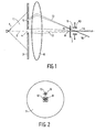
- FIG. 1 schematically shows, in cross-section, a particle source according to the invention.
- a particle-emitting surface such as the electron-emitting surface 1 of a field emission source of electrons, is located on an optical axis 2.
- the beam of electrons 11 emergent from the electron-emitting surface 1 is sub-divided by a diaphragm 3 - containing beam-limiting diaphragm openings in the form of round holes 4 and 5 - into a central beam 12 and an eccentric beam 13. Both beams 12 and 13 are focused by a lens 6 placed on the optical axis 2.
- the electron-emitting surface 1 is imaged by the lens 6, so as to form image 14 via beam 12 and to form image 15 via beam 13.
- the energy-selecting diaphragm opening 9 is located in a diaphragm 7, in which diaphragm 7 a cut-out 8 is also made so as to allow the central beam 12 to pass.
- a deflection unit 10 is placed, which deflects one of the beams (12, 13) about the optical axis 2.
- the electron-emitting surface 1 emits electrons into the beam 11.
- This beam 11 illuminates both the diaphragm opening 4, which is located centrally about the optical axis 2, and the eccentrically located diaphragm opening 5.
- the diaphragm openings 4 and 5 are embodied as round cut-outs in diaphragm 3. In the case of a field emission source, this diaphragm 3 can also serve as an extraction electrode, whereby a voltage difference is applied between the diaphragm 3 and the electron-emitting surface 1.
- the size of the diaphragm openings 4 and 5 determines the current in the beams 12 and 13.
- the eccentricity of the diaphragm opening 5 determines the energy dispersion of the eccentric beam 13.
- the central beam 12 formed by the diaphragm opening 4 is focused by the lens 6, located about the optical axis 2, whereby an image 14 of the electron-emitting surface 1 is formed.
- the eccentric beam 13 is focused, whereby an image 15 (the dispersion line) of the electron-emitting surface is formed.
- Figure 2 shows an elevation of the diaphragm 7, in which diaphragm openings (8, 9) have been cut out so as to allow the central beam 12 and the eccentric beam 13 to pass.
- Figure 2 shows an elevation of diaphragm 7, i.e. what the diaphragm looks like from the side of the source.
- the central beam 12 - located about the optical axis - traverses the diaphragm opening 8 formed by a cut-out in the diaphragm 7.
- the lens 6 focuses the eccentric beam 13, whereby an image 15 of the electron-emitting surface 1 is formed on the diaphragm 7.
- the image 15 of the electron emitting surface 1 is stretched out in the radial direction into a dispersion line.
- electrons with a higher-than-nominal energy will be located further from the optical axis 2 than electrons with a lower-than-nominal energy, because the lens 6 demonstrates a less potent refractive effect for electrons with a high energy than it does for electrons with a low energy.
- the passed beam 16 will have a smaller energy spread than the beam 13 incident upon the diaphragm 7. This is achieved by endowing the diaphragm opening 9 with a dimension in the radial direction that is smaller than the length of the image 15 in the radial direction.
- the various images formed of the electron source have a form that is approximately round.
- a line-like image of the electron source can cause artifacts.
- the width of the image 15 in the tangential direction is equal to the (apparent) size of the electron-emitting surface 1 multiplied by the magnification of the lens 6, it is advantageous if the image 15 of the electron-emitting surface 1 as formed by the lens 6 is an enlarged image.
- the diaphragm opening 9 allow the portion of the image 15 with the highest electron density to pass, seeing as this will result in the highest current in the passed beam 16. It is therefore desired that the image 15 be movable over the diaphragm opening 9, for example with the aid of a deflection unit positioned on the source side of diaphragm 7.
- An attractive embodiment is to combine the deflection unit, which is used to move the beam 13 over the diaphragm opening 9, with a stigmator unit.
- a deflection unit to move the beam 15 over the diaphragm opening 9
- other methods can also be used, for example mechanically displacing the electron-emitting surface 1, the lens 6 or the diaphragm 7, or mildly defocusing the lens 6.
- the point foci that together form the dispersion line at the location of the image 15 are also afflicted with further errors, such as coma, diffraction, etc.
- further errors such as coma, diffraction, etc.
- the beams 12 and 16 that are allowed to pass by the diaphragm 7 can, for example, be focused on a sample that is to be analyzed, using techniques known per se. It is thereby generally of importance that the beam that is focused on the sample be centered about the optical axis 2. This is achieved by the deflection unit 10, which, by means of suitable excitation, can deflect either the beam 16 or the beam 12 about the optical axis 2.
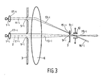
- Figure 3 shows a particle source according to the invention, whereby the particle-emitting surface assumes the form of several, non-juxtaposed, particle-emitting constituent surfaces.
- Figure 3 shows a number N of particle-emitting constituent surfaces 1-1,...,1-N, which are generally indicated by 1-i.
- These particle-emitting constituent surfaces 1-i e.g. in the form of discrete, electron-emitting field emitters, each produces its own beam of electrons 11-i.
- Each of these beams 11-i is limited by its own beam-limiting diaphragm opening 5-i.
- This embodiment is advantageous in that it provides the possibility of forming beams 11-i that go through the lens 6 at a location so far from the axis 2 that the eccentric diaphragm openings 5-i can no longer be illuminated by a particle-emitting surface placed on the axis 2. This is because particle-emitting surfaces generally emit particles within a limited opening angle.
- the beams of electrons 11-i incident upon the lens 6 should be essentially parallel beams. This can be achieved by placing an assistive lens 17-i in the vicinity of each of the electron-emitting constituent surfaces 1-i, in such a manner that the electron-emitting constituent surface 1-i is located in a focal plane of this assistive lens 17-i.
Landscapes
- Chemical & Material Sciences (AREA)
- Analytical Chemistry (AREA)
- Analysing Materials By The Use Of Radiation (AREA)
- Electron Sources, Ion Sources (AREA)
Applications Claiming Priority (2)
| Application Number | Priority Date | Filing Date | Title |
|---|---|---|---|
| NL1025500 | 2004-02-17 | ||
| NL1025500A NL1025500C2 (nl) | 2004-02-17 | 2004-02-17 | Deeltjesbron met selecteerbare bundelstroom en energiespreiding. |
Publications (2)
| Publication Number | Publication Date |
|---|---|
| EP1566826A1 true EP1566826A1 (de) | 2005-08-24 |
| EP1566826B1 EP1566826B1 (de) | 2009-01-14 |
Family
ID=34709387
Family Applications (1)
| Application Number | Title | Priority Date | Filing Date |
|---|---|---|---|
| EP05075340A Expired - Lifetime EP1566826B1 (de) | 2004-02-17 | 2005-02-11 | Teilchenquelle mit wählbarem Strahlstrom und wählbarer Energiestreuung |
Country Status (6)
| Country | Link |
|---|---|
| US (1) | US7034315B2 (de) |
| EP (1) | EP1566826B1 (de) |
| JP (1) | JP4749734B2 (de) |
| CN (1) | CN1658331B (de) |
| DE (1) | DE602005012325D1 (de) |
| NL (1) | NL1025500C2 (de) |
Families Citing this family (28)
| Publication number | Priority date | Publication date | Assignee | Title |
|---|---|---|---|---|
| EP1783811A3 (de) * | 2005-11-02 | 2008-02-27 | FEI Company | Korrektor zur Korrektion von chromatischen Aberrationen in einem korpuskularoptiachen Apparat |
| JP2007335385A (ja) * | 2006-06-15 | 2007-12-27 | Sadao Nomura | 収差補正荷電粒子ビーム発生装置 |
| JP4920370B2 (ja) * | 2006-10-30 | 2012-04-18 | 株式会社日立製作所 | 透過型電子顕微鏡の情報伝達限界測定法およびこの測定法が適用された透過型電子顕微鏡 |
| EP2128885A1 (de) | 2008-05-26 | 2009-12-02 | FEI Company | Quelle für geladene Teilchen mit integriertem Energiefilter |
| EP2226830B1 (de) | 2009-03-06 | 2014-01-08 | FEI Company | Berarbeitung mit einem geladenen Teilchenstrahl |
| EP2402475A1 (de) | 2010-06-30 | 2012-01-04 | Fei Company | Strahleninduzierte Ablagerung bei kryogenischen Temperaturen |
| EP2453461A1 (de) | 2010-11-10 | 2012-05-16 | FEI Company | Quelle für geladene Teilchen mit integriertem elektrostatischen Energiefilter |
| EP2511936B1 (de) | 2011-04-13 | 2013-10-02 | Fei Company | Verzerrungsfreie Stigmation eines TEM |
| US8592761B2 (en) | 2011-05-19 | 2013-11-26 | Hermes Microvision Inc. | Monochromator for charged particle beam apparatus |
| US8274046B1 (en) | 2011-05-19 | 2012-09-25 | Hermes Microvision Inc. | Monochromator for charged particle beam apparatus |
| US9111715B2 (en) | 2011-11-08 | 2015-08-18 | Fei Company | Charged particle energy filter |
| CN103826380B (zh) * | 2014-03-13 | 2016-10-26 | 北京大学 | 一种离子输运装置 |
| KR101633978B1 (ko) * | 2014-06-20 | 2016-06-28 | 한국표준과학연구원 | 모노크로메이터 및 이를 구비한 하전입자빔 장치 |
| US9767984B2 (en) | 2014-09-30 | 2017-09-19 | Fei Company | Chicane blanker assemblies for charged particle beam systems and methods of using the same |
| CN104678543A (zh) * | 2014-12-26 | 2015-06-03 | 中国科学院苏州生物医学工程技术研究所 | 基于非相干光源的光镊显微镜 |
| CN104772460B (zh) * | 2015-04-17 | 2017-01-11 | 华中科技大学 | 一种离子团束3d打印装置及方法 |
| US9905391B2 (en) * | 2015-04-29 | 2018-02-27 | Kla-Tencor Corporation | System and method for imaging a sample with an electron beam with a filtered energy spread |
| CN106290168A (zh) * | 2015-05-18 | 2017-01-04 | 深圳迈瑞生物医疗电子股份有限公司 | 光检测单元、使用该光检测单元的液相色谱分析装置及液相色谱分析方法 |
| JP2017020106A (ja) | 2015-07-02 | 2017-01-26 | エフ・イ−・アイ・カンパニー | 高スループット・パターン形成のための適応ビーム電流 |
| DE102015011070A1 (de) * | 2015-08-27 | 2017-03-02 | Forschungszentrum Jülich GmbH | Vorrichtung zur Korrektur des Längsfehlers der chromatischen Aberration von Strahlung massebehafteter Teilchen |
| EP3203493B1 (de) | 2016-02-02 | 2018-10-03 | FEI Company | Ladungsträger-mikroskop mit astigmatismuskompensation und energieauswahl |
| CN106861056B (zh) * | 2017-01-13 | 2019-05-14 | 北京大学 | 扇形磁铁选能优化与质子医疗能谱调控装置及其调控方法 |
| US10410827B2 (en) | 2017-05-03 | 2019-09-10 | Fei Company | Gun lens design in a charged particle microscope |
| DE102017208005B3 (de) | 2017-05-11 | 2018-08-16 | Carl Zeiss Microscopy Gmbh | Teilchenquelle zur Erzeugung eines Teilchenstrahls und teilchenoptische Vorrichtung |
| EP4002420A1 (de) * | 2020-11-12 | 2022-05-25 | FEI Company | Verfahren zur bestimmung der energiebreite eines geladenen teilchenstrahls |
| DE102021122388A1 (de) * | 2021-08-30 | 2023-03-02 | Carl Zeiss Microscopy Gmbh | Teilchenstrahlsäule |
| US11804357B2 (en) | 2021-09-30 | 2023-10-31 | Fei Company | Electron optical module for providing an off-axial electron beam with a tunable coma |
| US20250157779A1 (en) | 2023-11-10 | 2025-05-15 | Fei Company | Minimization of energy spread in focused ion beam (fib) systems |
Citations (2)
| Publication number | Priority date | Publication date | Assignee | Title |
|---|---|---|---|---|
| EP0500179A1 (de) * | 1991-02-20 | 1992-08-26 | Koninklijke Philips Electronics N.V. | Ladungspartikelbündelanordnung |
| EP1150327A1 (de) * | 2000-04-27 | 2001-10-31 | ICT Integrated Circuit Testing GmbH | Mehrstrahl Ladungsträgerstrahlvorrichtung |
Family Cites Families (3)
| Publication number | Priority date | Publication date | Assignee | Title |
|---|---|---|---|---|
| US3374346A (en) * | 1964-07-15 | 1968-03-19 | Hitachi Ltd | Spectroscopic electron microscope wherein a specimen is irradiated with x-rays and the electrons emitted are energy analyzed |
| NL7004207A (de) * | 1969-07-30 | 1971-02-02 | ||
| GB1416043A (en) * | 1972-01-28 | 1975-12-03 | Nasa | Electron microscope aperture system |
-
2004
- 2004-02-17 NL NL1025500A patent/NL1025500C2/nl not_active IP Right Cessation
-
2005
- 2005-02-11 EP EP05075340A patent/EP1566826B1/de not_active Expired - Lifetime
- 2005-02-11 DE DE602005012325T patent/DE602005012325D1/de not_active Expired - Lifetime
- 2005-02-15 US US11/058,695 patent/US7034315B2/en not_active Expired - Lifetime
- 2005-02-16 JP JP2005039607A patent/JP4749734B2/ja not_active Expired - Lifetime
- 2005-02-16 CN CN200510051944.2A patent/CN1658331B/zh not_active Expired - Lifetime
Patent Citations (2)
| Publication number | Priority date | Publication date | Assignee | Title |
|---|---|---|---|---|
| EP0500179A1 (de) * | 1991-02-20 | 1992-08-26 | Koninklijke Philips Electronics N.V. | Ladungspartikelbündelanordnung |
| EP1150327A1 (de) * | 2000-04-27 | 2001-10-31 | ICT Integrated Circuit Testing GmbH | Mehrstrahl Ladungsträgerstrahlvorrichtung |
Also Published As
| Publication number | Publication date |
|---|---|
| CN1658331B (zh) | 2012-03-21 |
| JP4749734B2 (ja) | 2011-08-17 |
| US20050178982A1 (en) | 2005-08-18 |
| US7034315B2 (en) | 2006-04-25 |
| DE602005012325D1 (de) | 2009-03-05 |
| CN1658331A (zh) | 2005-08-24 |
| NL1025500C2 (nl) | 2005-08-19 |
| JP2005235767A (ja) | 2005-09-02 |
| EP1566826B1 (de) | 2009-01-14 |
Similar Documents
| Publication | Publication Date | Title |
|---|---|---|
| EP1566826B1 (de) | Teilchenquelle mit wählbarem Strahlstrom und wählbarer Energiestreuung | |
| JP5160499B2 (ja) | エネルギーフィルタが一体化された荷電粒子源 | |
| JP4368381B2 (ja) | 荷電粒子ビーム系用の荷電粒子ビームエネルギー幅低減系 | |
| EP2128887B1 (de) | TEM mit Aberrationskorrektor und Phasenplatte | |
| US6218664B1 (en) | SEM provided with an electrostatic objective and an electrical scanning device | |
| US5146090A (en) | Particle beam apparatus having an immersion lens arranged in an intermediate image of the beam | |
| US8158939B2 (en) | High resolution gas field ion column | |
| JP5518128B2 (ja) | 荷電粒子ビーム装置用モノクロメータ及びこれを用いた電子装置 | |
| JP6341680B2 (ja) | 集束イオン・ビームの低kV強化 | |
| JPS6213789B2 (de) | ||
| JP2002532844A (ja) | オージェ電子の検出を含む粒子光学装置 | |
| JP4823995B2 (ja) | 収差補正型質量分離装置 | |
| EP1049131B1 (de) | Teilchenstrahlgerät zur schrägen Beobachtung einer Probe | |
| JP4357530B2 (ja) | 荷電粒子ビーム系用の2段式荷電粒子ビームエネルギー幅低減系 | |
| JP2024023157A (ja) | Sem用簡易球面収差補正器 | |
| JP4343951B2 (ja) | 荷電粒子ビーム系用の単段式荷電粒子ビームエネルギー幅低減系 | |
| JP3790646B2 (ja) | 低エネルギー反射電子顕微鏡 | |
| JP2000277049A (ja) | カソードレンズ | |
| JP4283843B2 (ja) | 幾何収差と空間電荷効果を低減した写像型電子顕微鏡 |
Legal Events
| Date | Code | Title | Description |
|---|---|---|---|
| PUAI | Public reference made under article 153(3) epc to a published international application that has entered the european phase |
Free format text: ORIGINAL CODE: 0009012 |
|
| 17P | Request for examination filed |
Effective date: 20050211 |
|
| AK | Designated contracting states |
Kind code of ref document: A1 Designated state(s): AT BE BG CH CY CZ DE DK EE ES FI FR GB GR HU IE IS IT LI LT LU MC NL PL PT RO SE SI SK TR |
|
| AX | Request for extension of the european patent |
Extension state: AL BA HR LV MK YU |
|
| AKX | Designation fees paid |
Designated state(s): DE FR GB |
|
| 17Q | First examination report despatched |
Effective date: 20071004 |
|
| GRAP | Despatch of communication of intention to grant a patent |
Free format text: ORIGINAL CODE: EPIDOSNIGR1 |
|
| GRAS | Grant fee paid |
Free format text: ORIGINAL CODE: EPIDOSNIGR3 |
|
| GRAA | (expected) grant |
Free format text: ORIGINAL CODE: 0009210 |
|
| AK | Designated contracting states |
Kind code of ref document: B1 Designated state(s): DE FR GB |
|
| REG | Reference to a national code |
Ref country code: GB Ref legal event code: FG4D |
|
| REF | Corresponds to: |
Ref document number: 602005012325 Country of ref document: DE Date of ref document: 20090305 Kind code of ref document: P |
|
| PLBE | No opposition filed within time limit |
Free format text: ORIGINAL CODE: 0009261 |
|
| STAA | Information on the status of an ep patent application or granted ep patent |
Free format text: STATUS: NO OPPOSITION FILED WITHIN TIME LIMIT |
|
| 26N | No opposition filed |
Effective date: 20091015 |
|
| REG | Reference to a national code |
Ref country code: FR Ref legal event code: PLFP Year of fee payment: 12 |
|
| REG | Reference to a national code |
Ref country code: FR Ref legal event code: PLFP Year of fee payment: 13 |
|
| REG | Reference to a national code |
Ref country code: FR Ref legal event code: PLFP Year of fee payment: 14 |
|
| PGFP | Annual fee paid to national office [announced via postgrant information from national office to epo] |
Ref country code: DE Payment date: 20240206 Year of fee payment: 20 Ref country code: GB Payment date: 20240208 Year of fee payment: 20 |
|
| PGFP | Annual fee paid to national office [announced via postgrant information from national office to epo] |
Ref country code: FR Payment date: 20240228 Year of fee payment: 20 |
|
| REG | Reference to a national code |
Ref country code: DE Ref legal event code: R071 Ref document number: 602005012325 Country of ref document: DE |
|
| REG | Reference to a national code |
Ref country code: GB Ref legal event code: PE20 Expiry date: 20250210 |
|
| PG25 | Lapsed in a contracting state [announced via postgrant information from national office to epo] |
Ref country code: GB Free format text: LAPSE BECAUSE OF EXPIRATION OF PROTECTION Effective date: 20250210 |