EP1566804A1 - Data recording and reproducing device, and data recording and reproducing method - Google Patents
Data recording and reproducing device, and data recording and reproducing method Download PDFInfo
- Publication number
- EP1566804A1 EP1566804A1 EP02785986A EP02785986A EP1566804A1 EP 1566804 A1 EP1566804 A1 EP 1566804A1 EP 02785986 A EP02785986 A EP 02785986A EP 02785986 A EP02785986 A EP 02785986A EP 1566804 A1 EP1566804 A1 EP 1566804A1
- Authority
- EP
- European Patent Office
- Prior art keywords
- data
- recording
- ecc
- iterative
- data units
- Prior art date
- Legal status (The legal status is an assumption and is not a legal conclusion. Google has not performed a legal analysis and makes no representation as to the accuracy of the status listed.)
- Withdrawn
Links
Images







Classifications
-
- G—PHYSICS
- G11—INFORMATION STORAGE
- G11B—INFORMATION STORAGE BASED ON RELATIVE MOVEMENT BETWEEN RECORD CARRIER AND TRANSDUCER
- G11B20/00—Signal processing not specific to the method of recording or reproducing; Circuits therefor
- G11B20/10—Digital recording or reproducing
- G11B20/18—Error detection or correction; Testing, e.g. of drop-outs
-
- G—PHYSICS
- G11—INFORMATION STORAGE
- G11B—INFORMATION STORAGE BASED ON RELATIVE MOVEMENT BETWEEN RECORD CARRIER AND TRANSDUCER
- G11B20/00—Signal processing not specific to the method of recording or reproducing; Circuits therefor
- G11B20/10—Digital recording or reproducing
- G11B20/18—Error detection or correction; Testing, e.g. of drop-outs
- G11B20/1806—Pulse code modulation systems for audio signals
- G11B20/1813—Pulse code modulation systems for audio signals by adding special bits or symbols to the coded information
-
- G—PHYSICS
- G11—INFORMATION STORAGE
- G11B—INFORMATION STORAGE BASED ON RELATIVE MOVEMENT BETWEEN RECORD CARRIER AND TRANSDUCER
- G11B20/00—Signal processing not specific to the method of recording or reproducing; Circuits therefor
- G11B20/10—Digital recording or reproducing
-
- G—PHYSICS
- G11—INFORMATION STORAGE
- G11B—INFORMATION STORAGE BASED ON RELATIVE MOVEMENT BETWEEN RECORD CARRIER AND TRANSDUCER
- G11B20/00—Signal processing not specific to the method of recording or reproducing; Circuits therefor
- G11B20/10—Digital recording or reproducing
- G11B20/12—Formatting, e.g. arrangement of data block or words on the record carriers
Definitions
- the present invention relates generally to a data format for data being recorded on a recording medium, a data recording/reproducing apparatus, and a data recording /reproducing method.
- the present invention particularly relates to a data format for realizing effective error correction for errors that occur due to dust and/or scratches, for example, on the recording medium.
- Various types of data recording/reproducing apparatuses exist including those for recording data on a recording medium such as a magnetic disk, a magnetic tape, an optical disk, and a magneto-optical disk.
- a magnetic recording mark is usually used.
- These recording media are less expensive than semiconductor memory and are able to store data on a permanent basis.
- these recording media are widely used as information recording media for computers to handle large amounts of information such as images and image information. It is desired that a recording/reproducing apparatus for recording data on such recording media be able to operate with high reliability and effectively correct data errors occurring as a result of dust and scratches on the recording media.
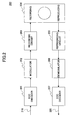
- FIG.1 is a diagram illustrating ECC (error correcting code) sectors, their respective data formats, and a corresponding recording data sequence according to a conventional scheme.
- the recording data includes plural ECC sectors, ECC sector 0 (100), ECC sector 1 (110), ECC sector 2n-1 (120), and ECC sector 2n (130).
- each ECC sector is further divided into plural data blocks.
- the ECC sector 0 (100) includes data 0/0 (101), data 0/1 (102), and data 0/15 (103) as data blocks.
- Each data block includes header information that indicates the head of the data block and data contents.
- a data recording/reproducing apparatus uses an error correcting code (ECC) to accurately restore data recorded on a recording medium.
- ECC error correcting code
- the data recording/reproducing apparatus reproduces data of a recording medium
- the data reproduced from the recording medium may be erred or parts of the data may be skipped due to influence of dust and scratches, for example, on the recording medium. Accordingly, redundancy data are added to the original recording data so that data may be accurately reproduced from the recording medium even when such data error occurs, and the redundancy data are used to correct errors and inadequacies upon relaying the data.
- ECC format the parity code and the CRC code are known.
- the Reed-Solomon code is known as a representative format for the ECC. Any of these ECC formats may be used to encode data recorded on a recording medium to generate an ECC sector therefrom.
- an ECC sector corresponds to a group of data that are encoded by an error correcting code.
- an ECC sector such as the ECC sector ECC 0 (100) of FIG.1 may be divided into data blocks such as data 0/0 (101), data 0/1 (102), and data 0/15 (103), for example.
- Each data block may be arranged to include a header at its front end portion for enabling detection of the head of the data block upon reproducing the data block.
- the data blocks divided in the above-described manner may then be recorded on a recording medium.
- the recording data sequence shown in part (C) of FIG.1 indicates the order in which the divided data blocks of the ECC sectors are to be recorded. As is shown in this drawing, the data sequence is recorded according to the order in which the divided data blocks are arranged.
- FIG.2 is a block diagram showing an exemplary configuration of a data recording/reproducing apparatus.
- the data recording/reproducing apparatus 200 of FIG.2 includes an ECC encoder 201, a modulator 202, a recording circuit 203, a recording medium 204, a reproducing circuit 205, a demodulator 206, and an ECC decoder 207.
- recording data 210 that are to be recorded on the recording medium 204 are supplied to the ECC encoder 201.
- data may be encoded and divided into data blocks in the manner described above. Then, the data divided into data blocks are transmitted to the modulator 202.
- the divided data are modulated into a modulation code that is suited for the present recording/reproducing system implementing the recording medium 204.
- a modulation code that is suited for the present recording/reproducing system implementing the recording medium 204.
- the (1, 7) RLL (run length limited) code or the EFM (eight to fourteen modulation ) code may be used as the modulation code in a case where the recording medium 204 corresponds to an optical disk.
- the modulated data obtained at the modulator 202 are then transmitted to the recording circuit 203.
- the recording circuit 203 converts the modulated data into a recording signal, and supplies the recording signal to a recording head so that the modulated data may be recorded on the recording medium.
- a reproducing signal that is detected from the recording medium 204 by a reproducing head is reproduced by the reproducing circuit 205.
- the reproducing signal is then transmitted to the demodulator circuit 206.
- the demodulator circuit 206 demodulates the modulated code data that are modulated in the manner described above to reproduce the data blocks.
- the reproduced data blocks are then transmitted to the ECC decoder 207.
- the ECC decoder 207 accumulates the divided data blocks to generate an ECC sector, and then corrects error data within the generated ECC sector to output decoded data 220.
- recording media such as the optical disk, the magneto-optical disk, the magnetic disk, and the magnetic tape have partial defects that are created during their manufacture. Additionally, defective portions of commutative media such as optical disks and magnetic tape may increase owing to influences from dust and scratches created by mishandling of the media. As is described above, the ECC is provided in order to correct such errors occurring in the reproduced signal.
- Data decoding using the iterative decoding scheme is an effective method for accurately decoding data in a case where the SNR (signal to noise ratio) of the signal decreases.
- the likelihood information represented by such a burst error signal may be significantly different from the likelihood information that may be represented by the correct data.
- influences from the differing likelihood information may be propagated to the other correctly reproduced data through prior information obtained from a previous decoding result that is used in the data decoding. In this way, error propagation may occur, and desired effects of the iterative decoding may not be sufficiently obtained.
- the above described problem may be solved by handling a data block containing the burst error as lost data in the iterative decoding process and conducting an error correction process at the ECC decoder.
- a burst error resides over two data blocks, these two data blocks need to be handled as lost data.
- error correction required for the lost data may be beyond the error correction capacity of the ECC so that the required error correction may not be realized.
- the present invention has been conceived in response to the one or more problems of the related art and its object is to provide a data format, a data recording/reproducing method, and a data recording/reproducing apparatus for realizing a more effective correction of data errors generated due to dust and scratches on a recording medium even when using conventional ECC.
- the present invention provides a data recording/reproducing apparatus, including an error correction encoder that conducts error correction encoding on input data; an iterative encoder that conducts iterative encoding on data output from the error correction encoder; a generation unit that generates iterative encoded data units by dividing an ECC sector including an error correction code generated by the error correction encoder into prescribed data units and conducting iterative encoding by the iterative encoder on each of the prescribed data units, and generates predetermined data units constituted by the iterative encoded data units; a recording unit that records the predetermined data units constituted by the iterative encoded data units on a recording medium; a reproducing unit that reproduces the predetermined data units from the recording medium; an iterative decoder that conducts iterative decoding on the reproduced predetermined data units; an error correction decoder that conducts error correction on data output by the iterative decoder; the apparatus characterized by comprising:
- the present invention provides a data recording/reproducing apparatus, including an error correction encoder that conducts error correction encoding on input data; a generation unit that generates predetermined data units by dividing an ECC sector including an error correction code generated by the error correction encoder into the predetermined data units; a recording unit that records the predetermined data units generated by the generation unit on a recording medium; an error correction decoder that conduct error correction on data reproduced from the recording medium; the apparatus being characterized by comprising: a distribution unit that distributes the predetermined data units generated by the generation unit, the distribution unit being configured to realize the data distribution in units of the predetermined data units using at least two ECC sectors, and output the distributed predetermined data units to the recording unit to be recorded on the recording medium.
- the distribution is realized in a manner such that the predetermined data units of a same ECC sector are arranged in a non-consecutive order.
- an apparatus of the present invention further includes a memory having a data capacity that is greater than or equal to the amount of data of an ECC sector to be distributed.
- the distribution involves interchanging odd numbered predetermined data units of differing ECC sectors.
- the distribution involves interchanging odd numbered predetermined data units of one ECC sector with even numbered predetermined data units of another ECC sector.
- the recording unit and the reproducing unit when the recording unit and the reproducing unit are capable of recording or reproducing at least two data blocks simultaneously, the recording unit and the reproducing unit distribute the predetermined data units of at least two ECC sectors.
- an apparatus of the present invention further includes a data buffer configured to monitor continuity of the input data.
- the data buffer determines that the input data continue over a data amount that is greater than or equal to a data amount for two ECC sectors, data of the two ECC sectors are distributed and recorded on the recording medium.
- the data buffer determines that the input data continue over a data amount that is less than or equal to a data amount for a single ECC sector, data of the single ECC sector and recorded data or dummy data are distributed and recorded.
- a file allocation table is referred to for determining whether unrecorded sectors for recording data of two ECC sectors are available within the recording medium.
- an apparatus of the present invention further includes a burst error detector.
- the error correction decoder processes data reproduced from the recording medium as lost data.
- the iterative encoder attaches parity codes to the iterative encoded data units, and the iterative decoder uses the parity codes to determine whether the iterative encoded data units that are reproduced from the recording medium correspond to lost data.
- the distribution is realized using at least three ECC sectors.
- the predetermined data units are distributed and recorded on differing tracks of the recording medium.
- the predetermined data units are distributed and recorded on a fore side and a rear side of the recording medium.
- the present invention provides a data recording/reproducing method, including an error correction encoding step of conducting error correction encoding on input data; an iterative encoding step of conducting iterative encoding on data output in the error correction encoding step; a generation step of generating iterative encoded data units through dividing an ECC sector including an error correction code generated in the error correction encoding step into prescribed data units and conducting the iterative encoding of the iterative encoding step on each of the prescribed data units, and generating predetermined data units constituted by the iterative encoded data units; a recording step of recording the predetermined data units constituted by the iterative encoded data units on a recording medium; a reproducing step of reproducing the predetermined data units from the recording medium; an iterative decoding step of conducting iterative decoding on the reproduced predetermined data units; and an error correction decoding step of conducting error correction on data output by the iterative decoding step; the method being characterized by further comprising:
- the present invention provides a data recording/reproducing method including an error correction encoding step of conducting error correction encoding on input data; a generation step of generating predetermined data units by dividing an ECC sector including an error correction code generated in the error correction encoding step into the predetermined data units; a recording step of recording the predetermined data units generated in the generation step on a recording medium; and an error correction decoding step of conducting error correction on data reproduced from the recording medium; the method being characterized by further comprising:
- the positions of data blocks (data units) into which one ECC sector is divided are interchanged with the positions of the data blocks of another ECC sector to realize data distribution recording.
- a long burst error spanning plural data blocks of an ECC sector occurs owing to the presence of dust or scratches on the recording medium.
- the burst error may be beyond the error correction capacity of the ECC, and error correction may not be effectively realized.
- data recorded using a format according to an embodiment of the present invention are arranged such that data blocks are distributed over plural ECC sectors, and thereby, a burst error originating from defects at the recording medium may be take the form of short errors scattered over plural ECC sectors.
- the data blocks may be distributed over plural ECC sectors upon data recording so that the number of data units (blocks) that may be handled as lost data may be increased and error correction may be accurately realized for longer burst errors compared to the convention system.
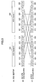
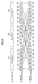
- FIG.3 is a diagram illustrating a data distribution scheme according to a first embodiment of the present invention. Specifically, this drawing illustrates a data interleaving or distributing method conducted by a data recording/reproducing apparatus in which the positions of even numbered data blocks of one ECC sector and odd numbered data blocks of another ECC sector are interchanged.
- the positions of odd numbered data blocks of ECC sector 0 (410) and even numbered data blocks of ECC sector 1 (420) are interchanged. That is, the ECC sector 0 (410) of the ECC sectors shown in part (A) of FIG.3 includes data blocks D 0/0 (411), D 0/1 (412), D 0/2 (413), D 0/3 (414), D 0/4 (415), and D 0/5 (416) before an interleaving process as is shown in part (B) of FIG.3.
- the ECC sector 1 (420) of the ECC sectors shown in part (A) of FIG.3 includes data blocks D 1/0 (421), D 1/1 (422), D 1/2 (423), D 1/3 (424), D 1/4 (425), and D 1/5 (426) before the interleaving process.
- the positions of the odd numbered data blocks D 0/1 (412), D 0/3 (414), and D 0/5 (416) and the even numbered data blocks D 1/0 (421), D 1/2 (423), and D 1/4 (425) are interchanged.
- data blocks of differing ECC sectors are sequentially recorded on the recording medium, namely, the data blocks are recorded in the following sequence: D 0/0 (411), D 1/0 (421), D 0/2 (413), D 1/2 (423), D 0/4 (415), D 1/4 (425), D 0/1 (412), D 1/1 (422), D 0/3 (414), D 1/3 (424), D 0/5 (416), and D 1/5 (426).
- the data blocks sustaining the error in the original ECC frame may be distributed and the ECC may be combined to realize error correction.
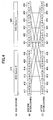
- FIG.4 illustrates a data distribution scheme according to a second embodiment of the present invention.
- This drawing illustrates a data interleaving method that is conducted by a data recording/reproducing apparatus in which the positions of odd numbered data blocks of one ECC sector and odd numbered data blocks of another ECC sector are interchanged. It is noted that elements shown in the present drawing that are identical to those shown in FIG.3 are given the same numerical references.
- the positions of odd numbered data blocks of ECC sector 0 (410) and odd numbered data blocks of ECC sector 1 (420) are interchanged. That is, the ECC sector 0 (410) of the ECC sectors shown in part (A) of FIG.4 includes data blocks D 0/0 (411), D 0/1 (412), D 0/2 (413), D 0/3 (414), D 0/4 (415), and D 0/5 (416) before an interleaving process as is shown in part (B) of FIG.4.
- the ECC sector 1 (420) of the ECC sectors shown in part (A) of FIG.4 includes data blocks D 1/0 (421), D 1/1 (422), D 1/2 (423), D 1/3 (424), D 1/4 (425), and D 1/5 (426) before the interleaving process.
- the positions of the odd numbered data blocks D 0/1 (412), D 0/3 (414), and D 0/5 (416) of ECC sector 0 (410) and the odd numbered data blocks D 1/1 (422), D 1/3 (424), and D 1/5 (426) of ECC sector 1 (420) are interchanged.
- the data blocks of the differing ECC sectors are sequentially recorded on the recording medium, namely, the data blocks are recorded in the following sequence: D 0/0 (411), D 1/1 (422), D 0/2 (413), D 1/3 (424), D 0/4 (415), D 1/5 (426), D 1/0 (421), D 0/1 (412), D 1/2 (423), D 0/3 (414), D 1/4 (425), and D 0/5 (416).
- FIG.5 illustrates an exemplary data format implementing the data distribution scheme of the second embodiment.
- the data distribution scheme according to the second embodiment of interchanging the positions of odd numbered data blocks of one ECC sector and odd numbered data blocks of another ECC sector is applied to the ECC sectors shown in part (A) and the data block formats of the ECC sectors shown in part (B) that are identical to the ECC sectors and data block formats shown in FIG.1 to generate a recording data sequence as is shown in part (C) of FIG.5.
- the odd numbered data blocks such as data 0/1 (102) of the ECC sector 0 (100) and the odd numbered data blocks such as data 1/1 (112) of the ECC sector 1 (110) are interchanged. In this way the recording order of the data blocks may be changed with respect to the recording data sequence shown in part (C) of FIG.1.
- the interleaving process conducted by the data recording/reproducing apparatus involves interchanging the positions of the odd numbered data blocks of an ECC sector and the odd numbered data blocks of another ECC sector.
- the interleaving process may also be realized by interchanging the positions of even numbered data blocks of an ECC sector and even numbered data blocks of another ECC sector.
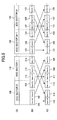
- FIG.6 is a diagram illustrating a data distribution scheme (three sector scheme) according to a third embodiment of the present invention.
- the present embodiment involves interchanging the positions of data blocks of three differing ECC sectors so that the data blocks of each ECC sector may be distributed over the three ECC frames. It is noted that elements shown in FIG.6 that are identical to those shown in FIG.3 are given the same numerical references.
- the ECC sector 0 (410) of the ECC sectors shown in part (A) of FIG.6 includes data blocks D 0/0 (411), D 0/1 (412), D 0/2 (413), D 0/3 (414), D 0/4 (415), and D 0/5 (416) before an interleaving process as is shown in part (B) of FIG.6.
- the ECC sector 1 (420) of the ECC sectors shown in part (A) of FIG.6 includes data blocks D 1/0 (421), D 1/1 (422), D 1/2 (423), D 1/3 (424), D 1/4 (425), and D 1/5 (426) before the interleaving process.
- ECC sector 2 (430) of the ECC sectors shown in part (A) of FIG.6 includes data blocks D 2/0 (431), D 2/1 (432), D 2/2 (433), D 2/3 (434), D 2/4 (435), and D 2/5 (436) before the interleaving process.
- the 0 th data block D 0/0 (411) of the ECC sector 0 (410), the 0 th data block D 1/0 (421) of the ECC sector 1 (420), and the 0 th data block D 2/0 (431) of the ECC sector 2 (430) are gathered together.
- the 3 rd data block D 0/3 (414) of the ECC sector 0 (410), the 3 rd data block D 1/3 (424) of the ECC sector 1 (420), and the 3 rd data block D 2/3 (434) of the ECC sector 2 (430) are gathered together.
- the data blocks to be recorded are arranged in the following sequence: D 0/0 (411), D 1/0 (421), D 2/0 (431), D 0/3 (414), D 1/3 (424), D 2/3 (434), and so on, as is shown in part (C) of FIG.6.
- FIG.7 is a diagram illustrating an exemplary data format implementing the data distribution scheme of the third embodiment. It is noted that part (A) of FIG.7 represents ECC sectors of encoded data, part (B) represents data block formats of the ECC sectors, and part (C) represents a recording data sequence.
- the recording data sequence of FIG.7 is arranged according to the data distribution scheme of the third embodiment in which data blocks are successively extracted from the ECC sector 0, the ECC sector 1, and the ECC sector 2, respectively, and rearranged into a predetermined sequence: D 0/0 (701), D 1/0 (711), D 2/0 (721), ... , D 2/12 (724), D 0/1 (702), D 1/1 (712), D 2/1 (722), ... , and so on.
- data blocks of an ECC sector are distributed over three ECC frames.
- the present embodiment is not limited to this example, and the data blocks may also be distributed over more than three ECC sectors.
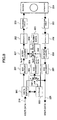
- FIG.8 is a diagram illustrating a configuration of a data recording/reproducing apparatus for realizing data distribution recording according to a fourth embodiment of the present invention.
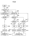
- FIG.9 is a flowchart illustrating an operation of the data recording/reproducing apparatus of the fourth embodiment for realizing the data distribution recording.
- the data recording/reproducing apparatus of the fourth embodiment as is shown in FIG.8 for realizing data distribution recording includes an ECC encoder 201, a modulator 202, a recording circuit 203, a recording medium 204, a reproducing circuit 205, a demodulator 206, an ECC demodulator 207, a data buffer 801, a controller 802, a first switch 803, an ECC encoder 804, a dummy data generator 805, a second switch 806, an interleaver 807, and a de-interleaver 808.
- step S901 of FIG.9 the data recording/reproducing apparatus of FIG.8 acquires user data 210 that are divided into recording units according to a logical format (e.g., 2 KB or 32 KB according to the data size supported by the operating system (OS)), the data being supplied to the data buffer 801 from a superordinate apparatus such as a personal computer via an interface provided between the superordinate apparatus and the data recording/reproducing apparatus.
- a superordinate apparatus such as a personal computer via an interface provided between the superordinate apparatus and the data recording/reproducing apparatus.
- ECC encoding/decoding is conducted in units of the data size into which the supplied user data 210 are divided.
- step S902 the supplied user data 210 are taken in by the data buffer 801 while monitoring the data size thereof. Specifically, the controller 802 monitors the data size to determine whether the supplied data may need to use two or more ECC sectors, and controls the first switch according to the determination result. If the supplied data continue over two or more EC sectors, the operation proceeds to step S903.
- step S903 a file allocation table that is recorded at a predetermined location of the recording medium is referred to in order to find an area in which data extending over two ECC sectors may be recorded.
- step S904 a determination is made as to whether an unrecorded area that may store two ECC sectors of data has been found. If such unrecorded area for storing two ECC sectors of data is found, the operation proceeds to step S905.
- step S905 positions 'a' for the first switch and the second switch, respectively, are selected by the controller 802.
- step S906 data (In-D1) of one ECC sector are ECC encoded by the ECC encoder 201, and data (In-D2) of the other ECC sector are input to the ECC encoder 804 via the first switch 803 to be ECC encoded. Then, the data (In-D1) and (In-D2) of the two ECC sectors that are ECC encoded at the ECC encoders 201 and 804, respectively, may be rearranged by the interleaver 807 according to the data distribution scheme of FIG.3, for example, to obtain a data sequence in which data blocks of the same ECC sector may be positioned apart from one another.
- step S907 data interleaved by the interleaver 807 are transmitted to the modulator 202 to be modulated by a suitable modulation code for recording and reproducing.
- a suitable modulation code for recording and reproducing.
- the (1, 7) RLL code or the EFM modulation code may be used as is described above.
- the recording circuit 203 may record the modulated data on the unrecorded area of the recording medium 204 for two ECC sectors of data that has been detected in step S904.
- the file allocation table may be referred to in order to locate the data distributed over plural locations. Then, the data recorded at the respective locations may be reproduced by the reproducing circuit 205, and the reproduced data may be modulated by the modulation circuit 206. Then, the modulated data may be rearranged back to the data sequence state prior to being interleaved or distributed by the de-interleaver 808, after which error correction may be conducted on errors included in the reproduced data by the EC decoder 207 so that the resulting data may be reproduced as user data 220.
- step S902 When it is determined in step S902 that the input user data 210 does not continue over two ECC sectors, namely, only one ECC sector is required to encode the user data 210, the operation proceeds to step S908.
- step S908 the file allocation table is referred to in order to find an available recording area within the recording medium 204 for storing one ECC sector of data.
- states of two consecutive sectors n-1 and n of the recording medium 204 may be classified into the following three categories:
- step S909 if it is determined in step S909 that sector n-1 is unrecorded (recordable) and it is also determined in step S910 that sector n is unrecorded (recordable) as well (corresponding to case (1)), the operation proceeds to step S911.
- the first switch may be set to any position and the second switch is set to position b.
- step S912 the data encoded at the ECC encoder 201 and dummy data generated by the dummy data generator 805 are interleaved by the interleaver 807 in the manner described above.
- step S913 the data interleaved by the interleaver 807 are transmitted to the modulator 202 to be modulated by a suitable modulation code for realizing data recording/reproduction.
- a suitable modulation code for realizing data recording/reproduction.
- the (1, 7) RLL code or the EFM modulation code may be used as is described above.
- the recording circuit 203 may record the modulated data on the two sectors of the recording medium 204 that have been detected as unrecorded areas. It is noted that the dummy data may be handled as unrecorded in cases (2) and (3).
- step S909 If it is determined in step S909 that sector n-1 is unrecorded (recordable) and it is determined in step S910 that sector n is already recorded (corresponding to case (2)), the operation proceeds to step S914.
- step S914 the controller 802 sets the first switch 803 to position 'b' and sets the second switch 806 to position 'a'.
- step S915 data that are already recorded are reproduced by the reproducing circuit 205, demodulated by the demodulation circuit 206, de-interleaved by the de-interleaver 808, and reproduced (ECC decoded) by the ECC decoder 207.
- the reproduced data are transmitted from the first switch 803 to the ECC encoder 804 to be ECC encoded again.
- the encoded data are interleaved with the data encoded by the ECC encoder 201 by the interleaver 807.
- step S913 the interleaved data are recorded on the recording medium 204 in the manner described above.
- step 909 If it is determined in step 909 that sector n-1 is already recorded and it is determined in step S916 that sector n is unrecorded (recordable) (corresponding to case (3)), the operation proceeds to step S917.
- step S917 the first switch 803 is set to position 'b' and the second switch 806 is set to position 'a'.
- step S918 the already recorded data are reproduced by the reproducing circuit 205, demodulated by the demodulator 206, de-interleaved by the de-interleaver 808, and reproduced (ECC decoded) by the ECC decoder 206. Then, the reproduced data are transmitted from the first switch 803 to the ECC encoder 804 to be encoded again. Then, the encoded data are interleaved with the data encoded at the ECC encoder 201 by the interleaver 807.
- step S913 the interleaved data are recorded on the recording medium 204 in the manner described above.
- step S916 If it is determined in step S916 that sector n is already recorded, the operation proceeds back to step S908 in which the file allocation table is referred to in order to find a recording area on the recording medium 204 for recording one sector of data.
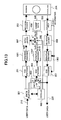
- FIG.10 is a block diagram illustrating a configuration of a data recording/reproducing apparatus (parallel recording system) for realizing data distribution recording according to a fifth embodiment of the present invention. It is noted that elements shown in FIG.10 that are identical to those shown in FIG.8 are given the same numerical references.
- the data recording/reproducing apparatus of FIG.10 for realizing data distribution recording includes a third switch 1001 and a fourth switch 1002 in addition to the elements included in the data recording/reproducing apparatus of FIG.8. Further, in the data recording/reproducing apparatus according to the present embodiment, the recording circuit 203 of FIG.8 is divided into two recording circuits 203-1 and 203-2, and the reproducing circuit 205 of FIG.8 is divided into two reproducing circuits 205-1 and 205-2.
- an optical disk apparatus implements single optical heads for recording and reproducing, respectively, since optical heads tend to be expensive.
- a configuration as described above may be realized in an optical disk apparatus.
- plural optical heads may be provided at one side of a recording medium or at both sides of the recording medium.
- a recording head 1 and a reproducing head 1 are provided at the fore side surface of the recording medium 204 and a recording head 2 and a reproducing head 2 are provided at a rear side surface of the recording medium 204.
- a data sequence including data blocks that are distributed over plural ECC sector frames in a discontinuous arrangement is modulated into a suitable modulation code for realizing data recording and reproduction, and the third switch 1001 is controlled by the controller 802 to realize data recording on the fore side and rear side of the recording medium 204, respectively.
- the recording data sequence of data 0/0, data 1/1, ..., data 1/15 may be recorded on the fore side of the recording medium 204 and the recording data sequence of data 1/0, data 0/1, ..., data 0/15 may be recorded on the rear side of the recording medium 204 in a parallel manner.
- reproducing heads 1 and 2 are used to reproduce data recorded on the respective sides of the recording medium 204, and the fourth switch 1002 is used to successively output the reproduced data to the demodulation circuit 206.
- the recording circuits 203-1 and 203-2 and the reproducing circuits 205-1 and 205-2 are arranged to be parallel; however, the modulator 202 and demodulator 206 may also be arranged to have parallel configurations and the recording data on the fore side of the recording medium 204 and the recording data on the rear side of the recording medium 204 may be separated at the interleaver 807 and de-interleaver 808, for example.
- the recording system and the reproducing system are each arranged into two system configurations; however, the recording system and the reproducing system may also be arranged to have three or more systems as well. Further, the optical heads of the systems may be provided at the same side of the recording to record/reproduce data on/from different tracks, for example.
- FIG.11 shows a configuration of a data recording/reproducing apparatus that conducts iterative decoding.
- the data recording/reproducing apparatus of FIG.11 includes an ECC encoder 201, an iterative encoder 1101, a recording circuit 203, a recording medium 204, a reproducing circuit 205, an iterative decoder 1102, and an ECC decoder 207.
- data recording is realized by ECC encoding input user data 210 with the ECC encoder 210, and encoding the data again with the iterative encoder 1101 using an iterative code. Then, the data encoded by the iterative encoder 1101 may be recorded on the recording medium 204 through the recording circuit 203.
- the data are divided into block units (iterative block data) for conducting iterative decoding.
- iterative code a recursive convolution code may be used so that iterative decoding may be realized.
- data reproduction may be realized by decoding recorded data in block units for iterative decoding by the iterative decoder 1102, and ECC decoding the iterative decoded data by the ECC decoder 207 to reproduce user data 220.
- FIG.12 is a diagram illustrating an exemplary case in which a data distribution scheme according to an embodiment of the present invention is applied to a system implementing iterative decoding.
- the principles of the data distribution scheme of FIG.5 are applied; however, when such a data distribution scheme is applied to iterative decoding, the data are distributed in iterative decoding block units (BD) so that data blocks of the same ECC sector of the recording medium 204 may be positioned apart from one another to realize a discontinuous arrangement of the recording data.
- BD iterative decoding block units
- FIG.13 is a block diagram illustrating a configuration of an iterative decoding recording/reproducing apparatus that realizes data distribution recording according to a sixth embodiment of the present invention. It is noted that elements shown in FIG.13 that are identical to those shown in FIG.8 are given the same numerical references.
- the iterative decoding recording/reproducing apparatus of FIG.13 includes the elements shown in FIG.8 except for the modulator 202 and the demodulator 206, and also includes iterative encoders 1301 and 1302, and an iterative decoder 1303.
- the operation of the iterative decoding recording/reproducing apparatus of FIG.13 is similar to the operation of the data recording/reproducing apparatus of FIG.8.
- further encoding is conducted by the iterative encoders 1301 and 1302 using an iterative code, after which the encoded data are interleaved by the interleaver 807 and recorded on the recording medium 204 in a manner such that data blocks of the same ECC sector may not be consecutively arranged within the same sector of the recording medium 204.
- a reproducing signal is transmitted to the de-interleaver 808 via the reproducing circuit 205 to be de-interleaved, after which the de-interleaved data are decoded at the iterative decoder 1303 and ECC decoded at the ECC decoder 207.
- FIG.14 is a block diagram illustrating an exemplary configuration of a burst error detection circuit that may be included in the reproducing circuit 205 shown in FIG.13.
- the burst error detection circuit of FIG.14 includes comparators 1401 and 1402, shift registers 1403 and 1404, and a logical OR gate 1405. Reproduced data y i that are input to the comparators 1401 and 1402 are compared to comparison levels 1420 and 1430, respectively, at the comparators 1401 and 1402. The comparison results are then input to the shift registers 1403 and 1404.
- the shift register 1403 stores comparison results in which the amount of the reproduced data y i is determined to be greater than the predetermined comparison level 1420.
- the shift register 1404 stores comparison results in which the amount of the reproduced data y i is determined to be less than the predetermined comparison level 1430. Then, a logical sum (OR) of the comparison results stored in the shift resisters 1403 and 1404 is calculated by the OR gate 1405, and output as a burst error detection result.
- the burst error detection circuit 1400 of FIG.14 the occurrence of a burst error within a reproducing signal may be monitored.
- burst information is supplied to the iterative decoder 1303 and ECC decoder 207 to control the number of iterations, or a flag for indicating that the burst error be handled as lost data may be sent.
- the ECC decoder 207 may conduct lost data compensation.
- parity codes e.g.
- the iterative decoder 1303 may be arranged to handle the reproducing data as lost data upon detecting data errors of more than a predetermined amount (including random errors), and the ECC decoder 207 may be arranged to process the reproduced data as lost data.
- FIG.15 is a diagram illustrating an exemplary impact of a burst error on data reproduction.
- FIG.16 is a diagram illustrating an advantageous effect that may be realized by an embodiment of the present invention with respect to the impact of a burst error.
- part (A) shows ECC sectors 1510 and 1520 at the time of encoding
- part (B) shows data blocks 1511, 1512, 1513, 1521, 1522, and 1523 of a recording data sequence
- part (C) shows ECC sectors 1530 and 1540 at the time of data decoding.
- the error correction capacity of the ECC allows error correction of up to 80 data units
- a burst error 1550 of 100 data units is generated across two data blocks 1511 and 1512 in the example of FIG.15, this results in a data error of 100 data units within one ECC sector so that error correction may not be effectively realized by the ECC in the ECC sector 1530.
- the two data blocks may be distributed over two differing ECC sectors 1530 and 1540 and the data error may be divided into two data error parts each amounting to 50 data units, for example, so that error correction may be effectively realized on the data error and accurate data decoding may be realized.
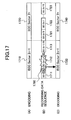
- FIG.17 illustrates an exemplary impact of a burst error on data reproduction in a system implementing iterative decoding.
- FIG.18 illustrates an advantageous effect that may be realized by an embodiment of the present invention with respect to the impact of a burst error occurring in the system implementing iterative decoding.
- part (A) shows ECC sectors 1710 and 1720 at the time of data encoding
- part (B) shows data blocks 1711, 1712, 1713, 1721, 1722, 1723 of a recording data sequence
- part (C) shows ECC sectors 1730 and 1740 at the time of decoding.
- the ECC is able to handle 5 blocks of lost data
- a burst error 1750 occurs is generated across seven iterative decoding blocks in the example shown in FIG.17
- the data in the ECC sector 1730 may not be accurately decoded.
- the burst error may be distributed as four blocks of lost data in ECC sector 1730 and three blocks of lost data in ECC sector 1740 so that error correction may be realized by the ECC in both ECC sectors 1730 and 1740.
- a data recording/reproducing system that has an enhanced error correction capacity for handling such long burst errors and thereby having a high decoding capacity may be realized without changing the ECC.
Landscapes
- Engineering & Computer Science (AREA)
- Signal Processing (AREA)
- Multimedia (AREA)
- Signal Processing For Digital Recording And Reproducing (AREA)
- Error Detection And Correction (AREA)
Abstract
A data format, a data recording/reproducing
method, and a data recording/reproducing apparatus
are provided for effectively correcting data errors
caused by dust and scratches on a recording medium
even with the use of a conventional ECC. The data
recording/reproducing apparatus includes a
generation unit that generates predetermined data
units by dividing an ECC sector including error
correction codes generated by an error correction
encoder into prescribed data units and encoding the
prescribed units into iterative encoded data units
using an iterative encoder so that the predetermined
data units may consist of the iterative-encoded data
units, a recording unit, a reproducing unit, an
iterative decoder for conducting iterative decoding
on the predetermined data units, and an error
correction decoder. The apparatus further includes
a distribution unit for distributing the
predetermined data units generated by the generation
unit. The distribution unit distributes the
iterative encoded data units using at least two ECC
sectors and records the distributed data units on a
recording medium.
Description
The present invention relates generally to a
data format for data being recorded on a recording
medium, a data recording/reproducing apparatus, and
a data recording /reproducing method. The present
invention particularly relates to a data format for
realizing effective error correction for errors that
occur due to dust and/or scratches, for example, on
the recording medium.
Various types of data recording/reproducing
apparatuses exist including those for recording data
on a recording medium such as a magnetic disk, a
magnetic tape, an optical disk, and a magneto-optical
disk. To record data on these recording
media, a magnetic recording mark is usually used.
These recording media are less expensive than
semiconductor memory and are able to store data on a
permanent basis. Also, these recording media are
widely used as information recording media for
computers to handle large amounts of information
such as images and image information. It is desired
that a recording/reproducing apparatus for recording
data on such recording media be able to operate with
high reliability and effectively correct data errors
occurring as a result of dust and scratches on the
recording media.
FIG.1 is a diagram illustrating ECC (error
correcting code) sectors, their respective data
formats, and a corresponding recording data sequence
according to a conventional scheme. As is shown in
part (A) of FIG.1, the recording data includes
plural ECC sectors, ECC sector 0 (100), ECC sector 1
(110), ECC sector 2n-1 (120), and ECC sector 2n
(130). As is shown in part (B) of FIG.1, each ECC
sector is further divided into plural data blocks.
For example, the ECC sector 0 (100) includes data
0/0 (101), data 0/1 (102), and data 0/15 (103) as
data blocks. Each data block includes header
information that indicates the head of the data
block and data contents.
A data recording/reproducing apparatus uses an
error correcting code (ECC) to accurately restore
data recorded on a recording medium. When the data
recording/reproducing apparatus reproduces data of a
recording medium, the data reproduced from the
recording medium may be erred or parts of the data
may be skipped due to influence of dust and
scratches, for example, on the recording medium.
Accordingly, redundancy data are added to the
original recording data so that data may be
accurately reproduced from the recording medium even
when such data error occurs, and the redundancy data
are used to correct errors and inadequacies upon
relaying the data.
As the ECC format, the parity code and the CRC
code are known. Also, the Reed-Solomon code is
known as a representative format for the ECC. Any
of these ECC formats may be used to encode data
recorded on a recording medium to generate an ECC
sector therefrom. In other words, an ECC sector
corresponds to a group of data that are encoded by
an error correcting code. Further, an ECC sector
such as the ECC sector ECC 0 (100) of FIG.1 may be
divided into data blocks such as data 0/0 (101),
data 0/1 (102), and data 0/15 (103), for example.
Each data block may be arranged to include a header
at its front end portion for enabling detection of
the head of the data block upon reproducing the data
block.
The data blocks divided in the above-described
manner may then be recorded on a recording medium.
The recording data sequence shown in part (C) of
FIG.1 indicates the order in which the divided data
blocks of the ECC sectors are to be recorded. As is
shown in this drawing, the data sequence is recorded
according to the order in which the divided data
blocks are arranged.
In the following, the data
recording/reproducing apparatus that conducts such
an operation is described. FIG.2 is a block diagram
showing an exemplary configuration of a data
recording/reproducing apparatus. The data
recording/reproducing apparatus 200 of FIG.2
includes an ECC encoder 201, a modulator 202, a
recording circuit 203, a recording medium 204, a
reproducing circuit 205, a demodulator 206, and an
ECC decoder 207.
In the case of recording data on the recording
medium 204, first, recording data 210 that are to be
recorded on the recording medium 204 are supplied to
the ECC encoder 201. At the ECC encoder 201, data
may be encoded and divided into data blocks in the
manner described above. Then, the data divided into
data blocks are transmitted to the modulator 202.
At the modulator 202, the divided data are
modulated into a modulation code that is suited for
the present recording/reproducing system
implementing the recording medium 204. For example,
the (1, 7) RLL (run length limited) code or the EFM
(eight to fourteen modulation ) code may be used as
the modulation code in a case where the recording
medium 204 corresponds to an optical disk. The
modulated data obtained at the modulator 202 are
then transmitted to the recording circuit 203.
The recording circuit 203 converts the
modulated data into a recording signal, and supplies
the recording signal to a recording head so that the
modulated data may be recorded on the recording
medium.
In the case of reproducing data from the
recording medium 204, a reproducing signal that is
detected from the recording medium 204 by a
reproducing head is reproduced by the reproducing
circuit 205. The reproducing signal is then
transmitted to the demodulator circuit 206.
The demodulator circuit 206 demodulates the
modulated code data that are modulated in the manner
described above to reproduce the data blocks. The
reproduced data blocks are then transmitted to the
ECC decoder 207.
The ECC decoder 207 accumulates the divided
data blocks to generate an ECC sector, and then
corrects error data within the generated ECC sector
to output decoded data 220.
Generally, recording media such as the optical
disk, the magneto-optical disk, the magnetic disk,
and the magnetic tape have partial defects that are
created during their manufacture. Additionally,
defective portions of commutative media such as
optical disks and magnetic tape may increase owing
to influences from dust and scratches created by
mishandling of the media. As is described above,
the ECC is provided in order to correct such errors
occurring in the reproduced signal.
However, as technology develops for increasing
the recording density of a recording medium, a dust
particle or a scratch of the same size in such an
advanced system may affect a larger amount of data
compared to the conventional system. Thereby, dust
particles and scratches of the same size in the
advanced system may result in the generation of a
greater number of data errors compared to the
conventional system.
Data decoding using the iterative decoding
scheme, which is presently gaining much attention,
is an effective method for accurately decoding data
in a case where the SNR (signal to noise ratio) of
the signal decreases. However, in the case of
decoding a reproduced signal including an error that
may occur upon its reproduction due to defects in
the recording medium (e.g., burst error signal), the
likelihood information represented by such a burst
error signal may be significantly different from the
likelihood information that may be represented by
the correct data. In such case, influences from the
differing likelihood information may be propagated
to the other correctly reproduced data through prior
information obtained from a previous decoding result
that is used in the data decoding. In this way,
error propagation may occur, and desired effects of
the iterative decoding may not be sufficiently
obtained.
The above described problem may be solved by
handling a data block containing the burst error as
lost data in the iterative decoding process and
conducting an error correction process at the ECC
decoder. However, when a burst error resides over
two data blocks, these two data blocks need to be
handled as lost data. In such case, error
correction required for the lost data may be beyond
the error correction capacity of the ECC so that the
required error correction may not be realized.
The present invention has been conceived in
response to the one or more problems of the related
art and its object is to provide a data format, a
data recording/reproducing method, and a data
recording/reproducing apparatus for realizing a more
effective correction of data errors generated due to
dust and scratches on a recording medium even when
using conventional ECC.
To achieve the above object, the present
invention, according to a first aspect, provides a
data recording/reproducing apparatus, including
an error correction encoder that conducts error correction encoding on input data;
an iterative encoder that conducts iterative encoding on data output from the error correction encoder;
a generation unit that generates iterative encoded data units by dividing an ECC sector including an error correction code generated by the error correction encoder into prescribed data units and conducting iterative encoding by the iterative encoder on each of the prescribed data units, and generates predetermined data units constituted by the iterative encoded data units;
a recording unit that records the predetermined data units constituted by the iterative encoded data units on a recording medium;
a reproducing unit that reproduces the predetermined data units from the recording medium;
an iterative decoder that conducts iterative decoding on the reproduced predetermined data units;
an error correction decoder that conducts error correction on data output by the iterative decoder; the apparatus characterized by comprising:
an error correction encoder that conducts error correction encoding on input data;
an iterative encoder that conducts iterative encoding on data output from the error correction encoder;
a generation unit that generates iterative encoded data units by dividing an ECC sector including an error correction code generated by the error correction encoder into prescribed data units and conducting iterative encoding by the iterative encoder on each of the prescribed data units, and generates predetermined data units constituted by the iterative encoded data units;
a recording unit that records the predetermined data units constituted by the iterative encoded data units on a recording medium;
a reproducing unit that reproduces the predetermined data units from the recording medium;
an iterative decoder that conducts iterative decoding on the reproduced predetermined data units;
an error correction decoder that conducts error correction on data output by the iterative decoder; the apparatus characterized by comprising:
The present invention, according to another
aspect, provides a data recording/reproducing
apparatus, including
an error correction encoder that conducts error correction encoding on input data;
a generation unit that generates predetermined data units by dividing an ECC sector including an error correction code generated by the error correction encoder into the predetermined data units;
a recording unit that records the predetermined data units generated by the generation unit on a recording medium;
an error correction decoder that conduct error correction on data reproduced from the recording medium; the apparatus being characterized by comprising:
a distribution unit that distributes the predetermined data units generated by the generation unit, the distribution unit being configured to realize the data distribution in units of the predetermined data units using at least two ECC sectors, and output the distributed predetermined data units to the recording unit to be recorded on the recording medium.
an error correction encoder that conducts error correction encoding on input data;
a generation unit that generates predetermined data units by dividing an ECC sector including an error correction code generated by the error correction encoder into the predetermined data units;
a recording unit that records the predetermined data units generated by the generation unit on a recording medium;
an error correction decoder that conduct error correction on data reproduced from the recording medium; the apparatus being characterized by comprising:
a distribution unit that distributes the predetermined data units generated by the generation unit, the distribution unit being configured to realize the data distribution in units of the predetermined data units using at least two ECC sectors, and output the distributed predetermined data units to the recording unit to be recorded on the recording medium.
According to a preferred embodiment of the
present invention, the distribution is realized in a
manner such that the predetermined data units of a
same ECC sector are arranged in a non-consecutive
order.
According to another preferred embodiment, an
apparatus of the present invention further includes
a memory having a data capacity that is greater than
or equal to the amount of data of an ECC sector to
be distributed.
According to another preferred embodiment of
the present invention, the distribution involves
interchanging odd numbered predetermined data units
of differing ECC sectors.
According to another preferred embodiment of
the present invention, the distribution involves
interchanging odd numbered predetermined data units
of one ECC sector with even numbered predetermined
data units of another ECC sector.
According to another preferred embodiment of
the present invention, when the recording unit and
the reproducing unit are capable of recording or
reproducing at least two data blocks simultaneously,
the recording unit and the reproducing unit
distribute the predetermined data units of at least
two ECC sectors.
According to another preferred embodiment, an
apparatus of the present invention further includes
a data buffer configured to monitor continuity of
the input data.
According to another preferred embodiment of
the present invention, when the data buffer
determines that the input data continue over a data
amount that is greater than or equal to a data
amount for two ECC sectors, data of the two ECC
sectors are distributed and recorded on the
recording medium.
According to another preferred embodiment of
the present invention, when the data buffer
determines that the input data continue over a data
amount that is less than or equal to a data amount
for a single ECC sector, data of the single ECC
sector and recorded data or dummy data are
distributed and recorded.
According to another preferred embodiment of
the present invention, a file allocation table is
referred to for determining whether unrecorded
sectors for recording data of two ECC sectors are
available within the recording medium.
According to another preferred embodiment of
the present invention, when unrecorded sectors for
recording data of two ECC sectors are available,
data of an ECC sector generated by the input data
and dummy data are used to realize the distribution.
According to another preferred embodiment of
the present invention, when an unrecorded sector for
recording data of one ECC sector is available in the
recording medium, data of one sector recorded on the
recording medium are reproduced, and the reproduced
data of said one sector and data of another ECC
sector generated by the input data are distributed
and recorded on the recording medium.
According to another preferred embodiment, an
apparatus of the present invention further includes
a burst error detector.
According to another preferred embodiment of
the present invention, when a burst error is
detected by the burst error detector, the error
correction decoder processes data reproduced from
the recording medium as lost data.
According to another preferred embodiment of
the present invention, the iterative encoder
attaches parity codes to the iterative encoded data
units, and the iterative decoder uses the parity
codes to determine whether the iterative encoded
data units that are reproduced from the recording
medium correspond to lost data.
According to another preferred embodiment of
the present invention, the distribution is realized
using at least three ECC sectors.
According to another preferred embodiment of
the present invention, the predetermined data units
are distributed and recorded on differing tracks of
the recording medium.
According to another preferred embodiment of
the present invention, the predetermined data units
are distributed and recorded on a fore side and a
rear side of the recording medium.
Further, the present invention, according to
another aspect, provides a data
recording/reproducing method, including
an error correction encoding step of conducting error correction encoding on input data;
an iterative encoding step of conducting iterative encoding on data output in the error correction encoding step;
a generation step of generating iterative encoded data units through dividing an ECC sector including an error correction code generated in the error correction encoding step into prescribed data units and conducting the iterative encoding of the iterative encoding step on each of the prescribed data units, and generating predetermined data units constituted by the iterative encoded data units;
a recording step of recording the predetermined data units constituted by the iterative encoded data units on a recording medium;
a reproducing step of reproducing the predetermined data units from the recording medium;
an iterative decoding step of conducting iterative decoding on the reproduced predetermined data units; and
an error correction decoding step of conducting error correction on data output by the iterative decoding step; the method being characterized by further comprising:
an error correction encoding step of conducting error correction encoding on input data;
an iterative encoding step of conducting iterative encoding on data output in the error correction encoding step;
a generation step of generating iterative encoded data units through dividing an ECC sector including an error correction code generated in the error correction encoding step into prescribed data units and conducting the iterative encoding of the iterative encoding step on each of the prescribed data units, and generating predetermined data units constituted by the iterative encoded data units;
a recording step of recording the predetermined data units constituted by the iterative encoded data units on a recording medium;
a reproducing step of reproducing the predetermined data units from the recording medium;
an iterative decoding step of conducting iterative decoding on the reproduced predetermined data units; and
an error correction decoding step of conducting error correction on data output by the iterative decoding step; the method being characterized by further comprising:
Also, the present invention, according to
another aspect, provides a data
recording/reproducing method including
an error correction encoding step of conducting error correction encoding on input data;
a generation step of generating predetermined data units by dividing an ECC sector including an error correction code generated in the error correction encoding step into the predetermined data units;
a recording step of recording the predetermined data units generated in the generation step on a recording medium; and
an error correction decoding step of conducting error correction on data reproduced from the recording medium; the method being characterized by further comprising:
an error correction encoding step of conducting error correction encoding on input data;
a generation step of generating predetermined data units by dividing an ECC sector including an error correction code generated in the error correction encoding step into the predetermined data units;
a recording step of recording the predetermined data units generated in the generation step on a recording medium; and
an error correction decoding step of conducting error correction on data reproduced from the recording medium; the method being characterized by further comprising:
According to an aspect of the present invention,
the positions of data blocks (data units) into which
one ECC sector is divided are interchanged with the
positions of the data blocks of another ECC sector
to realize data distribution recording. Upon
reproducing data recorded on a recording medium,
there may be cases in which a long burst error
spanning plural data blocks of an ECC sector occurs
owing to the presence of dust or scratches on the
recording medium. In such case, in a conventional
system, the burst error may be beyond the error
correction capacity of the ECC, and error correction
may not be effectively realized. However, data
recorded using a format according to an embodiment
of the present invention are arranged such that data
blocks are distributed over plural ECC sectors, and
thereby, a burst error originating from defects at
the recording medium may be take the form of short
errors scattered over plural ECC sectors.
Thus, according to an aspect of the present
invention, longer burst errors may be corrected
compared to the conventional system and high density
data recording/reproduction may be realized.
Also, it is noted that in systems using
iterative decoding, when a burst error occurs, such
data are generally handled as lost data. According
to an aspect of the present invention, the data
blocks may be distributed over plural ECC sectors
upon data recording so that the number of data units
(blocks) that may be handled as lost data may be
increased and error correction may be accurately
realized for longer burst errors compared to the
convention system. By incorporating one or more
features of the present invention with iterative
decoding, high density data recording/reproduction
may be effectively realized.
Other objects, features and advantages of the
present invention will become more apparent from the
following detailed description when read in
conjunction with the accompanying drawings.
In the following, preferred embodiments of the
present invention are described with reference to
the accompanying drawings.
FIG.3 is a diagram illustrating a data
distribution scheme according to a first embodiment
of the present invention. Specifically, this
drawing illustrates a data interleaving or
distributing method conducted by a data
recording/reproducing apparatus in which the
positions of even numbered data blocks of one ECC
sector and odd numbered data blocks of another ECC
sector are interchanged.
In the example of FIG.3, the positions of odd
numbered data blocks of ECC sector 0 (410) and even
numbered data blocks of ECC sector 1 (420) are
interchanged. That is, the ECC sector 0 (410) of
the ECC sectors shown in part (A) of FIG.3 includes
data blocks D 0/0 (411), D 0/1 (412), D 0/2 (413), D
0/3 (414), D 0/4 (415), and D 0/5 (416) before an
interleaving process as is shown in part (B) of
FIG.3. The ECC sector 1 (420) of the ECC sectors
shown in part (A) of FIG.3 includes data blocks D
1/0 (421), D 1/1 (422), D 1/2 (423), D 1/3 (424), D
1/4 (425), and D 1/5 (426) before the interleaving
process.
Upon performing the interleaving process, the
positions of the odd numbered data blocks D 0/1
(412), D 0/3 (414), and D 0/5 (416) and the even
numbered data blocks D 1/0 (421), D 1/2 (423), and D
1/4 (425) are interchanged. As a result, as is
shown in part (C) of FIG.3, data blocks of differing
ECC sectors are sequentially recorded on the
recording medium, namely, the data blocks are
recorded in the following sequence: D 0/0 (411), D
1/0 (421), D 0/2 (413), D 1/2 (423), D 0/4 (415), D
1/4 (425), D 0/1 (412), D 1/1 (422), D 0/3 (414), D
1/3 (424), D 0/5 (416), and D 1/5 (426).
By distributing the data blocks over two ECC
frames upon recording the data blocks on the
recording medium, even when a data error such as a
burst error occurs, the data blocks sustaining the
error in the original ECC frame may be distributed
and the ECC may be combined to realize error
correction.
FIG.4 illustrates a data distribution scheme
according to a second embodiment of the present
invention. This drawing illustrates a data
interleaving method that is conducted by a data
recording/reproducing apparatus in which the
positions of odd numbered data blocks of one ECC
sector and odd numbered data blocks of another ECC
sector are interchanged. It is noted that elements
shown in the present drawing that are identical to
those shown in FIG.3 are given the same numerical
references.
In the example of FIG.4, the positions of odd
numbered data blocks of ECC sector 0 (410) and odd
numbered data blocks of ECC sector 1 (420) are
interchanged. That is, the ECC sector 0 (410) of
the ECC sectors shown in part (A) of FIG.4 includes
data blocks D 0/0 (411), D 0/1 (412), D 0/2 (413), D
0/3 (414), D 0/4 (415), and D 0/5 (416) before an
interleaving process as is shown in part (B) of
FIG.4. The ECC sector 1 (420) of the ECC sectors
shown in part (A) of FIG.4 includes data blocks D
1/0 (421), D 1/1 (422), D 1/2 (423), D 1/3 (424), D
1/4 (425), and D 1/5 (426) before the interleaving
process.
Upon performing the interleaving process, the
positions of the odd numbered data blocks D 0/1
(412), D 0/3 (414), and D 0/5 (416) of ECC sector 0
(410) and the odd numbered data blocks D 1/1 (422),
D 1/3 (424), and D 1/5 (426) of ECC sector 1 (420)
are interchanged. As a result, as is shown in part
(C) of FIG.3, after the interleaving process, the
data blocks of the differing ECC sectors are
sequentially recorded on the recording medium,
namely, the data blocks are recorded in the
following sequence: D 0/0 (411), D 1/1 (422), D 0/2
(413), D 1/3 (424), D 0/4 (415), D 1/5 (426), D 1/0
(421), D 0/1 (412), D 1/2 (423), D 0/3 (414), D 1/4
(425), and D 0/5 (416).
FIG.5 illustrates an exemplary data format
implementing the data distribution scheme of the
second embodiment. In the example of FIG.5, the
data distribution scheme according to the second
embodiment of interchanging the positions of odd
numbered data blocks of one ECC sector and odd
numbered data blocks of another ECC sector is
applied to the ECC sectors shown in part (A) and the
data block formats of the ECC sectors shown in part
(B) that are identical to the ECC sectors and data
block formats shown in FIG.1 to generate a recording
data sequence as is shown in part (C) of FIG.5. In
the recording data sequence shown in part (C) of
this drawing, the odd numbered data blocks such as
data 0/1 (102) of the ECC sector 0 (100) and the odd
numbered data blocks such as data 1/1 (112) of the
ECC sector 1 (110) are interchanged. In this way
the recording order of the data blocks may be
changed with respect to the recording data sequence
shown in part (C) of FIG.1.
By distributing the data blocks of an ECC
sector over two ECC frames upon recording the data
blocks on a recording medium, even when a data error
such as a burst error occurs, data blocks that
sustain the error in the original frame may be
distributed and the ECC may be combined to realize
error correction.
According to the above-described example using
the second embodiment, the interleaving process
conducted by the data recording/reproducing
apparatus involves interchanging the positions of
the odd numbered data blocks of an ECC sector and
the odd numbered data blocks of another ECC sector.
However, the interleaving process may also be
realized by interchanging the positions of even
numbered data blocks of an ECC sector and even
numbered data blocks of another ECC sector.
FIG.6 is a diagram illustrating a data
distribution scheme (three sector scheme) according
to a third embodiment of the present invention. The
present embodiment involves interchanging the
positions of data blocks of three differing ECC
sectors so that the data blocks of each ECC sector
may be distributed over the three ECC frames. It is
noted that elements shown in FIG.6 that are
identical to those shown in FIG.3 are given the same
numerical references.
In the present example, the ECC sector 0 (410)
of the ECC sectors shown in part (A) of FIG.6
includes data blocks D 0/0 (411), D 0/1 (412), D 0/2
(413), D 0/3 (414), D 0/4 (415), and D 0/5 (416)
before an interleaving process as is shown in part
(B) of FIG.6. The ECC sector 1 (420) of the ECC
sectors shown in part (A) of FIG.6 includes data
blocks D 1/0 (421), D 1/1 (422), D 1/2 (423), D 1/3
(424), D 1/4 (425), and D 1/5 (426) before the
interleaving process. Also, ECC sector 2 (430) of
the ECC sectors shown in part (A) of FIG.6 includes
data blocks D 2/0 (431), D 2/1 (432), D 2/2 (433), D
2/3 (434), D 2/4 (435), and D 2/5 (436) before the
interleaving process.
Upon performing the interleaving process in the
present example, the 0th data block D 0/0 (411) of
the ECC sector 0 (410), the 0th data block D 1/0
(421) of the ECC sector 1 (420), and the 0th data
block D 2/0 (431) of the ECC sector 2 (430) are
gathered together. Then, the 3rd data block D 0/3
(414) of the ECC sector 0 (410), the 3rd data block
D 1/3 (424) of the ECC sector 1 (420), and the 3rd
data block D 2/3 (434) of the ECC sector 2 (430) are
gathered together. Consequently, after the
interleaving process, the data blocks to be recorded
are arranged in the following sequence: D 0/0 (411),
D 1/0 (421), D 2/0 (431), D 0/3 (414), D 1/3 (424),
D 2/3 (434), and so on, as is shown in part (C) of
FIG.6.
FIG.7 is a diagram illustrating an exemplary
data format implementing the data distribution
scheme of the third embodiment. It is noted that
part (A) of FIG.7 represents ECC sectors of encoded
data, part (B) represents data block formats of the
ECC sectors, and part (C) represents a recording
data sequence. The recording data sequence of FIG.7
is arranged according to the data distribution
scheme of the third embodiment in which data blocks
are successively extracted from the ECC sector 0,
the ECC sector 1, and the ECC sector 2, respectively,
and rearranged into a predetermined sequence: D 0/0
(701), D 1/0 (711), D 2/0 (721), ... , D 2/12 (724), D
0/1 (702), D 1/1 (712), D 2/1 (722), ... , and so on.
By distributing the data blocks over three ECC
frames upon recording the data blocks on the
recording medium as is illustrated in the above
example, even when a data error such as a burst
error occurs, data blocks that sustain the error in
the original ECC frame may be distributed, and the
ECC may be combined to realize error correction.
It is noted that in the above described example
implementing the third embodiment, data blocks of an
ECC sector are distributed over three ECC frames.
However, the present embodiment is not limited to
this example, and the data blocks may also be
distributed over more than three ECC sectors.
FIG.8 is a diagram illustrating a configuration
of a data recording/reproducing apparatus for
realizing data distribution recording according to a
fourth embodiment of the present invention. FIG.9
is a flowchart illustrating an operation of the data
recording/reproducing apparatus of the fourth
embodiment for realizing the data distribution
recording.
The data recording/reproducing apparatus of the
fourth embodiment as is shown in FIG.8 for realizing
data distribution recording includes an ECC encoder
201, a modulator 202, a recording circuit 203, a
recording medium 204, a reproducing circuit 205, a
demodulator 206, an ECC demodulator 207, a data
buffer 801, a controller 802, a first switch 803, an
ECC encoder 804, a dummy data generator 805, a
second switch 806, an interleaver 807, and a de-interleaver
808.
In the following, the operation of the data
recording/reproducing apparatus of FIG.8 is
described with reference to FIGS.8 and 9.
In step S901 of FIG.9, the data
recording/reproducing apparatus of FIG.8 acquires
user data 210 that are divided into recording units
according to a logical format (e.g., 2 KB or 32 KB
according to the data size supported by the
operating system (OS)), the data being supplied to
the data buffer 801 from a superordinate apparatus
such as a personal computer via an interface
provided between the superordinate apparatus and the
data recording/reproducing apparatus. Generally,
ECC encoding/decoding is conducted in units of the
data size into which the supplied user data 210 are
divided.
Then, in step S902, the supplied user data 210
are taken in by the data buffer 801 while monitoring
the data size thereof. Specifically, the controller
802 monitors the data size to determine whether the
supplied data may need to use two or more ECC
sectors, and controls the first switch according to
the determination result. If the supplied data
continue over two or more EC sectors, the operation
proceeds to step S903.
In step S903, a file allocation table that is
recorded at a predetermined location of the
recording medium is referred to in order to find an
area in which data extending over two ECC sectors
may be recorded.
Then, in step S904, a determination is made as
to whether an unrecorded area that may store two ECC
sectors of data has been found. If such unrecorded
area for storing two ECC sectors of data is found,
the operation proceeds to step S905.
In step S905, positions 'a' for the first
switch and the second switch, respectively, are
selected by the controller 802.
In step S906, data (In-D1) of one ECC sector
are ECC encoded by the ECC encoder 201, and data
(In-D2) of the other ECC sector are input to the ECC
encoder 804 via the first switch 803 to be ECC
encoded. Then, the data (In-D1) and (In-D2) of the
two ECC sectors that are ECC encoded at the ECC
encoders 201 and 804, respectively, may be
rearranged by the interleaver 807 according to the
data distribution scheme of FIG.3, for example, to
obtain a data sequence in which data blocks of the
same ECC sector may be positioned apart from one
another.
Then, in step S907, data interleaved by the
interleaver 807 are transmitted to the modulator 202
to be modulated by a suitable modulation code for
recording and reproducing. For example, in the case
of recording/reproducing data on/from an optical
disk, the (1, 7) RLL code or the EFM modulation code
may be used as is described above. Then, the
recording circuit 203 may record the modulated data
on the unrecorded area of the recording medium 204
for two ECC sectors of data that has been detected
in step S904.
On the other hand, in the case of reproducing
data of a predetermined ECC sector recorded on the
recording medium 204 in the manner described above,
the file allocation table may be referred to in
order to locate the data distributed over plural
locations. Then, the data recorded at the
respective locations may be reproduced by the
reproducing circuit 205, and the reproduced data may
be modulated by the modulation circuit 206. Then,
the modulated data may be rearranged back to the
data sequence state prior to being interleaved or
distributed by the de-interleaver 808, after which
error correction may be conducted on errors included
in the reproduced data by the EC decoder 207 so that
the resulting data may be reproduced as user data
220.
When it is determined in step S902 that the
input user data 210 does not continue over two ECC
sectors, namely, only one ECC sector is required to
encode the user data 210, the operation proceeds to
step S908.
In step S908, the file allocation table is
referred to in order to find an available recording
area within the recording medium 204 for storing one
ECC sector of data.
It is noted that the states of two consecutive
sectors n-1 and n of the recording medium 204 may be
classified into the following three categories:
Accordingly, if it is determined in step S909
that sector n-1 is unrecorded (recordable) and it is
also determined in step S910 that sector n is
unrecorded (recordable) as well (corresponding to
case (1)), the operation proceeds to step S911.
In step S911, the first switch may be set to
any position and the second switch is set to
position b.
In step S912, the data encoded at the ECC
encoder 201 and dummy data generated by the dummy
data generator 805 are interleaved by the
interleaver 807 in the manner described above.
Then, in step S913, the data interleaved by the
interleaver 807 are transmitted to the modulator 202
to be modulated by a suitable modulation code for
realizing data recording/reproduction. For example,
in the case of recording/reproducing data on/from an
optical disk, the (1, 7) RLL code or the EFM
modulation code may be used as is described above.
Then, the recording circuit 203 may record the
modulated data on the two sectors of the recording
medium 204 that have been detected as unrecorded
areas. It is noted that the dummy data may be
handled as unrecorded in cases (2) and (3).
If it is determined in step S909 that sector n-1
is unrecorded (recordable) and it is determined in
step S910 that sector n is already recorded
(corresponding to case (2)), the operation proceeds
to step S914.
In step S914, the controller 802 sets the first
switch 803 to position 'b' and sets the second
switch 806 to position 'a'.
Then, in step S915, data that are already
recorded are reproduced by the reproducing circuit
205, demodulated by the demodulation circuit 206,
de-interleaved by the de-interleaver 808, and
reproduced (ECC decoded) by the ECC decoder 207.
Then, the reproduced data are transmitted from the
first switch 803 to the ECC encoder 804 to be ECC
encoded again. Then, the encoded data are
interleaved with the data encoded by the ECC encoder
201 by the interleaver 807.
Then the operation proceeds to step S913, and
the interleaved data are recorded on the recording
medium 204 in the manner described above.
If it is determined in step 909 that sector n-1
is already recorded and it is determined in step
S916 that sector n is unrecorded (recordable)
(corresponding to case (3)), the operation proceeds
to step S917.
In step S917, the first switch 803 is set to
position 'b' and the second switch 806 is set to
position 'a'.
Then, in step S918, the already recorded data
are reproduced by the reproducing circuit 205,
demodulated by the demodulator 206, de-interleaved
by the de-interleaver 808, and reproduced (ECC
decoded) by the ECC decoder 206. Then, the
reproduced data are transmitted from the first
switch 803 to the ECC encoder 804 to be encoded
again. Then, the encoded data are interleaved with
the data encoded at the ECC encoder 201 by the
interleaver 807.
Then, the operation proceeds to step S913 where
the interleaved data are recorded on the recording
medium 204 in the manner described above.
If it is determined in step S916 that sector n
is already recorded, the operation proceeds back to
step S908 in which the file allocation table is
referred to in order to find a recording area on the
recording medium 204 for recording one sector of
data.
FIG.10 is a block diagram illustrating a
configuration of a data recording/reproducing
apparatus (parallel recording system) for realizing
data distribution recording according to a fifth
embodiment of the present invention. It is noted
that elements shown in FIG.10 that are identical to
those shown in FIG.8 are given the same numerical
references.
The data recording/reproducing apparatus of
FIG.10 for realizing data distribution recording
according to the fifth embodiment includes a third
switch 1001 and a fourth switch 1002 in addition to
the elements included in the data
recording/reproducing apparatus of FIG.8. Further,
in the data recording/reproducing apparatus
according to the present embodiment, the recording
circuit 203 of FIG.8 is divided into two recording
circuits 203-1 and 203-2, and the reproducing
circuit 205 of FIG.8 is divided into two reproducing
circuits 205-1 and 205-2.
It is noted that generally, an optical disk
apparatus implements single optical heads for
recording and reproducing, respectively, since
optical heads tend to be expensive. However, a
configuration as described above may be realized in
an optical disk apparatus. For example, plural
optical heads may be provided at one side of a
recording medium or at both sides of the recording
medium.
In the example of FIG.10, a recording head 1
and a reproducing head 1 are provided at the fore
side surface of the recording medium 204 and a
recording head 2 and a reproducing head 2 are
provided at a rear side surface of the recording
medium 204. In this case, a data sequence including
data blocks that are distributed over plural ECC
sector frames in a discontinuous arrangement is
modulated into a suitable modulation code for
realizing data recording and reproduction, and the
third switch 1001 is controlled by the controller
802 to realize data recording on the fore side and
rear side of the recording medium 204, respectively.
For example, in recording the data sequence
shown in FIG.5, the recording data sequence of data
0/0, data 1/1, ..., data 1/15 may be recorded on the
fore side of the recording medium 204 and the
recording data sequence of data 1/0, data 0/1, ...,
data 0/15 may be recorded on the rear side of the
recording medium 204 in a parallel manner.
As for reproducing data according to the
present embodiment, reproducing heads 1 and 2 are
used to reproduce data recorded on the respective
sides of the recording medium 204, and the fourth
switch 1002 is used to successively output the
reproduced data to the demodulation circuit 206. It
is noted that in the present example, the recording
circuits 203-1 and 203-2 and the reproducing
circuits 205-1 and 205-2 are arranged to be
parallel; however, the modulator 202 and demodulator
206 may also be arranged to have parallel
configurations and the recording data on the fore
side of the recording medium 204 and the recording
data on the rear side of the recording medium 204
may be separated at the interleaver 807 and de-interleaver
808, for example. Also, it is noted
that in the example described above, the recording
system and the reproducing system are each arranged
into two system configurations; however, the
recording system and the reproducing system may also
be arranged to have three or more systems as well.
Further, the optical heads of the systems may be
provided at the same side of the recording to
record/reproduce data on/from different tracks, for
example.
FIG.11 shows a configuration of a data
recording/reproducing apparatus that conducts
iterative decoding. The data recording/reproducing
apparatus of FIG.11 includes an ECC encoder 201, an
iterative encoder 1101, a recording circuit 203, a
recording medium 204, a reproducing circuit 205, an
iterative decoder 1102, and an ECC decoder 207.
In the data recording/reproducing apparatus as
described above, data recording is realized by ECC
encoding input user data 210 with the ECC encoder
210, and encoding the data again with the iterative
encoder 1101 using an iterative code. Then, the
data encoded by the iterative encoder 1101 may be
recorded on the recording medium 204 through the
recording circuit 203.
Upon encoding, the data are divided into block
units (iterative block data) for conducting
iterative decoding. As for the iterative code, a
recursive convolution code may be used so that
iterative decoding may be realized. Also, in the
present example, data reproduction may be realized
by decoding recorded data in block units for
iterative decoding by the iterative decoder 1102,
and ECC decoding the iterative decoded data by the
ECC decoder 207 to reproduce user data 220.
FIG.12 is a diagram illustrating an exemplary
case in which a data distribution scheme according
to an embodiment of the present invention is applied
to a system implementing iterative decoding. In the
present example, the principles of the data
distribution scheme of FIG.5 are applied; however,
when such a data distribution scheme is applied to
iterative decoding, the data are distributed in
iterative decoding block units (BD) so that data
blocks of the same ECC sector of the recording
medium 204 may be positioned apart from one another
to realize a discontinuous arrangement of the
recording data.
FIG.13 is a block diagram illustrating a
configuration of an iterative decoding
recording/reproducing apparatus that realizes data
distribution recording according to a sixth
embodiment of the present invention. It is noted
that elements shown in FIG.13 that are identical to
those shown in FIG.8 are given the same numerical
references. The iterative decoding
recording/reproducing apparatus of FIG.13 includes
the elements shown in FIG.8 except for the modulator
202 and the demodulator 206, and also includes
iterative encoders 1301 and 1302, and an iterative
decoder 1303.
The operation of the iterative decoding
recording/reproducing apparatus of FIG.13 is similar
to the operation of the data recording/reproducing
apparatus of FIG.8. However, in the present
embodiment, after encoding is conducted by the ECC
encoders 201 and 804, further encoding is conducted
by the iterative encoders 1301 and 1302 using an
iterative code, after which the encoded data are
interleaved by the interleaver 807 and recorded on
the recording medium 204 in a manner such that data
blocks of the same ECC sector may not be
consecutively arranged within the same sector of the
recording medium 204. To realize data reproduction
in the present embodiment, a reproducing signal is
transmitted to the de-interleaver 808 via the
reproducing circuit 205 to be de-interleaved, after
which the de-interleaved data are decoded at the
iterative decoder 1303 and ECC decoded at the ECC
decoder 207.
FIG.14 is a block diagram illustrating an
exemplary configuration of a burst error detection
circuit that may be included in the reproducing
circuit 205 shown in FIG.13. The burst error
detection circuit of FIG.14 includes comparators
1401 and 1402, shift registers 1403 and 1404, and a
logical OR gate 1405. Reproduced data yi that are
input to the comparators 1401 and 1402 are compared
to comparison levels 1420 and 1430, respectively, at
the comparators 1401 and 1402. The comparison
results are then input to the shift registers 1403
and 1404. The shift register 1403 stores comparison
results in which the amount of the reproduced data
yi is determined to be greater than the
predetermined comparison level 1420. The shift
register 1404 stores comparison results in which the
amount of the reproduced data yi is determined to be
less than the predetermined comparison level 1430.
Then, a logical sum (OR) of the comparison results
stored in the shift resisters 1403 and 1404 is
calculated by the OR gate 1405, and output as a
burst error detection result. By using the burst
error detection circuit 1400 of FIG.14, the
occurrence of a burst error within a reproducing
signal may be monitored.
When a burst error having a length that exceeds
a predetermined length in units for iterative
decoding is detected within the reproducing signal
by the burst error detection circuit 1400, burst
information is supplied to the iterative decoder
1303 and ECC decoder 207 to control the number of
iterations, or a flag for indicating that the burst
error be handled as lost data may be sent. In
response to the flag indicating lost data, the ECC
decoder 207 may conduct lost data compensation.
Alternatively, instead of using the burst error
detection circuit 1400, parity codes (e.g. CRC) may
be added to the recording block for iterative
decoding, the iterative decoder 1303 may be arranged
to handle the reproducing data as lost data upon
detecting data errors of more than a predetermined
amount (including random errors), and the ECC
decoder 207 may be arranged to process the
reproduced data as lost data.
FIG.15 is a diagram illustrating an exemplary
impact of a burst error on data reproduction.
FIG.16 is a diagram illustrating an advantageous
effect that may be realized by an embodiment of the
present invention with respect to the impact of a
burst error.
In FIGS.15 and 16, part (A) shows ECC sectors
1510 and 1520 at the time of encoding, part (B)
shows data blocks 1511, 1512, 1513, 1521, 1522, and
1523 of a recording data sequence, and part (C)
shows ECC sectors 1530 and 1540 at the time of data
decoding.
For example, in a case where the error
correction capacity of the ECC allows error
correction of up to 80 data units, if a burst error
1550 of 100 data units is generated across two data
blocks 1511 and 1512 in the example of FIG.15, this
results in a data error of 100 data units within one
ECC sector so that error correction may not be
effectively realized by the ECC in the ECC sector
1530. However, as is illustrated in FIG.16,
according to an embodiment of the present invention,
even when a similar burst error of 100 data units is
generated across two data blocks 1511 and 1512, the
two data blocks may be distributed over two
differing ECC sectors 1530 and 1540 and the data
error may be divided into two data error parts each
amounting to 50 data units, for example, so that
error correction may be effectively realized on the
data error and accurate data decoding may be
realized.
FIG.17 illustrates an exemplary impact of a
burst error on data reproduction in a system
implementing iterative decoding. FIG.18 illustrates
an advantageous effect that may be realized by an
embodiment of the present invention with respect to
the impact of a burst error occurring in the system
implementing iterative decoding.
In FIGS.17 and 18, part (A) shows ECC sectors
1710 and 1720 at the time of data encoding, part (B)
shows data blocks 1711, 1712, 1713, 1721, 1722, 1723
of a recording data sequence, and part (C) shows ECC
sectors 1730 and 1740 at the time of decoding.
For example, in a case where the ECC is able to
handle 5 blocks of lost data, if a burst error 1750
occurs is generated across seven iterative decoding
blocks in the example shown in FIG.17, the data in
the ECC sector 1730 may not be accurately decoded.
However, if the burst error is distributed over two
or more ECC sectors as is shown in the example of
FIG.18, for example, the burst error may be
distributed as four blocks of lost data in ECC
sector 1730 and three blocks of lost data in ECC
sector 1740 so that error correction may be realized
by the ECC in both ECC sectors 1730 and 1740.
As the recording bit size for data recording
becomes smaller due to an increase in recording
density, the impact of dust particles and scratches
on data reproduction becomes greater even when the
size of the dust particle or the scratch itself is
not changed. For example, in a system implementing
a high recording density, the presence of a dust
particle may result in the generation of a long
burst error. However, according to an embodiment of
the present invention, a data recording/reproducing
system that has an enhanced error correction
capacity for handling such long burst errors and
thereby having a high decoding capacity may be
realized without changing the ECC.
Claims (21)
- A data recording/reproducing apparatus, comprising
an error correction encoder that conducts error correction encoding on input data;
an iterative encoder that conducts iterative encoding on data output from the error correction encoder;
a generation unit that generates iterative encoded data units by dividing an ECC sector including an error correction code generated by the error correction encoder into prescribed data units and conducting iterative encoding by the iterative encoder on each of the prescribed data units, and generates predetermined data units constituted by the iterative encoded data units;
a recording unit that records the predetermined data units constituted by the iterative encoded data units on a recording medium;
a reproducing unit that reproduces the predetermined data units from the recording medium;
an iterative decoder that conducts iterative decoding on the reproduced predetermined data units;
an error correction decoder that conducts error correction on data output by the iterative decoder; the apparatus characterized by comprising:a distribution unit that distributes the predetermined data units generated by the generation unit, the distribution unit being configured to realize the data distribution in units of the iterative encoded data units using at least two of the ECC sectors and output the distributed iterative encoded data units to the recording unit to be recorded on the recording medium. - A data recording/reproducing apparatus, comprising
an error correction encoder that conducts error correction encoding on input data;
a generation unit that generates predetermined data units by dividing an ECC sector including an error correction code generated by the error correction encoder into the predetermined data units;
a recording unit that records the predetermined data units generated by the generation unit on a recording medium;
an error correction decoder that conduct error correction on data reproduced from the recording medium; the apparatus being characterized by comprising:a distribution unit that distributes the predetermined data units generated by the generation unit, the distribution unit being configured to realize the data distribution in units of the predetermined data units using at least two of the ECC sectors, and output the distributed predetermined data units to the recording unit to be recorded on the recording medium. - The data recording/reproducing apparatus as claimed in claim 1 or 2, wherein the distribution is realized in a manner such that the predetermined data units of a same one of the ECC sectors are arranged in a non-consecutive order.
- The data recording/reproducing apparatus as claimed in claim 1 or 2, further comprising a memory having a data capacity that is greater than or equal to an amount of data of one of the ECC sectors to be distributed.
- The data recording/reproducing apparatus as claimed in claim 4, wherein the distribution involves interchanging odd numbered predetermined data units of one of the ECC sectors with odd numbered predetermined data units of another one of the ECC sectors.
- The data recording/reproducing apparatus as claimed in claim 4, wherein the distribution involves interchanging odd numbered predetermined data units of one of the ECC sectors with even numbered predetermined data units of another one of the ECC sectors.
- The data recording/reproducing apparatus as claimed in claim 5 or 6, wherein when the recording unit and the reproducing unit are capable of recording or reproducing at least two data blocks simultaneously, the recording unit and the reproducing unit distribute the predetermined data units of at least two of the ECC sectors.
- The data recording/reproducing apparatus as claimed in claim 1 or 2, further comprising a data buffer configured to monitor continuity of the input data.
- The data recording/reproducing apparatus as claimed in claim 8, wherein when the data buffer determines that the input data continue over a data amount that is greater than or equal to a data amount for two ECC sectors, data of the two of the ECC sectors are distributed and recorded on the recording medium.
- The data recording/reproducing apparatus as claimed in claim 8, wherein when the data buffer determines that the input data continue over a data amount that is less than or equal to a data amount for a single one of the ECC sectors, data of the single ECC sector and recorded data or dummy data are distributed and recorded.
- The data recording/reproducing apparatus as claimed in claim 1 or 2, wherein a file allocation table is referred to for determining whether unrecorded sectors for recording data of two of the ECC sectors are available within the recording medium.
- The data recording/reproducing apparatus as claimed in claim 11, wherein when unrecorded sectors for recording data of the two ECC sectors are available, data of the ECC sector generated by the input data and dummy data are used to realize the distribution.
- The data recording/reproducing apparatus as claimed in claim 11, wherein when an unrecorded sector for recording data of one of the ECC sectors is available in the recording medium, data of one sector recorded on the recording medium are reproduced, and the reproduced data of said one sector and data of another one of the ECC sectors generated by the input data are distributed and recorded on the recording medium.
- The data recording/reproducing apparatus as claimed in claim 1 or 2, further comprising a burst error detector.
- The data recording/reproducing apparatus as claimed in claim 14, wherein when a burst error is detected by the burst error detector, the error correction decoder processes data reproduced from the recording medium as lost data.
- The data recording/reproducing apparatus as claimed in claim 1, wherein the iterative encoder attaches parity codes to the iterative encoded data units, and the iterative decoder uses the parity codes to determine whether the iterative encoded data units that are reproduced from the recording medium correspond to lost data.
- The data recording/reproducing apparatus as claimed in claim 1 or 2, wherein the distribution is realized using at least three of the ECC sectors.
- The data recording/reproducing apparatus as claimed in claim 1 or 2, wherein the predetermined data units are distributed and recorded on differing tracks of the recording medium.
- The data recording/reproducing apparatus as claimed in claim 1 or 2, wherein the predetermined data units are distributed and recorded on a fore side and a rear side of the recording medium.
- A data recording/reproducing method, comprising
an error correction encoding step of conducting error correction encoding on input data;
an iterative encoding step of conducting iterative encoding on data output in the error correction encoding step;
a generation step of generating iterative encoded data units through dividing an ECC sector including an error correction code generated in the error correction encoding step into prescribed data units and conducting the iterative encoding of the iterative encoding step on each of the prescribed data units, and generating predetermined data units constituted by the iterative encoded data units;
a recording step of recording the predetermined data units constituted by the iterative encoded data units on a recording medium;
a reproducing step of reproducing the predetermined data units from the recording medium;
an iterative decoding step of conducting iterative decoding on the reproduced predetermined data units; and
an error correction decoding step of conducting error correction on data output by the iterative decoding step; the method being characterized by further comprising:a distribution step of distributing the predetermined data units generated in the generation step, said distribution step including conducting the distribution in units of the iterative encoded data units using at least two of the ECC sectors and outputting the distributed iterative encoded data units to the recording step to realize data recording on the recording medium. - A data recording/reproducing method comprising
an error correction encoding step of conducting error correction encoding on input data;
a generation step of generating predetermined data units by dividing an ECC sector including an error correction code generated in the error correction encoding step into the predetermined data units;
a recording step of recording the predetermined data units generated in the generation step on a recording medium; and
an error correction decoding step of conducting error correction on data reproduced from the recording medium; the method being characterized by further comprising:a distribution step of distributing the predetermined data units generated in the generation step, said distribution step including conducting the distribution in units of the predetermined data units using at least two of the ECC sectors and outputting the distributed predetermined data units to the recording step to realize data recording on the recording medium.
Applications Claiming Priority (1)
| Application Number | Priority Date | Filing Date | Title |
|---|---|---|---|
| PCT/JP2002/012529 WO2004051650A1 (en) | 2002-11-29 | 2002-11-29 | Data recording and reproducing device, and data recording and reproducing method |
Publications (2)
| Publication Number | Publication Date |
|---|---|
| EP1566804A1 true EP1566804A1 (en) | 2005-08-24 |
| EP1566804A4 EP1566804A4 (en) | 2008-04-16 |
Family
ID=32448970
Family Applications (1)
| Application Number | Title | Priority Date | Filing Date |
|---|---|---|---|
| EP02785986A Withdrawn EP1566804A4 (en) | 2002-11-29 | 2002-11-29 | DATA RECORDING, REPRODUCING DEVICE, AND DATA RECORDING AND REPRODUCING METHOD |
Country Status (7)
| Country | Link |
|---|---|
| US (2) | US7430702B2 (en) |
| EP (1) | EP1566804A4 (en) |
| JP (1) | JPWO2004051650A1 (en) |
| KR (1) | KR100591973B1 (en) |
| CN (1) | CN100432945C (en) |
| AU (1) | AU2002354137A1 (en) |
| WO (1) | WO2004051650A1 (en) |
Families Citing this family (9)
| Publication number | Priority date | Publication date | Assignee | Title |
|---|---|---|---|---|
| US8110194B2 (en) * | 2005-12-07 | 2012-02-07 | Medarex, Inc. | CTLA-4 antibody dosage escalation regimens |
| US7747925B2 (en) * | 2006-03-06 | 2010-06-29 | Fujifilm Corporation | Apparatus and method for error correction code striping |
| TWI415118B (en) * | 2006-03-10 | 2013-11-11 | Ibm | Apparatus for embedding information into data |
| US7984367B1 (en) * | 2006-07-25 | 2011-07-19 | Marvell International Ltd. | Method for iterative decoding in the presence of burst errors |
| JP2008112516A (en) * | 2006-10-31 | 2008-05-15 | Fujitsu Ltd | Error correction circuit and information reproducing apparatus |
| JP4932505B2 (en) * | 2007-01-19 | 2012-05-16 | ルネサスエレクトロニクス株式会社 | Optical disk controller and optical disk drive system |
| JP4946844B2 (en) * | 2007-12-13 | 2012-06-06 | ソニー株式会社 | Recording / reproducing apparatus and recording / reproducing method |
| KR100988325B1 (en) * | 2008-10-10 | 2010-10-18 | 포항공과대학교 산학협력단 | Method of distributively recording data on optical disc using error correction codes |
| KR101623730B1 (en) * | 2009-11-23 | 2016-05-25 | 삼성전자주식회사 | Interleaver apparatus |
Family Cites Families (33)
| Publication number | Priority date | Publication date | Assignee | Title |
|---|---|---|---|---|
| JPH0764085B2 (en) * | 1981-06-08 | 1995-07-12 | 富士ゼロックス株式会社 | Thermal recording device |
| US4602295A (en) * | 1982-10-23 | 1986-07-22 | Pioneer Electronic Corporation | Recording and reproducing method for video format signal |
| US4701815A (en) * | 1985-03-11 | 1987-10-20 | Sony Corporation | Tracking servo system for disc memory |
| JP2526875B2 (en) * | 1986-11-05 | 1996-08-21 | ソニー株式会社 | Digital information recorder |
| US5241546A (en) * | 1991-02-01 | 1993-08-31 | Quantum Corporation | On-the-fly error correction with embedded digital controller |
| US5459850A (en) * | 1993-02-19 | 1995-10-17 | Conner Peripherals, Inc. | Flash solid state drive that emulates a disk drive and stores variable length and fixed lenth data blocks |
| JP3687115B2 (en) * | 1994-10-27 | 2005-08-24 | ソニー株式会社 | Playback device |
| GB2295946B (en) * | 1994-12-01 | 1999-09-29 | Mitsubishi Electric Corp | Digital signal recording device,digital signal playback device,and digital signal decoding device therefor |
| US5978958A (en) * | 1995-04-03 | 1999-11-02 | Matsushita Electric Industrial Co., Ltd. | Data transmission system, data recording and reproducing apparatus and recording medium each having data structure of error correcting code |
| JPH09153259A (en) * | 1995-11-30 | 1997-06-10 | Sony Corp | Information recording / reproducing method and apparatus |
| US6112324A (en) * | 1996-02-02 | 2000-08-29 | The Arizona Board Of Regents Acting On Behalf Of The University Of Arizona | Direct access compact disc, writing and reading method and device for same |
| US6058084A (en) * | 1996-02-27 | 2000-05-02 | Sony Corporation | Disk-shaped recording medium using segment ID and disk unit using the disk-shaped recording medium |
| US6511848B2 (en) * | 1996-04-17 | 2003-01-28 | Winfried Albert | Process for producing and multiplying lymphocytes |
| JP3586041B2 (en) * | 1996-04-26 | 2004-11-10 | 株式会社東芝 | Recording data generation method and data reproduction device |
| JPH10188489A (en) | 1996-12-25 | 1998-07-21 | Sony Corp | Optical disk, optical disk recording device and optical disk reproducing device |
| KR100354744B1 (en) * | 1998-08-04 | 2002-12-11 | 삼성전자 주식회사 | Interleave method and circuitry for high density recording media |
| JP3397152B2 (en) * | 1998-12-15 | 2003-04-14 | 松下電器産業株式会社 | Multi-track disc reproducing apparatus and reproducing method thereof |
| FR2790621B1 (en) * | 1999-03-05 | 2001-12-21 | Canon Kk | INTERLEAVING DEVICE AND METHOD FOR TURBOCODING AND TURBODECODING |
| JP3515701B2 (en) * | 1999-03-31 | 2004-04-05 | 松下電器産業株式会社 | Encoding processing device and repetition method |
| JP2001093234A (en) | 1999-09-22 | 2001-04-06 | Matsushita Electric Ind Co Ltd | Disk medium, recording method therefor, recording device and reproducing device |
| JP2001101806A (en) | 1999-09-27 | 2001-04-13 | Hitachi Ltd | Digital signal recording method, its apparatus, and recording medium |
| JP2001169243A (en) * | 1999-12-03 | 2001-06-22 | Sony Corp | Recording apparatus and method, and reproducing apparatus and method |
| US6668349B1 (en) * | 2000-04-14 | 2003-12-23 | Hitachi, Ltd. | Data recording/readback method and data recording/readback device for the same |
| JP4190136B2 (en) * | 2000-06-27 | 2008-12-03 | 富士通株式会社 | Data recording / reproducing device |
| JP3752995B2 (en) * | 2000-09-27 | 2006-03-08 | 日本ビクター株式会社 | Information recording / reproducing device |
| US6604220B1 (en) * | 2000-09-28 | 2003-08-05 | Western Digital Technologies, Inc. | Disk drive comprising a multiple-input sequence detector selectively biased by bits of a decoded ECC codedword |
| US20020078416A1 (en) | 2000-12-01 | 2002-06-20 | Hitachi, Ltd. | Method of recording/reproducing digital data and apparatus for same |
| JP3928414B2 (en) * | 2000-12-01 | 2007-06-13 | 株式会社日立製作所 | DIGITAL DATA RECORDING / REPRODUCING METHOD, DIGITAL DATA RECORDING / REPRODUCING DEVICE, AND RECORDING MEDIUM |
| JP4130534B2 (en) * | 2001-02-07 | 2008-08-06 | 株式会社東芝 | Information recording medium, information recording apparatus, information recording method, information reproducing apparatus, and information reproducing method |
| US7159165B2 (en) * | 2001-04-20 | 2007-01-02 | Samsung Electronics Co., Ltd. | Optical recording medium, data recording or reproducing apparatus and data recording or reproducing method used by the data recording or reproducing apparatus |
| JP2002342942A (en) * | 2001-05-14 | 2002-11-29 | Toshiba Corp | Information storage medium, information recording method, and information recording / reproducing device |
| JP3964634B2 (en) * | 2001-06-14 | 2007-08-22 | 株式会社東芝 | Synchronization code generating method, information recording method, information reproducing method, information reproducing apparatus, and information storage medium |
| KR100833880B1 (en) * | 2001-11-06 | 2008-06-02 | 엘지전자 주식회사 | Optical disc data recorder / method and playback device / method using citron scan |
-
2002
- 2002-11-29 AU AU2002354137A patent/AU2002354137A1/en not_active Abandoned
- 2002-11-29 KR KR1020057002842A patent/KR100591973B1/en not_active Expired - Fee Related
- 2002-11-29 JP JP2004556776A patent/JPWO2004051650A1/en active Pending
- 2002-11-29 CN CNB028294688A patent/CN100432945C/en not_active Expired - Fee Related
- 2002-11-29 EP EP02785986A patent/EP1566804A4/en not_active Withdrawn
- 2002-11-29 WO PCT/JP2002/012529 patent/WO2004051650A1/en not_active Ceased
-
2005
- 2005-01-25 US US11/041,248 patent/US7430702B2/en not_active Expired - Fee Related
-
2008
- 2008-08-19 US US12/194,306 patent/US20090031187A1/en not_active Abandoned
Also Published As
| Publication number | Publication date |
|---|---|
| KR20050074437A (en) | 2005-07-18 |
| AU2002354137A1 (en) | 2004-06-23 |
| CN100432945C (en) | 2008-11-12 |
| US7430702B2 (en) | 2008-09-30 |
| JPWO2004051650A1 (en) | 2006-04-06 |
| WO2004051650A1 (en) | 2004-06-17 |
| EP1566804A4 (en) | 2008-04-16 |
| US20050204257A1 (en) | 2005-09-15 |
| CN1650364A (en) | 2005-08-03 |
| KR100591973B1 (en) | 2006-06-22 |
| US20090031187A1 (en) | 2009-01-29 |
Similar Documents
| Publication | Publication Date | Title |
|---|---|---|
| US20090031187A1 (en) | Data recording/reproducing apparatus and data recording/reproducing method | |
| JP3993035B2 (en) | Data recording method, recording medium, and reproducing apparatus | |
| US6891690B2 (en) | On-drive integrated sector format raid error correction code system and method | |
| CN1815615B (en) | Device and method for confirming defect area on optical media | |
| US20020078416A1 (en) | Method of recording/reproducing digital data and apparatus for same | |
| US20100017679A1 (en) | Recording and reproducing data to/from a recording medium having a user data area and an information area for storing information about the recording medium | |
| US7478306B2 (en) | Method of detecting error location, and error detection circuit, error correction circuit, and reproducing apparatus using the method | |
| WO1995024037A1 (en) | Digital signal encoding method and apparatus, digital signal recording medium, and digital signal decoding method and apparatus | |
| JP2007528566A (en) | Error correction encoding method and apparatus, and error correction decoding method and apparatus | |
| JP3362146B2 (en) | Reproduction device and recording / reproduction device | |
| JP4140344B2 (en) | Decoding device and computer program | |
| JP2005209286A (en) | Data recording method, recording medium, and reproducing device | |
| KR20040108823A (en) | Recording medium, recording method, recording device, and reproduction method and reproducer | |
| JP2001189059A (en) | Recording/reproducing device | |
| JP3476014B2 (en) | Data processing method | |
| JP4079906B2 (en) | Error correction circuit and reproducing apparatus | |
| JP2004348930A (en) | Error correction method and error correction device | |
| JP2005252973A (en) | Data structure and recording medium |
Legal Events
| Date | Code | Title | Description |
|---|---|---|---|
| PUAI | Public reference made under article 153(3) epc to a published international application that has entered the european phase |
Free format text: ORIGINAL CODE: 0009012 |
|
| 17P | Request for examination filed |
Effective date: 20050216 |
|
| AK | Designated contracting states |
Kind code of ref document: A1 Designated state(s): AT BE CH CY DE DK ES FI FR GB GR IE IT LI LU MC NL PT SE TR |
|
| AX | Request for extension of the european patent |
Extension state: AL LT LV MK RO SI |
|
| DAX | Request for extension of the european patent (deleted) | ||
| RBV | Designated contracting states (corrected) |
Designated state(s): DE FR GB |
|
| A4 | Supplementary search report drawn up and despatched |
Effective date: 20080319 |
|
| STAA | Information on the status of an ep patent application or granted ep patent |
Free format text: STATUS: THE APPLICATION HAS BEEN WITHDRAWN |
|
| 18W | Application withdrawn |
Effective date: 20080611 |