EP1566798A1 - Hard disk drive - Google Patents
Hard disk drive Download PDFInfo
- Publication number
- EP1566798A1 EP1566798A1 EP05002287A EP05002287A EP1566798A1 EP 1566798 A1 EP1566798 A1 EP 1566798A1 EP 05002287 A EP05002287 A EP 05002287A EP 05002287 A EP05002287 A EP 05002287A EP 1566798 A1 EP1566798 A1 EP 1566798A1
- Authority
- EP
- European Patent Office
- Prior art keywords
- disk
- hard disk
- disk drive
- base
- blades
- Prior art date
- Legal status (The legal status is an assumption and is not a legal conclusion. Google has not performed a legal analysis and makes no representation as to the accuracy of the status listed.)
- Withdrawn
Links
Images




Classifications
-
- G—PHYSICS
- G11—INFORMATION STORAGE
- G11B—INFORMATION STORAGE BASED ON RELATIVE MOVEMENT BETWEEN RECORD CARRIER AND TRANSDUCER
- G11B25/00—Apparatus characterised by the shape of record carrier employed but not specific to the method of recording or reproducing, e.g. dictating apparatus; Combinations of such apparatus
- G11B25/04—Apparatus characterised by the shape of record carrier employed but not specific to the method of recording or reproducing, e.g. dictating apparatus; Combinations of such apparatus using flat record carriers, e.g. disc, card
- G11B25/043—Apparatus characterised by the shape of record carrier employed but not specific to the method of recording or reproducing, e.g. dictating apparatus; Combinations of such apparatus using flat record carriers, e.g. disc, card using rotating discs
-
- H—ELECTRICITY
- H01—ELECTRIC ELEMENTS
- H01T—SPARK GAPS; OVERVOLTAGE ARRESTERS USING SPARK GAPS; SPARKING PLUGS; CORONA DEVICES; GENERATING IONS TO BE INTRODUCED INTO NON-ENCLOSED GASES
- H01T13/00—Sparking plugs
- H01T13/20—Sparking plugs characterised by features of the electrodes or insulation
- H01T13/32—Sparking plugs characterised by features of the electrodes or insulation characterised by features of the earthed electrode
-
- G—PHYSICS
- G11—INFORMATION STORAGE
- G11B—INFORMATION STORAGE BASED ON RELATIVE MOVEMENT BETWEEN RECORD CARRIER AND TRANSDUCER
- G11B33/00—Constructional parts, details or accessories not provided for in the other groups of this subclass
- G11B33/02—Cabinets; Cases; Stands; Disposition of apparatus therein or thereon
- G11B33/08—Insulation or absorption of undesired vibrations or sounds
-
- G—PHYSICS
- G11—INFORMATION STORAGE
- G11B—INFORMATION STORAGE BASED ON RELATIVE MOVEMENT BETWEEN RECORD CARRIER AND TRANSDUCER
- G11B5/00—Recording by magnetisation or demagnetisation of a record carrier; Reproducing by magnetic means; Record carriers therefor
- G11B5/48—Disposition or mounting of heads or head supports relative to record carriers ; arrangements of heads, e.g. for scanning the record carrier to increase the relative speed
- G11B5/58—Disposition or mounting of heads or head supports relative to record carriers ; arrangements of heads, e.g. for scanning the record carrier to increase the relative speed with provision for moving the head for the purpose of maintaining alignment of the head relative to the record carrier during transducing operation, e.g. to compensate for surface irregularities of the latter or for track following
- G11B5/60—Fluid-dynamic spacing of heads from record-carriers
- G11B5/6005—Specially adapted for spacing from a rotating disc using a fluid cushion
-
- H—ELECTRICITY
- H01—ELECTRIC ELEMENTS
- H01T—SPARK GAPS; OVERVOLTAGE ARRESTERS USING SPARK GAPS; SPARKING PLUGS; CORONA DEVICES; GENERATING IONS TO BE INTRODUCED INTO NON-ENCLOSED GASES
- H01T1/00—Details of spark gaps
- H01T1/20—Means for starting arc or facilitating ignition of spark gap
- H01T1/22—Means for starting arc or facilitating ignition of spark gap by the shape or the composition of the electrodes
-
- G—PHYSICS
- G11—INFORMATION STORAGE
- G11B—INFORMATION STORAGE BASED ON RELATIVE MOVEMENT BETWEEN RECORD CARRIER AND TRANSDUCER
- G11B5/00—Recording by magnetisation or demagnetisation of a record carrier; Reproducing by magnetic means; Record carriers therefor
- G11B5/40—Protective measures on heads, e.g. against excessive temperature
Definitions
- the present invention relates to a hard disk drive, and more particularly, to a hard disk drive with a damping element attenuating vibration during operation of the hard disk drive.
- a hard disk drive is an auxiliary memory unit used in a computer, in which data is read from a magnetic disk and/or new data is written to the magnetic disk by use of a magnetic head.
- FIG. 1 is an exploded view a conventional hard disk drive.
- the hard disk drive 10 includes a disk 15, a spindle motor 20 to turn the disk 15 the spindle motor 20 being connected to a base 11, an actuator 30 supporting a magnetic read/write head 45 writing the data to the disk 15 and/or reading the data from the disk 15, and a cover 12 fastened to the base 11 that covers and protects components inside the hard disk drive 10.
- the disk 15 is secured to a rotator of the spindle motor 20, and turns with respect to the base 11. On a surface of the disk 15, data indicating a position of the data to be written are previously recorded in tens of thousands of tracks formed along a circumference of the disk 15.
- the actuator 30 is rotated around a pivot bearing 33 connected to the base 11 by a voice coil motor 32.
- the actuator 30 includes an arm 35 rotatably coupled to the pivot bearing 33, and a head gimbal assembly (HGA) 37 connected to the arm 35 supporting and biasing a slider 40, on which the magnetic head 45 is mounted, toward the surface of the disk 15.
- HGA head gimbal assembly
- the magnetic head 45 mounted on the slider 40 is spaced a predetermined distance from the rotating disk 15 to write and/or read the data to and/or from the disk 15.
- the conventional hard disk drive 10 there may be vibration due to a structural characteristic or defect of the spindle motor 20, eccentricity of the disk 15, irregular air flow in the hard disk drive 10, etc.
- the vibration adversely affects a position error signal (PES) and a write/read error of the magnetic head 45, and increases noise, thereby deteriorating reliability of the hard disk drive.
- PES position error signal
- a hydrodynamic bearing has been used in the spindle motor 20 of the hard disk drive.
- the spindle motor employing the hydrodynamic bearing can rotate the disk 15 at a high speed above 7200 rpm.
- air flow rotating in the same direction as the rotational direction of the disk as indicated by an arrow D is a major factor causing the disk 15, the actuator 30 and the hard disk drive 10 to vibrate. It is necessary to control the air flow rotating in the direction of arrow D to decrease the vibration of the disk 15, the actuator 30 and the hard disk drive 10 and thus improve the reliability of the hard disk drive.
- the present invention solves the problems of the prior art and provides a hard disk drive with an element guiding air flow generated by the rotation of a disk to an outer edge of the disk to reduce vibration during operation.
- a hard disk drive comprising: a housing including a base and a cover connected to the base; a spindle motor connected to the base; a disk mounted to the spindle motor and rotating with respect to the base; an actuator rotatably connected to the base and including a slider supported by the actuator and a magnetic head mounted on a front end of the slider, the magnetic head writing and/or reading data to and/or from the disk; and a plurality of blades protruding from at least one of a surface of the base or a portion of the cover facing the disk, and guiding an air flow, caused by rotation of the disk, toward an outer edge of the disk.
- respective lines connecting a first end of each of the blades adjacent to a center of the disk with a second end of the respective blades adjacent to the outer edge of the disk are inclined at a predetermined angle in a rotational direction of the disk from a line extending radially from the center of the disk.
- each of the blades curves in a rotational direction of the disk from a first end adjacent to a center of the disk to a second end adjacent to the outer edge of the disk, to have a spiral shape.
- a surface of the blade on which the air flow caused by the rotation of the disk is incident is inclined to guide the air flow to a surface of the disk.
- the blade is disposed before the actuator with respect to a direction of air flow, to block the air flow caused by the rotation of the disk from flowing to the actuator.
- the hard disk drive further comprises a recursive filter outside an outer edge of the disk. Additionally, a first end of one of the blades adjacent to the outer edge of the disk is disposed before the recursive filter with respect to a direction of the air flow, to guide the air flow caused by rotation of the disk toward the recursive filter.
- the blades have the same shape, and are disposed at regular angular intervals.
- FIG. 2 is an exploded view of a hard disk drive according to an embodiment of the present invention.
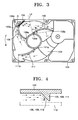
- FIG. 3 is a bottom view of a cover shown in FIG. 2
- FIG. 4 is a cross-sectional view of a blade shown in FIG. 3.
- a hard disk drive 100 includes a housing 101 having a space inside.
- a spindle motor 120, a disk 115, an actuator 130, and a recursive filter 150 are disposed in the space in the housing 101.
- the housing 101 comprises a base 102 supporting the spindle motor 120 and the actuator 130, and a cover 103 connected to an upper portion of the base 102, to protect the disk 115.
- the housing 101 is made of stainless steel or aluminum.
- the disk 115 is disposed in the housing 101.
- the disk 115 may include four or more disks to increase storage capacity, but one or two disks can be used since a surface recording density of disks has increased.
- the hard disk drive 100 shown in FIG. 2 includes one disk, according to one embodiment, the hard disk drive 100 may include two or more disks.
- the spindle motor 120 turns the disk 115 and is fixedly mounted on the base 102.
- a disk clamp 125 is attached to an upper end portion of the spindle motor 120 to prevent the disk 115 from being released.
- the actuator 130 moves a magnetic head 145 to write and read data at a desired position on the disk 115, and includes an arm 137, an HGA 138, and a voice coil motor 135.
- the arm 137 is rotatably coupled to a pivot bearing 132 attached to the base 102.
- the HGA 138 is coupled to a front end portion of the arm 137, and supports and biases a slider 140, on which the magnetic head 145 is mounted toward a surface of the disk 115.
- the voice coil motor 135 provides a driving force to rotate the arm 137, and is controlled by a servo control system.
- the arm 137 is rotated according to Fleming's left-hand rule, in response to interaction between a current input to a VCM coil and a magnetic field generated by magnets.
- the slider 140 attached to a front end portion of the HGA 138 is moved toward the spindle motor 120 on the disk 115 in a direction indicated by an arrow A, and is moved away from the spindle motor 120 in a direction indicated by an arrow B.
- the data can be written on both upper and lower surfaces of the disk 115.
- the arms 137, the HGAs 138, the sliders 140 and the magnetic heads 145 are provided above and below the disk 115, respectively, but the HGA, the slider and the magnetic head disposed under the disk 115, are not visible in the drawings since they are hidden by the disk 115.
- the recursive filter 150 collects and removes foreign substances, such as particles or gas, produced in an interior of the hard disk drive 100, and is detachably connected to an inner surface of the cover 103.
- the recursive filter 150 is positioned at an exterior of the disk 115 to filter the foreign substances, such as particles, flowing with an air flow caused by the rotation of the disk 115.
- the cover 103 of the hard disk drive 100 includes first, second, and third blades 105, 108, and 111 controlling the air flow in the housing 101.
- the blades 105, 108, and 111 protrude from an inner surface of the cover 103 above and toward the disk 115, do not obstruct operation of the actuator 130, and permit operation of the actuator within an operating range 104 of the actuator 130.
- a line L1 connecting a first end 105a of the first blade 105 adjacent to a center of the disk 115 to a second end 105b of the blade 105 farthest from the center of the disk 115 is inclined in an angle ⁇ 1 in the rotational direction D of the disk 115 from a line L2 extending radially from the center of the disk 115.
- the second and third blades 108 and 111 have the same characteristic.
- the blades 105, 108, and 111 gradually curve in the rotational direction D of the disk 115 from the first ends 105a, 108a, and 111a to the second ends 105b, 108b, and 111 b, to form a spiral shape.
- the second end 108b of the second blade 108 adjacent to the outer edge of the disk 115 is disposed adjacent to the recursive filter 150, such that the air flowing in the same direction as the rotational direction D of the disk 115 is guided to the recursive filter 150.
- the air is guided to a gap G positioned between the second end 108b of the second blade 108 and a flange 103a of the cover 102, and passes through the recursive filter 150.
- an amount of air not passing through the recursive filter 150 is reduced, thereby more effectively filtering the foreign substances.
- sides 106, 109, and 112 of the protruded blades 105, 108, and 111 facing the air flow caused by the rotation of the disk 115 are slightly inclined, to guide the air flow toward the surface of the disk 115. Consequently, the air forced toward the outer edge of the disk 115 by the blades 105, 108, and 111 does not form a vortex resulted from blockage by the blades 105, 108, and 111, and thus can be more smoothly guided to the outer edge of the disk 115.
- FIG. 5 is a bottom view of a cover of a hard disk drive according to another embodiment of the present invention.
- the hard disk drive according to the present embodiment has the same components as the hard disk drive according to the previous embodiment in FIG. 2, except that a cover 203 shown in FIG. 5 is used. Elements included in both embodiments are indicated by the same reference numerals, and the difference between the present and previous embodiments will now be described.
- the cover 203 includes first, second, and third blades 205, 208, and 211 protruding from an inner surface of the cover 203 above and toward the disk 115, do not obstruct the operation of the actuator 130, and permit operation of the actuator within an operating range 204 of the actuator 130.
- a line L1' connecting a first end 205a of the blade 205, adjacent the center of the disk 115, to a second end 205b of the blade 205, adjacent to the outer edge of the disk 115, is inclined at an angle ⁇ 2 in the rotational direction D of the disk 115 from a line L2' extending radially from the center of the disk 115.
- the second and third blades 208 and 211 have the same characteristic. But in contrast to the previous embodiment, the blades 205, 208, and 211 curve in a direction opposite to the rotational direction D of the disk 115 from the first ends 205a, 208a, and 211a to the second ends 205b, 208b, and 211b, to form a spiral shape.
- the blades 205, 208, and 211 curve in a direction opposite to the blades 105, 108, and 111 of the previous embodiment.
- the rotating speed of the disk 115 is about 7,200 rpm, although the spiral direction of the blades 205, 208 and 211 is opposite to the rotational direction D of the disk 115, there is no negative influence, such as a vortex, on the air flow.
- vibration of the outer edge of the disk 115 such as fluttering, is prevented due to increased air pressure.
- vortices may form, thereby causing vibrations.
- the second end 208b of the second blade 208 is disposed adjacent to a recursive filter 250, such that the air is guided to a gap G' between the second end 208b of the second blade 208 and a flange 203a of the cover 203, thereby forcing the air to flow through the recursive filter 259, and thus effectively filtering the foreign substances.
- the first blades 105 and 205 are disposed in front of the actuator 130 (with respect to the rotational direction D) as is shown in FIGS. 3 and 5.
- the first blades 105 and 205 block the air flowing to the magnetic head 145, the slider 140 and the HGA 138 of the actuator 130, thereby reducing the vibration of the actuator 130 when the hard disk drive is operating.
- FIGS. 6 and 7 are graphs illustrating characteristics of the hard disk drives illustrated in FIGS. 3 and 5, and the conventional hard disk drive 10 shown in FIG. 1.
- FIG. 6 is a graph illustrating forces applied to the magnetic head
- FIG. 7 is a graph illustrating forces applied to the HGAs.
- Each of the hard disk drives used in the test are two-channel type, which includes a pair of magnetic heads, a pair of sliders, a pair of HGAs, and a pair of arms to record data on both upper and lower surfaces of the disk and read the data from these surfaces. The test was performed at a room temperature under 1 atm, while a rotating speed of the disk was 7,200 rpm.
- the force applied to the magnetic head by the air flow caused by the rotation of the disk is less in the embodiments of FIGS. 3 and 5 than in the conventional hard disk drive 10.
- the force applied to the upper magnetic head closer to the cover is substantially lower in the embodiments of FIGS. 3 and 5.
- the measured applied force in the embodiment of FIG. 3 is slightly less than the measured applied force in the embodiment of FIG. 5.
- the force applied to the HGAs by the air flow caused by the rotation of the disk is less in the embodiments of FIGS. 3 and 5 than in the conventional hard disk drive 10. From the test results, it can be seen that in the hard disk drives of FIGS. 3 and 5, the force applied to the HGA is smaller than in the conventional hard disk drive 10. Therefore, in the embodiments of FIGS. 3 and 5, the vibration of the actuator is reduced, and the PES characteristics and the writing/reading error characteristics are improved compared to a conventional hard disk drive 10.
- a hard disk drive As is described above, in a hard disk drive according to the present invention, air flow is fed to the outer edge of a disk by blades to reduce the vibration of the disk. Also, the air flow to an actuator is blocked by the blades, which reduces the vibration of the actuator. The reduction in the vibration results in an improvement of the PES characteristics and the writing/reading error characteristics, a reduction in noise, and an improvement in the reliability of the hard disk drive.
- the air flow is guided to the recursive filter by the blades, thereby improving the filtering of foreign substances, as is described above.
- the blades are positioned in the base 102, not the cover. 103 According to another embodiment, the blades are positioned in both the base 102 and the cover 103. In addition, according to one embodiment, a plurality of identical blades are disposed at regularly angular intervals in a range not interfering with the operation of the actuator 130.
Landscapes
- Moving Of Heads (AREA)
Abstract
Description
- This application claims the benefit of Korean Patent Application No. 10-2004-0011003, filed on February 19, 2004, in the Korean Intellectual Property Office, the disclosure of which is incorporated herein by reference.
- The present invention relates to a hard disk drive, and more particularly, to a hard disk drive with a damping element attenuating vibration during operation of the hard disk drive.
- A hard disk drive is an auxiliary memory unit used in a computer, in which data is read from a magnetic disk and/or new data is written to the magnetic disk by use of a magnetic head. There has been increasing demand for a hard disk drive with a high speed, a high capacity and a low vibration, and several developments have been made to satisfy this demand.
- FIG. 1 is an exploded view a conventional hard disk drive. Referring to FIG. 1, the
hard disk drive 10 includes adisk 15, aspindle motor 20 to turn thedisk 15 thespindle motor 20 being connected to abase 11, anactuator 30 supporting a magnetic read/writehead 45 writing the data to thedisk 15 and/or reading the data from thedisk 15, and acover 12 fastened to thebase 11 that covers and protects components inside thehard disk drive 10. - The
disk 15 is secured to a rotator of thespindle motor 20, and turns with respect to thebase 11. On a surface of thedisk 15, data indicating a position of the data to be written are previously recorded in tens of thousands of tracks formed along a circumference of thedisk 15. - The
actuator 30 is rotated around a pivot bearing 33 connected to thebase 11 by avoice coil motor 32. Theactuator 30 includes anarm 35 rotatably coupled to the pivot bearing 33, and a head gimbal assembly (HGA) 37 connected to thearm 35 supporting and biasing aslider 40, on which themagnetic head 45 is mounted, toward the surface of thedisk 15. - When the
disk 15 in thehard disk drive 10 is rotated, a lift force is generated in the hard disk drive by air pressure. Theslider 40 is maintained in a floating state on the surface of the disk at a height at which the lift force generated by the rotation of thedisk 15 is in equilibrium with an elastic force of theHGA 37. Accordingly, themagnetic head 45 mounted on theslider 40 is spaced a predetermined distance from the rotatingdisk 15 to write and/or read the data to and/or from thedisk 15. - In the conventional
hard disk drive 10, there may be vibration due to a structural characteristic or defect of thespindle motor 20, eccentricity of thedisk 15, irregular air flow in thehard disk drive 10, etc. The vibration adversely affects a position error signal (PES) and a write/read error of themagnetic head 45, and increases noise, thereby deteriorating reliability of the hard disk drive. - To decrease vibration due to structural characteristics, a hydrodynamic bearing has been used in the
spindle motor 20 of the hard disk drive. The spindle motor employing the hydrodynamic bearing can rotate thedisk 15 at a high speed above 7200 rpm. When thedisk 15 rotates at a high speed, air flow rotating in the same direction as the rotational direction of the disk as indicated by an arrow D is a major factor causing thedisk 15, theactuator 30 and thehard disk drive 10 to vibrate. It is necessary to control the air flow rotating in the direction of arrow D to decrease the vibration of thedisk 15, theactuator 30 and thehard disk drive 10 and thus improve the reliability of the hard disk drive. - The present invention solves the problems of the prior art and provides a hard disk drive with an element guiding air flow generated by the rotation of a disk to an outer edge of the disk to reduce vibration during operation.
- According to an aspect of the present invention, there is provided a hard disk drive comprising: a housing including a base and a cover connected to the base; a spindle motor connected to the base; a disk mounted to the spindle motor and rotating with respect to the base; an actuator rotatably connected to the base and including a slider supported by the actuator and a magnetic head mounted on a front end of the slider, the magnetic head writing and/or reading data to and/or from the disk; and a plurality of blades protruding from at least one of a surface of the base or a portion of the cover facing the disk, and guiding an air flow, caused by rotation of the disk, toward an outer edge of the disk.
- According to one aspect, respective lines connecting a first end of each of the blades adjacent to a center of the disk with a second end of the respective blades adjacent to the outer edge of the disk are inclined at a predetermined angle in a rotational direction of the disk from a line extending radially from the center of the disk.
- According one aspect, each of the blades curves in a rotational direction of the disk from a first end adjacent to a center of the disk to a second end adjacent to the outer edge of the disk, to have a spiral shape.
- According to one aspect, a surface of the blade on which the air flow caused by the rotation of the disk is incident is inclined to guide the air flow to a surface of the disk.
- According to one aspect, the blade is disposed before the actuator with respect to a direction of air flow, to block the air flow caused by the rotation of the disk from flowing to the actuator.
- According to one aspect, the hard disk drive further comprises a recursive filter outside an outer edge of the disk. Additionally, a first end of one of the blades adjacent to the outer edge of the disk is disposed before the recursive filter with respect to a direction of the air flow, to guide the air flow caused by rotation of the disk toward the recursive filter.
- According to one aspect, the blades have the same shape, and are disposed at regular angular intervals.
- Additional aspects and/or advantages of the invention will be set forth in part in the description which follows, and in part, will be obvious from the description, or may be learned by practice of the invention.
- These and/or other aspects and advantages of the invention will become apparent and more readily appreciated from the following description of the embodiments, taken in conjunction with the accompanying drawings of which:
- FIG. 1 is an exploded view of a conventional hard disk drive;
- FIG. 2 is an exploded view of a hard disk drive according to an embodiment of the present invention;
- FIG. 3 is a bottom view of a cover of FIG. 2;
- FIG. 4 is a longitudinal cross-sectional view of a blade of FIG. 3;
- FIG. 5 is a bottom view illustrating a cover of a hard disk drive according to another embodiment of the present invention;
- FIG. 6 is a graph illustrating forces applied to magnetic heads during operation of the hard disk drives shown in FIGS. 1, 3, and 5; and
- FIG. 7 is a graph illustrating forces applied to HGAs during the operation of the hard disk drives shown in FIGS. 1, 3, and 5.
-
- Reference will now be made in detail to embodiments of the present invention, examples of which are illustrated in the accompanying drawings, wherein like reference numerals refer to the like elements throughout. The embodiments are described to explain the present invention by referring to the figures.
- FIG. 2 is an exploded view of a hard disk drive according to an embodiment of the present invention. FIG. 3 is a bottom view of a cover shown in FIG. 2, and FIG. 4 is a cross-sectional view of a blade shown in FIG. 3.
- Referring to FIGS. 2 through 4, a
hard disk drive 100 includes ahousing 101 having a space inside. Aspindle motor 120, adisk 115, anactuator 130, and arecursive filter 150 are disposed in the space in thehousing 101. - The
housing 101 comprises abase 102 supporting thespindle motor 120 and theactuator 130, and acover 103 connected to an upper portion of thebase 102, to protect thedisk 115. According to one embodiment, thehousing 101 is made of stainless steel or aluminum. - As is described above, the
disk 115 is disposed in thehousing 101. Thedisk 115 may include four or more disks to increase storage capacity, but one or two disks can be used since a surface recording density of disks has increased. Although thehard disk drive 100 shown in FIG. 2 includes one disk, according to one embodiment, thehard disk drive 100 may include two or more disks. - The
spindle motor 120 turns thedisk 115 and is fixedly mounted on thebase 102. Adisk clamp 125 is attached to an upper end portion of thespindle motor 120 to prevent thedisk 115 from being released. - The
actuator 130 moves amagnetic head 145 to write and read data at a desired position on thedisk 115, and includes anarm 137, anHGA 138, and avoice coil motor 135. Thearm 137 is rotatably coupled to a pivot bearing 132 attached to thebase 102. The HGA 138 is coupled to a front end portion of thearm 137, and supports and biases aslider 140, on which themagnetic head 145 is mounted toward a surface of thedisk 115. Thevoice coil motor 135 provides a driving force to rotate thearm 137, and is controlled by a servo control system. Thearm 137 is rotated according to Fleming's left-hand rule, in response to interaction between a current input to a VCM coil and a magnetic field generated by magnets. As such, theslider 140 attached to a front end portion of the HGA 138 is moved toward thespindle motor 120 on thedisk 115 in a direction indicated by an arrow A, and is moved away from thespindle motor 120 in a direction indicated by an arrow B. The data can be written on both upper and lower surfaces of thedisk 115. To this end, thearms 137, theHGAs 138, thesliders 140 and themagnetic heads 145 are provided above and below thedisk 115, respectively, but the HGA, the slider and the magnetic head disposed under thedisk 115, are not visible in the drawings since they are hidden by thedisk 115. - The
recursive filter 150 collects and removes foreign substances, such as particles or gas, produced in an interior of thehard disk drive 100, and is detachably connected to an inner surface of thecover 103. Therecursive filter 150 is positioned at an exterior of thedisk 115 to filter the foreign substances, such as particles, flowing with an air flow caused by the rotation of thedisk 115. - The
cover 103 of thehard disk drive 100 includes first, second, andthird blades housing 101. Theblades cover 103 above and toward thedisk 115, do not obstruct operation of theactuator 130, and permit operation of the actuator within anoperating range 104 of theactuator 130. - Referring to FIG. 3, a line L1 connecting a
first end 105a of thefirst blade 105 adjacent to a center of thedisk 115 to asecond end 105b of theblade 105 farthest from the center of thedisk 115 is inclined in an angle α1 in the rotational direction D of thedisk 115 from a line L2 extending radially from the center of thedisk 115. The second andthird blades blades disk 115 from the first ends 105a, 108a, and 111a to the second ends 105b, 108b, and 111 b, to form a spiral shape. Therefore, when thedisk 115 rotates, the air between thedisk 115 and thecover 103 rotates in the same direction as the rotational direction D of thedisk 115, as is shown by dotted arrows in Fig. 3, and is fed to the outer edge of thedisk 115. As such, air pressure between thedisk 115 and thecover 103 gradually increases from the center of thedisk 115 to the outer edge of thedisk 115. As a result, vibrations such as disk fluttering decrease because the outer edge of thedisk 115 is under an influence of the increased air pressure. While Bernoulli's equation would indicate that the air pressure would decrease as the speed of the air increases, use of Bernoulli's equation assumes an incompressible flow, which in this case, is not a valid assumption. - The
second end 108b of thesecond blade 108 adjacent to the outer edge of thedisk 115 is disposed adjacent to therecursive filter 150, such that the air flowing in the same direction as the rotational direction D of thedisk 115 is guided to therecursive filter 150. As such, the air is guided to a gap G positioned between thesecond end 108b of thesecond blade 108 and aflange 103a of thecover 102, and passes through therecursive filter 150. Thus, compared with the case where is noblade 108, an amount of air not passing through therecursive filter 150 is reduced, thereby more effectively filtering the foreign substances. - Referring to FIG. 4, sides 106, 109, and 112 of the protruded
blades disk 115 are slightly inclined, to guide the air flow toward the surface of thedisk 115. Consequently, the air forced toward the outer edge of thedisk 115 by theblades blades disk 115. - FIG. 5 is a bottom view of a cover of a hard disk drive according to another embodiment of the present invention. The hard disk drive according to the present embodiment has the same components as the hard disk drive according to the previous embodiment in FIG. 2, except that a
cover 203 shown in FIG. 5 is used. Elements included in both embodiments are indicated by the same reference numerals, and the difference between the present and previous embodiments will now be described. - Referring to FIG. 5, the
cover 203 includes first, second, andthird blades cover 203 above and toward thedisk 115, do not obstruct the operation of theactuator 130, and permit operation of the actuator within anoperating range 204 of theactuator 130. - A line L1' connecting a
first end 205a of theblade 205, adjacent the center of thedisk 115, to asecond end 205b of theblade 205, adjacent to the outer edge of thedisk 115, is inclined at an angle α2 in the rotational direction D of thedisk 115 from a line L2' extending radially from the center of thedisk 115. The second andthird blades blades disk 115 from the first ends 205a, 208a, and 211a to the second ends 205b, 208b, and 211b, to form a spiral shape. In other words, in the present embodiment, theblades blades disk 115 is about 7,200 rpm, although the spiral direction of theblades disk 115, there is no negative influence, such as a vortex, on the air flow. As in the previous embodiment, vibration of the outer edge of thedisk 115, such as fluttering, is prevented due to increased air pressure. But if the rotating speed of thedisk 115 is increased, vortices may form, thereby causing vibrations. - In the present embodiment, as in the previous embodiment, the
second end 208b of thesecond blade 208 is disposed adjacent to arecursive filter 250, such that the air is guided to a gap G' between thesecond end 208b of thesecond blade 208 and aflange 203a of thecover 203, thereby forcing the air to flow through the recursive filter 259, and thus effectively filtering the foreign substances. - To suppress the vibration of the
actuator 130 caused by the air flowing in the same direction as the rotational direction D of thedisk 115 and colliding against theactuator 130, thefirst blades first blades magnetic head 145, theslider 140 and theHGA 138 of theactuator 130, thereby reducing the vibration of theactuator 130 when the hard disk drive is operating. - FIGS. 6 and 7 are graphs illustrating characteristics of the hard disk drives illustrated in FIGS. 3 and 5, and the conventional
hard disk drive 10 shown in FIG. 1. FIG. 6 is a graph illustrating forces applied to the magnetic head, and FIG. 7 is a graph illustrating forces applied to the HGAs. Each of the hard disk drives used in the test are two-channel type, which includes a pair of magnetic heads, a pair of sliders, a pair of HGAs, and a pair of arms to record data on both upper and lower surfaces of the disk and read the data from these surfaces. The test was performed at a room temperature under 1 atm, while a rotating speed of the disk was 7,200 rpm. - Referring to FIG. 6, the force applied to the magnetic head by the air flow caused by the rotation of the disk is less in the embodiments of FIGS. 3 and 5 than in the conventional
hard disk drive 10. In particular, the force applied to the upper magnetic head closer to the cover is substantially lower in the embodiments of FIGS. 3 and 5. The measured applied force in the embodiment of FIG. 3 is slightly less than the measured applied force in the embodiment of FIG. 5. Referring to FIG. 7, the force applied to the HGAs by the air flow caused by the rotation of the disk is less in the embodiments of FIGS. 3 and 5 than in the conventionalhard disk drive 10. From the test results, it can be seen that in the hard disk drives of FIGS. 3 and 5, the force applied to the HGA is smaller than in the conventionalhard disk drive 10. Therefore, in the embodiments of FIGS. 3 and 5, the vibration of the actuator is reduced, and the PES characteristics and the writing/reading error characteristics are improved compared to a conventionalhard disk drive 10. - As is described above, in a hard disk drive according to the present invention, air flow is fed to the outer edge of a disk by blades to reduce the vibration of the disk. Also, the air flow to an actuator is blocked by the blades, which reduces the vibration of the actuator. The reduction in the vibration results in an improvement of the PES characteristics and the writing/reading error characteristics, a reduction in noise, and an improvement in the reliability of the hard disk drive.
- In addition, the air flow is guided to the recursive filter by the blades, thereby improving the filtering of foreign substances, as is described above.
- Although a few embodiments of the present invention have been shown and described, it would be appreciated by those skilled in the art that changes may be made in these embodiments without departing from the principles and spirit of the invention, the scope of which is defined in the claims and their equivalents. For example, according to one embodiment, the blades are positioned in the
base 102, not the cover. 103 According to another embodiment, the blades are positioned in both thebase 102 and thecover 103. In addition, according to one embodiment, a plurality of identical blades are disposed at regularly angular intervals in a range not interfering with the operation of theactuator 130.
Claims (11)
- A hard disk drive (100) comprising:a housing (101) including a base (102) and a cover (103) connected to the base;a spindle motor (120) connected to the base (102);a disk (115) mounted to the spindle motor (120) and rotating with respect to the base (102); anda plurality of blades (105, 108, 111, 205, 208, 211) protruding from at least one of a surface of the base (102) or a portion of the cover (103) facing the disk (115), and guiding an air flow, caused by rotation of the disk (115), toward an outer edge of the disk (115).
- The hard disk drive of claim 1, comprising:an actuator (130) rotatably connected to the base (102) and including a slider (140) supported by the actuator (130) and a magnetice head (145) mounted on a front end of the slider (140), the magnetic head (145) writing and/or reading data to and/or from the disk (115).
- The hard disk drive of claims 1 or 2, wherein respective lines connecting a first end of each of the blades (105, 108, 111, 205, 208, 211) adjacent to a center of the disk (115) with a second end of the respective blade (105, 108, 111, 205, 208, 211) adjacent to the outer edge of the disk (115) is inclined at a predetermined angle α1 in a rotational direction of the disk (115) from a line (L2) extending radially from the center of the disk (115) and passing through the respective first ends of the blades (105, 108, 111, 205, 208, 211).
- The hard disk drive of any of claims 1 to 3, wherein each of the blades (105, 108, 111, 205, 208, 211) curves in a rotational direction of the disk (115) from a first end adjacent to a center of the disk (115) to a second end adjacent to the outer edge of the disk (115), to have a spiral shape.
- The hard disk drive of any of claims 1 to 4, wherein a surface (106, 109, 112) of the blade (105, 108, 111, 205, 208, 211) on which the air flow caused by the rotation of the disk (115) is incident is inclined to guide the air flow to a surface of the disk (115).
- The hard disk drive of any of claims 1 to 5, wherein the blade (105) is disposed before the actuator (130) with respect to a direction of the air flow, to block the air flow caused by the rotation of the disk (115) from flowing to the actuator (130).
- The hard disk drive of any of claims 1 to 6, further comprising a recursive filter (150) disposed outside an outer edge of the disk (115), wherein an end of one of the blades (108) adjacent to the outer edge of the disk (115) is disposed before the recursive filter (150) with respect to a direction of the air flow, to guide the air flow caused by rotation of the disk toward the recursive filter (150).
- The hard disk drive of any of claims 1 to 7, wherein the blades (105, 108, 111, 205, 208, 211) have the same shape, and are disposed at regular angular intervals.
- The hard disk drive of any of claims 2 to 8, wherein the angle α1 is obtuse or acute.
- A cover (103) for a hard disk drive (100) the hard disk drive (100) having a base (102), to which the cover (103) can be connected, the cover (103) comprising:curved blades (105, 108, 11, 205, 208, 211) extending toward the disk position to guide an air flow induced by rotation of the disk (115) to an outer edge of the disk position to reduce disk vibration.
- The cover of claim 10, wherein one of the blades is positioned upstream of the position of an actuator (130) which is rotatably connected with the base (102) to read and/or write data from and/or to a disk (115).
Applications Claiming Priority (2)
| Application Number | Priority Date | Filing Date | Title |
|---|---|---|---|
| KR1020040011003A KR100564612B1 (en) | 2004-02-19 | 2004-02-19 | Hard disk drive |
| KR2004011003 | 2004-02-19 |
Publications (1)
| Publication Number | Publication Date |
|---|---|
| EP1566798A1 true EP1566798A1 (en) | 2005-08-24 |
Family
ID=34709347
Family Applications (1)
| Application Number | Title | Priority Date | Filing Date |
|---|---|---|---|
| EP05002287A Withdrawn EP1566798A1 (en) | 2004-02-19 | 2005-02-03 | Hard disk drive |
Country Status (5)
| Country | Link |
|---|---|
| US (1) | US7450338B2 (en) |
| EP (1) | EP1566798A1 (en) |
| JP (1) | JP2005235376A (en) |
| KR (1) | KR100564612B1 (en) |
| CN (1) | CN100409361C (en) |
Families Citing this family (44)
| Publication number | Priority date | Publication date | Assignee | Title |
|---|---|---|---|---|
| US7644802B2 (en) * | 2002-11-01 | 2010-01-12 | Seagate Technology Llc | Performance flow guide for improved acoustics |
| US7353524B1 (en) | 2004-06-25 | 2008-04-01 | Western Digital Technologies, Inc. | Disk drive with airflow channeling enclosure |
| US7529062B2 (en) * | 2005-04-20 | 2009-05-05 | Seagate Technology Llc | Formed in place vibration damper or dampers |
| KR100652430B1 (en) * | 2005-09-01 | 2006-12-01 | 삼성전자주식회사 | Particle ejector of hard disk drive and hard disk drive having same |
| KR100660877B1 (en) * | 2005-09-01 | 2006-12-26 | 삼성전자주식회사 | Cover member with air guide and hard disk drive having same |
| SG130179A1 (en) | 2005-09-01 | 2007-03-20 | Samsung Electronics Co Ltd | Particle extracting device of hard disk drive and hard disk drive including the same |
| TWI322985B (en) * | 2005-09-30 | 2010-04-01 | Hon Hai Prec Ind Co Ltd | Optical disc drive |
| US7593181B1 (en) * | 2005-12-16 | 2009-09-22 | Western Digital Technologies, Inc. | Disk vibration damper having an integrated air circulation guide |
| US8839175B2 (en) | 2006-03-09 | 2014-09-16 | Tela Innovations, Inc. | Scalable meta-data objects |
| US7763534B2 (en) | 2007-10-26 | 2010-07-27 | Tela Innovations, Inc. | Methods, structures and designs for self-aligning local interconnects used in integrated circuits |
| US9563733B2 (en) | 2009-05-06 | 2017-02-07 | Tela Innovations, Inc. | Cell circuit and layout with linear finfet structures |
| US8245180B2 (en) | 2006-03-09 | 2012-08-14 | Tela Innovations, Inc. | Methods for defining and using co-optimized nanopatterns for integrated circuit design and apparatus implementing same |
| US7446352B2 (en) | 2006-03-09 | 2008-11-04 | Tela Innovations, Inc. | Dynamic array architecture |
| US8541879B2 (en) | 2007-12-13 | 2013-09-24 | Tela Innovations, Inc. | Super-self-aligned contacts and method for making the same |
| US8225239B2 (en) | 2006-03-09 | 2012-07-17 | Tela Innovations, Inc. | Methods for defining and utilizing sub-resolution features in linear topology |
| US8658542B2 (en) | 2006-03-09 | 2014-02-25 | Tela Innovations, Inc. | Coarse grid design methods and structures |
| US8225261B2 (en) | 2006-03-09 | 2012-07-17 | Tela Innovations, Inc. | Methods for defining contact grid in dynamic array architecture |
| US8448102B2 (en) | 2006-03-09 | 2013-05-21 | Tela Innovations, Inc. | Optimizing layout of irregular structures in regular layout context |
| US9230910B2 (en) | 2006-03-09 | 2016-01-05 | Tela Innovations, Inc. | Oversized contacts and vias in layout defined by linearly constrained topology |
| US9009641B2 (en) | 2006-03-09 | 2015-04-14 | Tela Innovations, Inc. | Circuits with linear finfet structures |
| US7956421B2 (en) | 2008-03-13 | 2011-06-07 | Tela Innovations, Inc. | Cross-coupled transistor layouts in restricted gate level layout architecture |
| US7908578B2 (en) | 2007-08-02 | 2011-03-15 | Tela Innovations, Inc. | Methods for designing semiconductor device with dynamic array section |
| US8653857B2 (en) | 2006-03-09 | 2014-02-18 | Tela Innovations, Inc. | Circuitry and layouts for XOR and XNOR logic |
| US8247846B2 (en) | 2006-03-09 | 2012-08-21 | Tela Innovations, Inc. | Oversized contacts and vias in semiconductor chip defined by linearly constrained topology |
| US9035359B2 (en) | 2006-03-09 | 2015-05-19 | Tela Innovations, Inc. | Semiconductor chip including region including linear-shaped conductive structures forming gate electrodes and having electrical connection areas arranged relative to inner region between transistors of different types and associated methods |
| US7751145B1 (en) | 2007-01-12 | 2010-07-06 | Western Digital Technologies, Inc. | Disk drive with air channel |
| US8286107B2 (en) | 2007-02-20 | 2012-10-09 | Tela Innovations, Inc. | Methods and systems for process compensation technique acceleration |
| US8667443B2 (en) | 2007-03-05 | 2014-03-04 | Tela Innovations, Inc. | Integrated circuit cell library for multiple patterning |
| US8885288B2 (en) * | 2007-12-15 | 2014-11-11 | Seagate Technology Llc | Shrouding a data storage disc with disc facing surfaces that define protuberant features |
| US8453094B2 (en) | 2008-01-31 | 2013-05-28 | Tela Innovations, Inc. | Enforcement of semiconductor structure regularity for localized transistors and interconnect |
| US7939443B2 (en) | 2008-03-27 | 2011-05-10 | Tela Innovations, Inc. | Methods for multi-wire routing and apparatus implementing same |
| US8194345B2 (en) * | 2008-07-09 | 2012-06-05 | Seagate Technology International | Method and apparatus for dampening and filtering air flow effects in a hard disk drive |
| KR101761530B1 (en) | 2008-07-16 | 2017-07-25 | 텔라 이노베이션스, 인코포레이티드 | Methods for cell phasing and placement in dynamic array architecture and implementation of the same |
| US9122832B2 (en) | 2008-08-01 | 2015-09-01 | Tela Innovations, Inc. | Methods for controlling microloading variation in semiconductor wafer layout and fabrication |
| US8009384B1 (en) | 2008-09-30 | 2011-08-30 | Western Digital Technologies, Inc. | Cast baseplate for a disk drive having an arcuate shroud wall and adjacent arcuate groove |
| SG174340A1 (en) | 2009-03-17 | 2011-10-28 | Mmi Prec Forming Pte Ltd | Low cost high performance injection molded hard drive top cover |
| US8068310B2 (en) * | 2009-07-15 | 2011-11-29 | Seagate Technology Llc | Ribbed base deck to accentuate particle filtration |
| US8661392B2 (en) | 2009-10-13 | 2014-02-25 | Tela Innovations, Inc. | Methods for cell boundary encroachment and layouts implementing the Same |
| US9159627B2 (en) | 2010-11-12 | 2015-10-13 | Tela Innovations, Inc. | Methods for linewidth modification and apparatus implementing the same |
| CN105448308B (en) | 2014-08-27 | 2019-04-09 | 祥和科技有限公司 | It is used to form the method and apparatus with the hard disk drive substrate for extending height |
| US9666235B2 (en) | 2015-10-13 | 2017-05-30 | Seagate Technology Llc | Particulate filter |
| US10056117B1 (en) * | 2017-05-11 | 2018-08-21 | Western Digital Technologies, Inc. | Data storage device baseplate diverter and downstream spoiler |
| US10186286B2 (en) * | 2017-06-07 | 2019-01-22 | Western Digital Technologies, Inc. | Techniques for reducing dynamic coupling of system modes in a dual actuator hard disk drive |
| JP2019164867A (en) * | 2018-03-20 | 2019-09-26 | 株式会社東芝 | Disk device |
Citations (7)
| Publication number | Priority date | Publication date | Assignee | Title |
|---|---|---|---|---|
| JPS6262495A (en) * | 1985-09-12 | 1987-03-19 | Seiko Epson Corp | magnetic disk recording device |
| US5140578A (en) * | 1989-05-24 | 1992-08-18 | Fujitsu Limited | Disk drive for information storage |
| US5453890A (en) * | 1991-08-05 | 1995-09-26 | Nippon Densan Corporation | Low airflow hard disk apparatus |
| US20010017744A1 (en) * | 2000-02-24 | 2001-08-30 | Bae Byoung-Young | Filtering apparatus for hard disk drive |
| US6407879B1 (en) * | 1998-09-22 | 2002-06-18 | Maxtor Corporation | Disk drive cover features for spindle resonance tuning and damping |
| US6493310B1 (en) * | 1998-04-03 | 2002-12-10 | Samsung Electronics Co., Ltd. | Noise damping device for rotating body and disk player |
| US6643251B1 (en) * | 1999-03-09 | 2003-11-04 | Sony Corporation | Disc drive apparatus |
Family Cites Families (24)
| Publication number | Priority date | Publication date | Assignee | Title |
|---|---|---|---|---|
| JPS6052991A (en) * | 1983-09-01 | 1985-03-26 | Seiko Epson Corp | Magnetic disk device |
| JPS61198485A (en) * | 1985-02-28 | 1986-09-02 | Toshiba Corp | Magnetic disc device |
| JPS6222290A (en) * | 1985-07-22 | 1987-01-30 | Seiko Epson Corp | Magnetic disk device |
| US4885652A (en) * | 1988-07-11 | 1989-12-05 | Minnesota Mining And Manufacturing Company | Disk cartridge |
| JPH04106781A (en) | 1990-08-27 | 1992-04-08 | Nec Ibaraki Ltd | Magnetic disk device |
| JPH07176168A (en) * | 1991-09-24 | 1995-07-14 | Kalok Corp | Large-capacity thin disk drive system, disk drive assembly and assembly method |
| US5218503A (en) * | 1991-10-18 | 1993-06-08 | Syquest Technology, Inc. | 31/2 inch removable cartridge for a disk drive |
| JP2867911B2 (en) * | 1994-08-16 | 1999-03-10 | 日本電気株式会社 | Magnetic disk drive |
| JPH08221930A (en) * | 1995-02-17 | 1996-08-30 | Fuji Photo Film Co Ltd | Magnetic disk cartridge and its production |
| JPH08293191A (en) | 1995-04-21 | 1996-11-05 | Nippon Densan Corp | Disk drive device |
| JPH10302454A (en) * | 1997-04-30 | 1998-11-13 | Aiwa Co Ltd | Audio equipment |
| JPH11297037A (en) | 1998-04-14 | 1999-10-29 | Matsushita Electric Ind Co Ltd | Fixed magnetic disk unit |
| KR100538332B1 (en) | 1998-05-23 | 2006-03-22 | 엘지전자 주식회사 | Disc driving apparatus |
| JP2000156060A (en) | 1999-01-01 | 2000-06-06 | Hitachi Maxell Ltd | Cartridge for information recording media |
| JP2000357385A (en) | 1999-06-14 | 2000-12-26 | Nippon Densan Corp | Disk device |
| JP3968684B2 (en) | 2000-03-06 | 2007-08-29 | 日本ビクター株式会社 | Disk unit |
| KR100389864B1 (en) * | 2001-02-22 | 2003-07-04 | 삼성전자주식회사 | Disk cartridge and disk recording/reproducing apparatus |
| KR100459699B1 (en) * | 2002-02-14 | 2004-12-04 | 삼성전자주식회사 | Hard disk drive having air pumping groove |
| KR100468721B1 (en) * | 2002-03-25 | 2005-01-29 | 삼성전자주식회사 | Hard disk drive having an air flow accelerating device |
| KR100459713B1 (en) | 2002-05-03 | 2004-12-03 | 삼성전자주식회사 | Filtering apparatus for hard disk drive |
| US20060080688A1 (en) * | 2004-03-05 | 2006-04-13 | Matsushita Electric Industrial Co., Ltd. | Optical disk apparatus |
| US7310199B2 (en) * | 2004-06-07 | 2007-12-18 | Seagate Technology, Llc | Windage plate with snubber member to limit mechanical deflection |
| KR20060001584A (en) * | 2004-06-30 | 2006-01-06 | 삼성전기주식회사 | Optical storage device for reducing current consumption |
| JP2006344346A (en) * | 2005-05-10 | 2006-12-21 | Victor Co Of Japan Ltd | Disk device |
-
2004
- 2004-02-19 KR KR1020040011003A patent/KR100564612B1/en not_active Expired - Fee Related
- 2004-12-23 US US11/019,172 patent/US7450338B2/en not_active Expired - Fee Related
-
2005
- 2005-01-28 CN CNB2005100061256A patent/CN100409361C/en not_active Expired - Fee Related
- 2005-02-03 EP EP05002287A patent/EP1566798A1/en not_active Withdrawn
- 2005-02-15 JP JP2005037742A patent/JP2005235376A/en active Pending
Patent Citations (7)
| Publication number | Priority date | Publication date | Assignee | Title |
|---|---|---|---|---|
| JPS6262495A (en) * | 1985-09-12 | 1987-03-19 | Seiko Epson Corp | magnetic disk recording device |
| US5140578A (en) * | 1989-05-24 | 1992-08-18 | Fujitsu Limited | Disk drive for information storage |
| US5453890A (en) * | 1991-08-05 | 1995-09-26 | Nippon Densan Corporation | Low airflow hard disk apparatus |
| US6493310B1 (en) * | 1998-04-03 | 2002-12-10 | Samsung Electronics Co., Ltd. | Noise damping device for rotating body and disk player |
| US6407879B1 (en) * | 1998-09-22 | 2002-06-18 | Maxtor Corporation | Disk drive cover features for spindle resonance tuning and damping |
| US6643251B1 (en) * | 1999-03-09 | 2003-11-04 | Sony Corporation | Disc drive apparatus |
| US20010017744A1 (en) * | 2000-02-24 | 2001-08-30 | Bae Byoung-Young | Filtering apparatus for hard disk drive |
Non-Patent Citations (1)
| Title |
|---|
| PATENT ABSTRACTS OF JAPAN vol. 011, no. 256 (P - 607) 20 August 1987 (1987-08-20) * |
Also Published As
| Publication number | Publication date |
|---|---|
| CN100409361C (en) | 2008-08-06 |
| US7450338B2 (en) | 2008-11-11 |
| CN1658324A (en) | 2005-08-24 |
| US20050185325A1 (en) | 2005-08-25 |
| KR20050082532A (en) | 2005-08-24 |
| KR100564612B1 (en) | 2006-03-28 |
| JP2005235376A (en) | 2005-09-02 |
Similar Documents
| Publication | Publication Date | Title |
|---|---|---|
| US7450338B2 (en) | Hard disk drive cover with protruding blades for reducing disk and HGA vibration | |
| US6728062B1 (en) | Disk drive base design for modifying airflow generated from rotation of disk | |
| US6965500B1 (en) | Suspension design for attenuation of disk flutter induced track mis-registration of a hard disk drive by manipulation of load beam pitch angle | |
| US7113371B1 (en) | Suspension design for attenuation of disk flutter induced track mis-registration of a hard disk drive by manipulation of the hinge and/or load beam | |
| US6549365B1 (en) | Airflow control device for a disc drive | |
| US7551402B2 (en) | Magnetic disk drive and ramp | |
| CN100356449C (en) | System and method for inhibiting vibration in magnetic disk driver possessing rotary actuator | |
| US7379265B2 (en) | Disc drive air borne filtering channel | |
| US20100142081A1 (en) | Magnetic disk device, actuator arm, and suspension | |
| KR100585151B1 (en) | Hard disk drive | |
| US20070188914A1 (en) | Multi-purpose flow control device | |
| JP4202939B2 (en) | Recording disk drive device and ramp member | |
| US8339730B2 (en) | Two-step recess base | |
| KR100699873B1 (en) | Disk damper and hard disk drive having same | |
| US6570742B2 (en) | Head actuator with head support excitation shield | |
| US20060132967A1 (en) | Disk device with reduced flutter | |
| JP4476970B2 (en) | Head, head suspension assembly, and disk device including the same | |
| KR100468760B1 (en) | Hard disk drive | |
| KR100744142B1 (en) | Head Stack Structure and Hard Disk Drive Having the Same | |
| US7336439B2 (en) | Actuator having absorption filter and disk drive having the same | |
| JP2000228079A (en) | Disk unit | |
| US20070139815A1 (en) | Disk drive device | |
| KR100699903B1 (en) | Disk damper, hard disk drive with disk damper and manufacturing method of disk damper | |
| US20020039252A1 (en) | Finned base airstream conditioning apparatus for a data storage device | |
| JP4181167B2 (en) | Disk drive device |
Legal Events
| Date | Code | Title | Description |
|---|---|---|---|
| PUAI | Public reference made under article 153(3) epc to a published international application that has entered the european phase |
Free format text: ORIGINAL CODE: 0009012 |
|
| AK | Designated contracting states |
Kind code of ref document: A1 Designated state(s): AT BE BG CH CY CZ DE DK EE ES FI FR GB GR HU IE IS IT LI LT LU MC NL PL PT RO SE SI SK TR |
|
| AX | Request for extension of the european patent |
Extension state: AL BA HR LV MK YU |
|
| 17P | Request for examination filed |
Effective date: 20060217 |
|
| AKX | Designation fees paid |
Designated state(s): DE |
|
| RAP1 | Party data changed (applicant data changed or rights of an application transferred) |
Owner name: SAMSUNG ELECTRONICS CO., LTD. |
|
| STAA | Information on the status of an ep patent application or granted ep patent |
Free format text: STATUS: THE APPLICATION IS DEEMED TO BE WITHDRAWN |
|
| 18D | Application deemed to be withdrawn |
Effective date: 20130829 |