US8339730B2 - Two-step recess base - Google Patents

Two-step recess base Download PDF

Info

Publication number
US8339730B2
US8339730B2 US12/908,556 US90855610A US8339730B2 US 8339730 B2 US8339730 B2 US 8339730B2 US 90855610 A US90855610 A US 90855610A US 8339730 B2 US8339730 B2 US 8339730B2
Authority
US
United States
Prior art keywords
disk
disposed
actuator
step recess
base member
Prior art date
Legal status (The legal status is an assumption and is not a legal conclusion. Google has not performed a legal analysis and makes no representation as to the accuracy of the status listed.)
Expired - Fee Related, expires
Application number
US12/908,556
Other versions
US20110194212A1 (en
Inventor
Hong-taek Lim
Yong-han Song
Sung-Wook Kim
Current Assignee (The listed assignees may be inaccurate. Google has not performed a legal analysis and makes no representation or warranty as to the accuracy of the list.)
Seagate Technology International
Original Assignee
Seagate Technology International
Priority date (The priority date is an assumption and is not a legal conclusion. Google has not performed a legal analysis and makes no representation as to the accuracy of the date listed.)
Filing date
Publication date
Application filed by Seagate Technology International filed Critical Seagate Technology International
Assigned to SAMSUNG ELECTRONICS CO., LTD. reassignment SAMSUNG ELECTRONICS CO., LTD. ASSIGNMENT OF ASSIGNORS INTEREST (SEE DOCUMENT FOR DETAILS). Assignors: KIM, SUNG-WOOK, LIM, HONG-TAEK, SONG, YONG-HAN
Publication of US20110194212A1 publication Critical patent/US20110194212A1/en
Assigned to SEAGATE TECHNOLOGY INTERNATIONAL reassignment SEAGATE TECHNOLOGY INTERNATIONAL ASSIGNMENT OF ASSIGNORS INTEREST (SEE DOCUMENT FOR DETAILS). Assignors: SAMSUNG ELECTRONICS CO., LTD.
Application granted granted Critical
Publication of US8339730B2 publication Critical patent/US8339730B2/en
Expired - Fee Related legal-status Critical Current
Adjusted expiration legal-status Critical

Links

Images

Classifications

    • GPHYSICS
    • G11INFORMATION STORAGE
    • G11BINFORMATION STORAGE BASED ON RELATIVE MOVEMENT BETWEEN RECORD CARRIER AND TRANSDUCER
    • G11B19/00Driving, starting, stopping record carriers not specifically of filamentary or web form, or of supports therefor; Control thereof; Control of operating function ; Driving both disc and head
    • G11B19/20Driving; Starting; Stopping; Control thereof
    • G11B19/2009Turntables, hubs and motors for disk drives; Mounting of motors in the drive
    • GPHYSICS
    • G11INFORMATION STORAGE
    • G11BINFORMATION STORAGE BASED ON RELATIVE MOVEMENT BETWEEN RECORD CARRIER AND TRANSDUCER
    • G11B33/00Constructional parts, details or accessories not provided for in the other groups of this subclass
    • G11B33/14Reducing influence of physical parameters, e.g. temperature change, moisture, dust
    • G11B33/148Reducing friction, adhesion, drag
    • GPHYSICS
    • G11INFORMATION STORAGE
    • G11BINFORMATION STORAGE BASED ON RELATIVE MOVEMENT BETWEEN RECORD CARRIER AND TRANSDUCER
    • G11B5/00Recording by magnetisation or demagnetisation of a record carrier; Reproducing by magnetic means; Record carriers therefor
    • G11B5/48Disposition or mounting of heads or head supports relative to record carriers ; arrangements of heads, e.g. for scanning the record carrier to increase the relative speed
    • G11B5/54Disposition or mounting of heads or head supports relative to record carriers ; arrangements of heads, e.g. for scanning the record carrier to increase the relative speed with provision for moving the head into or out of its operative position or across tracks
    • G11B5/55Track change, selection or acquisition by displacement of the head
    • G11B5/5521Track change, selection or acquisition by displacement of the head across disk tracks
    • G11B5/5569Track change, selection or acquisition by displacement of the head across disk tracks details of specially adapted mobile parts, e.g. electromechanical control devices

Definitions

  • the inventive concept relates to a hard disk drive, and more particularly, to a base member that supports a spindle motor and an actuator and a hard disk drive including the base member.
  • Hard disk drives which are one of information storage devices are used to record data on a disk or reproduce data from the disk using a read/write head.
  • the read/write head performs a read/write operation while moving to a desired position by an actuator in a state of flying above from a recording surface of a rotating disk at a predetermined height.
  • a data storage disk is assembled to a spindle motor and rotates. Such a rotation of the data storage disk generates an air flow in a HDD.
  • the air flow vibrates the HDD and affects the read/write head installed in an actuator, which causes a position error signal (PES).
  • PES position error signal
  • An HDD has employed a plurality of disks to store high capacity data.
  • an amount of data storage for a single disk considerably increases and thus a HDD capable of storing high capacity data and employing a single disk has been released. This means an increase in an empty space of the HDD.
  • the HDD that employs a single disk may change a design of a base member in order to improve the characteristic of an air flow near the actuator.
  • the inventive concept provides a base member including two-step recesses and a hard disk drive including the base member in order to improve the characteristics of an air flow near an actuator.
  • a base member of a hard disk drive that supports a spindle motor assembled to a data storage disk, and an actuator for moving a read/write head to a desired position on the disk
  • the base member including: a first floor surface disposed in a region facing the disk and having a center portion in which the spindle motor is installed; a shroud formed on a circumference of the first floor surface and extending the exterior circumference of the disk; and two-step recesses formed in an operating region of the actuator, wherein the two-step recesses comprise a first step recess formed on the first floor surface and a second step recess formed on a floor surface of the first step recess.
  • the base member of the HDD may further include: a second floor surface in which an actuator pivot for rotatably supporting the actuator is installed, and being on the same plane as a floor surface of the second step recess.
  • An extended shroud may be formed in an upstream side of an operating region of the actuator, protrude from the shroud, and extend along the exterior circumference of the disk.
  • the extended shroud may extend to a start point of an upstream side surface of the first step recess.
  • An air block may be installed in a downstream side of the operating region of the actuator.
  • the air block may be installed in a position corresponding to a downstream side surface of the second step recess and a floor surface of the first recess connected to the downstream side surface of the second step recess.
  • the air block may be spaced apart from the exterior circumference of the disk by 2.5 and 3.5 mm.
  • a HDD including: a base member; a spindle motor installed in the base member; a data storage disk assembled to the spindle motor; and an actuator rotatably installed in the base member and for moving a read/write head to a desired position on the disk,
  • the actuator may include: an actuator arm disposed to operate below the disk; a head gimbal assembly installed at the leading end portion of the actuator arm and supporting a slider on which the read/write head is mounted to be elastically biased toward a lower surface of the disk; and a voice coil motor (VCM) for rotating the actuator arm.
  • VCM voice coil motor
  • the actuator may include: a lower actuator arm disposed to operate below the disk; an upper actuator arm disposed to operate above the disk; head gimbal assemblies installed at respective leading end portions of the lower actuator arm and the upper actuator arm and supporting sliders on which read/write heads are mounted to be elastically biased toward lower and upper surfaces of the disk; and a VCM for rotating the lower actuator arm and the upper actuator arm.
  • a disk damper may be disposed on the upper portion of the disk, is fixed to and supported by the base member, and have a shape facing a part of the upper surface of the disk.
  • FIG. 1 is an exploded perspective view of a hard disk drive (HDD) according to an embodiment of the inventive concept
  • FIG. 2 is a perspective view of a base member of FIG. 1 according to an embodiment of the inventive concept
  • FIG. 3 is a schematic plan view of an air flow generated during the rotation of a disk according to an embodiment of the inventive concept
  • FIG. 4 is a cross-sectional view of the base member taken along a line B-B′ of FIG. 2 and variations of the speed of an air flow generated by two-step recesses according to an embodiment of the inventive concept;
  • FIG. 5 is a cross-sectional view of gaps between an actuator arm, a disk, and two-step recesses according to an embodiment of the inventive concept
  • FIG. 6 is a top view of relative positions and sizes of a disk, an actuator, two-step recesses, an extended shroud, and an air block according to an embodiment of the inventive concept;
  • FIG. 7 is an exploded perspective view of a HDD according to another embodiment of the inventive concept.
  • FIG. 1 is an exploded perspective view of a hard disk drive (HDD) according to an embodiment of the inventive concept.
  • FIG. 2 is a perspective view of a base member 110 of FIG. 1 according to an embodiment of the inventive concept.
  • the HDD includes the base member 110 , a cover member 120 , a spindle motor 130 , a data storage disk 140 that is assembled to the spindle motor 130 , and an actuator 150 that moves the spindle motor 130 and a read/write head for recording and reproducing data to a predetermined position on the disk 140 .
  • the spindle motor 130 and the actuator 150 are installed on the base member 110 .
  • the cover member 120 is assembled to an upper portion of the base member 110 using a plurality of cover coupling screws 129 and wrap and protect the disk 140 , the spindle motor 130 , and the actuator 150 .
  • the spindle motor 130 is installed on the base member 110 .
  • the disk 140 is combined with the spindle motor 130 .
  • a hollow 141 is formed in the center of the disk 140 , and a hub 132 of the spindle motor 130 is inserted into the hollow 141 , and thus the spindle motor 130 and the disk 140 are assembled.
  • a disk clamp 148 is used to firmly fix the disk 140 to the spindle motor 130 .
  • the disk clamp 148 is combined to an upper end portion of the spindle motor 130 , for example, an upper end portion of the hub 132 , using a plurality of clamp coupling screws 149 , presses the disk 140 , and thus the disk 140 is firmly fixed to the hub 132 of the spindle motor 130 .
  • a clamping region 142 in which the disk clamp 148 contacts the circumference of the hollow 141 is disposed in the disk 140 .
  • a parking region 143 in which a slider 156 that will be described later is parked is disposed in the circumference of the clamping region 142 .
  • a non-record region 146 in which data is not recorded is disposed along the exterior circumferential edge of the disk 140 .
  • a record region 144 in which data is recorded is disposed between the parking region 143 and the non-record region 146 .
  • a plurality of tracks 145 in which data is recorded is disposed in the record region 144 of the disk 140 .
  • the actuator 150 includes an actuator arm 142 rotatably combined to an actuator pivot 151 installed in the base member 110 , a head gimbal assembly 154 installed at the leading end portion of the actuator arm 152 and supporting the slider 156 on which the read/write head is mounted to be elastically biased toward a surface of the disk 140 , and a voice coil motor (VCM) 158 rotating the actuator arm 152 .
  • VCM voice coil motor
  • the VCM 158 provides a driving force for rotating the actuator arm 152 , is controlled by a servo control system, and rotates the actuator arm 152 in a direction following the Fleming's left hand rule by the interaction between current input into a VCM coil and a magnetic field formed by a magnet.
  • the VCM 158 rotates the actuator arm 152 clockwise so that the slider 156 on which the read/write head is mounted moves from the parking region 143 of the disk 140 to the record region 144 .
  • the VCM 158 rotates the actuator arm 152 counterclockwise so that the slider 156 moves from the record region 144 of the disk 140 .
  • the slider 156 that moves from the record region 144 of the disk 140 may be parked in the parking region 143 disposed in the inner circumferential side of the disk 140 .
  • the slider 156 may be parked in a ramp (not shown) installed in the outside of the exterior circumferential side of the disk 140 .
  • the spindle motor 130 that is assembled with the disk 140 and the actuator 150 are installed on the base member 110 .
  • a filter 119 for filtering impurities contained in an air flow may be installed in one side corner of the base member 110 .
  • a first floor surface 111 is formed in a region of the base member 110 that faces the disk 140 .
  • a second floor surface 112 is formed in a region of the baser member 110 in which the actuator pivot 151 is installed.
  • the spindle motor 130 is installed in a center portion of the first floor surface 111 .
  • a pivot support portion 113 for supporting the actuator pivot 151 is disposed on the second floor surface 112 .
  • the shroud 114 that extends along an exterior circumference of the disk 140 is formed on the circumference of the first floor surface 111 of the base member 110 .
  • Two-step recesses 115 and 116 are formed in an operating region of the actuator 150 of the base member 110 by a predetermined depth from the first floor surface 111 .
  • the first step recess 115 is formed from the first floor surface 111 by a predetermined depth
  • the second step recess 116 is formed from a floor surface 115 a of the first recess 115 by a predetermined depth.
  • a floor surface 116 a of the second step recess 116 may be on the same plane as the second floor surface 112 of the base member 110 .
  • an upstream side surface 115 b and a downstream side surface 115 c of the first step recess 115 may be inclined.
  • An upstream side surface 116 b and a downstream side surface 116 c of the second step recess 116 may form inclination surfaces.
  • the dimension of first step recess 115 and the second step recess 116 will be described in detail later.
  • the two-step recesses 115 and 116 are formed in an operating region of the actuator 150 of the base member 110 , the characteristics of the air flow near the actuator 150 are improved like a reduction in the speed of the air flow, and thus a position error signal (PES) may be improved. This will be described in more detail later.
  • PES position error signal
  • An extended shroud 117 that extends from the shroud 114 may be formed in an upstream side of the operating region of the actuator 150 of the base member 110 , more specifically, an upstream side of the first step recess 115 .
  • the extended shroud 117 may protrude by a predetermined length from the shroud 114 along an external circumference of the disk 140 , and extend to a start point of the side surface 115 b of the upstream side of the first step recess 115 .
  • An air block 118 may be formed in a downstream side of the operating region of the actuator 150 of the base member 110 , more specifically, in a position corresponding to the downstream side surface 116 c of the second step recess 116 and the floor surface 115 a of the first recess 115 connected to the downstream side surface 116 c .
  • the air block 118 may extend in the exterior circumference of the disk 140 and be spaced apart from the exterior circumference of the disk 140 by a predetermined gap. The position and size of the air block 118 may be described in detail later.
  • the extended shroud 117 and the air block 118 disposed in the base member 110 may additionally improve the characteristics of the air flow near the actuator 150 . This will be described in detail later.
  • FIG. 3 is a schematic plan view of an air flow generated during the rotation of the disk 140 according to an embodiment of the inventive concept.
  • FIG. 4 is a cross-sectional view of the base member 110 taken along a line B-B′ of FIG. 2 and variations of the speed of an air flow generated by the two-step recesses 115 and 116 according to an embodiment of the inventive concept.
  • the air flow is generated in a circumferential direction of the disk 140 near the disk 140 . If a recess is not formed in the base member 110 , the air flow has the same speed at any positions in the circumferential direction of the disk 140 . However, if the two-step recesses 115 and 116 are formed in the base member 110 , the speed of the air flow is reduced in a region where the two-step recesses 115 and 116 are formed, i.e. in the operating region of the actuator 150 . The reason for the reduction in the speed of the air flow in the region where the two-step recesses 115 and 116 are formed will be described with reference to FIG. 4 .
  • a space between the disk 140 and the base member 110 gradually increases from the first step recess 115 to the second step recess 116 .
  • the wider a sectional area of a passage of air the slower the speed of the air flow according to a diffuser effect and thus the speed of the air flow is the slowest in the second step recess 116 .
  • the space between the disk 140 and the base member 110 is gradually reduced from the second step recess 116 to the first step recess 115 .
  • the speed of the air flow between the disk 140 and the base member 110 is gradually faster from the second step recess 116 to the first step recess 115 and between the first floor surface 111 and the disk 140 according to a nozzle effect.
  • the two-step recesses 115 and 116 are formed in the base member 110 , which prevents an abrupt change in a pressure and smoothly changes the speed of the air flow. Meanwhile, a vortex occurs near an external edge of the disk 140 . The size of the vortex increases and the speed thereof is slower toward the first step recess 115 to the second step recess 116 since the space between the disk 140 and the base member 110 increases.
  • the two-step recesses 115 and 116 are formed in the operating region of the actuator 150 of the base member 110 , the speed of the air flow is smoothly reduced and the vortex is weakened, and thus influences of the air flow and the vortex on the actuator 152 and the disk 140 are reduced.
  • the characteristics of the air flow near the actuator 150 are improved, and thus a PES generated by flowing air may be improved.
  • the extended shroud 117 and the air block 118 reduce the occurrence and influence of the vortex near the exterior edge of the disk 140 , and thus the PES may be additionally improved in an exterior edge region of the disk 140 .
  • FIG. 5 is a cross-sectional view of gaps between the actuator arm 152 , the disk 140 , and the two-step recesses 115 and 116 according to an embodiment of the inventive concept.
  • FIG. 6 is a top view of relative positions and sizes of the disk 140 , the actuator 150 , the two-step recesses 115 and 116 , the extended shroud 117 , and the air block 118 according to an embodiment of the inventive concept.
  • a gap D 1 between the disk 140 and the actuator arm 152 may be approximately between 0.8 ⁇ 0.9 mm, for example, in a HDD employing the disk 140 of 3.5 inches.
  • a gap D 2 between the actuator arm 152 and the floor surface 115 a of the first step recess 115 is designed to be greater 3 times the gap D 1 .
  • a gap D 3 between the actuator arm 152 and the floor surface 116 a of the second step recess 116 is designed to be greater 6 times the gap D 1 .
  • the extended shroud 117 may extend to the start point of the side surface 115 b of the upstream side of the first step recess 115 .
  • a line 171 that connects an end portion of the extended shroud 117 and a rotation center of the spindle motor 130 and a center line 172 in a length direction of the actuator arm 152 when a read/write head is positioned in the innermost side of the record region 144 of the disk 140 may be parallel to each other.
  • a width G in a circumferential direction of the disk 140 of the floor surface 115 a of the first step recess 115 may be greater than approximately 10 mm.
  • the read/write head may be positioned in a center line of the floor surface 115 a of the first step recess 115 .
  • An upstream end portion 118 a of the air block 118 may be identical to or be upper than an end point of the floor surface 116 a of the second step recess 116 .
  • a downstream end portion 118 b of the air block 118 may be identical to or be lower than an end point of the floor surface 115 a of the first step recess 115 .
  • a length J of the air block 118 may be greater 1.5 times the width G in the circumferential direction of the disk 140 of the floor surface 115 a of the first step recess 115 .
  • An average PES is approximately 13 and 14 in a HDD including a conventional base member in which two-step recesses are not formed.
  • the average PES is below 13 in the cases 1 through 4 in which the two-step recesses 115 and 116 are informed in the base member 110 .
  • the average PES is 10. 85 in the case 4 in which the second step recess 116 , the extended shroud 117 , and the air block 118 are formed in the base member 110 , which shows that the PES is much improved.
  • FIG. 7 is an exploded perspective view of a HDD according to another embodiment of the inventive concept.
  • the disk 140 is fixed to the spindle motor 130 of the HDD by the disk clamp 110 .
  • the actuator 150 includes two actuator arms 152 a and 152 b that are rotatably combined to the actuator pivot 151 installed in the base member 110 .
  • the head gimbal assembly 154 is combined to the leading end portion of each of the actuator arms 152 a and 152 b and supporting the slider 156 on which read/write heads are mounted to be elastically biased toward a surface of the disk 140 .
  • the lower actuator arm 152 b is disposed below the disk 140 .
  • the read/write head that is combined to the lower actuator arm 152 b records data onto a lower surface of the disk 140 or reads the recorded data.
  • the upper actuator arm 152 a is disposed above the disk 140 .
  • the read/write head that is combined to the upper actuator arm 152 a records data onto an upper surface of the disk 140 or reads the recorded data.
  • the base member 110 shown in FIG. 2 may be applied to the HDD that employs the two actuator arms 152 a and 152 b and the two read/write heads and uses the lower and upper surfaces of the disk 140 .
  • the two-step recesses 115 and 116 , the extended shroud 117 , and the air block 118 may be formed in the HDD.
  • a disk damper 160 may be disposed in an upper portion of the disk 140 in order to reduce vibration of the disk 140 caused by an air flow.
  • the disk damper 160 is fixed to and supported by the base member 110 and has a shape facing a part of the upper surface of the disk 140 .
  • the disk damper 160 may also be applied to the HDD shown in FIG. 1 .

Abstract

A base member including two-step recesses and a hard disk drive (HDD) including the same. The HDD includes a base member; a spindle motor installed in the base member; a data storage disk assembled to the spindle motor; and an actuator rotatably installed in the base member and for moving a read/write head to a desired position on the disk, wherein the base member includes: a first floor surface disposed in a region facing the disk and having a center portion in which the spindle motor is installed; a shroud formed on a circumference of the first floor surface and extending the exterior circumference of the disk; and two-step recesses formed in an operating region of the actuator, wherein the two-step recesses comprise a first step recess formed on the first floor surface and a second step recess formed on a floor surface of the first step recess. An extended shroud is formed in an upstream side of an operating region of the actuator of the base member, protrudes from the shroud, and extends along the exterior circumference of the disk. An air block is installed in a downstream side of the operating region of the actuator.

Description

CROSS-REFERENCE TO RELATED APPLICATIONS
This application claims the benefit of Korean Patent Application No. 10-2010-0011184, filed on Feb. 5, 2010, in the Korean Intellectual Property Office, the disclosure of which is incorporated herein in its entirety by reference.
BACKGROUND
1. Field of the Invention
The inventive concept relates to a hard disk drive, and more particularly, to a base member that supports a spindle motor and an actuator and a hard disk drive including the base member.
2. Description of the Related Art
Hard disk drives (HDDs) which are one of information storage devices are used to record data on a disk or reproduce data from the disk using a read/write head. In the HDDs, the read/write head performs a read/write operation while moving to a desired position by an actuator in a state of flying above from a recording surface of a rotating disk at a predetermined height.
In the conventional HDDs, a data storage disk is assembled to a spindle motor and rotates. Such a rotation of the data storage disk generates an air flow in a HDD. The air flow vibrates the HDD and affects the read/write head installed in an actuator, which causes a position error signal (PES).
An HDD has employed a plurality of disks to store high capacity data. However, an amount of data storage for a single disk considerably increases and thus a HDD capable of storing high capacity data and employing a single disk has been released. This means an increase in an empty space of the HDD. Thus, the HDD that employs a single disk may change a design of a base member in order to improve the characteristic of an air flow near the actuator.
SUMMARY
The inventive concept provides a base member including two-step recesses and a hard disk drive including the base member in order to improve the characteristics of an air flow near an actuator.
According to an aspect of the inventive concept, there is provided a base member of a hard disk drive (HDD) that supports a spindle motor assembled to a data storage disk, and an actuator for moving a read/write head to a desired position on the disk, the base member including: a first floor surface disposed in a region facing the disk and having a center portion in which the spindle motor is installed; a shroud formed on a circumference of the first floor surface and extending the exterior circumference of the disk; and two-step recesses formed in an operating region of the actuator, wherein the two-step recesses comprise a first step recess formed on the first floor surface and a second step recess formed on a floor surface of the first step recess.
Side surfaces of the first step recess and the second step recess may be inclined.
The base member of the HDD may further include: a second floor surface in which an actuator pivot for rotatably supporting the actuator is installed, and being on the same plane as a floor surface of the second step recess.
An extended shroud may be formed in an upstream side of an operating region of the actuator, protrude from the shroud, and extend along the exterior circumference of the disk. The extended shroud may extend to a start point of an upstream side surface of the first step recess.
An air block may be installed in a downstream side of the operating region of the actuator. The air block may be installed in a position corresponding to a downstream side surface of the second step recess and a floor surface of the first recess connected to the downstream side surface of the second step recess. The air block may be spaced apart from the exterior circumference of the disk by 2.5 and 3.5 mm.
According to another aspect of the inventive concept, there is provided a HDD including: a base member; a spindle motor installed in the base member; a data storage disk assembled to the spindle motor; and an actuator rotatably installed in the base member and for moving a read/write head to a desired position on the disk,
The actuator may include: an actuator arm disposed to operate below the disk; a head gimbal assembly installed at the leading end portion of the actuator arm and supporting a slider on which the read/write head is mounted to be elastically biased toward a lower surface of the disk; and a voice coil motor (VCM) for rotating the actuator arm.
The actuator may include: a lower actuator arm disposed to operate below the disk; an upper actuator arm disposed to operate above the disk; head gimbal assemblies installed at respective leading end portions of the lower actuator arm and the upper actuator arm and supporting sliders on which read/write heads are mounted to be elastically biased toward lower and upper surfaces of the disk; and a VCM for rotating the lower actuator arm and the upper actuator arm.
A disk damper may be disposed on the upper portion of the disk, is fixed to and supported by the base member, and have a shape facing a part of the upper surface of the disk.
BRIEF DESCRIPTION OF THE DRAWINGS
Exemplary embodiments of the inventive concept will be more clearly understood from the following detailed description taken in conjunction with the accompanying drawings in which:
FIG. 1 is an exploded perspective view of a hard disk drive (HDD) according to an embodiment of the inventive concept;
FIG. 2 is a perspective view of a base member of FIG. 1 according to an embodiment of the inventive concept;
FIG. 3 is a schematic plan view of an air flow generated during the rotation of a disk according to an embodiment of the inventive concept;
FIG. 4 is a cross-sectional view of the base member taken along a line B-B′ of FIG. 2 and variations of the speed of an air flow generated by two-step recesses according to an embodiment of the inventive concept;
FIG. 5 is a cross-sectional view of gaps between an actuator arm, a disk, and two-step recesses according to an embodiment of the inventive concept;
FIG. 6 is a top view of relative positions and sizes of a disk, an actuator, two-step recesses, an extended shroud, and an air block according to an embodiment of the inventive concept; and
FIG. 7 is an exploded perspective view of a HDD according to another embodiment of the inventive concept.
DETAILED DESCRIPTION OF THE EMBODIMENTS
FIG. 1 is an exploded perspective view of a hard disk drive (HDD) according to an embodiment of the inventive concept. FIG. 2 is a perspective view of a base member 110 of FIG. 1 according to an embodiment of the inventive concept.
Referring to FIGS. 1 and 2, the HDD includes the base member 110, a cover member 120, a spindle motor 130, a data storage disk 140 that is assembled to the spindle motor 130, and an actuator 150 that moves the spindle motor 130 and a read/write head for recording and reproducing data to a predetermined position on the disk 140.
The spindle motor 130 and the actuator 150 are installed on the base member 110. The cover member 120 is assembled to an upper portion of the base member 110 using a plurality of cover coupling screws 129 and wrap and protect the disk 140, the spindle motor 130, and the actuator 150.
The spindle motor 130 is installed on the base member 110. The disk 140 is combined with the spindle motor 130. A hollow 141 is formed in the center of the disk 140, and a hub 132 of the spindle motor 130 is inserted into the hollow 141, and thus the spindle motor 130 and the disk 140 are assembled. A disk clamp 148 is used to firmly fix the disk 140 to the spindle motor 130. The disk clamp 148 is combined to an upper end portion of the spindle motor 130, for example, an upper end portion of the hub 132, using a plurality of clamp coupling screws 149, presses the disk 140, and thus the disk 140 is firmly fixed to the hub 132 of the spindle motor 130.
A clamping region 142 in which the disk clamp 148 contacts the circumference of the hollow 141 is disposed in the disk 140. A parking region 143 in which a slider 156 that will be described later is parked is disposed in the circumference of the clamping region 142. A non-record region 146 in which data is not recorded is disposed along the exterior circumferential edge of the disk 140. A record region 144 in which data is recorded is disposed between the parking region 143 and the non-record region 146. A plurality of tracks 145 in which data is recorded is disposed in the record region 144 of the disk 140.
The actuator 150 includes an actuator arm 142 rotatably combined to an actuator pivot 151 installed in the base member 110, a head gimbal assembly 154 installed at the leading end portion of the actuator arm 152 and supporting the slider 156 on which the read/write head is mounted to be elastically biased toward a surface of the disk 140, and a voice coil motor (VCM) 158 rotating the actuator arm 152.
The VCM 158 provides a driving force for rotating the actuator arm 152, is controlled by a servo control system, and rotates the actuator arm 152 in a direction following the Fleming's left hand rule by the interaction between current input into a VCM coil and a magnetic field formed by a magnet. In detail, if the power of the HDD is turned on, and the disk 140 starts to rotate, the VCM 158 rotates the actuator arm 152 clockwise so that the slider 156 on which the read/write head is mounted moves from the parking region 143 of the disk 140 to the record region 144. In contrast, if the power of the HDD is turned off and the disk 140 stops rotating, the VCM 158 rotates the actuator arm 152 counterclockwise so that the slider 156 moves from the record region 144 of the disk 140. The slider 156 that moves from the record region 144 of the disk 140 may be parked in the parking region 143 disposed in the inner circumferential side of the disk 140. Meanwhile, the slider 156 may be parked in a ramp (not shown) installed in the outside of the exterior circumferential side of the disk 140.
As described above, the spindle motor 130 that is assembled with the disk 140 and the actuator 150 are installed on the base member 110. A filter 119 for filtering impurities contained in an air flow may be installed in one side corner of the base member 110. A first floor surface 111 is formed in a region of the base member 110 that faces the disk 140. A second floor surface 112 is formed in a region of the baser member 110 in which the actuator pivot 151 is installed. The spindle motor 130 is installed in a center portion of the first floor surface 111. A pivot support portion 113 for supporting the actuator pivot 151 is disposed on the second floor surface 112. The shroud 114 that extends along an exterior circumference of the disk 140 is formed on the circumference of the first floor surface 111 of the base member 110.
Two- step recesses 115 and 116 are formed in an operating region of the actuator 150 of the base member 110 by a predetermined depth from the first floor surface 111. In more detail, the first step recess 115 is formed from the first floor surface 111 by a predetermined depth, and the second step recess 116 is formed from a floor surface 115 a of the first recess 115 by a predetermined depth. A floor surface 116 a of the second step recess 116 may be on the same plane as the second floor surface 112 of the base member 110. Further, an upstream side surface 115 b and a downstream side surface 115 c of the first step recess 115 may be inclined. An upstream side surface 116 b and a downstream side surface 116 c of the second step recess 116 may form inclination surfaces. The dimension of first step recess 115 and the second step recess 116 will be described in detail later.
As described above, if the two- step recesses 115 and 116 are formed in an operating region of the actuator 150 of the base member 110, the characteristics of the air flow near the actuator 150 are improved like a reduction in the speed of the air flow, and thus a position error signal (PES) may be improved. This will be described in more detail later.
An extended shroud 117 that extends from the shroud 114 may be formed in an upstream side of the operating region of the actuator 150 of the base member 110, more specifically, an upstream side of the first step recess 115. The extended shroud 117 may protrude by a predetermined length from the shroud 114 along an external circumference of the disk 140, and extend to a start point of the side surface 115 b of the upstream side of the first step recess 115.
An air block 118 may be formed in a downstream side of the operating region of the actuator 150 of the base member 110, more specifically, in a position corresponding to the downstream side surface 116 c of the second step recess 116 and the floor surface 115 a of the first recess 115 connected to the downstream side surface 116 c. The air block 118 may extend in the exterior circumference of the disk 140 and be spaced apart from the exterior circumference of the disk 140 by a predetermined gap. The position and size of the air block 118 may be described in detail later.
As described above, the extended shroud 117 and the air block 118 disposed in the base member 110 may additionally improve the characteristics of the air flow near the actuator 150. This will be described in detail later.
FIG. 3 is a schematic plan view of an air flow generated during the rotation of the disk 140 according to an embodiment of the inventive concept. FIG. 4 is a cross-sectional view of the base member 110 taken along a line B-B′ of FIG. 2 and variations of the speed of an air flow generated by the two- step recesses 115 and 116 according to an embodiment of the inventive concept.
Referring to FIG. 3, if the disk 140 rotates in a direction of an arrow A, the air flow is generated in a circumferential direction of the disk 140 near the disk 140. If a recess is not formed in the base member 110, the air flow has the same speed at any positions in the circumferential direction of the disk 140. However, if the two- step recesses 115 and 116 are formed in the base member 110, the speed of the air flow is reduced in a region where the two- step recesses 115 and 116 are formed, i.e. in the operating region of the actuator 150. The reason for the reduction in the speed of the air flow in the region where the two- step recesses 115 and 116 are formed will be described with reference to FIG. 4.
Referring to FIG. 4, a space between the disk 140 and the base member 110 gradually increases from the first step recess 115 to the second step recess 116. The wider a sectional area of a passage of air, the slower the speed of the air flow according to a diffuser effect and thus the speed of the air flow is the slowest in the second step recess 116. To the contrary, the space between the disk 140 and the base member 110 is gradually reduced from the second step recess 116 to the first step recess 115. Thus, the speed of the air flow between the disk 140 and the base member 110 is gradually faster from the second step recess 116 to the first step recess 115 and between the first floor surface 111 and the disk 140 according to a nozzle effect. The two- step recesses 115 and 116 are formed in the base member 110, which prevents an abrupt change in a pressure and smoothly changes the speed of the air flow. Meanwhile, a vortex occurs near an external edge of the disk 140. The size of the vortex increases and the speed thereof is slower toward the first step recess 115 to the second step recess 116 since the space between the disk 140 and the base member 110 increases.
As described above, if the two- step recesses 115 and 116 are formed in the operating region of the actuator 150 of the base member 110, the speed of the air flow is smoothly reduced and the vortex is weakened, and thus influences of the air flow and the vortex on the actuator 152 and the disk 140 are reduced. The characteristics of the air flow near the actuator 150 are improved, and thus a PES generated by flowing air may be improved. The extended shroud 117 and the air block 118 reduce the occurrence and influence of the vortex near the exterior edge of the disk 140, and thus the PES may be additionally improved in an exterior edge region of the disk 140.
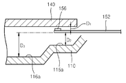
FIG. 5 is a cross-sectional view of gaps between the actuator arm 152, the disk 140, and the two- step recesses 115 and 116 according to an embodiment of the inventive concept. FIG. 6 is a top view of relative positions and sizes of the disk 140, the actuator 150, the two- step recesses 115 and 116, the extended shroud 117, and the air block 118 according to an embodiment of the inventive concept.
Referring to FIG. 5, a gap D1 between the disk 140 and the actuator arm 152 may be approximately between 0.8˜0.9 mm, for example, in a HDD employing the disk 140 of 3.5 inches. A gap D2 between the actuator arm 152 and the floor surface 115 a of the first step recess 115 is designed to be greater 3 times the gap D1. A gap D3 between the actuator arm 152 and the floor surface 116 a of the second step recess 116 is designed to be greater 6 times the gap D1.
Referring to FIG. 6, in a HDD employing the disk 140 of 3.5 inches, as described above, the extended shroud 117 may extend to the start point of the side surface 115 b of the upstream side of the first step recess 115. A line 171 that connects an end portion of the extended shroud 117 and a rotation center of the spindle motor 130 and a center line 172 in a length direction of the actuator arm 152 when a read/write head is positioned in the innermost side of the record region 144 of the disk 140 may be parallel to each other. A width G in a circumferential direction of the disk 140 of the floor surface 115 a of the first step recess 115 may be greater than approximately 10 mm. The read/write head may be positioned in a center line of the floor surface 115 a of the first step recess 115.
When a gap H between the air block 118 and an edge of the disk 140 is between 2.5˜3.5 mm, a reduction effect of the PES may further increase in the exterior edge region of the disk 140. An upstream end portion 118 a of the air block 118 may be identical to or be upper than an end point of the floor surface 116 a of the second step recess 116. A downstream end portion 118 b of the air block 118 may be identical to or be lower than an end point of the floor surface 115 a of the first step recess 115. A length J of the air block 118 may be greater 1.5 times the width G in the circumferential direction of the disk 140 of the floor surface 115 a of the first step recess 115.
A result of measuring a PES is listed in Table 1 below when the HDD including the base member 110 designed as above and employing the disk 140 of 3.5 inches operates.
TABLE 1
Two-Step Extended Air Average
Types Recesses Shroud Block PES
Case 1 X X 12.9
Case 2 X 13.0
Case 3 X 12.1
Case 4 10.85
An average PES is approximately 13 and 14 in a HDD including a conventional base member in which two-step recesses are not formed.
However, as listed in Table 1 above, all the average PES is below 13 in the cases 1 through 4 in which the two- step recesses 115 and 116 are informed in the base member 110. In particular, the average PES is 10. 85 in the case 4 in which the second step recess 116, the extended shroud 117, and the air block 118 are formed in the base member 110, which shows that the PES is much improved.
FIG. 7 is an exploded perspective view of a HDD according to another embodiment of the inventive concept.
Referring to FIG. 7, the disk 140 is fixed to the spindle motor 130 of the HDD by the disk clamp 110. The actuator 150 includes two actuator arms 152 a and 152 b that are rotatably combined to the actuator pivot 151 installed in the base member 110. The head gimbal assembly 154 is combined to the leading end portion of each of the actuator arms 152 a and 152 b and supporting the slider 156 on which read/write heads are mounted to be elastically biased toward a surface of the disk 140. The lower actuator arm 152 b is disposed below the disk 140. The read/write head that is combined to the lower actuator arm 152 b records data onto a lower surface of the disk 140 or reads the recorded data. The upper actuator arm 152 a is disposed above the disk 140. The read/write head that is combined to the upper actuator arm 152 a records data onto an upper surface of the disk 140 or reads the recorded data.
The base member 110 shown in FIG. 2 may be applied to the HDD that employs the two actuator arms 152 a and 152 b and the two read/write heads and uses the lower and upper surfaces of the disk 140. In addition to the base member 110 of FIG. 7, the two- step recesses 115 and 116, the extended shroud 117, and the air block 118 may be formed in the HDD.
A disk damper 160 may be disposed in an upper portion of the disk 140 in order to reduce vibration of the disk 140 caused by an air flow. The disk damper 160 is fixed to and supported by the base member 110 and has a shape facing a part of the upper surface of the disk 140.
The disk damper 160 may also be applied to the HDD shown in FIG. 1.
While the inventive concept has been particularly shown and described with reference to exemplary embodiments thereof, it will be understood that various changes in form and details may be made therein without departing from the spirit and scope of the following claims.

Claims (17)

1. An apparatus comprising:
a base supporting a disk;
a base floor surface disposed on the base in a region facing the disk;
a first step recess disposed on the base floor surface and comprising a first step recess floor; and
a second step recess disposed on the first step recess floor comprising a second step recess floor, wherein side surfaces of the first step recess and the second step recess are inclined.
2. The apparatus of claim 1, wherein the first step recess comprises an actuator pivot for rotatably supporting an actuator.
3. The apparatus of claim 1, further comprising:
a first shroud disposed on a circumference of the base floor surface and extending along an exterior circumference of the disk;
an actuator supported by the base; and
an extended shroud disposed in an upstream side of an operating region of the actuator, wherein the extended shroud protrudes from the first shroud and extends along the exterior circumference of the disk.
4. The apparatus of claim 3, wherein the extended shroud extends to a start point of an upstream side surface of the first step recess.
5. The apparatus of claim 1, further comprising an air block disposed on the second step recess floor, wherein the air block is disposed in a downstream side of an operating region of an actuator supported by the base.
6. The apparatus of claim 1, further comprising an air block disposed on the second step recess floor, wherein the air block is disposed in a position corresponding to a downstream side surface of the second step recess and the first step recess floor connected to the downstream side surface of the second step recess.
7. The apparatus of claim 1, further comprising an air block disposed on the second step recess floor, wherein the air block is spaced apart from an exterior circumference of the disk by 2.5 and 3.5 mm.
8. An apparatus comprising:
a base member supporting a data storage disk;
a first floor surface disposed on the base in a region facing the disk;
a first shroud disposed on a circumference of the first floor surface and extending along an exterior circumference of the disk; and
two-step recesses comprising a first step recess disposed on the first floor surface and a second step recess disposed on a first step floor surface of the first step recess, wherein side surfaces of the first step recess and the second step recess are inclined.
9. The apparatus of claim 8, wherein the base member further comprises a second floor surface comprising an actuator pivot for rotatably supporting an actuator, wherein the second floor surface is on the same plane as the second step floor surface of the second step recess.
10. The apparatus of claim 8, further comprising:
an actuator supported by the base member; and
an extended shroud disposed in an upstream side of an operating region of the actuator of the base member, wherein the extended shroud protrudes from the first shroud and extends along the exterior circumference of the disk.
11. The apparatus of claim 10, wherein the extended shroud extends to a start point of an upstream side surface of the first step recess.
12. The apparatus of claim 8, further comprising an air block disposed in a second step floor surface of the second step recess, wherein the air block is disposed in a downstream side of an operating region of an actuator supported by the base member.
13. The apparatus of claim 8, further comprising an air block disposed in a second step floor surface of the second step recess, wherein the air block is disposed in a position corresponding to a downstream side surface of the second step recess and first step floor surface of the first step recess connected to the downstream side surface of the second step recess.
14. The apparatus of claim 8, further comprising an air block disposed in a second step floor surface of the second step recess, wherein the air block is spaced apart from the exterior circumference of the disk by 2.5 and 3.5 mm.
15. The apparatus of claim 8, further comprising an actuator supported by the base member, wherein the actuator comprises:
an actuator arm operable to operate below the disk;
a head gimbal assembly disposed on a leading end portion of the actuator arm and supporting a read/write head, wherein the head is elastically biased toward a lower surface of the disk; and
a voice coil motor operable to rotate the actuator arm.
16. The apparatus of claim 8, further comprising an actuator supported by the base member, wherein the actuator comprises:
a lower actuator arm disposed to operate below the disk;
an upper actuator arm disposed to operate above the disk;
head gimbal assemblies disposed on leading end portions of the lower actuator arm and the upper actuator arm, wherein the head gimbal assemblies support read/write heads and are operable to elastically bias the read/write heads toward lower and upper surfaces of the disk; and
a voice coil motor operable to rotate the lower actuator arm and the upper actuator arm.
17. The apparatus of claim 8, further comprising a disk damper disposed on an upper portion of the disk and supported by the base member.
US12/908,556 2010-02-05 2010-10-20 Two-step recess base Expired - Fee Related US8339730B2 (en)

Applications Claiming Priority (3)

Application Number Priority Date Filing Date Title
KR10-2010-0011184 2010-02-05
KR2010-11184 2010-02-05
KR1020100011184A KR20110091376A (en) 2010-02-05 2010-02-05 Base member with two-step recesses and hard disk drive having the same

Publications (2)

Publication Number Publication Date
US20110194212A1 US20110194212A1 (en) 2011-08-11
US8339730B2 true US8339730B2 (en) 2012-12-25

Family

ID=44353541

Family Applications (1)

Application Number Title Priority Date Filing Date
US12/908,556 Expired - Fee Related US8339730B2 (en) 2010-02-05 2010-10-20 Two-step recess base

Country Status (3)

Country Link
US (1) US8339730B2 (en)
KR (1) KR20110091376A (en)
CN (1) CN102148040B (en)

Cited By (2)

* Cited by examiner, † Cited by third party
Publication number Priority date Publication date Assignee Title
US20110202938A1 (en) * 2010-02-12 2011-08-18 Funai Electric Co., Ltd. Disk Device
US10056117B1 (en) * 2017-05-11 2018-08-21 Western Digital Technologies, Inc. Data storage device baseplate diverter and downstream spoiler

Families Citing this family (2)

* Cited by examiner, † Cited by third party
Publication number Priority date Publication date Assignee Title
KR101858059B1 (en) * 2011-08-17 2018-06-29 페어차일드코리아반도체 주식회사 Switch control circuit, power factor corrector comprising the same, and driving mehtod of the power factor corrector
US9147436B2 (en) * 2012-04-25 2015-09-29 Western Digital Technologies, Inc. Slim form factor disk drive comprising disk drive enclosure having an insular raised region

Citations (12)

* Cited by examiner, † Cited by third party
Publication number Priority date Publication date Assignee Title
JPH11232866A (en) 1998-02-13 1999-08-27 Hitachi Ltd Magnetic disk device
KR20030031841A (en) 2001-10-16 2003-04-23 삼성전자주식회사 The hard disk assembly
KR20030068261A (en) 2002-02-14 2003-08-21 삼성전자주식회사 Hard disk drive having air pumping groove
KR100450673B1 (en) 2001-03-01 2004-10-01 삼성전자주식회사 Removing method of contaminent on a disk, housing and disk assembly of hard disk drive adopting the method
US7307811B2 (en) * 2005-02-04 2007-12-11 Seagate Technology Llc Disc storage system deck with integrally formed snubbers
US7379265B2 (en) * 2002-01-24 2008-05-27 Seagate Technology Llc Disc drive air borne filtering channel
US7535671B2 (en) * 2004-12-24 2009-05-19 Hitachi Global Storage Technologies Netherlands B.V. Disk drive with airflow control and fins at a transition surface between base surfaces
US7573671B2 (en) * 2004-12-22 2009-08-11 Hitachi Global Storage Technologies Netherlands B.V. Disk device with reduced flutter
US7751145B1 (en) * 2007-01-12 2010-07-06 Western Digital Technologies, Inc. Disk drive with air channel
US7898764B2 (en) * 2006-10-19 2011-03-01 Hitachi Global Storage Technologies Netherlands B.V. System, method, and apparatus for slit shroud with integrated bypass channel wall feature for disk drive applications
US8009384B1 (en) * 2008-09-30 2011-08-30 Western Digital Technologies, Inc. Cast baseplate for a disk drive having an arcuate shroud wall and adjacent arcuate groove
US8059364B1 (en) * 2004-05-04 2011-11-15 Maxtor Corporation Hermetically sealed connector interface

Family Cites Families (3)

* Cited by examiner, † Cited by third party
Publication number Priority date Publication date Assignee Title
US20060146448A1 (en) * 2004-12-30 2006-07-06 Gregory Tran Method and apparatus for an actuator arm block including a crash stop stub in a hard disk drive
JP4309417B2 (en) * 2006-10-05 2009-08-05 株式会社東芝 Disk unit
CN101471122A (en) * 2007-12-27 2009-07-01 株式会社东芝 Disk drive apparatus

Patent Citations (12)

* Cited by examiner, † Cited by third party
Publication number Priority date Publication date Assignee Title
JPH11232866A (en) 1998-02-13 1999-08-27 Hitachi Ltd Magnetic disk device
KR100450673B1 (en) 2001-03-01 2004-10-01 삼성전자주식회사 Removing method of contaminent on a disk, housing and disk assembly of hard disk drive adopting the method
KR20030031841A (en) 2001-10-16 2003-04-23 삼성전자주식회사 The hard disk assembly
US7379265B2 (en) * 2002-01-24 2008-05-27 Seagate Technology Llc Disc drive air borne filtering channel
KR20030068261A (en) 2002-02-14 2003-08-21 삼성전자주식회사 Hard disk drive having air pumping groove
US8059364B1 (en) * 2004-05-04 2011-11-15 Maxtor Corporation Hermetically sealed connector interface
US7573671B2 (en) * 2004-12-22 2009-08-11 Hitachi Global Storage Technologies Netherlands B.V. Disk device with reduced flutter
US7535671B2 (en) * 2004-12-24 2009-05-19 Hitachi Global Storage Technologies Netherlands B.V. Disk drive with airflow control and fins at a transition surface between base surfaces
US7307811B2 (en) * 2005-02-04 2007-12-11 Seagate Technology Llc Disc storage system deck with integrally formed snubbers
US7898764B2 (en) * 2006-10-19 2011-03-01 Hitachi Global Storage Technologies Netherlands B.V. System, method, and apparatus for slit shroud with integrated bypass channel wall feature for disk drive applications
US7751145B1 (en) * 2007-01-12 2010-07-06 Western Digital Technologies, Inc. Disk drive with air channel
US8009384B1 (en) * 2008-09-30 2011-08-30 Western Digital Technologies, Inc. Cast baseplate for a disk drive having an arcuate shroud wall and adjacent arcuate groove

Cited By (2)

* Cited by examiner, † Cited by third party
Publication number Priority date Publication date Assignee Title
US20110202938A1 (en) * 2010-02-12 2011-08-18 Funai Electric Co., Ltd. Disk Device
US10056117B1 (en) * 2017-05-11 2018-08-21 Western Digital Technologies, Inc. Data storage device baseplate diverter and downstream spoiler

Also Published As

Publication number Publication date
KR20110091376A (en) 2011-08-11
CN102148040A (en) 2011-08-10
CN102148040B (en) 2015-03-04
US20110194212A1 (en) 2011-08-11

Similar Documents

Publication Publication Date Title
US7474500B2 (en) Hard disk having air guide
US7453667B2 (en) Hard disk drive, hard disk damper, and method for the same
US20090067086A1 (en) Storage device
JP4476970B2 (en) Head, head suspension assembly, and disk device including the same
US8264794B2 (en) Head and disk drive with same
JP4170075B2 (en) Recording medium driving device
US8339730B2 (en) Two-step recess base
US7573672B2 (en) Cover member with air guiding portion and hard disk drive including the cover member
JP2006172699A (en) Head parking ramp for hard disk drive and hard disk drive with the same
JP4202939B2 (en) Recording disk drive device and ramp member
US20050264928A1 (en) Disk spacer and spindle motor assembly employing the same
US20090168234A1 (en) Disk drive apparatus
US20060209456A1 (en) Disk drive apparatus
JP4074265B2 (en) Head suspension assembly and disk drive equipped with the same
US8526140B2 (en) Reverse flow preventer unit
US8259418B2 (en) Head suspension assembly and disk device with the same
US7821741B2 (en) Disk drive head stack assembly interacting with movement guide for preventing head from contacting the disk during read/write operations
JP2006185485A (en) Disk drive unit
JP2007280517A (en) Disk-driving device and ramp
US20120162816A1 (en) Airflow shroud that reduces vibration of a rotating disk in a hard disk drive
US8711513B1 (en) Disk drive
JP4234634B2 (en) Magnetic disk unit
KR100699903B1 (en) Disk damper, Hard disk drive including the disk damper and Fabricating method of the disk damper
JP2004234804A (en) Disk device and head suspension assembly
JP2007164870A (en) Disk driver

Legal Events

Date Code Title Description
AS Assignment

Owner name: SAMSUNG ELECTRONICS CO., LTD., KOREA, REPUBLIC OF

Free format text: ASSIGNMENT OF ASSIGNORS INTEREST;ASSIGNORS:LIM, HONG-TAEK;SONG, YONG-HAN;KIM, SUNG-WOOK;REEL/FRAME:025168/0350

Effective date: 20101012

AS Assignment

Owner name: SEAGATE TECHNOLOGY INTERNATIONAL, CAYMAN ISLANDS

Free format text: ASSIGNMENT OF ASSIGNORS INTEREST;ASSIGNOR:SAMSUNG ELECTRONICS CO., LTD.;REEL/FRAME:027774/0340

Effective date: 20111219

AS Assignment

Owner name: SEAGATE TECHNOLOGY INTERNATIONAL, CAYMAN ISLANDS

Free format text: ASSIGNMENT OF ASSIGNORS INTEREST;ASSIGNOR:SAMSUNG ELECTRONICS CO., LTD.;REEL/FRAME:027905/0581

Effective date: 20111219

REMI Maintenance fee reminder mailed
LAPS Lapse for failure to pay maintenance fees
STCH Information on status: patent discontinuation

Free format text: PATENT EXPIRED DUE TO NONPAYMENT OF MAINTENANCE FEES UNDER 37 CFR 1.362

FP Lapsed due to failure to pay maintenance fee

Effective date: 20161225