EP1566708A2 - Aufzugsvorrichtung für Uhren - Google Patents
Aufzugsvorrichtung für Uhren Download PDFInfo
- Publication number
- EP1566708A2 EP1566708A2 EP04405781A EP04405781A EP1566708A2 EP 1566708 A2 EP1566708 A2 EP 1566708A2 EP 04405781 A EP04405781 A EP 04405781A EP 04405781 A EP04405781 A EP 04405781A EP 1566708 A2 EP1566708 A2 EP 1566708A2
- Authority
- EP
- European Patent Office
- Prior art keywords
- ring
- tube
- disc
- winding
- recesses
- Prior art date
- Legal status (The legal status is an assumption and is not a legal conclusion. Google has not performed a legal analysis and makes no representation as to the accuracy of the status listed.)
- Granted
Links
- 238000004804 winding Methods 0.000 title claims abstract description 31
- 238000007789 sealing Methods 0.000 claims abstract description 6
- 238000004026 adhesive bonding Methods 0.000 claims description 2
- 210000000056 organ Anatomy 0.000 claims description 2
- 230000007246 mechanism Effects 0.000 description 3
- 101100536354 Drosophila melanogaster tant gene Proteins 0.000 description 1
- 240000008042 Zea mays Species 0.000 description 1
- 230000000295 complement effect Effects 0.000 description 1
- 239000000470 constituent Substances 0.000 description 1
- 238000010276 construction Methods 0.000 description 1
- 230000008878 coupling Effects 0.000 description 1
- 238000010168 coupling process Methods 0.000 description 1
- 238000005859 coupling reaction Methods 0.000 description 1
- 239000012535 impurity Substances 0.000 description 1
- 239000007788 liquid Substances 0.000 description 1
- 230000007774 longterm Effects 0.000 description 1
- 230000003647 oxidation Effects 0.000 description 1
- 238000007254 oxidation reaction Methods 0.000 description 1
- 238000010079 rubber tapping Methods 0.000 description 1
- XLYOFNOQVPJJNP-UHFFFAOYSA-N water Substances O XLYOFNOQVPJJNP-UHFFFAOYSA-N 0.000 description 1
Images


Classifications
-
- G—PHYSICS
- G04—HOROLOGY
- G04B—MECHANICALLY-DRIVEN CLOCKS OR WATCHES; MECHANICAL PARTS OF CLOCKS OR WATCHES IN GENERAL; TIME PIECES USING THE POSITION OF THE SUN, MOON OR STARS
- G04B3/00—Normal winding of clockworks by hand or mechanically; Winding up several mainsprings or driving weights simultaneously
- G04B3/06—Keys or the like with means preventing overwinding
Definitions
- the present invention relates to the field of mechanical watchmaking. She more particularly, a winding device comprising a crown of the type mounted at the end of a winding stem.
- the rod ensures, in particular, the armature function of the mainspring of a mechanical watch with manual winding. In its middle part, it is kinematically connected to a winding pinion which, via a gear train, drives the mainspring. At its outer end, the rod is fixed, often by screwing, to the winding crown.
- the US Patent 2,571,879 discloses a mechanism comprising a spring and balls, arranged to produce a clutch and generate a clatter warning when the carrier raises the spring excessively. This solution makes it possible, of course, to limit the arming of the spring, but it does not guarantee in the long term, satisfactory operating conditions, because of a significant risk of clogging the mechanism.
- the document FR 1 230 864 proposes to insert between the crown and the spring, a limited torque coupling member having a very low friction, housed inside the movement.
- This friction can be modulated by means of a spring which can be adjusted tension by means of a nut.
- Such a solution occupies a volume considerable inside the movement and requires adjustments delicate, likely to go wrong.
- the main object of the present invention is to provide a winding device particularly simple and easy to produce and to avoid any over-springing of the mainspring without taking up space inside the movement. Moreover, the device according to the invention also has for objective of good resistance to wear and damage caused by weather and Terms of use.
- the device further comprises a sealing member interposed between the crown and the tube, delimiting a confined space inside which is housed the disengaging member. In this way, it is protected from water and dirt that may come from the wearer's environment without to occupy space in the movement.
- the elastic member has an axial deformation when the torque is applied.
- the means of connection include hollows on the faces of the piece and clutch disc located opposite each other and balls positioned in the recesses. The engagement of the marbles in the hollows the shallower, disk or room, defines the arming of the organ elastic.
- connection means are formed of bosses and recesses, practiced on the piece clutch disk and the others on the clutch disc, these bosses being arranged to engage in the recesses.
- the elastic member consists of a coil spring interposed between the ring and the clutch disc. This solution takes up little space and allows a good control of the limit torque.
- the latter is constituted a sine circle interspersed between the ring and the clutch disc.
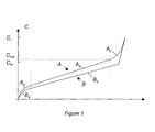
- Figure 1 shows the typical winding A and disarming curves B of a mainspring, with the number of armature turns on the abscissa and the pair on the ordinate. If one starts from the point 0, we see that, in a first zone A has, the torque increases rapidly, the slope tapering. In this area, the barrel spring begins to wind on its shaft. In zone A b , the torque increases substantially linearly. The barrel spring flexes and coils progressively on the shaft, until the armature reaches a limit value C lim . If the arming continues, the torque then increases strongly again, as can be seen in the area A c , the spring being subjected to traction. If the applied torque exceeds a limit value C r , the spring may break.
- the torque applied by the mainspring on the wheel of the watch is slightly lower than the armature torque, because of friction losses.
- the decay of the torque is substantially linear, whereas in zone B a , it decays in a quadratic way, to find the point 0.
- the disarming curve does not have an area equivalent to the zone A c , it is because the arming of the spring is guaranteed by a pawl which has a sufficient back to find the linear zone.
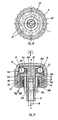
- FIGS. 2a and 2b show a first variant of a device 10 of winding torque limiting according to the invention, respectively seen in section axial and in plan. It is intended to equip a watch equipped with a box provided with a tube 12, visible only in FIG. 2a, with which it cooperates. This tube 12 is intended to ensure a connection between the interior and the outside of the box, in particular to carry out the winding operations and time setting.
- the clutch part 20 must be rest against the bottom 14a of the crown 14 and be able to rotate freely.
- the crown 14 and the piece 20 are therefore not permanently secured in rotation.
- the clutch disc 22 is disposed in the crown 14 so that it is integral in rotation, for example in defining an octagonal periphery of the disc 22, complementary in form to that presented by the housing 15 in its part between the staves 14d and 14th.
- he must be able to move axially so as to allow a disengagement between the piece 20 and the disc 22, as will be explained later.
- the assembly of the device as defined is done by placing in the housing 15 the plate 20a of the clutch part 20, its sleeve 20a being turned outward. It will be noted that the edge of the plate 20a is in its part adjoining the bottom 14a, so that a contact between the piece 20 and the crown 14 is only in the central part, to reduce friction.
- the balls 24 are put in place, one in each of the recesses 20d.
- the disc 22 is then engaged on the piece 20, the central opening 22a surrounding the sleeve 20a.
- the recesses 22b are arranged so as to what the balls 24 engage, the disk 22 is thus positioned radially and axially with reference to the part 20, and that can roll on this one, but without direct contact.
- the ring 26 is prepared by driving the ring 32 so as to what it defines a space in which can take place the joint 30. After introducing the spring 28 into the groove 26a, the ring thus mounted and driven into the housing 15 of the crown 14, until it stops against the litter 14d.
- the contact between the ring 26 and the wall of the crown 14 must to be perfect, so that no liquid can penetrate it. For guarantee this contact, it is possible to fix these parts to each other by hunting and collage.
- the seal 30 can be put in place on the 14, either before or after the mounting of the ring 26. It can, in Besides, be easily replaced during after-sales service.
- the rod 18 can then be screwed onto the sleeve 20b.
- it advantageously comprises two parallel dishes between them and oriented longitudinally, which allow to tighten the sleeve 20b and thus ensure a screwing bottom of the rod 18 in the threaded hole.
- the device 10 is then mounted in a watch movement, the rod 18 being engaged in the box by the tube 12 and cooperating with a pinion of winder which ensures the winding of a mainspring, in a conventional manner, by a simple rotation of the ring 14.
- the tube 12 and the seal 30 are dimensioned so that they are in close contact with each other the other. In this way, the housing 15 forms a confined space that is not open only towards the inside of the box.
- the rotational movement of the ring gear 14 is transmitted to the rod 18 by the disengaging member 16.
- the spring 28 is armed (ie compressed) and the balls 24 out of the recesses 20d, which are shallower than the recesses 22b, and roll in the raceway to move to the next recess. In this way, the disk 22 is disengaged from the part 20 and the winding of the mainspring can no longer be done.
- the torque C max is essentially defined by the characteristics of the spring 28 and by the distance between the bottom of the groove 26a and the bearing surface of the clutch disk 22. However, to ensure this distance, it is necessary that the ring 26 is perfectly positioned with reference to the disk 22, which can be achieved by defining tight tolerances between the bearing surface of the part 20 in the bottom of the cap 14 and the bearing 14d.
- This couple is also influenced by the friction of the different parts constituent parts of the device. That's why special attention must be brought to the surface states of the parts in contact with each other. Because the space is confined, it is possible to lubricate the surfaces by relative movement, so as to guarantee good working conditions.
- the user applies a force of traction on the crown 14, which arms the spring 28.
- the ring 26 takes support against the disk 22 on the side opposite to that comprising the recesses 22a.
- the balls 24 are put under pressure and transmit the force to the piece 20 which axially drives the rod 18 which tends to come out of the box for take a position in which it is possible to perform a time.
- This operation is done by a rotation of the crown 14. It is obvious that, to be able to perform it without problem, the couple to apply to drive the gear and the mechanisms of the watch must be less than Cmax.
- the essential difference lies in that the seal 30 is housed in a groove 12a that comprises the tube 12. In this way, the structure of the ring 26 is simplified.
- FIG. 4 shows a variant requiring a volume substantially reduced by the fact that the spring 28 is replaced by a retaining ring 34 and two spring rings 38 and 40, also called circle sinus. These pieces together form an assembly that ensures the pressure of the clutch plate 22 against the clutch part 20, via 24.
- the ring 26 has an annular groove 26c to radial orientation in which is housed the seal 30 which is, here, formed of a single toric piece.
- the variants of Figures 5 and 6 do not include a ball.
- the room clutch 20 cooperates directly with the clutch disc 22, this last being provided with spherical bosses 22c engaged in the recesses 20d of the clutch part 20 for the variant of FIG. 5, whereas in the variant of FIG. 6, they are bosses 22d with radial orientation and trapezoidal section cooperating with the recesses 20d.
- the shape of these The latter is, of course, adapted to that of the bosses 22d.
Landscapes
- Physics & Mathematics (AREA)
- General Physics & Mathematics (AREA)
- Mechanical Operated Clutches (AREA)
- Transmission Devices (AREA)
- Springs (AREA)
Applications Claiming Priority (2)
| Application Number | Priority Date | Filing Date | Title |
|---|---|---|---|
| CH1112004 | 2004-01-28 | ||
| CH1112004A CH697270B1 (fr) | 2004-01-28 | 2004-01-28 | Dispositif de remontoir. |
Publications (3)
| Publication Number | Publication Date |
|---|---|
| EP1566708A2 true EP1566708A2 (de) | 2005-08-24 |
| EP1566708A3 EP1566708A3 (de) | 2008-03-05 |
| EP1566708B1 EP1566708B1 (de) | 2011-08-31 |
Family
ID=34706027
Family Applications (1)
| Application Number | Title | Priority Date | Filing Date |
|---|---|---|---|
| EP20040405781 Expired - Lifetime EP1566708B1 (de) | 2004-01-28 | 2004-12-17 | Aufzugsvorrichtung |
Country Status (2)
| Country | Link |
|---|---|
| EP (1) | EP1566708B1 (de) |
| CH (1) | CH697270B1 (de) |
Cited By (3)
| Publication number | Priority date | Publication date | Assignee | Title |
|---|---|---|---|---|
| EP2367075A1 (de) * | 2010-03-17 | 2011-09-21 | Meco S.A. | Aufzugskrone für Uhren |
| CN102385301A (zh) * | 2010-08-30 | 2012-03-21 | 深圳市飞亚达科技发展有限公司 | 一种手表上条过载保护机构及具有该保护机构的手表 |
| EP4692955A1 (de) * | 2024-08-05 | 2026-02-11 | Patek Philippe Sa Geneve | Aufzugskrone mit drehmomentbegrenzung |
Families Citing this family (1)
| Publication number | Priority date | Publication date | Assignee | Title |
|---|---|---|---|---|
| CH709363A1 (fr) * | 2014-03-19 | 2015-09-30 | Mps Micro Prec Systems Ag | Couronne de remontage. |
Citations (2)
| Publication number | Priority date | Publication date | Assignee | Title |
|---|---|---|---|---|
| US2571879A (en) | 1946-07-25 | 1951-10-16 | Hil Jon Safety Crown Corp | Overload release coupling |
| FR1230864A (fr) | 1958-07-24 | 1960-09-20 | Heliowatt Werke Elek Zitats Ag | Pendule ou horloge électrique à réserve de mouvement |
Family Cites Families (5)
| Publication number | Priority date | Publication date | Assignee | Title |
|---|---|---|---|---|
| GB604034A (en) * | 1944-11-27 | 1948-06-28 | Charles Hill | Improvements in watch winding device |
| US2716875A (en) * | 1953-03-20 | 1955-09-06 | Hill Charles | Watch winding means |
| DE945320C (de) * | 1953-08-20 | 1956-07-05 | Richard Pfisterer Fa | Krone fuer Armband- oder Taschenuhren |
| US2927420A (en) * | 1958-04-21 | 1960-03-08 | Hil Jon Safety Crown Corp | Waterproof watch winding means |
| CH696823A5 (fr) * | 2003-09-01 | 2007-12-14 | Patek Philippe Sa | Couronne de remontage pour pièce d'horlogerie mécanique. |
-
2004
- 2004-01-28 CH CH1112004A patent/CH697270B1/fr unknown
- 2004-12-17 EP EP20040405781 patent/EP1566708B1/de not_active Expired - Lifetime
Patent Citations (2)
| Publication number | Priority date | Publication date | Assignee | Title |
|---|---|---|---|---|
| US2571879A (en) | 1946-07-25 | 1951-10-16 | Hil Jon Safety Crown Corp | Overload release coupling |
| FR1230864A (fr) | 1958-07-24 | 1960-09-20 | Heliowatt Werke Elek Zitats Ag | Pendule ou horloge électrique à réserve de mouvement |
Cited By (4)
| Publication number | Priority date | Publication date | Assignee | Title |
|---|---|---|---|---|
| EP2367075A1 (de) * | 2010-03-17 | 2011-09-21 | Meco S.A. | Aufzugskrone für Uhren |
| US8602639B2 (en) | 2010-03-17 | 2013-12-10 | Meco S.A. | Winding crown for a timepiece |
| CN102385301A (zh) * | 2010-08-30 | 2012-03-21 | 深圳市飞亚达科技发展有限公司 | 一种手表上条过载保护机构及具有该保护机构的手表 |
| EP4692955A1 (de) * | 2024-08-05 | 2026-02-11 | Patek Philippe Sa Geneve | Aufzugskrone mit drehmomentbegrenzung |
Also Published As
| Publication number | Publication date |
|---|---|
| EP1566708A3 (de) | 2008-03-05 |
| CH697270B1 (fr) | 2008-07-31 |
| EP1566708B1 (de) | 2011-08-31 |
Similar Documents
| Publication | Publication Date | Title |
|---|---|---|
| EP0121497B1 (de) | Linearbetätiger mit einem elektrischen Motor | |
| FR2728637A1 (fr) | Embrayage a friction a ressort auxiliaire destine a realiser une assistance pour la force de debrayage | |
| FR3004771A1 (fr) | Transmission pour engin roulant a conducteur marchant, et engin roulant equipe d'une telle transmission | |
| EP1586960A1 (de) | Krone für eine Uhr mit einer Auskupplungsvorrichtung | |
| WO2003083243A9 (fr) | Mecanisme de tension d'un ressort de compensation pour installation de fermeture ou de protection solaire | |
| EP1857892A1 (de) | Uhr mit einem drehbaren Teil | |
| EP0892944B1 (de) | Uhr | |
| EP1566708B1 (de) | Aufzugsvorrichtung | |
| FR2799800A1 (fr) | Demarreur | |
| EP1853977B1 (de) | Blockierbarer drücker | |
| EP1087096A1 (de) | Betätigungseinrichtung einer Entkupplungsvorrichtung für einen Getriebemotorantrieb einer Schliess- oder Sonnenschutzeinrichtung | |
| EP3379105A1 (de) | Zahnradgetriebeelement mit rollen | |
| FR2587781A1 (fr) | Clapet d'arret dont l'etancheite du clapet est independante du sens d'action de la pression differentielle | |
| EP1676176A1 (de) | Steuerungseinrichtung mit ausklinkbarer krone für eine armbanduhr | |
| FR3082891A1 (fr) | Demarreur comprenant une couronne de reducteur calee axialement | |
| EP3492995A1 (de) | Kranzsystem für uhr | |
| CH703671B1 (fr) | Couronne à visser et procédé de vissage d'une telle couronne. | |
| FR2587965A1 (fr) | Manivelle pour pedalier de bicyclette | |
| CH330891A (fr) | Dispositif à roue libre de petites dimensions | |
| FR2923879A1 (fr) | Dispositif de couplage par cone de friction pour boite de vitesses. | |
| EP3654109B1 (de) | Uhr, die zwei energiequellen besitzt | |
| FR3140413A1 (fr) | Boîte de vitesses d’un véhicule automobile | |
| CH713583B1 (fr) | Mécanisme de remontage d'une pièce d'horlogerie. | |
| FR2689256A1 (fr) | Couronne de montre. | |
| FR2516998A1 (fr) | Dispositif a montage perfectionne pour la commande de desengagement d'un embrayage, notamment de vehicule automobile |
Legal Events
| Date | Code | Title | Description |
|---|---|---|---|
| PUAI | Public reference made under article 153(3) epc to a published international application that has entered the european phase |
Free format text: ORIGINAL CODE: 0009012 |
|
| AK | Designated contracting states |
Kind code of ref document: A2 Designated state(s): AT BE BG CH CY CZ DE DK EE ES FI FR GB GR HU IE IS IT LI LT LU MC NL PL PT RO SE SI SK TR |
|
| AX | Request for extension of the european patent |
Extension state: AL BA HR LV MK YU |
|
| PUAL | Search report despatched |
Free format text: ORIGINAL CODE: 0009013 |
|
| AK | Designated contracting states |
Kind code of ref document: A3 Designated state(s): AT BE BG CH CY CZ DE DK EE ES FI FR GB GR HU IE IS IT LI LT LU MC NL PL PT RO SE SI SK TR |
|
| AX | Request for extension of the european patent |
Extension state: AL BA HR LV MK YU |
|
| RTI1 | Title (correction) |
Free format text: WINDING DEVICE |
|
| 17P | Request for examination filed |
Effective date: 20080905 |
|
| AKX | Designation fees paid |
Designated state(s): CH DE FR GB IT LI |
|
| GRAP | Despatch of communication of intention to grant a patent |
Free format text: ORIGINAL CODE: EPIDOSNIGR1 |
|
| GRAS | Grant fee paid |
Free format text: ORIGINAL CODE: EPIDOSNIGR3 |
|
| GRAA | (expected) grant |
Free format text: ORIGINAL CODE: 0009210 |
|
| AK | Designated contracting states |
Kind code of ref document: B1 Designated state(s): CH DE FR GB IT LI |
|
| REG | Reference to a national code |
Ref country code: GB Ref legal event code: FG4D Free format text: NOT ENGLISH Ref country code: CH Ref legal event code: EP |
|
| REG | Reference to a national code |
Ref country code: DE Ref legal event code: R096 Ref document number: 602004034200 Country of ref document: DE Effective date: 20111103 |
|
| REG | Reference to a national code |
Ref country code: CH Ref legal event code: NV Representative=s name: GLN S.A. |
|
| PG25 | Lapsed in a contracting state [announced via postgrant information from national office to epo] |
Ref country code: IT Free format text: LAPSE BECAUSE OF FAILURE TO SUBMIT A TRANSLATION OF THE DESCRIPTION OR TO PAY THE FEE WITHIN THE PRESCRIBED TIME-LIMIT Effective date: 20110831 |
|
| PLBE | No opposition filed within time limit |
Free format text: ORIGINAL CODE: 0009261 |
|
| STAA | Information on the status of an ep patent application or granted ep patent |
Free format text: STATUS: NO OPPOSITION FILED WITHIN TIME LIMIT |
|
| 26N | No opposition filed |
Effective date: 20120601 |
|
| GBPC | Gb: european patent ceased through non-payment of renewal fee |
Effective date: 20111217 |
|
| REG | Reference to a national code |
Ref country code: DE Ref legal event code: R097 Ref document number: 602004034200 Country of ref document: DE Effective date: 20120601 |
|
| PG25 | Lapsed in a contracting state [announced via postgrant information from national office to epo] |
Ref country code: GB Free format text: LAPSE BECAUSE OF NON-PAYMENT OF DUE FEES Effective date: 20111217 |
|
| REG | Reference to a national code |
Ref country code: CH Ref legal event code: PCAR Free format text: NEW ADDRESS: AVENUE EDOUARD-DUBOIS 20, 2000 NEUCHATEL (CH) |
|
| REG | Reference to a national code |
Ref country code: FR Ref legal event code: PLFP Year of fee payment: 12 |
|
| REG | Reference to a national code |
Ref country code: CH Ref legal event code: PFA Owner name: RICHEMONT INTERNATIONAL S.A., CH Free format text: FORMER OWNER: RICHEMONT INTERNATIONAL S.A., CH |
|
| REG | Reference to a national code |
Ref country code: FR Ref legal event code: PLFP Year of fee payment: 13 |
|
| REG | Reference to a national code |
Ref country code: FR Ref legal event code: PLFP Year of fee payment: 14 |
|
| PGFP | Annual fee paid to national office [announced via postgrant information from national office to epo] |
Ref country code: DE Payment date: 20181210 Year of fee payment: 15 |
|
| PGFP | Annual fee paid to national office [announced via postgrant information from national office to epo] |
Ref country code: FR Payment date: 20181127 Year of fee payment: 17 |
|
| REG | Reference to a national code |
Ref country code: CH Ref legal event code: NV Representative=s name: BOVARD SA NEUCHATEL CONSEILS EN PROPRIETE INTE, CH |
|
| REG | Reference to a national code |
Ref country code: DE Ref legal event code: R119 Ref document number: 602004034200 Country of ref document: DE |
|
| PG25 | Lapsed in a contracting state [announced via postgrant information from national office to epo] |
Ref country code: DE Free format text: LAPSE BECAUSE OF NON-PAYMENT OF DUE FEES Effective date: 20200701 Ref country code: FR Free format text: LAPSE BECAUSE OF NON-PAYMENT OF DUE FEES Effective date: 20191231 |
|
| PGFP | Annual fee paid to national office [announced via postgrant information from national office to epo] |
Ref country code: CH Payment date: 20240101 Year of fee payment: 20 |
|
| REG | Reference to a national code |
Ref country code: CH Ref legal event code: PL |