EP1566680A1 - Miniature zoom lens - Google Patents
Miniature zoom lens Download PDFInfo
- Publication number
- EP1566680A1 EP1566680A1 EP05003441A EP05003441A EP1566680A1 EP 1566680 A1 EP1566680 A1 EP 1566680A1 EP 05003441 A EP05003441 A EP 05003441A EP 05003441 A EP05003441 A EP 05003441A EP 1566680 A1 EP1566680 A1 EP 1566680A1
- Authority
- EP
- European Patent Office
- Prior art keywords
- lens
- lens group
- positive
- forming
- negative
- Prior art date
- Legal status (The legal status is an assumption and is not a legal conclusion. Google has not performed a legal analysis and makes no representation as to the accuracy of the status listed.)
- Granted
Links
- 230000003287 optical effect Effects 0.000 claims abstract description 13
- 230000014509 gene expression Effects 0.000 claims description 12
- 230000005499 meniscus Effects 0.000 claims description 9
- 230000004075 alteration Effects 0.000 description 13
- 201000009310 astigmatism Diseases 0.000 description 7
- 239000000463 material Substances 0.000 description 1
- 210000001747 pupil Anatomy 0.000 description 1
Images


Classifications
-
- G—PHYSICS
- G02—OPTICS
- G02B—OPTICAL ELEMENTS, SYSTEMS OR APPARATUS
- G02B15/00—Optical objectives with means for varying the magnification
- G02B15/14—Optical objectives with means for varying the magnification by axial movement of one or more lenses or groups of lenses relative to the image plane for continuously varying the equivalent focal length of the objective
- G02B15/143—Optical objectives with means for varying the magnification by axial movement of one or more lenses or groups of lenses relative to the image plane for continuously varying the equivalent focal length of the objective having three groups only
- G02B15/1435—Optical objectives with means for varying the magnification by axial movement of one or more lenses or groups of lenses relative to the image plane for continuously varying the equivalent focal length of the objective having three groups only the first group being negative
- G02B15/143507—Optical objectives with means for varying the magnification by axial movement of one or more lenses or groups of lenses relative to the image plane for continuously varying the equivalent focal length of the objective having three groups only the first group being negative arranged -++
-
- G—PHYSICS
- G02—OPTICS
- G02B—OPTICAL ELEMENTS, SYSTEMS OR APPARATUS
- G02B13/00—Optical objectives specially designed for the purposes specified below
- G02B13/001—Miniaturised objectives for electronic devices, e.g. portable telephones, webcams, PDAs, small digital cameras
- G02B13/0015—Miniaturised objectives for electronic devices, e.g. portable telephones, webcams, PDAs, small digital cameras characterised by the lens design
- G02B13/002—Miniaturised objectives for electronic devices, e.g. portable telephones, webcams, PDAs, small digital cameras characterised by the lens design having at least one aspherical surface
- G02B13/004—Miniaturised objectives for electronic devices, e.g. portable telephones, webcams, PDAs, small digital cameras characterised by the lens design having at least one aspherical surface having four lenses
-
- G—PHYSICS
- G02—OPTICS
- G02B—OPTICAL ELEMENTS, SYSTEMS OR APPARATUS
- G02B13/00—Optical objectives specially designed for the purposes specified below
- G02B13/001—Miniaturised objectives for electronic devices, e.g. portable telephones, webcams, PDAs, small digital cameras
- G02B13/009—Miniaturised objectives for electronic devices, e.g. portable telephones, webcams, PDAs, small digital cameras having zoom function
-
- G—PHYSICS
- G02—OPTICS
- G02B—OPTICAL ELEMENTS, SYSTEMS OR APPARATUS
- G02B3/00—Simple or compound lenses
- G02B3/0087—Simple or compound lenses with index gradient
-
- G—PHYSICS
- G02—OPTICS
- G02B—OPTICAL ELEMENTS, SYSTEMS OR APPARATUS
- G02B3/00—Simple or compound lenses
- G02B3/02—Simple or compound lenses with non-spherical faces
- G02B3/04—Simple or compound lenses with non-spherical faces with continuous faces that are rotationally symmetrical but deviate from a true sphere, e.g. so called "aspheric" lenses
-
- G—PHYSICS
- G02—OPTICS
- G02B—OPTICAL ELEMENTS, SYSTEMS OR APPARATUS
- G02B3/00—Simple or compound lenses
- G02B2003/0093—Simple or compound lenses characterised by the shape
Definitions
- the present invention relates to a miniature zoom lens for use in a digital camera or the like using a miniature solid-state image sensor and incorporated into a mobile phone or the like.
- a surveillance camera having a built-in digital video camera has been getting smaller in size.
- These cameras need a miniature optical system suitable for a miniature solid-state image sensor, and it is convenient when the miniature optical system is, preferably, a zoom lens of a structure such that can vary a focal length of the overall lens system continuously while keeping the image-forming position on the same plane.
- a three-component zoom lens which comprises, sequentially from the object side, a first lens group having negative refractive power, a second lens group having positive refractive power, and a third lens group having positive refractive power as has been disclosed, for example, in Patent Documents 1 through 4.
- the zoom lens disclosed in Patent Document 1 is of a simple configuration by forming each lens group from a single lens; however, it fails to attain a zoom ratio of two times and the performance as a zoom lens is therefore insufficient.
- the zoom lens disclosed in Patent Document 2 is for use in an electron still camera, and an interval between the first lens group and the second lens group is 13 mm or longer. Hence, this zoom lens is not small enough to be incorporated into a mobile phone or the like.
- the zoom lens disclosed in Patent Document 3 is of a relatively miniature size by forming each lens group from a single lens and attains a large zoom ratio; however, in order to attain a large zoom ratio, the first lens group and the second group have to move, which causes a total length to vary. This raises a problem that it is difficult to incorporate this zoom lens into a portable device.
- the zoom lens disclosed in Patent Document 4 is of a relatively miniature size by forming each of the first lens group and the third lens group from a single lens and the second lens group from two positive and negative lenses, and attains a large zoom ratio; however, because the first lens and the second lens have to move, this zoom lens also has a problem that a total length varies.
- the invention was devised in view of the foregoing, and therefore has an object to provide a high-performance miniature zoom lens of a simple configuration, capable of attaining a large zoom ratio while keeping a constant total length.
- a first aspect of the invention provides a miniature zoom lens, characterized by having, sequentially from an object side, a first lens group having negative refractive power, a second lens group having positive refractive power and including a diaphragm, and a third lens group having positive refractive power, wherein: the first lens group is formed from a single negative lens, the second lens group is formed from, sequentially from the object side, a single positive lens and a single negative lens, and the third lens group is formed from a single positive lens; and the first lens group is immovable and the second lens group and the third lens group move in an optical axis direction at variable power.
- the three-component zoom lens is of a simple configuration using four lenses in three groups, in which each of the first lens group and the third lens group is formed from a single lens, and the second lens group is formed from two lenses. Also, because the first lens group is immovable whereas the second lens group and the third lens group move, the total length will not vary. Further, by forming the first lens group from a single negative lens, the second lens group from two positive and negative lenses, and the third lens group from a single positive lens, it is possible to increase a zoom ratio while correcting aberration satisfactorily.
- a second aspect of the invention provides a miniature zoom lens according to the first aspect, wherein: the negative lens forming the first lens group is a meniscus lens having at least one aspherical surface and whose surface having a larger curvature faces the object side; the positive lens forming the second lens group includes at least one aspherical surface, and the negative lens forming the second lens group includes at least one aspherical surface; and the positive lens forming the third lens group is configured so that a surface having a larger curvature faces an image-forming surface side. According to the configuration as above, even when a zoom ratio is increased, it is still possible to correct aberration of various kinds satisfactorily.
- a third aspect of the invention provides a miniature zoom lens according to the first or second aspect, wherein: Conditional Expression (1) specified below is satisfied: 2.5 ⁇
- Conditional Expression (1) it is possible to reduce the zoom lens in size while not only can refractive power of the first lens group be set adequately, but also aberration of various kinds can be corrected satisfactorily.
- a fourth aspect of the invention provides a miniature zoom lens according to any of the first through third aspects, wherein: Conditional Expression (2) specified below is satisfied: 1.0 ⁇
- Conditional Expression (2) it is possible to reduce the zoom lens in size while not only can refractive power of the second lens group be set adequately, but also aberration of various kinds can be corrected satisfactorily.
- a fifth aspect of the invention provides a miniature zoom lens according to any of the first through fourth aspects, wherein: the positive lens forming the second lens group is a biconvex lens; the negative lens forming the second lens group is a negative meniscus lens; and the positive lens forming the third lens group is a positive meniscus lens. According to the configuration as above, even when a zoom ratio is increased, it is still possible to correct aberration of various kinds satisfactorily.
- FIG. 1 shows cross sections of lenses in an example of a miniature zoom lens of the invention.
- FIG. 2 shows locations of lens groups at variable power.
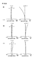
- FIG. 3 shows astigmatism charts and distortion charts in this example.
- a reference Ri (i is an integer from 1) indicates a serial lens surface number from the object side to the image-forming surface side
- a reference Di (i is an integer from 1) indicates, sequentially from the object side to the image-forming surface side, a center thickness of a lens and an air interval (mm) between lenses along the axis of a principle ray.
- G1 indicates a first lens group
- G2 indicates a second lens group
- G3 indicates a third lens group.
- the astigmatism charts show aberration with respect to a sagittal (S) image surface and a tangential (T) image surface.
- ⁇ in the distortion charts indicates a half angle of view.
- the miniature zoom lens of the invention is a zoom lens using four lenses in three groups and comprising, sequentially from the object side, a first lens group G1 having negative refractive power, a second lens group G2 having positive refractive power and including a diaphragm, and a third lens group G3 having positive refractive power.
- the first lens group G1 comprises a single first lens L1 having negative refractive power.
- the second lens group G2 comprises, sequentially from the object side, a single second lens L2 having positive refractive power and a single third lens L3 having negative refractive power.
- the third lens group G3 comprises a single fourth lens L4 having positive refractive power.
- the miniature zoom lens of the invention is configured in such a manner that: the first lens group G1 is immovable; the second lens group G2 moves markedly toward the first lens group G1 in the optical axis direction to reduce an interval between the first lens group G1 and the second lens group G2 at variable power from a wide angle end (W) to a telephoto end (T); and the third lens group G3 moves slightly toward the image-forming surface in the optical axis direction to increase an interval between the second lens group G2 and the third lens group G3 at variable power from the wide angle end (W) to the telephoto end (T).
- the first lens group G1 and the second lens group G2 are spaced apart from each other, while the second lens group G2 and the third lens group G3 are in close proximity to each other.
- the second lens group G2 is at or nearly at an intermediate position between the first lens group G1 and the third lens group G3.
- the second lens G2 comes in close proximity to the first lens group G1, while an interval between the second lens group G2 and the third lens group G3 is increased.
- a first lens L1 forming the first lens group G1 and having negative refractive power is a meniscus lens having at least one aspherical surface, and a curvature of a surface R1 facing the object side is larger than the curvature of a surface R2 facing the image-forming surface side.
- a second lens L2 forming the second lens group G2 and having positive refractive power is a biconvex lens having at least one aspherical surface
- a third lens L3 forming the second lens group G2 and having negative refractive power is a negative meniscus lens having at least one aspherical surface.
- a fourth lens L4 forming the third lens group G3 and having positive refractive power is a positive meniscus lens in which the curvature of a surface R9 facing the image-forming surface side is larger than the curvature of a surface R8 facing the object side.
- the miniature zoom lens of the invention satisfies Conditional Expression (1) : 2.5 ⁇
- Conditional Expression (1) above specifies a condition to make refractive power of the first lens group G1 adequate.
- refractive power of the first lens group G1 becomes too small by exceeding the upper limit, it may be difficult to reduce the overall system in size.
- refractive power of the first lens group becomes too large by exceeding the lower limit, it may be difficult to correct aberration of various kinds.
- the miniature zoom lens of the invention satisfies Conditional Expression (2) 1.0 ⁇
- Conditional Expression (2) above specifies a condition to make refractive power of the second lens group G2 adequate.
- refractive power of the second lens group G2 becomes too small by exceeding the upper limit, a quantity of movements of the second lens group G2 is increased, which may make it difficult to reduce the overall system in size.
- refractive power of the second lens group G2 becomes too large by exceeding the lower limit, it may be difficult to correct aberration of various kinds.
- the miniature zoom lens of the invention is of a simple configuration using four lenses in three groups; moreover, it is able to increase a zoom ratio.
- the first lens group is immovable, a total length will not vary at variable power.
- the first lens group is normally large and heavy.
- the first lens group is immovable and made small, and the light second lens group and the third lens group are moved. This configuration enables actuators used to activate these groups to be reduced in size.
- Design data in Example 1 is set forth in Table 1 below.
- Table 1 a radius of curvature, R, (mm), of the surface Ri of each lens; the center thickness of each lens and an air interval between lenses, Di, (mm); a refractive index of an i'th optical material from the object side to the image-forming surface with respect to a line d, Nd; and an Abbe constant Vd in the cross sections of the lenses shown in FIG. 1.
- k, A 4 , A 6 , A 8 , and A 10 which are aspheric coefficients in an aspheric expression below, are set forth in Table 2 below. Further, specification data in this example is set forth in Table 3 below.
- the miniature zoom lens of this example satisfies Conditional Expressions (1) and (2) above.
- the miniature zoom lens of this example is a zoom lens of a simple configuration using four lenses in three groups in which optical surfaces of the four lenses are all aspherized. This zoom lens attains a zoom ratio as high as 2.3 times or above, and is reduced in size with the total length of about 13 mm and the diameter of 4 to 5 mm. Because the first lens group is immovable, the total length will not vary at the time of zooming. Also, as are shown in the aberration charts, both the astigmatism and the distortion are well corrected. This zoom lens, therefore, has a satisfactory optical performance.
- the miniature zoom lens of the invention can be used for an optical system in a digital camera and a digital video camera incorporated, for example, into a mobile phone, a personal digital assistant, etc.
Landscapes
- Physics & Mathematics (AREA)
- General Physics & Mathematics (AREA)
- Optics & Photonics (AREA)
- Lenses (AREA)
Abstract
Description
According to the configuration as above, even when a zoom ratio is increased, it is still possible to correct aberration of various kinds satisfactorily.
By satisfying Conditional Expression (1) above, it is possible to reduce the zoom lens in size while not only can refractive power of the first lens group be set adequately, but also aberration of various kinds can be corrected satisfactorily.
By satisfying Conditional Expression (2) above, it is possible to reduce the zoom lens in size while not only can refractive power of the second lens group be set adequately, but also aberration of various kinds can be corrected satisfactorily.
According to the configuration as above, even when a zoom ratio is increased, it is still possible to correct aberration of various kinds satisfactorily.
FIG. 1 shows cross sections of lenses in an example of a miniature zoom lens of the invention. FIG. 2 shows locations of lens groups at variable power. FIG. 3 shows astigmatism charts and distortion charts in this example.
By forming the first lens L1 in this manner, not only is it possible to correct astigmatism and spherical aberration satisfactorily, but it is also possible to reduce a quantity of movements of astigmatism at the time of zooming.
By forming the fourth lens L4 in this manner, it is possible to correct aberration of various kinds satisfactorily.
[Formula 1]
where z is a coordinate value of a curved surface, r is a distance from the optical axis in a direction intersecting with the optical axis at right angles, c is a curvature at the vertex of the lens, and k, A4, A6, A8, and A10 are all aspheric coefficients.
| Surface No. | Radius of Curvature, R | Interval D | Nd | Vd | |
| 1 | -2.7649 | 1.09 | 1.48749 | 70.2 | L1 |
| 2 | -8.4586 | 4.19 | |||
| 3 | ∞ | 0.05 | Diaphragm | ||
| 4 | 1.84 | 1.72 | 1.61800 | 63.4 | L2 |
| 5 | -8.4603 | 0.10 | |||
| 6 | 14.5191 | 0.50 | 1.68893 | 31.1 | L3 |
| 7 | 1.6791 | 0.67 | |||
| 8 | -46.1432 | 1.63 | 1.48749 | 70.2 | L4 |
| 9 | -2.5712 | 1.85 | |||
| 10 | ∞ | 0.50 | 1.51633 | 64.1 | L5 Cover Glass |
| 11 | ∞ | 0.40 |
| Surface No. | K | A4 | A6 | A8 | A10 |
| 1 | -3.19654 | 3.3727E-03 | -1.0096E-04 | -3.7314E-05 | 3.4460E-06 |
| 2 | 5.1399 | 1.0930E-02 | -3.4626E-04 | -1.1579E-04 | 1.5634E-05 |
| 4 | -0.35593 | 2.6728E-03 | 3.8474E-03 | -1.1123E-03 | 8.9743E-05 |
| 5 | -315.99 | -5.8627E-03 | -1.3634E-02 | -3.0314E-02 | 2.1572E-03 |
| 6 | 0 | -3.9851E-02 | -8.5437E-02 | 1.0979E-02 | -1.9775E-02 |
| 7 | -0.87963 | -4.0297E-02 | -6.8017E-03 | 7.9317E-03 | 1.5331E-03 |
| 8 | 0 | -4.9165E-03 | -4.6737E-04 | 2.4470E-04 | -9.3314E-06 |
| 9 | -0.50137 | 6.4516E-03 | -6.7107E-04 | 2.2286E-06 | 1.7495E-05 |
| Design Specification | Mark | Example | ||
| Wide Angle (w) | Standard (M) | Telephoto (T) | ||
| Angle of View | 2ω | 74.6° | 50.4° | 34.2° |
| Focal Length | F | 3.44 | 5.17 | 8.17 |
| F Number | Fno | 3.0 | 4.2 | 5.5 |
| Lens Back | Fb | 0.40 | 0.40 | 0.40 |
| Max. Image Height | H | 2.5 | ← | ← |
| Exit Pupil Length | EP | -7.9 | -56.3 | 21.9 |
| Interval between G1 and G2 | T1 | 4.24 | 2.71 | 0.79 |
| Interval between G2 and G3 | T2 | 0.67 | 2.86 | 5.08 |
| Focal Length of G1 | F1 | -8.96 | ← | ← |
| Focal Length of G2 | F2 | 4.67 | ← | ← |
| |F1|/Fw | 2.60 | ← | ← | |
| F2/Fw | 1.36 | ← | ← |
- G1:
- first lens group
- G2:
- second lens group
- G3:
- third lens group
- L1:
- first lens
- L2:
- second lens
- L3:
- third lens
- L4:
- fourth lens
Claims (5)
- A miniature zoom lens, characterized by comprising, sequentially from an object side, a first lens group having negative refractive power, a second lens group having positive refractive power and including a diaphragm, and a third lens group having positive refractive power,
wherein:said first lens group comprises a single negative lens, said second lens group comprises, sequentially from the object side, a single positive lens and a single negative lens, and said third lens group comprises a single positive lens; andsaid first lens group is immovable and said second lens group and said third lens group move in an optical axis direction at variable power. - The miniature zoom lens according to Claim 1, wherein:the negative lens forming said first lens group is a meniscus lens having at least one aspherical surface and whose surface having a larger curvature faces the object side;the positive lens forming said second lens group includes at least one aspherical surface, and the negative lens forming said second lens group includes at least one aspherical surface; andthe positive lens forming said third lens group is configured so that a surface having a larger curvature faces an image-forming surface side.
- The miniature zoom lens according to Claim 1 or 2, wherein:where F1 is a focal length (mm) of said first lens group, and Fw is a focal length (mm) of an overall lens system at a wide angle end.Conditional Expression (1) specified below is satisfied:
- The miniature zoom lens according to any of Claims 1 through 3, wherein:Conditional Expression (2) specified below is satisfied:
- The miniature zoom lens according to any of Claims 1 through 4, wherein:the positive lens forming said second lens group is a biconvex lens;the negative lens forming said second lens group is a negative meniscus lens; andthe positive lens forming said third lens group is a positive meniscus lens.
Applications Claiming Priority (2)
| Application Number | Priority Date | Filing Date | Title |
|---|---|---|---|
| JP2004043029A JP4333401B2 (en) | 2004-02-19 | 2004-02-19 | Small zoom lens |
| JP2004043029 | 2004-02-19 |
Publications (2)
| Publication Number | Publication Date |
|---|---|
| EP1566680A1 true EP1566680A1 (en) | 2005-08-24 |
| EP1566680B1 EP1566680B1 (en) | 2008-06-11 |
Family
ID=34709118
Family Applications (1)
| Application Number | Title | Priority Date | Filing Date |
|---|---|---|---|
| EP05003441A Expired - Lifetime EP1566680B1 (en) | 2004-02-19 | 2005-02-17 | Miniature zoom lens |
Country Status (7)
| Country | Link |
|---|---|
| US (1) | US7136232B2 (en) |
| EP (1) | EP1566680B1 (en) |
| JP (1) | JP4333401B2 (en) |
| KR (1) | KR100673920B1 (en) |
| CN (1) | CN1320382C (en) |
| DE (1) | DE602005007396D1 (en) |
| TW (1) | TWI259910B (en) |
Cited By (1)
| Publication number | Priority date | Publication date | Assignee | Title |
|---|---|---|---|---|
| US9279967B2 (en) | 2011-06-03 | 2016-03-08 | Ability Enterprise Co., Ltd. | Zoom lens |
Families Citing this family (10)
| Publication number | Priority date | Publication date | Assignee | Title |
|---|---|---|---|---|
| JP4689966B2 (en) * | 2004-03-17 | 2011-06-01 | オリンパス株式会社 | Zoom lens and electronic imaging apparatus having the same |
| JP2006171212A (en) * | 2004-12-14 | 2006-06-29 | Nidec Copal Corp | Zoom lens |
| US7768716B2 (en) * | 2005-02-21 | 2010-08-03 | Olympus Corporation | Zoom optical system and electronic equipment using the same |
| CN102298199B (en) * | 2010-06-22 | 2012-12-05 | 大立光电股份有限公司 | Optical lens for photographing |
| CN102819101B (en) * | 2011-06-08 | 2015-09-23 | 佳能企业股份有限公司 | Zoom lens |
| RU2664787C2 (en) * | 2015-08-11 | 2018-08-22 | Федеральное государственное учреждение "Федеральный научно-исследовательский центр "Кристаллография и фотоника" Российской академии наук" | Variable fiber optical focusing device |
| CN110174749B (en) | 2019-03-12 | 2023-11-07 | 玉晶光电(厦门)有限公司 | Optical imaging lens |
| CN113376806B (en) * | 2021-06-18 | 2022-07-01 | 青岛理工大学 | A vehicle fixed focus lens |
| CN117348188A (en) * | 2022-06-27 | 2024-01-05 | 北京小米移动软件有限公司 | Camera module, terminal equipment and assembly method of camera module |
| CN115509011B (en) * | 2022-09-21 | 2025-09-23 | 歌尔光学科技有限公司 | Optical modules and head-mounted display devices |
Citations (2)
| Publication number | Priority date | Publication date | Assignee | Title |
|---|---|---|---|---|
| JP2002072095A (en) * | 2000-09-01 | 2002-03-12 | Minolta Co Ltd | Imaging device |
| JP2004070235A (en) * | 2002-08-09 | 2004-03-04 | Minolta Co Ltd | Image pickup lens device |
Family Cites Families (17)
| Publication number | Priority date | Publication date | Assignee | Title |
|---|---|---|---|---|
| JPS61170716A (en) | 1985-01-24 | 1986-08-01 | Asahi Optical Co Ltd | Wide-angle zoom lens |
| JPH05107469A (en) | 1991-10-18 | 1993-04-30 | Canon Inc | Retro focus lens |
| JP3285538B2 (en) | 1992-01-06 | 2002-05-27 | 三菱電機株式会社 | Projection display device |
| JP3503902B2 (en) * | 1992-05-18 | 2004-03-08 | 富士写真光機株式会社 | Small zoom lens |
| JP2984503B2 (en) * | 1993-01-18 | 1999-11-29 | キヤノン株式会社 | Zoom finder |
| JP3175411B2 (en) * | 1993-06-25 | 2001-06-11 | キヤノン株式会社 | Zoom lens |
| JP3625923B2 (en) | 1995-09-28 | 2005-03-02 | フジノン株式会社 | Retro focus lens |
| JPH11237549A (en) * | 1998-02-19 | 1999-08-31 | Fuji Photo Optical Co Ltd | Simple wide angle zoom lens |
| JPH11305117A (en) | 1998-04-24 | 1999-11-05 | Sony Corp | Projection lens and method of adjusting focus of projection lens |
| JP4338827B2 (en) * | 1999-06-17 | 2009-10-07 | フジノン株式会社 | Zoom lens |
| JP2001021799A (en) | 1999-07-06 | 2001-01-26 | Canon Inc | Retro focus lens |
| JP4590044B2 (en) | 1999-07-28 | 2010-12-01 | キヤノン株式会社 | Projection device |
| JP2001124989A (en) * | 1999-10-25 | 2001-05-11 | Minolta Co Ltd | Zoom lens |
| JP2002055278A (en) * | 2000-05-30 | 2002-02-20 | Minolta Co Ltd | Image pickup lens device |
| JP4016576B2 (en) * | 2000-07-14 | 2007-12-05 | 株式会社日立製作所 | Projection lens device and projection-type image display device |
| JP3564057B2 (en) * | 2000-11-02 | 2004-09-08 | キヤノン株式会社 | Zoom lens and optical device using the same |
| JP2003177315A (en) * | 2001-12-11 | 2003-06-27 | Konica Corp | Zoom lens |
-
2004
- 2004-02-19 JP JP2004043029A patent/JP4333401B2/en not_active Expired - Fee Related
-
2005
- 2005-02-16 CN CNB2005100077409A patent/CN1320382C/en not_active Expired - Fee Related
- 2005-02-17 US US10/906,385 patent/US7136232B2/en not_active Expired - Lifetime
- 2005-02-17 EP EP05003441A patent/EP1566680B1/en not_active Expired - Lifetime
- 2005-02-17 DE DE602005007396T patent/DE602005007396D1/en not_active Expired - Lifetime
- 2005-02-18 KR KR1020050013708A patent/KR100673920B1/en not_active Expired - Fee Related
- 2005-02-18 TW TW094104891A patent/TWI259910B/en not_active IP Right Cessation
Patent Citations (2)
| Publication number | Priority date | Publication date | Assignee | Title |
|---|---|---|---|---|
| JP2002072095A (en) * | 2000-09-01 | 2002-03-12 | Minolta Co Ltd | Imaging device |
| JP2004070235A (en) * | 2002-08-09 | 2004-03-04 | Minolta Co Ltd | Image pickup lens device |
Non-Patent Citations (2)
| Title |
|---|
| PATENT ABSTRACTS OF JAPAN vol. 2002, no. 07 3 July 2002 (2002-07-03) * |
| PATENT ABSTRACTS OF JAPAN vol. 2003, no. 12 5 December 2003 (2003-12-05) * |
Cited By (1)
| Publication number | Priority date | Publication date | Assignee | Title |
|---|---|---|---|---|
| US9279967B2 (en) | 2011-06-03 | 2016-03-08 | Ability Enterprise Co., Ltd. | Zoom lens |
Also Published As
| Publication number | Publication date |
|---|---|
| US20050185286A1 (en) | 2005-08-25 |
| TW200532240A (en) | 2005-10-01 |
| JP4333401B2 (en) | 2009-09-16 |
| TWI259910B (en) | 2006-08-11 |
| JP2005234213A (en) | 2005-09-02 |
| CN1320382C (en) | 2007-06-06 |
| EP1566680B1 (en) | 2008-06-11 |
| KR100673920B1 (en) | 2007-01-25 |
| US7136232B2 (en) | 2006-11-14 |
| KR20060043009A (en) | 2006-05-15 |
| CN1658002A (en) | 2005-08-24 |
| DE602005007396D1 (en) | 2008-07-24 |
Similar Documents
| Publication | Publication Date | Title |
|---|---|---|
| JP4173977B2 (en) | Zoom lens system | |
| US7324289B2 (en) | Zoom lens system | |
| US6781768B2 (en) | Zoom len system | |
| US7016119B2 (en) | Zoom lens system | |
| KR20150062803A (en) | Zoom lens and photographing lens having the same | |
| KR20090068820A (en) | Zoom lens system | |
| JP2009098184A (en) | Zoom lens system | |
| KR20060061285A (en) | Zoom lens and imaging device | |
| EP1505423A1 (en) | Zoom lens | |
| JP2004317901A (en) | Zoom lens | |
| JP2004295075A (en) | Zoom lens | |
| JP2006058363A (en) | Zoom lens and camera module using the same | |
| US7019912B2 (en) | Zoom lens system | |
| EP1566680A1 (en) | Miniature zoom lens | |
| KR101710621B1 (en) | Lens system and image pickup apparatus having the same | |
| JP2008281857A (en) | Zoom lens | |
| KR101880633B1 (en) | Zoom lens and photographing device having the same | |
| US8358471B2 (en) | Zoom lens and image pickup device including the same | |
| KR101660839B1 (en) | Zoom lens system and image pickup apparatus | |
| US7457048B2 (en) | High magnification zoom lens system | |
| JP4671635B2 (en) | Zoom lens | |
| US6317272B2 (en) | Zoom lens | |
| JP2003131128A (en) | Zoom lens | |
| KR20240003651A (en) | Zoom lens system | |
| JP2006119331A (en) | Wide angle lens |
Legal Events
| Date | Code | Title | Description |
|---|---|---|---|
| PUAI | Public reference made under article 153(3) epc to a published international application that has entered the european phase |
Free format text: ORIGINAL CODE: 0009012 |
|
| AK | Designated contracting states |
Kind code of ref document: A1 Designated state(s): AT BE BG CH CY CZ DE DK EE ES FI FR GB GR HU IE IS IT LI LT LU MC NL PL PT RO SE SI SK TR |
|
| AX | Request for extension of the european patent |
Extension state: AL BA HR LV MK YU |
|
| 17P | Request for examination filed |
Effective date: 20051013 |
|
| AKX | Designation fees paid |
Designated state(s): DE FI FR GB |
|
| 17Q | First examination report despatched |
Effective date: 20060914 |
|
| GRAP | Despatch of communication of intention to grant a patent |
Free format text: ORIGINAL CODE: EPIDOSNIGR1 |
|
| GRAS | Grant fee paid |
Free format text: ORIGINAL CODE: EPIDOSNIGR3 |
|
| GRAA | (expected) grant |
Free format text: ORIGINAL CODE: 0009210 |
|
| RAP1 | Party data changed (applicant data changed or rights of an application transferred) |
Owner name: SEIKO EPSON CORPORATION |
|
| AK | Designated contracting states |
Kind code of ref document: B1 Designated state(s): DE FI FR GB |
|
| REG | Reference to a national code |
Ref country code: GB Ref legal event code: FG4D |
|
| REF | Corresponds to: |
Ref document number: 602005007396 Country of ref document: DE Date of ref document: 20080724 Kind code of ref document: P |
|
| PG25 | Lapsed in a contracting state [announced via postgrant information from national office to epo] |
Ref country code: FI Free format text: LAPSE BECAUSE OF FAILURE TO SUBMIT A TRANSLATION OF THE DESCRIPTION OR TO PAY THE FEE WITHIN THE PRESCRIBED TIME-LIMIT Effective date: 20080611 |
|
| PLBE | No opposition filed within time limit |
Free format text: ORIGINAL CODE: 0009261 |
|
| STAA | Information on the status of an ep patent application or granted ep patent |
Free format text: STATUS: NO OPPOSITION FILED WITHIN TIME LIMIT |
|
| 26N | No opposition filed |
Effective date: 20090312 |
|
| REG | Reference to a national code |
Ref country code: FR Ref legal event code: ST Effective date: 20091030 |
|
| PG25 | Lapsed in a contracting state [announced via postgrant information from national office to epo] |
Ref country code: FR Free format text: LAPSE BECAUSE OF NON-PAYMENT OF DUE FEES Effective date: 20090302 |
|
| PGFP | Annual fee paid to national office [announced via postgrant information from national office to epo] |
Ref country code: GB Payment date: 20220223 Year of fee payment: 18 Ref country code: DE Payment date: 20220217 Year of fee payment: 18 |
|
| REG | Reference to a national code |
Ref country code: DE Ref legal event code: R119 Ref document number: 602005007396 Country of ref document: DE |
|
| GBPC | Gb: european patent ceased through non-payment of renewal fee |
Effective date: 20230217 |
|
| PG25 | Lapsed in a contracting state [announced via postgrant information from national office to epo] |
Ref country code: GB Free format text: LAPSE BECAUSE OF NON-PAYMENT OF DUE FEES Effective date: 20230217 |
|
| PG25 | Lapsed in a contracting state [announced via postgrant information from national office to epo] |
Ref country code: GB Free format text: LAPSE BECAUSE OF NON-PAYMENT OF DUE FEES Effective date: 20230217 Ref country code: DE Free format text: LAPSE BECAUSE OF NON-PAYMENT OF DUE FEES Effective date: 20230901 |