EP1566588B1 - Lichtschranke oder Lichtgitter mit Ausrichthilfe - Google Patents
Lichtschranke oder Lichtgitter mit Ausrichthilfe Download PDFInfo
- Publication number
- EP1566588B1 EP1566588B1 EP05000681A EP05000681A EP1566588B1 EP 1566588 B1 EP1566588 B1 EP 1566588B1 EP 05000681 A EP05000681 A EP 05000681A EP 05000681 A EP05000681 A EP 05000681A EP 1566588 B1 EP1566588 B1 EP 1566588B1
- Authority
- EP
- European Patent Office
- Prior art keywords
- light
- housing
- target
- alignment
- barrier
- Prior art date
- Legal status (The legal status is an assumption and is not a legal conclusion. Google has not performed a legal analysis and makes no representation as to the accuracy of the status listed.)
- Expired - Lifetime
Links
- 230000004888 barrier function Effects 0.000 title claims abstract description 30
- 230000003287 optical effect Effects 0.000 claims description 13
- 230000008901 benefit Effects 0.000 description 4
- 238000000034 method Methods 0.000 description 4
- 239000000243 solution Substances 0.000 description 4
- 238000009434 installation Methods 0.000 description 3
- 238000004519 manufacturing process Methods 0.000 description 3
- 239000005337 ground glass Substances 0.000 description 2
- 230000008859 change Effects 0.000 description 1
- 238000004512 die casting Methods 0.000 description 1
- 230000007613 environmental effect Effects 0.000 description 1
- 238000001746 injection moulding Methods 0.000 description 1
- 239000000463 material Substances 0.000 description 1
- 230000008569 process Effects 0.000 description 1
- 230000005855 radiation Effects 0.000 description 1
- 230000000007 visual effect Effects 0.000 description 1
Images

Classifications
-
- F—MECHANICAL ENGINEERING; LIGHTING; HEATING; WEAPONS; BLASTING
- F16—ENGINEERING ELEMENTS AND UNITS; GENERAL MEASURES FOR PRODUCING AND MAINTAINING EFFECTIVE FUNCTIONING OF MACHINES OR INSTALLATIONS; THERMAL INSULATION IN GENERAL
- F16P—SAFETY DEVICES IN GENERAL; SAFETY DEVICES FOR PRESSES
- F16P3/00—Safety devices acting in conjunction with the control or operation of a machine; Control arrangements requiring the simultaneous use of two or more parts of the body
- F16P3/12—Safety devices acting in conjunction with the control or operation of a machine; Control arrangements requiring the simultaneous use of two or more parts of the body with means, e.g. feelers, which in case of the presence of a body part of a person in or near the danger zone influence the control or operation of the machine
- F16P3/14—Safety devices acting in conjunction with the control or operation of a machine; Control arrangements requiring the simultaneous use of two or more parts of the body with means, e.g. feelers, which in case of the presence of a body part of a person in or near the danger zone influence the control or operation of the machine the means being photocells or other devices sensitive without mechanical contact
- F16P3/144—Safety devices acting in conjunction with the control or operation of a machine; Control arrangements requiring the simultaneous use of two or more parts of the body with means, e.g. feelers, which in case of the presence of a body part of a person in or near the danger zone influence the control or operation of the machine the means being photocells or other devices sensitive without mechanical contact using light grids
-
- G—PHYSICS
- G01—MEASURING; TESTING
- G01V—GEOPHYSICS; GRAVITATIONAL MEASUREMENTS; DETECTING MASSES OR OBJECTS; TAGS
- G01V8/00—Prospecting or detecting by optical means
- G01V8/10—Detecting, e.g. by using light barriers
- G01V8/20—Detecting, e.g. by using light barriers using multiple transmitters or receivers
Definitions
- the invention relates to a light barrier or a light grid according to the preamble of claim 1.
- Such light barriers or light grids are used to monitor access areas, for example on dangerous machine tools.
- a light grating While only one light emitter and only one light receiver are incorporated in a light barrier, which radiate through the access area with a line, a light grating has a plurality of light emitters and light receivers which emanate this endangered area at several lines offset in parallel.
- the term "light” is limited to the visible light.
- the light transmitter (s) are / are installed in a first housing and the light receiver or receivers are installed in a second housing.
- the two housings In order for the light emitters on one side of the access area to be monitored to correspond with the light receivers on the other side of the access area, it is necessary to align the two housings with each other, ie they may need to be linearly displaced, rotated or tilted. For this reason It is known to use so-called alignment aids for aligning these housings.
- the alignment of the housing with a permanently installed or external adaptable rifle scope can be performed.
- the disadvantage of the in the document EP 0 889 332 B1 described alignment aid is that it is necessary in the mutual geometric alignment of the two housings that always the opposite housing must be viewed in order to perform the alignment can. This can lead to problems, especially at long distances and high ambient brightness.
- This type of alignment aid is particularly difficult when the light beams of the light barrier / light grid are guided with deflecting mirrors through an angled access area.
- this alignment aid is generally expensive due to the fact that an alignment light transmitter must be installed and operated in each housing, or in that a plurality of precisely adjusted deflection mirrors are necessary. In addition, a lot of time is needed for the alignment.
- the invention has for its object to form a light barrier or a light grid of the type mentioned with an alignment so that only low production costs arise that the size of the photocells / light grid is not increased by the alignment and that the use itself at long intervals the two housings and / or the use of deflecting mirrors in the access area is easily possible.
- the solution consists in a light barrier or a light grid according to claim 1 or claim 6.
- An advantageous development of the invention provides that the target is arranged at an angle of approximately 45 ° to the light entry surface of the housing.
- a variant optimized in terms of cost provides that the target is arranged on the inside of the bottom of the housing. This makes it possible to replace the function of the target by simple contrast marks, which are mounted on the inside of the floor. In particular, when the housing is made for example in diecast or Kunststoffzoffspritztechnik, these contrast marks can already be mounted in the mold, so that no further costs for the target arise and the cost of their installation of a separate target in the housing deleted.
- annular and / or cross-shaped lines are arranged on the target disk around the set point. This facilitates the alignment process, as the target point to which the directional beam must be guided can easily be seen.
- the target device extends substantially along the housing axis, which runs perpendicular to the incident beam, this has the great advantage, in particular in the application of the invention in a light grid, that the system length of the housing caused by the light grid can be used to control the optical path of the light source Directional beam between the deflection mirror and the target to keep large and thus to use the directional beam in the form of a long optical pointer, which significantly increases the accuracy of the target device.
- the invention also provides that an optically eblerhende surface and a target surface of the target device, are summarized in an optically transparent prism.
- This prism which has the shape of a half cube with respect to its optically effective surfaces, has the great advantage that the adjustment of the deflecting mirror and the target disc to each other is omitted, because this is dictated by the design of the prism.
- the adjustment of this only consisting of a prism target device within the housing is very simple, because only the base surface of the prism must be aligned parallel to the housing surface into which the incoming beam enters.
- the target device is arranged inside the device. In this case, however, it is necessary that the beam can penetrate into the housing and that the target is visible from the outside. For this reason, it is necessary that in the housing appropriate windows are available. As the light barrier / light curtain housing often be operated under harsh environmental conditions, ie usually must have a high level of protection, it is necessary that when installing all the optical windows in the housing high tightness requirements are met. Each additional window therefore causes not inconsiderable additional costs.
- the target disk has the form of a two-dimensional spatially resolving receiving element, so that in addition to the visual observation of the point of impact of the reflected beam, this also, for example in the form of a numerical display, can be displayed. In this way, the alignment accuracy achievable with the aiming device can possibly be increased significantly.
- the FIG. 1 shows a light barrier arrangement with a first housing 1 and a second housing 2.
- a light emitter consisting of a light source 3 and a transmitting optics 4 is installed, which with a light receiver, consisting of a photosensitive element 5 and a receiving optics. 6 in the second housing 2 corresponds.
- the optical axis of the light emitter 7 and the optical axis of the light receiver 8 are adjusted exactly within the respective housing.
- both housings In order for the light emitter to correspond to the light receiver, both housings must be aligned with one another. For this purpose, it is necessary to pivot the two housings at least in the two axes of rotation x and y so that the light beam emitted by the light emitter is optimally detected by the light receiver. By means of appropriate mounting means, the two aligned housings are fixed in this position at the respective installation location. In order to be able to carry out the mutual adjustment of the two housings, it is provided that a clearly visible directional beam 9, for example a parallel red laser beam, is emitted from the first housing 1.
- This directional beam 9 was previously aligned in the factory mounting in the housing 1, that it exits the housing 1 exactly in the same direction as the light transmitter of the light barrier. Now, if the housing 1 is pivoted about one or both axes of rotation x and y, then of course the direction of emission of the directional beam 9 and the optical axis 7 of the light emitter changed to the same extent. This in turn means that when the directional beam 9 falls exactly on the center of a built-in deflector in the second housing 10, the housing 1 and thus the light emitter is properly adjusted to the housing 2.
- the housing 2 In the subsequent adjustment step, the housing 2 must now be adjusted in its axes of rotation x and y such that the optical axis 8 of the light receiver is precisely aligned with the incident light beam of the light barrier.
- a target device consisting of the deflection mirror 10 and a target 12, is provided in the housing 2 behind a lens 11. As shown in FIG. 1 the deflection mirror 10 is disposed behind the lens 11 at an angle of 45 °. The incident beam 9 is deflected at this deflection mirror 10, in accordance with the optical reflection law, and directed as a beam 9 'in the housing 2 to the target 12. In the embodiment, according to FIG. 1 , the target 12 is disposed at an angle of approximately 45 °.
- the surface of the target disk 12 is formed so that the impinging directional beam 9 'diffuses diffusely thereat. In this way, it can be accurately recognized at which location the directional beam 9 'impinges on the target 12.
- the deflection mirror 10 is arranged at an angle of 45 ° behind the lens 11. This means that the impinging beam 9 is only deflected by 90 ° exactly at the deflection mirror 10 when the beam 9 impinges on the lens 11 exactly at right angles. Since the target 12 is placed within the target device in a precise geometric assignment, the directional beam 9 'reflected at the deflection mirror 10 will hit the center of the target 12 only when the directional beam 9 impinges on the lens 11 exactly at right angles.
- the lens 11 is dimensioned by its size so that both the light beam of the light barrier and the beam 9 can freely penetrate into the housing 2 and that the installer can take an unobstructed view of the target 12 in the alignment and assembly of the light barrier.
- the center ie the desired point at which the reflected beam 9 'is to be set up, is marked, for example, with an annular and / or with lines 13 arranged in a cruciform manner.
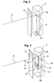
- the target 12 mounted directly on the inside of the bottom of the housing 2.
- the function of the target 12 can be replaced by a simple contrast mark in the case back. If the housing 2 is produced, for example, by die-casting or plastic injection molding, this contrast mark can even be taken into account even in the tool mold, with the result that practically no further costs arise for the actual target 12 of the target device.
- Fig. 3 Another embodiment of the aiming device is in Fig. 3 shown.
- the function of the deflection mirror 10 and the target 12 is performed by an optical prism 14.
- the directional beam 9 passes through the base surface 15 which is parallel is aligned with the lens 11, in the prism 14 a. Since the directional beam 9 impinges perpendicularly on the base surface 15, the directional beam 9 is also not deflected and meets the inclined at an angle of 45 ° to the base surface first outer surface 16. Since the prism of an optical material having a refractive index n of about 1 5, the directional beam 9 is deflected by 90 ° by means of total reflection.
- This deflected directional beam 9 hits in the sequence on the second outer surface 17 which forms an angle of 90 ° with the first outer surface.
- the directional beam 9 ' is again deflected by 90 ° in a new total reflection so that the directional beam 9 "is deflected by 180 ° relative to the original directional beam 9 and struck by the amount A again impinges on the base surface 15.
- the base surface 15 of the prism 14 is not polished in this area 18, but has a matte surface, comparable to a ground glass screen.
- the spread of the beam 9 "caused by the ground glass disc is made very clear the impact point.
- This matt area 18 thus assumes the function of the target 12. Again, it is provided to mark the target point in the frosted area, for example, with an annular and / or with cross-shaped lines 13.
- this variant represents a very effective and inexpensive solution.
Landscapes
- Engineering & Computer Science (AREA)
- General Engineering & Computer Science (AREA)
- General Physics & Mathematics (AREA)
- Physics & Mathematics (AREA)
- Life Sciences & Earth Sciences (AREA)
- General Life Sciences & Earth Sciences (AREA)
- Mechanical Engineering (AREA)
- Geophysics (AREA)
- Optical Radar Systems And Details Thereof (AREA)
- Optical Elements Other Than Lenses (AREA)
- Eye Examination Apparatus (AREA)
- Liquid Crystal (AREA)
- Optical Communication System (AREA)
Description
- Die Erfindung betrifft eine Lichtschranke oder ein Lichtgitter nach dem Oberbegriff des Anspruchs 1.
- Derartige Lichtschranken oder Lichtgitter werden verwendet, um Zugangsbereiche zum Beispiel an gefahrbringenden Werkzeugmaschinen zu überwachen.
- Während in einer Lichtschranke nur ein Lichtsender und nur ein Lichtempfänger eingebaut sind, die den Zugangsbereich mit einer Linie durchstrahlen, sind bei einem Lichtgitter mehrere Lichtsender und Lichtempfänger vorhanden, die diesen gefährdeten Bereich an mehreren parallel zueinander versetzten Linien durchstrahlen.
- Der Begriff "Licht" ist hierbei auf das sichtbare Licht beschränkt.
- In den hier beschriebenen Lichtschranken bzw. Lichtgittern nach dem Einwegprinzip sind der bzw. die Lichtsender in einem ersten Gehäuse und der bzw. die Lichtempfänger in einem zweiten Gehäuse eingebaut. Damit die Lichtsender auf der einen Seite des zu überwachenden Zugangsbereiches mit den Lichtempfängern auf der anderen Seite des Zugangsbereiches miteinander korrespondieren können ist es notwendig, die beiden Gehäuse gegenseitig aufeinander auszurichten, d. h. sie müssen ggf. linear verschoben, gedreht oder gekippt werden. Aus diesem Grunde ist es bekannt, zum Ausrichten dieser Gehäuse sogenannte Ausrichthilfen zu verwenden. So kann besonders bei großen Abständen vom Lichtsender zum Lichtempfänger die Ausrichtung der Gehäuse mit einem fest eingebauten oder externen adaptierbaren Zielfernrohr durchgeführt werden. Weiterhin ist bekannt, die Justage unter Zuhilfenahme des eigenen Lichtschranken-/Lichtgittersignals vorzunehmen. Bei dieser Methode wird die Ausrichtung des Lichtsenders und des Lichtempfängers so lange verändert, bis das Empfangssignal einen maximalen Wert erreicht hat. Dazu ist es bekannt, zum Beispiel in Abhängigkeit von der Größe des Empfangssignals, die Blinkfrequenz einer Anzeigediode zu verändern oder beispielsweise ein akustisches Signal auszugeben.
Eine weitere Einrichtung zum Ausrichten der beiden Gehäuse ist aus derEP 0 889 332 B1 bekannt. In dieser Druckschrift wird ein Verfahren und eine Vorrichtung beschrieben, bei der in jedem Gehäuse ein Ausrichtlichtsender zum Aussenden eines Richtstrahles vorhanden ist, bzw. der zweite Richtstrahl vom ersten Richtstrahl durch mehrere exakt justierte Umlenkspiegel erzeugt wird. - Nachteilig bei dem bekannten Verfahren zur Ausrichtung der Lichtschranke/Lichtgitter sind zum Beispiel bei der Zielfernrohrlösung die damit verbundenen Kosten und der benötigte Platzbedarf. Bei der Lösung unter Zuhilfenahme des Empfangssignals ist dagegen der zum Ausrichten erforderliche Zeitaufwand recht hoch.
Der Nachteil bei der in der DruckschriftEP 0 889 332 B1 beschriebenen Ausrichthilfe besteht darin, dass es bei der gegenseitigen geometrischen Ausrichtung der beiden Gehäuse notwendig ist, dass immer das gegenüberliegende Gehäuse eingesehen werden muss, um die Ausrichtung durchführen zu können. Dies kann insbesondere bei großen Abständen und hoher Umgebungshelligkeit zu Problemen führen. Besonders schwierig ist diese Art der Ausrichthilfe dann, wenn die Lichtstrahlen der Lichtschranke/Lichtgitter mit Umlenkspiegeln durch einen abgewinkelten Zugangsbereich geführt werden. Außerdem ist diese Ausrichthilfe durch die Tatsache, dass in jedem Gehäuse ein Ausrichtlichtsender eingebaut und betrieben werden muss, bzw. dadurch, dass mehrere genau justierte Umlenkspiegel notwendig sind, insgesamt kostenaufwendig. Zudem wird viel Zeit für die Ausrichtung benötigt. - Weitere Ausrichthilfen sind aus den Druckschriften
DE 203 17 622 U1 undUS 3,752,978 bekannt. - Der Erfindung liegt die Aufgabe zugrunde, eine Lichtschranke oder ein Lichtgitter der eingangs genannten Art derart mit einer Ausrichthilfe auszubilden, dass dafür nur geringe Herstellkosten entstehen, dass die Baugröße der Lichtschranken/Lichtgitter durch die Ausrichthilfe nicht vergrößert wird und dass der Einsatz selbst bei großen Abständen der beiden Gehäuse und/oder beim Einsatz von Umlenkspiegel im Zugangsbereich problemlos möglich ist.
- Erfindungsgemäß besteht die Lösung in einer Lichtschranke oder einen Lichtgitter gemäß Anspruch 1 oder Anspruch 6.
- Der Vorteil diesen erfindungsgemäßen Ausbildungen des zweiten Gehäuses mit einer Zieleinrichtung zur Ausrichtung auf den bzw. die vom gegenüberliegenden Gehäuse ausgesandten Richtstrahlen, ermöglicht die optischen Achsen der in diesem Gehäuse eingebauten Lichtsender/Lichtempfänger exakt auf das erste Gehäuse auszurichten. Da mit der Zieleinrichtung der Ausrichtungszustand des zweiten Gehäuses auf den, bzw. die Richtstrahlen direkt im zweiten Gehäuse angezeigt wird, ist es auch nicht notwendig, dass zur Ausrichtung dieses zweiten Gehäuses das erste Gehäuse eingesehen werden muss. Da die integrierte Zieleinrichtung lediglich aus einer den Richtstrahl ablenkenden Fläche besteht, ist der dafür benötigte Platzbedarf klein, die damit verbundenen Herstellkosten sehr gering.
- Eine vorteilhafte Weiterbildung der Erfindung sieht vor, dass die Zielscheibe unter einem Winkel von ca. 45° zu der Lichteintrittsfläche des Gehäuses angeordnet ist.
- Dadurch ist es dem Einrichter möglich, die Zielscheibe innerhalb des Gehäuses unter einem großen Blickwinkel einsehen zu können.
- Eine unter Kostengesichtspunkten optimierte Variante sieht vor, dass die Zielscheibe auf der Innenseite des Bodens vom Gehäuse angeordnet ist. Dadurch ist es möglich, die Funktion der Zielscheibe durch einfache Kontrastmarken, die auf der Innenseite des Bodens angebracht sind, zu ersetzen. Insbesondere dann, wenn das Gehäuse beispielsweise in Druckguss- oder Kunstzoffspritztechnik hergestellt wird, können diese Kontrastmarken bereits in der Werkzeugform angebracht sein, so dass keine weiteren Kosten für die Zielscheibe entstehen und der Aufwand für deren Einbau einer separaten Zielscheibe im Gehäuse entfällt.
- In einer vorteilhaften Ausbildung der Zielscheibe ist es vorgesehen, dass auf der Zielscheibe um den Sollpunkt herum ringförmige und/oder kreuzförmige Linien angeordnet sind. Dadurch wird der Ausrichtvorgang erleichtert, denn der Sollpunkt, auf den der Richtstrahl hingeführt werden muss, ist gut zu erkennen.
- Wenn sich die Zieleinrichtung im Wesentlichen entlang der Gehäuseachse erstreckt, die senkrecht zum auftreffenden Richtstrahl verläuft, hat dies insbesondere bei der Anwendung der Erfindung in einem Lichtgitter den großen Vorteil, dass die beim Lichtgitter systembedingte Baulänge des Gehäuses dazu genutzt werden kann, den optischen Weg des Richtstrahles zwischen dem Umlenkspiegel und der Zielscheibe groß zu halten und damit den Richtstrahl in Form eines langen optischen Zeigers zu nutzen, was die Anzeigegenauigkeit der Zieleinrichtung wesentlich erhöht.
- Die Erfindung sieht ebenso vor, dass eine optisch eblerhende Fläche und eine Zielfläche der Zieleinrichtung, in einem optisch transparenten Prisma zusammengefasst sind. Dieses Prisma, das hinsichtlich seiner optisch wirksamen Flächen die Form eines Halbwürfels aufweist, hat den großen Vorteil, dass die Justage des Umlenkspiegels und der Zielscheibe zueinander entfällt, weil dies durch die Bauform des Prismas vorgegeben wird. Ebenso ist auch die Justage dieser nur aus einem Prisma bestehenden Zieleinrichtung innerhalb des Gehäuses sehr einfach, weil nur die Basisfläche des Prismas parallel zu der Gehäusefläche ausgerichtet werden muss, in die der ankommende Richtstrahl eintritt.
- Es ist aus mehreren Gründen von besonderem Vorteil, wenn die Zieleinrichtung innenliegend im Gerät angeordnet ist. In diesem Fall ist es jedoch notwendig, dass der Richtstrahl in das Gehäuse eindringen kann und dass auch die Zielscheibe von Außen einsehbar ist. Aus diesem Grunde ist es notwendig, dass im Gehäuse entsprechende Fenster vorhanden sind. Da die Lichtschranken-/Lichtgittergehäuse oft unter rauen Umweltbedingungen betrieben werden, d. h. in der Regel eine hohe Schutzklasse aufweisen müssen, ist es notwendig, dass beim Einbau aller optischen Fenster im Gehäuse hohe Dichtigkeitsanforderungen erfüllt werden. Jedes zusätzliche Fenster verursacht deshalb nicht unerhebliche zusätzliche Kosten. In Weiterbildung der Erfindung wird deshalb vorgeschlagen, zum Eintritt des Richtstrahles ins Gehäuse und zur Beobachtung des Auftreffpunktes des Richtstrahles auf der Zielscheibe die für den Funktionsbetrieb der Lichtschranken-/Lichtgitter vorhandene Abschlussscheibe ggf. so anzupassen, dass für alle Funktionen nur eine gemeinsame Abschlussscheibe im Gehäuse eingebaut werden muss. Dies hat den Vorteil, dass sich somit durch den Einbau der Zieleinrichtung die Herstellkosten des Gehäuses nicht oder nur unwesentlich erhöhen.
- Schließlich ist in einer weiteren Ausbildung der Erfindung vorgesehen, dass die Zielscheibe die Form eines zweidimensionalen ortsauflösenden Empfangselementes hat, so dass neben der visuellen Betrachtung des Auftreffpunktes des reflektierten Richtstrahls, dieser auch, zum Beispiel in Form einer numerischen Anzeige, darstellbar ist. Auf diese Art kann die mit der Zieleinrichtung erreichbare Justiergenauigkeit ggf. deutlich erhöht werden.
- Im Folgenden wird die Erfindung an Hand von Ausführungsbeispielen unter Bezugnahme auf die Zeichnungen im Einzelnen erläutert.
In der Zeichnung zeigen: - Figur 1
- eine perspektivische Darstellung einer Lichtschrankenanordnung mit einem einen Richtstrahl aussendenden ersten Gehäuse und einem zweiten Gehäuse mit Zieleinrichtung;
- Figur 2
- eine perspektivische Darstellung einer Zieleinrichtung mit Umlenkspiegel und Zielscheibe, die auf dem Boden des Gehäuses angeordnet ist;
- Figur 3
- eine perspektivische Darstellung einer Zieleinrichtung, bei welcher die optisch ablenkende Fläche und die Zielfläche in einem gemeinsamen Prisma zusammengefasst sind.
- Die
Figur 1 zeigt eine Lichtschrankenanordnung mit einem ersten Gehäuse 1 und einem zweiten Gehäuse 2. In dem ersten Gehäuse 1 ist beispielsweise ein Lichtsender, bestehend aus einer Lichtquelle 3 und einer Sendeoptik 4 eingebaut, welcher mit einem Lichtempfänger, bestehend aus einem lichtempfindlichen Element 5 und einer Empfangsoptik 6 im zweiten Gehäuse 2 korrespondiert. Die optische Achse des Lichtsenders 7 als auch die optische Achse des Lichtempfängers 8 sind dabei exakt innerhalb dem jeweiligen Gehäuse justiert. - Zwischen dem ersten Gehäuse 1 und dem zweiten Gehäuse 2 befindet sich der zu überwachende Zugangsbereich S. Damit der Lichtsender mit dem Lichtempfänger korrespondieren kann, müssen beide Gehäuse aufeinander ausgerichtet werden. Dazu ist es notwendig, die beiden Gehäuse jeweils zumindest in den beiden Rotationsachsen x und y so zu verschwenken, dass der vom Lichtsender ausgesandte Lichtstrahl vom Lichtempfänger optimal erfasst wird. Über entsprechende Montagemittel werden die beiden ausgerichteten Gehäuse in dieser Lage am jeweiligen Einbauort fixiert.
Um die gegenseitige Justage der beiden Gehäuse durchführen zu können ist es vorgesehen, dass aus dem ersten Gehäuse 1 ein gut sichtbarer Richtstrahl 9, beispielsweise ein paralleler roter Laserstrahl, ausgesandt wird. Dieser Richtstrahl 9 wurde zuvor bei der werksseitigen Montage so im Gehäuses 1 ausgerichtet, dass er exakt in der gleichen Richtung wie der Lichtsender der Lichtschranke aus dem Gehäuse 1 austritt. Wird nun das Gehäuses 1 um eine oder beide Rotationsachsen x bzw. y verschwenkt, so verändert sich dann natürlich die Abstrahlrichtung des Richtstrahls 9 und die optische Achse 7 des Lichtsenders in gleichem Maße. Dies wiederum bedeutet, dass wenn der Richtstrahl 9 exakt auf das Zentrum eines im zweiten Gehäuse eingebauten Umlenkspiegels 10 fällt, das Gehäuse 1 und damit auch der Lichtsender richtig zum Gehäuse 2 justiert ist.
Im nachfolgenden Justageschritt muss nun das Gehäuse 2 in seinen Rotationsachsen x und y derart justiert werden, dass die optische Achse 8 des Lichtempfängers genau auf den einfallenden Lichtstrahl der Lichtschranke ausgerichtet ist. Zu diesem Zweck ist im Gehäuse 2 hinter einer Abschlussscheibe 11 eine Zieleinrichtung, bestehend aus dem Umlenkspiegel 10 und einer Zielscheibe 12, vorgesehen. Gemäß der Darstellung inFigur 1 ist der Umlenkspiegel 10 hinter der Abschlussscheibe 11 unter einem Winkel von 45° angeordnet. Der auftreffende Richtstrahl 9 wird an diesem Umlenkspiegel 10, entsprechend dem optischen Reflexionsgesetz, umgelenkt und als Richtstrahl 9' im Gehäuse 2 zur Zielscheibe 12 geleitet. Im Ausführungsbeispiel, gemässFigur 1 , ist die Zielscheibe 12 unter einem Winkel von näherungsweise 45° angeordnet. Die Oberfläche der Zielscheibe 12 ist so ausgebildet, dass der auftreffende Richtstrahl 9' daran diffus gestreut wird. Auf diese Weise kann genau erkannt werden, an welchem Ort der Richtstrahl 9' auf die Zielscheibe 12 auftrifft. Wie bereits erwähnt, ist der Umlenkspiegel 10 unter einem Winkel von 45° hinter der Abschlussscheibe 11 angeordnet. Dies bedeutet, dass der auftreffende Richtstrahl 9 nur dann exakt um 90° am Umlenkspiegel 10 abgelenkt wird, wenn der Richtstrahl 9 exakt rechtwinklig auf die Abschlussscheibe 11 auftrifft. Da die Zielscheibe 12 innerhalb der Zieleinrichtung in einer genauen geometrischen Zuordnung platziert ist, wird der am Umlenkspiegel 10 reflektierte Richtstrahl 9' auch nur dann genau das Zentrum der Zielscheibe 12 treffen, wenn der Richtstrahl 9 exakt rechtwinklig auf die Abschlussscheibe 11 auftrifft. Die Abschlussscheibe 11, welche inFigur 1 zum Zwecke der besseren Darstellung mit geringen Abstand vom Gehäuse 2 entfernt dargestellt ist, schließt in der Realität direkt das Gehäuse 2 auf der Seite des Lichteintritts ab. Gleichzeitig ist die Abschlussscheibe 11 von ihrer Größe so dimensioniert, dass sowohl der Lichtstrahl der Lichtschranke als auch der Richtstrahl 9 ungehindert in das Gehäuse 2 eindringen können und dass der Einrichter bei der Ausrichtung und Montage der Lichtschranke einen ungehinderten Einblick auf die Zielscheibe 12 nehmen kann. Auf der Zielscheibe 12 ist das Zentrum, d. h. der Sollpunkt, auf den der reflektierte Richtstrahl 9' eingerichtet werden soll, beispielsweise mit einer ringförmigen und/oder mit kreuzförmig angeordneten Linien 13 gekennzeichnet. - In einem weiteren Ausführungsbeispiel der Zieleinrichtung ist, wie in
Figur 2 dargestellt, die Zielscheibe 12 direkt auf der Innenseite des Bodens vom Gehäuse 2 angebracht. Dies führt zu einer sehr kostengünstigen Ausführungsvariante, weil in diesem Falle die Funktion der Zielscheibe 12 durch eine einfache Kontrastmarke im Gehäuseboden ersetzt werden kann. Wenn das Gehäuse 2 beispielsweise in Druckguss- oder Kunststoffspritztechnik hergestellt wird, kann diese Kontrastmarke sogar schon in der Werkzeugform berücksichtig werden mit der Folge, dass dann für die eigentliche Zielscheibe 12 der Zieleinrichtung praktisch keine weiteren Kosten mehr entstehen. - Eine andere Ausführungsform der Zieleinrichtung ist in der
Fig. 3 gezeigt. Hier wird die Funktion des Umlenkspiegels 10 und der Zielscheibe 12 von einem optischen Prisma 14 ausgeführt. Der Richtstrahl 9 tritt dabei durch die Basisfläche 15, die parallel zu Abschlussscheibe 11 ausgerichtet ist, in das Prisma 14 ein. Da der Richtstrahl 9 senkrecht auf die Basisfläche 15 auftrifft, wird der Richtstrahl 9 auch nicht abgelenkt und trifft auf die unter einem Winkel von 45° zur Basisfläche geneigte erste Außenfläche 16. Da das Prisma aus einem optischen Material mit einer Brechzahl n von ca. 1,5 hergestellt ist, wird der Richtstrahl 9 mittels einer Totalreflexion um 90° umgelenkt. Dieser umgelenkte Richtstrahl 9' trifft in der Folge auf die zweite Außenfläche 17, die mit der ersten Außenfläche einen Winkel von 90° bildet. An dieser zweiten Außenfläche 17 wird der Richtstrahl 9' in einer erneuten Totalreflexion wiederum um 90° umgelenkt, so dass der Richtstrahl 9" gegenüber dem ursprünglichen Richtstrahl 9 um 180° umgelenkt und um den Betrag A versetzt wieder auf die Basisfläche 15 auftrifft. Die Basisfläche 15 vom Prisma 14 ist in diesem Bereich 18 nicht poliert, sondern hat eine matte Oberfläche, vergleichbar mit einer Mattscheibe. Durch die von der Mattscheibe verursachte Aufstreuung des Richtstrahls 9" wird der Auftreffpunkt sehr gut deutlich gemacht. Dieser matte Bereich 18 übernimmt somit die Funktion der Zielscheibe 12. Auch hier ist es vorgesehen, in dem mattierten Bereich den Sollpunkt beispielsweise mit einer ringförmigen und/oder mit kreuzförmig angeordneten Linien 13 zu kennzeichnen. Insbesondere dann, wenn das Prisma 14 als Kunststoffprisma ausgeführt ist, stellt diese Variante eine sehr wirkungsvolle und preiswerte Lösung dar.
Claims (10)
- Lichtschranke oder Lichtgitter mit wenigstens einem in einem ersten Gehäuse (1) angeordneten Lichtsender und mit wenigstens einem in einem zweiten Gehäuse (2) angeordneten und mit dem Lichtsender korrespondierenden Lichtempfänger sowie mit wenigstens einem im ersten oder zweiten Gehäuse eingebauten Ausrichtlichtsender zur Erzeugung wenigstens eines sichtbaren Richtstrahles (9) zur geometrischen Ausrichtung des Lichtsender auf den gegenüberliegenden Lichtempfänger, und in dem von dem Richtstrahl (9) beaufschlagten Gehäuse (2)mindestens eine Zieheinrichtung vorhanden ist, dadurch gekennzeichnet, dass die Zieleinrichtung aus mindestens einer den Richtstrahl (9) optisch ablenkenden Fläche (10) und einer Zielscheibe (12) besteht und die optisch ablenkende Fläche (10) den Richtstrahl (9) um 90° auf die Zielscheibe (12) ablenkt, so dass sich die Zieleinrichtung entlang der Gehäuseachse erstreckt, die senkrecht zum auftreffenden Richtstrahl (9) verläuft und die Oberfläche der Zielscheibe (12) derart ausgebildet ist, dass der auftreffende Lichtstrahl daran diffus gestreut wird
- Lichtschranke oder Lichtgitter nach Anspruch 1, dadurch gekennzeichnet, dass die Zielscheibe (12) unter einem Winkel von 45° zu der Lichteintrittsfläche des Gehäuses (2) angeordnet ist.
- Lichtschranke oder Lichtgitter nach Anspruch 1, dadurch gekennzeichnet, dass die Zielscheibe (12) auf der Innenseite des Bodens des Gehäuses (2) angeordnet ist.
- Lichtschranke oder Lichtgitter nach einem der vorhergehenden Ansprüche, dadurch gekennzeichnet, dass auf der Zielscheibe (12) um den Sollpunkt herum ringförmige und/oder kreuzförmige Linien (13) angeordnet sind.
- Lichtschranke oder Lichtgitter nach einem der vorhergehenden Ansprüche, dadurch gekennzeichnet, dass zum Eintritt des Richtstrahles (9) ins Gehäuse, zur Beobachtung des Auftreffpunktes des Richtstrahles (9) auf der Zelscheibe (12) und zum Lichtschranken-/Lichtgitterbetrieb die gleiche Abschlussscheibe (11) benutzt werden kann.
- Lichtschranke oder Lichtgitter mit wenigstens einem in einem ersten Gehäuse (1) angeordneten Lichtsender und mit wenigstens einem in einem zweiten Gehäuse (2) angeordneten und mit dem Lichtsender korrespondierenden Lichtempfänger sowie mit wenigstens einem im ersten oder zweiten Gehäuse eingebauten Ausrichtlichtsender zur Erzeugung wenigstens eines sichtbaren Richtstrahles (9) zur geometrischen Ausrichtung des Lichtsenders auf den gegenüberliegenden Lichtempfänger, und in dem von dem Richtstrahl (9) beaufschlagten Gehäuse (2) mindestens eine Zieleinrichtung vorhanden ist, dadurch gekennzeichnet, dass die Zieleinrichtung aus mindestens einer den Richtstrahl (9) optisch ablenkenden Fläche (10) und einer Zielfläche (15) besteht, wobei die optisch ablenkenden Fläche (10) und die Zielfläche (15) der Zieleinrichtung in einem optisch transparenten Prisma (14) zusammengefasst sind.
- Lichtschranke oder Lichtgitter nach Anspruch 6, dadurch gekennzeichnet, dass die Zielfläche (15) unter einem Winkel von 45° zu der Lichteintrittsfläche des Gehäuses (2) angeordnet ist.
- Lichtschranke oder Lichtgitter nach einem der Ansprüche 6-7, dadurch gekennzeichnet, dass auf der Zielfläche (15) um den Sollpunkt herum ringförmige und/oder kreuzförmige Linien (13) angeordnet sind.
- Lichtschranke oder Lichtgitter nach einem der vorhergehenden Ansprüche, dadurch gekennzeichnet, dass sich die Zieleinrichtung im Wesentlichen entlang der Gehäuseachse erstreckt, die senkrecht zum auftreffenden Richtstrahl (9) verläuft.
- Lichtschranke oder Lichtgitter nach einem der Ansprüche 6-9, dadurch gekennzeichnet, dass zum Eintritt des Richtstrahles (9) ins Gehäuse, zur Beobachtung des Auftreffpunktes des Richtstrahles (9) auf der Zielfläche (15) und zum Lichtschranken-/Lichtgitterbetrieb die gleiche Abschlussscheibe (11) benutzt werden kann.
Applications Claiming Priority (2)
| Application Number | Priority Date | Filing Date | Title |
|---|---|---|---|
| DE102004008059A DE102004008059A1 (de) | 2004-02-19 | 2004-02-19 | Lichtschranke oder Lichtgitter mit Ausrichthilfe |
| DE102004008059 | 2004-02-19 |
Publications (2)
| Publication Number | Publication Date |
|---|---|
| EP1566588A1 EP1566588A1 (de) | 2005-08-24 |
| EP1566588B1 true EP1566588B1 (de) | 2008-09-17 |
Family
ID=34706851
Family Applications (1)
| Application Number | Title | Priority Date | Filing Date |
|---|---|---|---|
| EP05000681A Expired - Lifetime EP1566588B1 (de) | 2004-02-19 | 2005-01-14 | Lichtschranke oder Lichtgitter mit Ausrichthilfe |
Country Status (4)
| Country | Link |
|---|---|
| US (1) | US7087884B2 (de) |
| EP (1) | EP1566588B1 (de) |
| AT (1) | ATE408783T1 (de) |
| DE (2) | DE102004008059A1 (de) |
Cited By (1)
| Publication number | Priority date | Publication date | Assignee | Title |
|---|---|---|---|---|
| DE202014101316U1 (de) | 2014-03-21 | 2015-08-07 | Sick Ag | Vorrichtung zur Justage eines Laserstrahls |
Families Citing this family (13)
| Publication number | Priority date | Publication date | Assignee | Title |
|---|---|---|---|---|
| FR2898716B1 (fr) * | 2006-03-16 | 2008-12-26 | Rhodanienne D Electronique App | Barriere a infrarouge actif a cellules mixtes a la fois emettrices et receptrices |
| EP1876474A2 (de) * | 2006-07-04 | 2008-01-09 | Marantec Antriebs- und Steuerungstechnik GmbH & Co. KG. | Justierbares Lichtschrankenelement |
| DE202006010483U1 (de) * | 2006-07-06 | 2007-11-08 | Marantec Antriebs- Und Steuerungstechnik Gmbh & Co. Kg | Justierbarer Lichtschrankensender |
| DE102006053359C5 (de) * | 2006-11-10 | 2015-12-10 | Sick Ag | Optoelektronische Sensoranordnung und Verfahren zum Justieren einer optoelektronischen Sensoranordnung |
| DE102006059547B4 (de) * | 2006-12-16 | 2009-05-07 | Leuze Lumiflex Gmbh + Co. Kg | Lichtschrankenanordnung |
| US7645980B2 (en) * | 2007-01-19 | 2010-01-12 | The Boeing Company | Photoelectric switch having a prism with a reflective surface being positioned by a release button |
| DE102007009244A1 (de) * | 2007-02-22 | 2008-08-28 | Sick Ag | Verfahren zur Überprüfung der Funktionsweise und/oder Justierung einer optoelektronischen Sensoranordnung und optoelektronische Sensoranordnung |
| ATE511112T1 (de) * | 2008-08-21 | 2011-06-15 | Sick Ag | Lichtgitter |
| DE202009000776U1 (de) | 2009-01-21 | 2009-06-25 | Sick Ag | Sicherheits-Lichtgitter |
| DE102010043359A1 (de) * | 2010-11-04 | 2012-05-10 | Robert Bosch Gmbh | Lichtstrahlempfänger mit Sprachausgabe |
| EP2624017B1 (de) * | 2012-02-02 | 2020-06-17 | Rockwell Automation Switzerland GmbH | Integrierte Laserausrichtungshilfe unter Verwendung mehrerer Laserpunkte aus einem einzigen Laser |
| EP3783394B1 (de) * | 2019-08-22 | 2021-10-06 | Sick Ag | Lichtgitter und verfahren zum erfassen von objekten |
| US20210180386A1 (en) * | 2019-12-13 | 2021-06-17 | Qianliang QIU | Wireless safety system for Gate Opening Apparatus |
Family Cites Families (6)
| Publication number | Priority date | Publication date | Assignee | Title |
|---|---|---|---|---|
| US3752978A (en) * | 1971-02-04 | 1973-08-14 | Arrowhead Ets Inc | Photoelectric intrusion detector |
| GB9309750D0 (en) * | 1993-05-12 | 1993-07-21 | Pilkington Perkin Elmer Ltd | Method of monitoring coalignment of a sighting or surveilance sensor suite |
| PT889332E (pt) * | 1997-06-30 | 2002-04-29 | Cedes Ag | Barreira fotoelectrica ou cortina de luzcom auxiliar para alinhamento |
| US6614579B2 (en) * | 1999-10-22 | 2003-09-02 | Gentex Corporation | Proximity switch and vehicle rearview mirror assembly incorporating the same and having a transparent housing |
| US6635895B2 (en) * | 2000-09-07 | 2003-10-21 | Fife Corporation | Edge scan sensor for web guiding apparatus |
| DE20317622U1 (de) * | 2003-11-14 | 2004-02-12 | Sick Ag | Lichtschranke |
-
2004
- 2004-02-19 DE DE102004008059A patent/DE102004008059A1/de not_active Withdrawn
-
2005
- 2005-01-14 DE DE502005005369T patent/DE502005005369D1/de not_active Expired - Lifetime
- 2005-01-14 EP EP05000681A patent/EP1566588B1/de not_active Expired - Lifetime
- 2005-01-14 AT AT05000681T patent/ATE408783T1/de not_active IP Right Cessation
- 2005-02-16 US US11/060,245 patent/US7087884B2/en not_active Expired - Fee Related
Cited By (1)
| Publication number | Priority date | Publication date | Assignee | Title |
|---|---|---|---|---|
| DE202014101316U1 (de) | 2014-03-21 | 2015-08-07 | Sick Ag | Vorrichtung zur Justage eines Laserstrahls |
Also Published As
| Publication number | Publication date |
|---|---|
| US7087884B2 (en) | 2006-08-08 |
| ATE408783T1 (de) | 2008-10-15 |
| EP1566588A1 (de) | 2005-08-24 |
| DE102004008059A1 (de) | 2005-09-22 |
| US20050184225A1 (en) | 2005-08-25 |
| DE502005005369D1 (de) | 2008-10-30 |
Similar Documents
| Publication | Publication Date | Title |
|---|---|---|
| EP1566588B1 (de) | Lichtschranke oder Lichtgitter mit Ausrichthilfe | |
| EP1394504B1 (de) | Lichtgitter | |
| EP2378309A1 (de) | Optoelektronischer Sensor und Verfahren zur Erzeugung von Informationen über Objekte in einem Überwachungsbereich | |
| DE102017107667A1 (de) | Laserscanner und Verfahren zur Überprüfung der Funktionsfähigkeit | |
| EP1246148A2 (de) | Vorrichtung zur Überwachung eines Schutzfeldes | |
| EP2159599B1 (de) | Optoelektronischer Sensor | |
| DE102006050189B4 (de) | Lichtgitter mit Ausrichtlichtsender und Verfahren zum Ausrichten | |
| EP3150968A1 (de) | Optoelektronischer sensor | |
| EP1600684B1 (de) | Justiervorrichtung insbesondere für Lichtschranken oder Lichtgitter und Verfahren zur Justage | |
| DE102018212823A1 (de) | LIDAR-Vorrichtung zur Erfassung eines Objektes | |
| EP3367050A1 (de) | Messrahmen mit optischem filter zur berührungslosen optischen ermittlung einer durchschussposition | |
| EP1531345B1 (de) | Justierhilfe für Lichtschranken | |
| DE102006053359C5 (de) | Optoelektronische Sensoranordnung und Verfahren zum Justieren einer optoelektronischen Sensoranordnung | |
| EP1574880B1 (de) | Sendeelement für Lichtschranken, Lichtgitter und dergleichen | |
| DE10314852A1 (de) | Optoelektronische Zugangsabsicherung | |
| DE2811413A1 (de) | Naeherungsschalter | |
| DE102020204536A1 (de) | Laservorrichtung und Verfahren zum Einstellen einer Laservorrichtung | |
| EP1589355B1 (de) | Verfahren zur Justage einer Sicherheitseinrichtung und optoelektronische Sicherheitseinrichtung | |
| DE102012100746B4 (de) | Sendeeinheit für einen optischen Sensor | |
| DE102007055497B4 (de) | Optischer Sensor für ein Kraftfahrzeug | |
| DE202008009090U1 (de) | Optoelektronischer Sensor | |
| EP2746820B1 (de) | Optischer Sensor | |
| DE102008028970B4 (de) | Verfahren zur Ausrichtung eines optischen Sensors | |
| EP2270438B1 (de) | Durchflusszähler | |
| EP3667270B1 (de) | Lichtregelung durch leuchtenabdeckung |
Legal Events
| Date | Code | Title | Description |
|---|---|---|---|
| PUAI | Public reference made under article 153(3) epc to a published international application that has entered the european phase |
Free format text: ORIGINAL CODE: 0009012 |
|
| AK | Designated contracting states |
Kind code of ref document: A1 Designated state(s): AT BE BG CH CY CZ DE DK EE ES FI FR GB GR HU IE IS IT LI LT LU MC NL PL PT RO SE SI SK TR |
|
| AX | Request for extension of the european patent |
Extension state: AL BA HR LV MK YU |
|
| 17P | Request for examination filed |
Effective date: 20051025 |
|
| AKX | Designation fees paid |
Designated state(s): AT BE BG CH CY CZ DE DK EE ES FI FR GB GR HU IE IS IT LI LT LU MC NL PL PT RO SE SI SK TR |
|
| RAP1 | Party data changed (applicant data changed or rights of an application transferred) |
Owner name: SICK AG |
|
| GRAP | Despatch of communication of intention to grant a patent |
Free format text: ORIGINAL CODE: EPIDOSNIGR1 |
|
| GRAS | Grant fee paid |
Free format text: ORIGINAL CODE: EPIDOSNIGR3 |
|
| GRAA | (expected) grant |
Free format text: ORIGINAL CODE: 0009210 |
|
| AK | Designated contracting states |
Kind code of ref document: B1 Designated state(s): AT BE BG CH CY CZ DE DK EE ES FI FR GB GR HU IE IS IT LI LT LU MC NL PL PT RO SE SI SK TR |
|
| REG | Reference to a national code |
Ref country code: GB Ref legal event code: FG4D Free format text: NOT ENGLISH |
|
| REG | Reference to a national code |
Ref country code: CH Ref legal event code: EP |
|
| REG | Reference to a national code |
Ref country code: IE Ref legal event code: FG4D Free format text: LANGUAGE OF EP DOCUMENT: GERMAN |
|
| REF | Corresponds to: |
Ref document number: 502005005369 Country of ref document: DE Date of ref document: 20081030 Kind code of ref document: P |
|
| PG25 | Lapsed in a contracting state [announced via postgrant information from national office to epo] |
Ref country code: LT Free format text: LAPSE BECAUSE OF FAILURE TO SUBMIT A TRANSLATION OF THE DESCRIPTION OR TO PAY THE FEE WITHIN THE PRESCRIBED TIME-LIMIT Effective date: 20080917 |
|
| PG25 | Lapsed in a contracting state [announced via postgrant information from national office to epo] |
Ref country code: FI Free format text: LAPSE BECAUSE OF FAILURE TO SUBMIT A TRANSLATION OF THE DESCRIPTION OR TO PAY THE FEE WITHIN THE PRESCRIBED TIME-LIMIT Effective date: 20080917 Ref country code: SI Free format text: LAPSE BECAUSE OF FAILURE TO SUBMIT A TRANSLATION OF THE DESCRIPTION OR TO PAY THE FEE WITHIN THE PRESCRIBED TIME-LIMIT Effective date: 20080917 |
|
| NLV1 | Nl: lapsed or annulled due to failure to fulfill the requirements of art. 29p and 29m of the patents act | ||
| REG | Reference to a national code |
Ref country code: IE Ref legal event code: FD4D |
|
| PG25 | Lapsed in a contracting state [announced via postgrant information from national office to epo] |
Ref country code: BG Free format text: LAPSE BECAUSE OF FAILURE TO SUBMIT A TRANSLATION OF THE DESCRIPTION OR TO PAY THE FEE WITHIN THE PRESCRIBED TIME-LIMIT Effective date: 20081217 Ref country code: ES Free format text: LAPSE BECAUSE OF FAILURE TO SUBMIT A TRANSLATION OF THE DESCRIPTION OR TO PAY THE FEE WITHIN THE PRESCRIBED TIME-LIMIT Effective date: 20081228 |
|
| PG25 | Lapsed in a contracting state [announced via postgrant information from national office to epo] |
Ref country code: NL Free format text: LAPSE BECAUSE OF FAILURE TO SUBMIT A TRANSLATION OF THE DESCRIPTION OR TO PAY THE FEE WITHIN THE PRESCRIBED TIME-LIMIT Effective date: 20080917 Ref country code: SK Free format text: LAPSE BECAUSE OF FAILURE TO SUBMIT A TRANSLATION OF THE DESCRIPTION OR TO PAY THE FEE WITHIN THE PRESCRIBED TIME-LIMIT Effective date: 20080917 Ref country code: CZ Free format text: LAPSE BECAUSE OF FAILURE TO SUBMIT A TRANSLATION OF THE DESCRIPTION OR TO PAY THE FEE WITHIN THE PRESCRIBED TIME-LIMIT Effective date: 20080917 Ref country code: IS Free format text: LAPSE BECAUSE OF FAILURE TO SUBMIT A TRANSLATION OF THE DESCRIPTION OR TO PAY THE FEE WITHIN THE PRESCRIBED TIME-LIMIT Effective date: 20090117 Ref country code: RO Free format text: LAPSE BECAUSE OF FAILURE TO SUBMIT A TRANSLATION OF THE DESCRIPTION OR TO PAY THE FEE WITHIN THE PRESCRIBED TIME-LIMIT Effective date: 20080917 Ref country code: PT Free format text: LAPSE BECAUSE OF FAILURE TO SUBMIT A TRANSLATION OF THE DESCRIPTION OR TO PAY THE FEE WITHIN THE PRESCRIBED TIME-LIMIT Effective date: 20090217 |
|
| PLBE | No opposition filed within time limit |
Free format text: ORIGINAL CODE: 0009261 |
|
| STAA | Information on the status of an ep patent application or granted ep patent |
Free format text: STATUS: NO OPPOSITION FILED WITHIN TIME LIMIT |
|
| PG25 | Lapsed in a contracting state [announced via postgrant information from national office to epo] |
Ref country code: DK Free format text: LAPSE BECAUSE OF FAILURE TO SUBMIT A TRANSLATION OF THE DESCRIPTION OR TO PAY THE FEE WITHIN THE PRESCRIBED TIME-LIMIT Effective date: 20080917 Ref country code: IE Free format text: LAPSE BECAUSE OF FAILURE TO SUBMIT A TRANSLATION OF THE DESCRIPTION OR TO PAY THE FEE WITHIN THE PRESCRIBED TIME-LIMIT Effective date: 20080917 Ref country code: EE Free format text: LAPSE BECAUSE OF FAILURE TO SUBMIT A TRANSLATION OF THE DESCRIPTION OR TO PAY THE FEE WITHIN THE PRESCRIBED TIME-LIMIT Effective date: 20080917 |
|
| 26N | No opposition filed |
Effective date: 20090618 |
|
| PG25 | Lapsed in a contracting state [announced via postgrant information from national office to epo] |
Ref country code: MC Free format text: LAPSE BECAUSE OF NON-PAYMENT OF DUE FEES Effective date: 20090131 |
|
| GBPC | Gb: european patent ceased through non-payment of renewal fee |
Effective date: 20090114 |
|
| PG25 | Lapsed in a contracting state [announced via postgrant information from national office to epo] |
Ref country code: GB Free format text: LAPSE BECAUSE OF NON-PAYMENT OF DUE FEES Effective date: 20090114 |
|
| PG25 | Lapsed in a contracting state [announced via postgrant information from national office to epo] |
Ref country code: SE Free format text: LAPSE BECAUSE OF FAILURE TO SUBMIT A TRANSLATION OF THE DESCRIPTION OR TO PAY THE FEE WITHIN THE PRESCRIBED TIME-LIMIT Effective date: 20081217 |
|
| PG25 | Lapsed in a contracting state [announced via postgrant information from national office to epo] |
Ref country code: BE Free format text: LAPSE BECAUSE OF NON-PAYMENT OF DUE FEES Effective date: 20090131 |
|
| PG25 | Lapsed in a contracting state [announced via postgrant information from national office to epo] |
Ref country code: PL Free format text: LAPSE BECAUSE OF FAILURE TO SUBMIT A TRANSLATION OF THE DESCRIPTION OR TO PAY THE FEE WITHIN THE PRESCRIBED TIME-LIMIT Effective date: 20080917 |
|
| PG25 | Lapsed in a contracting state [announced via postgrant information from national office to epo] |
Ref country code: AT Free format text: LAPSE BECAUSE OF NON-PAYMENT OF DUE FEES Effective date: 20090114 |
|
| PG25 | Lapsed in a contracting state [announced via postgrant information from national office to epo] |
Ref country code: GR Free format text: LAPSE BECAUSE OF FAILURE TO SUBMIT A TRANSLATION OF THE DESCRIPTION OR TO PAY THE FEE WITHIN THE PRESCRIBED TIME-LIMIT Effective date: 20081218 |
|
| PG25 | Lapsed in a contracting state [announced via postgrant information from national office to epo] |
Ref country code: LU Free format text: LAPSE BECAUSE OF NON-PAYMENT OF DUE FEES Effective date: 20090114 |
|
| PG25 | Lapsed in a contracting state [announced via postgrant information from national office to epo] |
Ref country code: HU Free format text: LAPSE BECAUSE OF FAILURE TO SUBMIT A TRANSLATION OF THE DESCRIPTION OR TO PAY THE FEE WITHIN THE PRESCRIBED TIME-LIMIT Effective date: 20090318 |
|
| PG25 | Lapsed in a contracting state [announced via postgrant information from national office to epo] |
Ref country code: TR Free format text: LAPSE BECAUSE OF FAILURE TO SUBMIT A TRANSLATION OF THE DESCRIPTION OR TO PAY THE FEE WITHIN THE PRESCRIBED TIME-LIMIT Effective date: 20080917 |
|
| PG25 | Lapsed in a contracting state [announced via postgrant information from national office to epo] |
Ref country code: CY Free format text: LAPSE BECAUSE OF FAILURE TO SUBMIT A TRANSLATION OF THE DESCRIPTION OR TO PAY THE FEE WITHIN THE PRESCRIBED TIME-LIMIT Effective date: 20080917 |
|
| PGFP | Annual fee paid to national office [announced via postgrant information from national office to epo] |
Ref country code: FR Payment date: 20130207 Year of fee payment: 9 |
|
| PGFP | Annual fee paid to national office [announced via postgrant information from national office to epo] |
Ref country code: CH Payment date: 20140124 Year of fee payment: 10 |
|
| PGFP | Annual fee paid to national office [announced via postgrant information from national office to epo] |
Ref country code: IT Payment date: 20140129 Year of fee payment: 10 |
|
| REG | Reference to a national code |
Ref country code: FR Ref legal event code: ST Effective date: 20140930 |
|
| PG25 | Lapsed in a contracting state [announced via postgrant information from national office to epo] |
Ref country code: FR Free format text: LAPSE BECAUSE OF NON-PAYMENT OF DUE FEES Effective date: 20140131 |
|
| REG | Reference to a national code |
Ref country code: CH Ref legal event code: PL |
|
| PG25 | Lapsed in a contracting state [announced via postgrant information from national office to epo] |
Ref country code: CH Free format text: LAPSE BECAUSE OF NON-PAYMENT OF DUE FEES Effective date: 20150131 Ref country code: LI Free format text: LAPSE BECAUSE OF NON-PAYMENT OF DUE FEES Effective date: 20150131 |
|
| PG25 | Lapsed in a contracting state [announced via postgrant information from national office to epo] |
Ref country code: IT Free format text: LAPSE BECAUSE OF NON-PAYMENT OF DUE FEES Effective date: 20150114 |
|
| PGFP | Annual fee paid to national office [announced via postgrant information from national office to epo] |
Ref country code: DE Payment date: 20170125 Year of fee payment: 13 |
|
| REG | Reference to a national code |
Ref country code: DE Ref legal event code: R119 Ref document number: 502005005369 Country of ref document: DE |
|
| PG25 | Lapsed in a contracting state [announced via postgrant information from national office to epo] |
Ref country code: DE Free format text: LAPSE BECAUSE OF NON-PAYMENT OF DUE FEES Effective date: 20180801 |