EP1566549A2 - Compressor - Google Patents
Compressor Download PDFInfo
- Publication number
- EP1566549A2 EP1566549A2 EP05250925A EP05250925A EP1566549A2 EP 1566549 A2 EP1566549 A2 EP 1566549A2 EP 05250925 A EP05250925 A EP 05250925A EP 05250925 A EP05250925 A EP 05250925A EP 1566549 A2 EP1566549 A2 EP 1566549A2
- Authority
- EP
- European Patent Office
- Prior art keywords
- impeller
- compressor
- blade
- housing
- annular
- Prior art date
- Legal status (The legal status is an assumption and is not a legal conclusion. Google has not performed a legal analysis and makes no representation as to the accuracy of the status listed.)
- Granted
Links
- 239000000411 inducer Substances 0.000 claims abstract description 25
- 238000011144 upstream manufacturing Methods 0.000 claims description 12
- 238000010408 sweeping Methods 0.000 claims description 2
- 230000006872 improvement Effects 0.000 description 7
- 230000007423 decrease Effects 0.000 description 2
- 239000000446 fuel Substances 0.000 description 2
- 238000004519 manufacturing process Methods 0.000 description 2
- 230000002411 adverse Effects 0.000 description 1
- 230000000712 assembly Effects 0.000 description 1
- 238000000429 assembly Methods 0.000 description 1
- 230000033228 biological regulation Effects 0.000 description 1
- 230000008859 change Effects 0.000 description 1
- 238000002485 combustion reaction Methods 0.000 description 1
- 230000003247 decreasing effect Effects 0.000 description 1
- 238000000034 method Methods 0.000 description 1
- 238000012986 modification Methods 0.000 description 1
- 230000004048 modification Effects 0.000 description 1
- 230000009467 reduction Effects 0.000 description 1
Images


Classifications
-
- F—MECHANICAL ENGINEERING; LIGHTING; HEATING; WEAPONS; BLASTING
- F04—POSITIVE - DISPLACEMENT MACHINES FOR LIQUIDS; PUMPS FOR LIQUIDS OR ELASTIC FLUIDS
- F04D—NON-POSITIVE-DISPLACEMENT PUMPS
- F04D29/00—Details, component parts, or accessories
- F04D29/26—Rotors specially for elastic fluids
- F04D29/28—Rotors specially for elastic fluids for centrifugal or helico-centrifugal pumps for radial-flow or helico-centrifugal pumps
- F04D29/30—Vanes
-
- F—MECHANICAL ENGINEERING; LIGHTING; HEATING; WEAPONS; BLASTING
- F24—HEATING; RANGES; VENTILATING
- F24F—AIR-CONDITIONING; AIR-HUMIDIFICATION; VENTILATION; USE OF AIR CURRENTS FOR SCREENING
- F24F7/00—Ventilation
- F24F7/02—Roof ventilation
-
- F—MECHANICAL ENGINEERING; LIGHTING; HEATING; WEAPONS; BLASTING
- F04—POSITIVE - DISPLACEMENT MACHINES FOR LIQUIDS; PUMPS FOR LIQUIDS OR ELASTIC FLUIDS
- F04D—NON-POSITIVE-DISPLACEMENT PUMPS
- F04D29/00—Details, component parts, or accessories
- F04D29/26—Rotors specially for elastic fluids
- F04D29/28—Rotors specially for elastic fluids for centrifugal or helico-centrifugal pumps for radial-flow or helico-centrifugal pumps
- F04D29/284—Rotors specially for elastic fluids for centrifugal or helico-centrifugal pumps for radial-flow or helico-centrifugal pumps for compressors
Definitions
- the present invention relates to a compressor.
- the invention relates to a centrifugal compressor such as, for example, the compressor of a turbocharger.
- a compressor comprises an impeller, carrying a plurality of blades (or vanes) mounted on a shaft for rotation within a compressor housing. Rotation of the impeller causes gas (e.g. air) to be drawn into the impeller and delivered to an outlet chamber or passage.
- gas e.g. air
- the outlet passage is in the form of a volute defined by the compressor housing around the impeller. Gas flows through the impeller to the outlet volute via an annular outlet passage referred to as the diffuser.
- the diffuser has an upstream annular inlet surrounding the impeller and a downstream annular outlet opening into the volute.
- the impeller is mounted to one end of a turbocharger shaft and is rotated by an exhaust driven turbine wheel mounted within a turbine housing at the other end of the turbocharger shaft.
- the shaft is mounted for rotation on bearing assemblies housed within a bearing housing positioned between the compressor and the turbine housing.
- a conventional compressor impeller comprises a back plate supporting an array of blades about a central hub.
- the blades extend generally axially from the back plate and radially from the hub, tapering from a relatively long base at the hub to a relatively short tip which sweeps around the diffuser inlet.
- Each impeller blade can be regarded as having a back edge where the blade is supported by the back plate of the impeller, a front edge extending generally radially from the hub and a curved edge defined between the front edge and the tip.
- the curved edge sweeps across a wall of the compressor housing between the compressor inducer (inlet) and diffuser.
- the diameter of the front of the impeller, defined by the front edges of the blades, is referred to as the impeller inducer diameter.
- the ratio of the impeller inducer diameter to the impeller outer diameter (defined by the blade tips) is referred to as the "squareness" of the impeller.
- the ratio of the outer diameter of the impeller to the diffuser outlet diameter is referred to as the diffuser radius ratio.
- Conventional compressors typically have a diffuser radius ratio in the range of 1.6 to 2.0 and conventional impeller wheels typically have a squareness in the range of 0.64 to 0.71.
- each blade is curved backwards relative to the direction of rotation of the impeller.
- the angle of backsweep at any point on a blade surface is the angle defined between a tangent to the blade surface at that point in a plane normal to the axis and a radial line extending through the axis of the wheel.
- Impeller blades generally curve from the base to the tip so that the angle of backsweep varies across the surface of the blade.
- Conventional impeller blades typically have a backsweep angle in the range of between 30° and 40° measured at any point on the blade surface.
- impeller blades It is also conventional for impeller blades to be raked backwards having regard to the direction of rotation of the impeller. That is, the back edge of each blade (defined where the blade meets the back disc) lies behind the front edge of the blade (relative to the direction of rotation) so that the tip of the blade (and normally the base), is skewed relative to the axis of the impeller.
- the angle of rake at any point on a blade surface is the angle between a tangent to a line defined by a constant radius cross section through a blade and a line parallel to the impeller axis.
- Impeller blades may be curved so that the angle of rake varies from the base of the blade to the tip. Conventional impellers typically have a take angle between 0 and 35° at any point on the blade surface.
- a blade with a constant 0° rake angle extends from the impeller backplate in a direction parallel to the axis of the impeller wheel (note however that such a blade does not necessarily extend strictly radially as it may well be swept backwards as mentioned above).
- a blade with a 0° rake angle at its base and a 20° rake angle at its tip will have a base lying along the axis of the impeller and a tip edge lying at a 20° angle to the axis.
- Compressor performance can be characterised by plotting changes in pressure ratio across the compressor (that is outlet pressure/inlet pressure) for different gas mass flow rates through the compressor at different impeller rotational speeds.
- the plot of the pressure ratio against flow rate for a variety of rotational speeds is known as a "compressor map”. It is also common to include with a compressor map a plot of the compressor efficiency against mass flow rate through the compressor at maximum operating speed.
- the map of any particular compressor is bounded by a surge line and a choke line.
- the surge line is defined by pressure ratio/mass flow rate points at which the compressor will surge for a range of impeller speeds. This is the low flow operating limit of the compressor.
- the choke line is defined by pressure ratio/mass flow rate points at which the compressor will choke for a range of impeller speeds. This represents the maximum flow capacity of the compressor for any impeller speed.
- the maximum pressure ratio available from the compressor is normally the surge point of the maximum speed line.
- the available mass flow range between the surge line and choke line is referred to as the "map width".
- Compressor operation is extremely unstable under surge conditions due to large fluctuations in pressure and mass flow rate through the compressor.
- compressor supplies air to a reciprocating engine
- fluctuations in mass flow rate are unacceptable.
- surge margin there is a continuing requirement to extend the usable flow range of compressors, in particular by improving surge margin.
- a compressor for compressing a gas comprising:
- Adoption of the design parameters of the present invention runs counter to conventional compressor design procedures. For instance, in modem compressor design, particularly for compressors to be fitted to vehicles, there is emphasis on reduced size and weight. Adopting an unusually low impeller squareness, in accordance with the present invention, increases the overall size of the impeller (for a given flow/inducer diameter) as compared with a conventional design. However, any adverse impact of this increased size is more than compensated for by the improvement in performance. Similarly, the adoption of unusually high backsweep angles (and in preferred embodiments rake angles) leads to more complex tooling and manufacturing procedures which leads to increased expense compared to a conventional impeller. However, again the improvement in performance more than compensates for the increased complexity and manufacturing costs.
- the average angle of backsweep of each blade may be between 50° and 55°.
- each impeller blade is raked backwards relative to the direction of rotation of the impeller, preferably at an angle in the range of 35° to 55°. In some embodiments of the invention the average rake angle of each blade is in the range of 35° to 40°.
- angles of backsweep and rake assuming a blade of zero thickness relate to such "zero" thickness blades and may in practice be subject to some minor variation as a result of varying blade thickness.
- the compressor inlet has a structure that has become known as a "map width enhanced (MWE)" structure.
- MWE map width enhanced
- An MWE structure is described for instance in US patent number 4, 743,161.
- the inlet of such an MWE compressor comprises two coaxial tubular inlet sections, an outer inlet section forming the compressor intake and an inner inlet section defining the compressor inducer, or main inlet.
- the inner inlet section is shorter than the outer inlet section and has an inner surface which is an extension of a surface of an inner wall of the compressor housing which is swept by the curved edges of the impeller blades.
- An annular flow path is defined between the two tubular inlet sections which is open at its upstream end (relative to the intake) and is provided with apertures at its downstream end (relative to the intake) which communicate with the inner surface of the compressor housing which faces the impeller.
- the pressure within the annular flow passage surrounding the compressor inducer is normally lower than atmospheric pressure.
- the pressure in the area swept by the impeller is less than that in the annular passage.
- FIG. 1 this illustrates a cross-section of generic MWE compressor of a general design typically included in a turbocharger.
- the compressor comprises an impeller 1 mounted within a compressor housing 2 on one end of a rotating shaft (not shown) extending along an axis 2a.
- the shaft (not shown) extends through a bearing housing, part of which is indicated at 3, to a turbine housing (not shown).
- the impeller has a plurality of blades 4 each of which has a front edge 5, a tip 6 and a curved edge 7 extending between the front edge 5 and tip 6.
- the impeller is described in more detail below with reference to Figures 2 and 3.
- the compressor housing 2 defines an outlet volute 8 surrounding the impeller 1, and an MWE inlet structure comprising an outer tubular wall 9 extending upstream of the impeller 1 and defining an intake 10 for gas (such as air), and an inner tubular wall 11 which extends part way into the intake 10 and defines the compressor inducer 12.
- the inner surface of the inner tubular wall 11 is an upstream extension of a housing wall surface 13 which is swept by the curved edges 7 of the impeller blades 4.
- An annular flow passage 14 surrounds the inducer 12 between the inner and outer walls 11 and 9 respectively.
- the flow passage 14 is open to the intake 10 at its upstream end and is closed its downstream end by an annular wall 15 of the housing 2.
- the annular passage 14 however communicates with the impeller 1 via apertures 16 formed through the housing (through the tubular inner wall 11 in this instance) and which communicate between a downstream portion of the annular flow passage 14 and the inner surface 13 of the housing 2 which is swept by the curved edges 7 of the impeller blades 4.
- An annular passage known as the diffuser 19, is defined by the housing 2 around the impeller blade tips 6 and has an annular outlet 19a communicating with the volute 8.
- the conventional MWE compressor illustrated in Figure 1 operates as is described above.
- air passes axially along the annular flow path 14 towards the impeller 1, flowing to the impeller through the apertures 16.
- the direction of air flow through the annular passage 14 is reversed so that air passes from the impeller 1, through the apertures 16, and through the annular flow passage 14 in an upstream direction and is reintroduced into the air intake 10 for re-circulation through the compressor.
- the blades 4 comprise main blades 4a and smaller intermediate "splitter" blades 4b.
- the blades 4 are supported by a backplate 17 around a central impeller hub 18.
- the front edge 5 of each blade extends generally radially to the axis 2a of the impeller, the maximum diameter defined by the front edges 5 being known as the inducer diameter of the impeller.
- the outer diameter of the impeller is defined by the diameter of the blade tips 6.
- the impeller inducer diameter is marked as D1 on Figure 1 and the impeller outer diameter is marked as D2 on Figure 1.
- the diffuser outlet diameter is marked as D3 on Figure 1.
- the ratio of the impeller inducer diameter D1 to the impeller outer diameter D2 is referred to as the "squareness" of the impeller.
- the ratio of the diffuser outlet diameter D3 to the impeller outer diameter D2 is referred to as the diffuser radius ratio.
- Conventional turbocharger compressors typically have an impeller with a squareness in the range 0.64 to 0.71 and a diffuser radius ratio in the range 1.6 to 2.0. However, in accordance with the present invention the squareness is in the range 0.59 to 0.63 and the diffuser radius ratio is in the range 1.4 to 1.55.
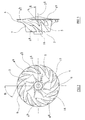
- the backsweep of the impeller blades 4 is also apparent from Figure 2 and Figure 3.
- the angle of backsweep is measured between a radial line extending through the axis of the impeller and a line extending at a tangent to the blade surface at a given point, and lying in a plane normal to the axis (i.e. parallel to the back plate 17).
- the backsweep angle B measured at the tip of a blade is shown. Due to curvature of each blade, the backsweep angle may vary along the surface of the blade but for conventional turbocharger compressors the backsweep angle at any point of the surface of the blade typically lies between 30° to 40°. However, with the present invention the backsweep angle measures at any point on the surface of the blade that lies in the range of 45° to 55°.
- Figure 2 and in particular Figure 3 also illustrate the rake angle of the impeller blades 4.
- the rake angle of a blade at any point on the blade surface can be measured between a line parallel to the axis of the impeller and a line tangential to the blade at that point in a direction defined by a radial cross-section through the blade. Because of the typical curvature of the impeller blades 5, the rake angle may change across the surface of a blade.
- Figure 3 illustrates the rake angle R measured at the tip of a blade 5.
- Conventional turbocharger compressors typically have a back rake angle between 0° and 35°. Compressors in accordance with the present invention may have a back rake angle within this range, but it is preferred that the back rake angle is in the range of 35° to 55°.
- Figure 4 is an over-plot of the performance of a first embodiment of a compressor according to the present invention (the plot shown in dotted lines), in comparison with the performance of a conventional MWE compressor (the plot shown in solid lines).
- the conventional compressor has blades with an average backsweep angle of 40° and a rake angle of 35°.
- the impeller has a squareness of 0.68 and the compressor has a diffuser radius ratio of 1.65.
- Each of the impeller blades of the embodiment of the present invention has an average impeller backsweep angle of about 52° (the backsweep angle varies between 48.5° and 55° across each blade surface).
- the rake angle is substantially constant at 40° (subject to variations due to varying blade thickness).
- the impeller has a squareness of 0.6 and the diffuser radius ratio is 1.52.
- the lower plot is the performance map which, as is well known, plots air flow rate through the compressor against pressure ratio from the compressor inlet to outlet for a variety of impeller rotational speeds.
- the flow axis is normalised to 100%.
- the left hand line of the map represents the flow rates at which the compressor will surge for various turbocharger speeds and is known as the surge line. It can be seen that the compressor according to the present invention has a significantly improved surge margin compared to the surge margin of the conventional compressor. The maximum flow (choke flow) is largely unaffected (shown by the right hand line of the map).
- the surge margin is increased over a range of pressure ratios and in particular is significantly increased at high pressure ratios above 3:1. It can also be seen that the flow capacity of the compressor at maximum operating speed is increased compared with the conventional compressor. Specifically, the surge margin is increased by up to 20% at high pressure ratio, and the pressure ratio capability is increased by up to 15% ratio.
- Superimposed on the compressor map are two engine operating lines L1 and L2. L1 represents the running conditions of a typical conventional turbocharged diesel engine whereas L2 shows the running conditions of a typical turbocharged diesel engine being developed to meet new emission targets. This clearly shows the advantages of the present invention when incorporated in a turbocharger for a diesel engine designed to meet new emission regulations.
- the upper plot of Figure 4 plots the compressor efficiency as a function of air flow. Again, the plot relating to the embodiment of the present invention is shown in dashed lines. It can be seen that at high operating speeds the present invention provides an improvement in efficiency (up to 3% at high pressure ratios).
- Figure 5 is a an over-plot of the compressor map of a second embodiment of the present invention, in comparison with the same conventional MWE compressor as used for the comparison of Figure 4.
- the compressor in accordance with the present invention has impeller blades with a backsweep angle varying between 51° and 55° across each blades surface giving an average backsweep angle of about 53°.
- the rake angle is substantially constant at 35°.
- the impeller has a squareness of 0.63 and the compressor diffuser radius ratio is 1.4.
- surge margin is improved by up to 30%
- pressure ratio capability is improved by up to 7%
- efficiency at high pressure ratio is increased by up to 5%.
- compressors according to the present invention have particular utility as part of a turbocharger, other applications will be apparent to the readily skilled person. Similarly, possible modifications to the detailed structure as described above will be readily apparent to the appropriately skilled person.
Landscapes
- Engineering & Computer Science (AREA)
- Mechanical Engineering (AREA)
- General Engineering & Computer Science (AREA)
- Chemical & Material Sciences (AREA)
- Combustion & Propulsion (AREA)
- Structures Of Non-Positive Displacement Pumps (AREA)
Abstract
Description
wherein the ratio of the impeller inducer diameter to the impeller outer diameter is in the range 0.59 to 0.63;
and wherein the ratio of the diffuser outlet diameter to the impeller outer diameter is between 1.4 and 1.55.
Claims (8)
- A compressor for compressing a gas, the compressor comprising:wherein the angle of backsweep at any point on a blade surface is in the range 45° to 55°;an impeller mounted for rotation about an axis within a chamber defined by a housing;the housing having an axial intake and an annular outlet volute;the chamber having an axial inlet and an annular outlet;said axial inlet being defined by a tubular inducer portion of the housing and said annular outlet being defined by an annular diffuser passage surrounding the impeller, the diffuser having an annular outlet communicating with the outlet volute;the impeller comprising a plurality of blades each having a front edge rotating within the housing inducer portion, a tip sweeping across the annular inlet of the diffuser, and a curved edge defined between the front edge and the tip which sweeps across a surface of the housing defined between the inducer and the diffuser;the impeller having an inducer diameter defined by the outer diameter of the front edges of the blades, and an outer diameter defined by the outer diameter of the blade tips;each blade being backswept relative to the direction of rotation of the impeller about said axis;
wherein the ratio of the impeller inducer diameter to the impeller outer diameter is in the range 0.59 to 0.63;
and wherein the ratio of the diffuser outlet diameter to the impeller outer diameter is between 1.4 and 1.55. - A compressor according to claim 1, wherein the angle of backsweep is between 48° and 55°.
- A compressor according to claim 1 or claim 2, wherein the average angle of backsweep measured across the surface of a blade is in the range of 50° to 55°.
- A compressor according to claim 1 or claim 2, wherein each blade is raked backwards relative to the direction of rotation of the impeller about said axis.
- A compressor according to claim 4, wherein the angle of back rake measured at any point on the surface of a blade is in the range of 35° to 55°.
- A compressor according to claim 5, wherein the angle of back rake of each blade is substantially constant.
- A compressor according to claim 6, wherein the angle of rake is in the range of 35° to 40°.
- A compressor according to any preceding claim, wherein the housing defines an inlet comprising an outer tubular wall extending away from the impeller in an upstream direction forming a gas intake portion of the inlet, and an inner tubular wall extending away from the impeller in an upstream direction within the outer tubular wall and defining said inducer portion of the housing;
an annular gas flow passage being defined between the inner and outer tubular walls and having an upstream end and a downstream end, the upstream end of the annular passage communicating with the intake or inducer portions of the inlet through at least one upstream aperture, the downstream end of the annular flow passage communicating with said surface of the housing swept by the curved edges of the impeller blades through at least one downstream aperture.
Applications Claiming Priority (2)
| Application Number | Priority Date | Filing Date | Title |
|---|---|---|---|
| GB0403869 | 2004-02-21 | ||
| GBGB0403869.1A GB0403869D0 (en) | 2004-02-21 | 2004-02-21 | Compressor |
Publications (3)
| Publication Number | Publication Date |
|---|---|
| EP1566549A2 true EP1566549A2 (en) | 2005-08-24 |
| EP1566549A3 EP1566549A3 (en) | 2009-11-18 |
| EP1566549B1 EP1566549B1 (en) | 2012-09-26 |
Family
ID=32040131
Family Applications (1)
| Application Number | Title | Priority Date | Filing Date |
|---|---|---|---|
| EP05250925A Expired - Lifetime EP1566549B1 (en) | 2004-02-21 | 2005-02-18 | Compressor |
Country Status (6)
| Country | Link |
|---|---|
| US (2) | US20050196272A1 (en) |
| EP (1) | EP1566549B1 (en) |
| JP (1) | JP4717465B2 (en) |
| KR (1) | KR20060043038A (en) |
| CN (1) | CN100443730C (en) |
| GB (1) | GB0403869D0 (en) |
Cited By (1)
| Publication number | Priority date | Publication date | Assignee | Title |
|---|---|---|---|---|
| US20220333613A1 (en) * | 2021-04-19 | 2022-10-20 | Bloom Energy Corporation | Centrifugal blower with integrated motor and blower volute which functions as a heat sink for the motor |
Families Citing this family (43)
| Publication number | Priority date | Publication date | Assignee | Title |
|---|---|---|---|---|
| SE525219C2 (en) * | 2003-05-15 | 2004-12-28 | Volvo Lastvagnar Ab | Turbocharger system for an internal combustion engine where both compressor stages are of radial type with compressor wheels fitted with reverse swept blades |
| CA2432831A1 (en) * | 2003-06-20 | 2004-12-20 | Peter G. Mokry | An impeller and a supercharger for an internal combustion engine |
| WO2009070599A1 (en) * | 2007-11-27 | 2009-06-04 | Emerson Electric Co. | Bi-directional cooling fan |
| EP2279337B1 (en) * | 2008-04-08 | 2017-07-19 | Volvo Lastvagnar AB | Compressor |
| FR2946399B1 (en) * | 2009-06-05 | 2016-05-13 | Turbomeca | CENTRIFUGAL COMPRESSOR WHEEL. |
| CN101994710B (en) * | 2009-08-11 | 2012-05-23 | 珠海格力电器股份有限公司 | Centrifugal compressor with low compression ratio and air conditioning unit using same |
| US8468826B2 (en) * | 2010-04-19 | 2013-06-25 | Honeywell International Inc. | Axial turbine wheel |
| WO2012067320A1 (en) | 2010-11-17 | 2012-05-24 | 한밭대학교 산학협력단 | Vapor compression device using turbo fan and method thereof |
| US20130200218A1 (en) * | 2012-02-08 | 2013-08-08 | Bong H. Suh | Rotorcraft escape system |
| US8997486B2 (en) | 2012-03-23 | 2015-04-07 | Bullseye Power LLC | Compressor wheel |
| JP2014001687A (en) * | 2012-06-19 | 2014-01-09 | Ihi Corp | Impeller and centrifugal compressor |
| US10337529B2 (en) | 2012-06-20 | 2019-07-02 | Ford Global Technologies, Llc | Turbocharger compressor noise reduction system and method |
| US9303561B2 (en) * | 2012-06-20 | 2016-04-05 | Ford Global Technologies, Llc | Turbocharger compressor noise reduction system and method |
| JP5985329B2 (en) * | 2012-09-21 | 2016-09-06 | 株式会社オティックス | Turbocharger and manufacturing method thereof |
| KR20140114512A (en) * | 2013-03-15 | 2014-09-29 | 현대자동차주식회사 | Centrifugal supercharger and supercharging system for engine |
| GB201308381D0 (en) * | 2013-05-09 | 2013-06-19 | Imp Innovations Ltd | A modified inlet duct |
| US8979026B2 (en) * | 2013-06-04 | 2015-03-17 | Hamilton Sundstrandt Corporation | Air compressor backing plate |
| CN105164427A (en) * | 2013-07-04 | 2015-12-16 | 株式会社Ihi | Compressor impeller, centrifugal compressor, machining method for compressor impeller, and machining apparatus for compressor impeller |
| KR102159581B1 (en) * | 2014-04-15 | 2020-09-24 | 삼성전자주식회사 | Vacuum cleaner |
| KR102280929B1 (en) * | 2014-04-15 | 2021-07-26 | 삼성전자주식회사 | Vacuum cleaner |
| US9890788B2 (en) | 2015-03-09 | 2018-02-13 | Caterpillar Inc. | Turbocharger and method |
| US9810238B2 (en) | 2015-03-09 | 2017-11-07 | Caterpillar Inc. | Turbocharger with turbine shroud |
| US9903225B2 (en) | 2015-03-09 | 2018-02-27 | Caterpillar Inc. | Turbocharger with low carbon steel shaft |
| US9777747B2 (en) | 2015-03-09 | 2017-10-03 | Caterpillar Inc. | Turbocharger with dual-use mounting holes |
| US10006341B2 (en) | 2015-03-09 | 2018-06-26 | Caterpillar Inc. | Compressor assembly having a diffuser ring with tabs |
| US9879594B2 (en) | 2015-03-09 | 2018-01-30 | Caterpillar Inc. | Turbocharger turbine nozzle and containment structure |
| US10066639B2 (en) | 2015-03-09 | 2018-09-04 | Caterpillar Inc. | Compressor assembly having a vaneless space |
| US9683520B2 (en) | 2015-03-09 | 2017-06-20 | Caterpillar Inc. | Turbocharger and method |
| US9822700B2 (en) | 2015-03-09 | 2017-11-21 | Caterpillar Inc. | Turbocharger with oil containment arrangement |
| US9752536B2 (en) | 2015-03-09 | 2017-09-05 | Caterpillar Inc. | Turbocharger and method |
| US9650913B2 (en) | 2015-03-09 | 2017-05-16 | Caterpillar Inc. | Turbocharger turbine containment structure |
| US9915172B2 (en) | 2015-03-09 | 2018-03-13 | Caterpillar Inc. | Turbocharger with bearing piloted compressor wheel |
| US9732633B2 (en) | 2015-03-09 | 2017-08-15 | Caterpillar Inc. | Turbocharger turbine assembly |
| US9739238B2 (en) | 2015-03-09 | 2017-08-22 | Caterpillar Inc. | Turbocharger and method |
| US9638138B2 (en) | 2015-03-09 | 2017-05-02 | Caterpillar Inc. | Turbocharger and method |
| WO2017027701A1 (en) * | 2015-08-11 | 2017-02-16 | Carrier Corporation | Low-capacity, low-gwp, hvac system |
| CN105201905B (en) * | 2015-10-16 | 2018-09-11 | 珠海格力电器股份有限公司 | Centrifugal impeller assembly and centrifugal compressor |
| US10221858B2 (en) | 2016-01-08 | 2019-03-05 | Rolls-Royce Corporation | Impeller blade morphology |
| US10718222B2 (en) * | 2017-03-27 | 2020-07-21 | General Electric Company | Diffuser-deswirler for a gas turbine engine |
| US11053950B2 (en) | 2018-03-14 | 2021-07-06 | Carrier Corporation | Centrifugal compressor open impeller |
| GB2576565B (en) * | 2018-08-24 | 2021-07-14 | Rolls Royce Plc | Supercritical carbon dioxide compressor |
| GB201813819D0 (en) * | 2018-08-24 | 2018-10-10 | Rolls Royce Plc | Turbomachinery |
| CN109162960A (en) * | 2018-09-03 | 2019-01-08 | 中国科学院高能物理研究所 | A kind of 2K cold compressor impeller |
Family Cites Families (34)
| Publication number | Priority date | Publication date | Assignee | Title |
|---|---|---|---|---|
| GB544440A (en) | 1939-07-05 | 1942-04-14 | Alessandro Baj | Improvements in centrifugal compressors for supercharging internal combustion engines |
| GB578190A (en) * | 1941-11-21 | 1946-06-19 | Frank Bernard Halford | Improvements in or relating to rotary compressors |
| US3019963A (en) * | 1955-07-08 | 1962-02-06 | Eck Bruno Christian | Radial blower for gases with high dust content |
| US3107046A (en) * | 1958-07-18 | 1963-10-15 | Richardsons Westgarth & Co | Turbines, blowers and the like |
| GB940922A (en) | 1961-07-20 | 1963-11-06 | Davidson & Co Ltd | Improvements in or relating to fans |
| CH616728A5 (en) * | 1975-07-31 | 1980-04-15 | Le Polt I Im M I Kalinina | Radial-flow compressor. |
| DE2830358C2 (en) * | 1978-07-11 | 1984-05-17 | MTU Motoren- und Turbinen-Union München GmbH, 8000 München | Compressor impeller, in particular radial compressor impeller for turbo machines |
| EP0072177B1 (en) * | 1981-08-07 | 1987-01-07 | Holset Engineering Company Limited | Impeller for centrifugal compressor |
| US4503684A (en) * | 1983-12-19 | 1985-03-12 | Carrier Corporation | Control apparatus for centrifugal compressor |
| US4834611A (en) * | 1984-06-25 | 1989-05-30 | Rockwell International Corporation | Vortex proof shrouded inducer |
| DE3670347D1 (en) * | 1985-12-24 | 1990-05-17 | Holset Engineering Co | COMPRESSORS. |
| US4721435A (en) * | 1986-04-30 | 1988-01-26 | Borg-Warner Industrial Products | Fluid flow control means for pumps and the like |
| GB2202585B (en) | 1987-03-24 | 1991-09-04 | Holset Engineering Co | Improvements in and relating to compressors |
| CH675279A5 (en) * | 1988-06-29 | 1990-09-14 | Asea Brown Boveri | |
| JPH0212097A (en) * | 1988-06-30 | 1990-01-17 | Toshiba Corp | Method for operating recirculation pump |
| US4930978A (en) * | 1988-07-01 | 1990-06-05 | Household Manufacturing, Inc. | Compressor stage with multiple vented inducer shroud |
| JPH0212097U (en) * | 1988-07-08 | 1990-01-25 | ||
| DE4027174A1 (en) * | 1990-08-28 | 1992-03-05 | Kuehnle Kopp Kausch Ag | MAP STABILIZATION WITH A RADIAL COMPRESSOR |
| US5246335A (en) * | 1991-05-01 | 1993-09-21 | Ishikawajima-Harimas Jukogyo Kabushiki Kaisha | Compressor casing for turbocharger and assembly thereof |
| US5145317A (en) * | 1991-08-01 | 1992-09-08 | Carrier Corporation | Centrifugal compressor with high efficiency and wide operating range |
| DE4141360A1 (en) | 1991-12-14 | 1993-06-17 | Sel Alcatel Ag | RADIAL BLOWER FOR CONVEYING A COMBUSTIBLE GAS MIXTURE |
| GB2319809A (en) | 1996-10-12 | 1998-06-03 | Holset Engineering Co | An enhanced map width compressor |
| JP3794098B2 (en) * | 1997-01-31 | 2006-07-05 | 株式会社デンソー | Centrifugal blower |
| GB9722916D0 (en) * | 1997-10-31 | 1998-01-07 | Holset Engineering Co | Compressor |
| US6164931A (en) * | 1999-12-15 | 2000-12-26 | Caterpillar Inc. | Compressor wheel assembly for turbochargers |
| US6345503B1 (en) * | 2000-09-21 | 2002-02-12 | Caterpillar Inc. | Multi-stage compressor in a turbocharger and method of configuring same |
| US6623239B2 (en) * | 2000-12-13 | 2003-09-23 | Honeywell International Inc. | Turbocharger noise deflector |
| DE10105456A1 (en) * | 2001-02-07 | 2002-08-08 | Daimler Chrysler Ag | Compressors, in particular for an internal combustion engine |
| US6663347B2 (en) * | 2001-06-06 | 2003-12-16 | Borgwarner, Inc. | Cast titanium compressor wheel |
| US6588485B1 (en) * | 2002-05-10 | 2003-07-08 | Borgwarner, Inc. | Hybrid method for manufacturing titanium compressor wheel |
| DE602004001908T2 (en) * | 2003-04-30 | 2007-04-26 | Holset Engineering Co. Ltd., Huddersfield | compressor |
| SE525219C2 (en) | 2003-05-15 | 2004-12-28 | Volvo Lastvagnar Ab | Turbocharger system for an internal combustion engine where both compressor stages are of radial type with compressor wheels fitted with reverse swept blades |
| US6754954B1 (en) * | 2003-07-08 | 2004-06-29 | Borgwarner Inc. | Process for manufacturing forged titanium compressor wheel |
| US6945748B2 (en) * | 2004-01-22 | 2005-09-20 | Electro-Motive Diesel, Inc. | Centrifugal compressor with channel ring defined inlet recirculation channel |
-
2004
- 2004-02-21 GB GBGB0403869.1A patent/GB0403869D0/en not_active Ceased
-
2005
- 2005-02-18 EP EP05250925A patent/EP1566549B1/en not_active Expired - Lifetime
- 2005-02-21 JP JP2005043940A patent/JP4717465B2/en not_active Expired - Fee Related
- 2005-02-21 US US11/061,993 patent/US20050196272A1/en not_active Abandoned
- 2005-02-21 KR KR1020050014251A patent/KR20060043038A/en not_active Withdrawn
- 2005-02-21 CN CNB2005100640210A patent/CN100443730C/en not_active Expired - Lifetime
-
2008
- 2008-04-21 US US12/148,667 patent/US7686586B2/en not_active Expired - Lifetime
Cited By (3)
| Publication number | Priority date | Publication date | Assignee | Title |
|---|---|---|---|---|
| US20220333613A1 (en) * | 2021-04-19 | 2022-10-20 | Bloom Energy Corporation | Centrifugal blower with integrated motor and blower volute which functions as a heat sink for the motor |
| EP4080060A3 (en) * | 2021-04-19 | 2023-01-25 | Bloom Energy Corporation | Centrifugal blower with integrated motor and blower volute which functions as a heat sink for the motor |
| US11976670B2 (en) * | 2021-04-19 | 2024-05-07 | Bloom Energy Corporation | Centrifugal blower with integrated motor and blower volute which functions as a heat sink for the motor |
Also Published As
| Publication number | Publication date |
|---|---|
| CN1657786A (en) | 2005-08-24 |
| US20080232959A1 (en) | 2008-09-25 |
| CN100443730C (en) | 2008-12-17 |
| GB0403869D0 (en) | 2004-03-24 |
| US20050196272A1 (en) | 2005-09-08 |
| US7686586B2 (en) | 2010-03-30 |
| EP1566549B1 (en) | 2012-09-26 |
| KR20060043038A (en) | 2006-05-15 |
| JP4717465B2 (en) | 2011-07-06 |
| EP1566549A3 (en) | 2009-11-18 |
| JP2005233188A (en) | 2005-09-02 |
Similar Documents
| Publication | Publication Date | Title |
|---|---|---|
| EP1566549B1 (en) | Compressor | |
| US7229243B2 (en) | Compressor | |
| US8157516B2 (en) | Compressor wheel housing | |
| JP4317327B2 (en) | Low speed, high compression ratio turbocharger | |
| US7083379B2 (en) | Compressor | |
| CN1191432C (en) | Compressor | |
| US8322138B2 (en) | Compressor | |
| CN101983281B (en) | Compressor | |
| US20130189094A1 (en) | Multistage compressor with improved map width performance | |
| EP2221487B1 (en) | Centrifugal compressor | |
| US20060067829A1 (en) | Backswept titanium turbocharger compressor wheel | |
| US20190219057A1 (en) | Centrifugal compressor with diffuser with throat | |
| US20180163731A1 (en) | Centrifugal compressor and turbocharger | |
| US20060042588A1 (en) | Swirl generator for a radial compressor | |
| CN112443515A (en) | Compressor with ported shroud and noise attenuator for flow recirculation and turbocharger incorporating same | |
| US7942626B2 (en) | Compressor | |
| CN216306325U (en) | Casing assembly capable of adjusting surge width of compressor and turbocharger | |
| JP7381368B2 (en) | twin scroll turbo | |
| JPS6118161Y2 (en) | ||
| WO2025102030A1 (en) | Fan compressor supercharger/water pump |
Legal Events
| Date | Code | Title | Description |
|---|---|---|---|
| PUAI | Public reference made under article 153(3) epc to a published international application that has entered the european phase |
Free format text: ORIGINAL CODE: 0009012 |
|
| AK | Designated contracting states |
Kind code of ref document: A2 Designated state(s): AT BE BG CH CY CZ DE DK EE ES FI FR GB GR HU IE IS IT LI LT LU MC NL PL PT RO SE SI SK TR |
|
| AX | Request for extension of the european patent |
Extension state: AL BA HR LV MK YU |
|
| PUAL | Search report despatched |
Free format text: ORIGINAL CODE: 0009013 |
|
| AK | Designated contracting states |
Kind code of ref document: A3 Designated state(s): AT BE BG CH CY CZ DE DK EE ES FI FR GB GR HU IE IS IT LI LT LU MC NL PL PT RO SE SI SK TR |
|
| AX | Request for extension of the european patent |
Extension state: AL BA HR LV MK YU |
|
| 17P | Request for examination filed |
Effective date: 20100505 |
|
| AKX | Designation fees paid |
Designated state(s): AT BE BG CH CY CZ DE DK EE ES FI FR GB GR HU IE IS IT LI LT LU MC NL PL PT RO SE SI SK TR |
|
| 17Q | First examination report despatched |
Effective date: 20110321 |
|
| GRAP | Despatch of communication of intention to grant a patent |
Free format text: ORIGINAL CODE: EPIDOSNIGR1 |
|
| GRAS | Grant fee paid |
Free format text: ORIGINAL CODE: EPIDOSNIGR3 |
|
| GRAA | (expected) grant |
Free format text: ORIGINAL CODE: 0009210 |
|
| AK | Designated contracting states |
Kind code of ref document: B1 Designated state(s): AT BE BG CH CY CZ DE DK EE ES FI FR GB GR HU IE IS IT LI LT LU MC NL PL PT RO SE SI SK TR |
|
| REG | Reference to a national code |
Ref country code: GB Ref legal event code: FG4D |
|
| REG | Reference to a national code |
Ref country code: CH Ref legal event code: EP |
|
| REG | Reference to a national code |
Ref country code: AT Ref legal event code: REF Ref document number: 577192 Country of ref document: AT Kind code of ref document: T Effective date: 20121015 |
|
| REG | Reference to a national code |
Ref country code: IE Ref legal event code: FG4D |
|
| REG | Reference to a national code |
Ref country code: DE Ref legal event code: R096 Ref document number: 602005036256 Country of ref document: DE Effective date: 20121129 |
|
| PG25 | Lapsed in a contracting state [announced via postgrant information from national office to epo] |
Ref country code: LT Free format text: LAPSE BECAUSE OF FAILURE TO SUBMIT A TRANSLATION OF THE DESCRIPTION OR TO PAY THE FEE WITHIN THE PRESCRIBED TIME-LIMIT Effective date: 20120926 Ref country code: FI Free format text: LAPSE BECAUSE OF FAILURE TO SUBMIT A TRANSLATION OF THE DESCRIPTION OR TO PAY THE FEE WITHIN THE PRESCRIBED TIME-LIMIT Effective date: 20120926 |
|
| REG | Reference to a national code |
Ref country code: AT Ref legal event code: MK05 Ref document number: 577192 Country of ref document: AT Kind code of ref document: T Effective date: 20120926 |
|
| REG | Reference to a national code |
Ref country code: LT Ref legal event code: MG4D Effective date: 20120926 |
|
| REG | Reference to a national code |
Ref country code: NL Ref legal event code: VDEP Effective date: 20120926 |
|
| PG25 | Lapsed in a contracting state [announced via postgrant information from national office to epo] |
Ref country code: GR Free format text: LAPSE BECAUSE OF FAILURE TO SUBMIT A TRANSLATION OF THE DESCRIPTION OR TO PAY THE FEE WITHIN THE PRESCRIBED TIME-LIMIT Effective date: 20121227 Ref country code: SI Free format text: LAPSE BECAUSE OF FAILURE TO SUBMIT A TRANSLATION OF THE DESCRIPTION OR TO PAY THE FEE WITHIN THE PRESCRIBED TIME-LIMIT Effective date: 20120926 Ref country code: SE Free format text: LAPSE BECAUSE OF FAILURE TO SUBMIT A TRANSLATION OF THE DESCRIPTION OR TO PAY THE FEE WITHIN THE PRESCRIBED TIME-LIMIT Effective date: 20120926 |
|
| PG25 | Lapsed in a contracting state [announced via postgrant information from national office to epo] |
Ref country code: CZ Free format text: LAPSE BECAUSE OF FAILURE TO SUBMIT A TRANSLATION OF THE DESCRIPTION OR TO PAY THE FEE WITHIN THE PRESCRIBED TIME-LIMIT Effective date: 20120926 Ref country code: ES Free format text: LAPSE BECAUSE OF FAILURE TO SUBMIT A TRANSLATION OF THE DESCRIPTION OR TO PAY THE FEE WITHIN THE PRESCRIBED TIME-LIMIT Effective date: 20130106 Ref country code: RO Free format text: LAPSE BECAUSE OF FAILURE TO SUBMIT A TRANSLATION OF THE DESCRIPTION OR TO PAY THE FEE WITHIN THE PRESCRIBED TIME-LIMIT Effective date: 20120926 Ref country code: BE Free format text: LAPSE BECAUSE OF FAILURE TO SUBMIT A TRANSLATION OF THE DESCRIPTION OR TO PAY THE FEE WITHIN THE PRESCRIBED TIME-LIMIT Effective date: 20120926 Ref country code: NL Free format text: LAPSE BECAUSE OF FAILURE TO SUBMIT A TRANSLATION OF THE DESCRIPTION OR TO PAY THE FEE WITHIN THE PRESCRIBED TIME-LIMIT Effective date: 20120926 Ref country code: IS Free format text: LAPSE BECAUSE OF FAILURE TO SUBMIT A TRANSLATION OF THE DESCRIPTION OR TO PAY THE FEE WITHIN THE PRESCRIBED TIME-LIMIT Effective date: 20130126 Ref country code: EE Free format text: LAPSE BECAUSE OF FAILURE TO SUBMIT A TRANSLATION OF THE DESCRIPTION OR TO PAY THE FEE WITHIN THE PRESCRIBED TIME-LIMIT Effective date: 20120926 |
|
| PG25 | Lapsed in a contracting state [announced via postgrant information from national office to epo] |
Ref country code: CY Free format text: LAPSE BECAUSE OF FAILURE TO SUBMIT A TRANSLATION OF THE DESCRIPTION OR TO PAY THE FEE WITHIN THE PRESCRIBED TIME-LIMIT Effective date: 20120926 Ref country code: PL Free format text: LAPSE BECAUSE OF FAILURE TO SUBMIT A TRANSLATION OF THE DESCRIPTION OR TO PAY THE FEE WITHIN THE PRESCRIBED TIME-LIMIT Effective date: 20120926 Ref country code: SK Free format text: LAPSE BECAUSE OF FAILURE TO SUBMIT A TRANSLATION OF THE DESCRIPTION OR TO PAY THE FEE WITHIN THE PRESCRIBED TIME-LIMIT Effective date: 20120926 Ref country code: PT Free format text: LAPSE BECAUSE OF FAILURE TO SUBMIT A TRANSLATION OF THE DESCRIPTION OR TO PAY THE FEE WITHIN THE PRESCRIBED TIME-LIMIT Effective date: 20130128 |
|
| PG25 | Lapsed in a contracting state [announced via postgrant information from national office to epo] |
Ref country code: AT Free format text: LAPSE BECAUSE OF FAILURE TO SUBMIT A TRANSLATION OF THE DESCRIPTION OR TO PAY THE FEE WITHIN THE PRESCRIBED TIME-LIMIT Effective date: 20120926 |
|
| PG25 | Lapsed in a contracting state [announced via postgrant information from national office to epo] |
Ref country code: BG Free format text: LAPSE BECAUSE OF FAILURE TO SUBMIT A TRANSLATION OF THE DESCRIPTION OR TO PAY THE FEE WITHIN THE PRESCRIBED TIME-LIMIT Effective date: 20121226 Ref country code: DK Free format text: LAPSE BECAUSE OF FAILURE TO SUBMIT A TRANSLATION OF THE DESCRIPTION OR TO PAY THE FEE WITHIN THE PRESCRIBED TIME-LIMIT Effective date: 20120926 |
|
| PLBE | No opposition filed within time limit |
Free format text: ORIGINAL CODE: 0009261 |
|
| STAA | Information on the status of an ep patent application or granted ep patent |
Free format text: STATUS: NO OPPOSITION FILED WITHIN TIME LIMIT |
|
| PG25 | Lapsed in a contracting state [announced via postgrant information from national office to epo] |
Ref country code: IT Free format text: LAPSE BECAUSE OF FAILURE TO SUBMIT A TRANSLATION OF THE DESCRIPTION OR TO PAY THE FEE WITHIN THE PRESCRIBED TIME-LIMIT Effective date: 20120926 |
|
| 26N | No opposition filed |
Effective date: 20130627 |
|
| PG25 | Lapsed in a contracting state [announced via postgrant information from national office to epo] |
Ref country code: MC Free format text: LAPSE BECAUSE OF NON-PAYMENT OF DUE FEES Effective date: 20130228 |
|
| REG | Reference to a national code |
Ref country code: CH Ref legal event code: PL |
|
| REG | Reference to a national code |
Ref country code: DE Ref legal event code: R097 Ref document number: 602005036256 Country of ref document: DE Effective date: 20130627 |
|
| PG25 | Lapsed in a contracting state [announced via postgrant information from national office to epo] |
Ref country code: CH Free format text: LAPSE BECAUSE OF NON-PAYMENT OF DUE FEES Effective date: 20130228 Ref country code: LI Free format text: LAPSE BECAUSE OF NON-PAYMENT OF DUE FEES Effective date: 20130228 |
|
| REG | Reference to a national code |
Ref country code: IE Ref legal event code: MM4A |
|
| PG25 | Lapsed in a contracting state [announced via postgrant information from national office to epo] |
Ref country code: IE Free format text: LAPSE BECAUSE OF NON-PAYMENT OF DUE FEES Effective date: 20130218 |
|
| PG25 | Lapsed in a contracting state [announced via postgrant information from national office to epo] |
Ref country code: TR Free format text: LAPSE BECAUSE OF FAILURE TO SUBMIT A TRANSLATION OF THE DESCRIPTION OR TO PAY THE FEE WITHIN THE PRESCRIBED TIME-LIMIT Effective date: 20120926 |
|
| PG25 | Lapsed in a contracting state [announced via postgrant information from national office to epo] |
Ref country code: LU Free format text: LAPSE BECAUSE OF NON-PAYMENT OF DUE FEES Effective date: 20130218 Ref country code: HU Free format text: LAPSE BECAUSE OF FAILURE TO SUBMIT A TRANSLATION OF THE DESCRIPTION OR TO PAY THE FEE WITHIN THE PRESCRIBED TIME-LIMIT; INVALID AB INITIO Effective date: 20050218 |
|
| REG | Reference to a national code |
Ref country code: FR Ref legal event code: PLFP Year of fee payment: 12 |
|
| REG | Reference to a national code |
Ref country code: FR Ref legal event code: PLFP Year of fee payment: 13 |
|
| REG | Reference to a national code |
Ref country code: FR Ref legal event code: PLFP Year of fee payment: 14 |
|
| PGFP | Annual fee paid to national office [announced via postgrant information from national office to epo] |
Ref country code: FR Payment date: 20200225 Year of fee payment: 16 |
|
| PG25 | Lapsed in a contracting state [announced via postgrant information from national office to epo] |
Ref country code: FR Free format text: LAPSE BECAUSE OF NON-PAYMENT OF DUE FEES Effective date: 20210228 |
|
| P01 | Opt-out of the competence of the unified patent court (upc) registered |
Effective date: 20230510 |
|
| PGFP | Annual fee paid to national office [announced via postgrant information from national office to epo] |
Ref country code: DE Payment date: 20240228 Year of fee payment: 20 Ref country code: GB Payment date: 20240227 Year of fee payment: 20 |
|
| REG | Reference to a national code |
Ref country code: DE Ref legal event code: R071 Ref document number: 602005036256 Country of ref document: DE |
|
| REG | Reference to a national code |
Ref country code: GB Ref legal event code: PE20 Expiry date: 20250217 |
|
| PG25 | Lapsed in a contracting state [announced via postgrant information from national office to epo] |
Ref country code: GB Free format text: LAPSE BECAUSE OF EXPIRATION OF PROTECTION Effective date: 20250217 |