EP1566323B1 - Linear tracking column module - Google Patents
Linear tracking column module Download PDFInfo
- Publication number
- EP1566323B1 EP1566323B1 EP05075130A EP05075130A EP1566323B1 EP 1566323 B1 EP1566323 B1 EP 1566323B1 EP 05075130 A EP05075130 A EP 05075130A EP 05075130 A EP05075130 A EP 05075130A EP 1566323 B1 EP1566323 B1 EP 1566323B1
- Authority
- EP
- European Patent Office
- Prior art keywords
- steering
- assembly
- bracket
- tubes
- bolster
- Prior art date
- Legal status (The legal status is an assumption and is not a legal conclusion. Google has not performed a legal analysis and makes no representation as to the accuracy of the status listed.)
- Expired - Lifetime
Links
- 230000007246 mechanism Effects 0.000 claims abstract description 56
- 230000004044 response Effects 0.000 claims abstract description 18
- 210000003127 knee Anatomy 0.000 claims description 23
- 239000006096 absorbing agent Substances 0.000 claims description 6
- 230000000712 assembly Effects 0.000 description 5
- 238000000429 assembly Methods 0.000 description 5
- 238000005452 bending Methods 0.000 description 3
- 230000000977 initiatory effect Effects 0.000 description 2
- 230000002452 interceptive effect Effects 0.000 description 1
- 239000000463 material Substances 0.000 description 1
- 230000004048 modification Effects 0.000 description 1
- 238000012986 modification Methods 0.000 description 1
- 230000002093 peripheral effect Effects 0.000 description 1
Images




Classifications
-
- B—PERFORMING OPERATIONS; TRANSPORTING
- B60—VEHICLES IN GENERAL
- B60R—VEHICLES, VEHICLE FITTINGS, OR VEHICLE PARTS, NOT OTHERWISE PROVIDED FOR
- B60R21/00—Arrangements or fittings on vehicles for protecting or preventing injuries to occupants or pedestrians in case of accidents or other traffic risks
- B60R21/02—Occupant safety arrangements or fittings, e.g. crash pads
- B60R21/09—Control elements or operating handles movable from an operative to an out-of-the way position, e.g. pedals, switch knobs, window cranks
-
- B—PERFORMING OPERATIONS; TRANSPORTING
- B60—VEHICLES IN GENERAL
- B60T—VEHICLE BRAKE CONTROL SYSTEMS OR PARTS THEREOF; BRAKE CONTROL SYSTEMS OR PARTS THEREOF, IN GENERAL; ARRANGEMENT OF BRAKING ELEMENTS ON VEHICLES IN GENERAL; PORTABLE DEVICES FOR PREVENTING UNWANTED MOVEMENT OF VEHICLES; VEHICLE MODIFICATIONS TO FACILITATE COOLING OF BRAKES
- B60T7/00—Brake-action initiating means
- B60T7/02—Brake-action initiating means for personal initiation
- B60T7/04—Brake-action initiating means for personal initiation foot actuated
- B60T7/06—Disposition of pedal
- B60T7/065—Disposition of pedal with means to prevent injuries in case of collision
-
- B—PERFORMING OPERATIONS; TRANSPORTING
- B62—LAND VEHICLES FOR TRAVELLING OTHERWISE THAN ON RAILS
- B62D—MOTOR VEHICLES; TRAILERS
- B62D1/00—Steering controls, i.e. means for initiating a change of direction of the vehicle
- B62D1/02—Steering controls, i.e. means for initiating a change of direction of the vehicle vehicle-mounted
- B62D1/16—Steering columns
- B62D1/18—Steering columns yieldable or adjustable, e.g. tiltable
- B62D1/19—Steering columns yieldable or adjustable, e.g. tiltable incorporating energy-absorbing arrangements, e.g. by being yieldable or collapsible
- B62D1/195—Yieldable supports for the steering column
-
- B—PERFORMING OPERATIONS; TRANSPORTING
- B60—VEHICLES IN GENERAL
- B60R—VEHICLES, VEHICLE FITTINGS, OR VEHICLE PARTS, NOT OTHERWISE PROVIDED FOR
- B60R21/00—Arrangements or fittings on vehicles for protecting or preventing injuries to occupants or pedestrians in case of accidents or other traffic risks
- B60R2021/003—Arrangements or fittings on vehicles for protecting or preventing injuries to occupants or pedestrians in case of accidents or other traffic risks characterised by occupant or pedestian
- B60R2021/0039—Body parts of the occupant or pedestrian affected by the accident
- B60R2021/0051—Knees
Definitions
- the subject invention relates to a vehicle steering assembly having components movable in response to a crash condition.
- Collapsible steering column assemblies are well known in the art. Such assemblies typically include an energy-absorbing bracket or other support affixed to the body of a vehicle. Steering column components including, but not limited to a steering wheel and shaft are carried by the support. Should a collision occur in which a sufficiently large impact force is applied to the steering wheel, the steering column and wheel will collapse relative to the support and translate away from the driver of the vehicle.
- the collapse of the column typically takes place along the axis of the column, which may not correspond to a preferred collapse path, but for design limitations of the column.
- a collapsible steering assembly according to the preamble of claim 1 is known from US-A-6149196 .
- the present invention provides a collapsible steering assembly including a stationary guide bracket for attachment to a vehicle and a steering mechanism having a longitudinal axis.
- the assembly also features a steering mechanism support with a plurality of guide rods arranged about a common collapse axis.
- the guide rods not only interconnect the guide bracket and the steering mechanism, but also support the steering mechanism for axial movement along the collapse axis in response to application of a predetermined collapse force to the steering mechanism.
- the subject invention addresses the shortcomings of the prior assemblies through the provision of guide rods which interconnect the steering mechanism and associated guide bracket with a steering mechanism support, providing a modular, robust assembly which enables the steering mechanism to be supported during normal operation about one axis best suited for operation of the steering mechanism, while further supporting the assembly for collapse along a collapse path different than that of the steering mechanism axis.
- the steering mechanism moves simultaneously with the guide rods relative to the guide bracket to enable the steering mechanism to collapse along the collapse path other than that of the axis of the steering mechanism.
- the guide rods are preferably oriented independently of the axis of the steering mechanism to cause the steering mechanism to collapse in a direction corresponding to an ideal trajectory path of the upper torso of a driver in a collision to maximize the energy absorbed by the assembly.
- the guide rods are also preferably spaced from one another to provide a stable framework that resists any bending or deformation of the support structure during collapse.
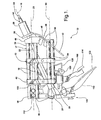
- a collapsible steering assembly is generally shown at 10 in Figure 1 .
- the assembly 10 includes a stationary guide bracket 12 for attachment to a vehicle and a steering mechanism 14 having a longitudinal steering mechanism axis 16.
- the assembly 10 also includes a steering mechanism support 17 with a plurality of guide rods 18 .
- the guide rods 18 are arranged about a common collapse axis 20 in non-parallel relationship to the steering mechanism axis 16 , and interconnect the guide bracket 12 and the steering mechanism 14 .
- the guide rods 18 also support the steering mechanism 14 for axial movement along the collapse axis 20 in response to application of a predetermined collapse force to the steering mechanism 14 .
- the steering mechanism 14 includes a steering shaft 22 .
- the shaft 22 extends coaxially with the steering mechanism axis 16 between upper and lower ends 24 and 26 .
- An upper bearing housing 28 and a rake bracket 30 are coaxially disposed about the shaft 22 adjacent the upper end 26.
- a lower bearing housing 32 is coaxially disposed about the shaft 22 adjacent the lower end 24 .
- the steering mechanism 14 shown in Figure 1 comprises a conventional steering column with a shaft 22, those skilled in the art will appreciate that the steering mechanism 14 used in the assembly 10 need not be limited to one utilizing a traditional column structure.
- the steering mechanism 14 may, for example, comprise a steer-by-wire system which may or may not include a mechanical steering linkage such as the shaft 22 .
- the assembly 10 also includes a plurality of steering shear elements 34 that interconnect the guide rods 18 and the guide bracket 12.
- the shear elements 34 operate to prevent movement of the steering mechanism 14 relative to the guide bracket 12 during normal useage of the assembly 10 , but are shearable in response to application of the predetermined collapse force on the steering mechanism 14 to enable the guide rods 18 and the steering mechanism 14 to move relative to the guide bracket 12 along the collapse axis 20.
- the guide bracket 12 supports the guide rods 18 in fixed relationship to one another, which in turn permits collective movement of the guide rods 18 relative to the guide bracket 12 in response to the predetermined collapse force on the steering mechanism 14.
- each guide rod 18 shown in Figure 1 is preferably straight and comprises a steering tube having a front end 36 and a rear end 38 .
- the steering tubes 18 of the present invention preferably include four tubes spaced from one another in a quadrangle.
- a front bracket 40 interconnects the front ends 36 of the steering tubes 18, and a rear bracket 42 supports the rear ends 38 of the steering tubes 18 and the steering mechanism 14 .
- the front and rear brackets 40 and 42 are spaced on opposite sides of the guide bracket 12, such that the guide bracket 12 is located along the steering tubes 18 between the front and rear brackets 40 and 42.
- a second plurality of steering shear elements 34 interconnect the rear bracket 42 and the steering tubes 18.
- the steering shear elements 34 normally prevent movement of the steering tubes 18 relative to the rear bracket 42 , but shear in response to application of the predetermined collapse force to the steering mechanism 14 f or allowing the steering tubes 18 to move through the rear bracket 42 in the same manner as the shear elements associated with the guide bracket 12.
- the rear ends 38 of the steering tubes 18 preferably extend through the rear bracket 42 .
- the front bracket 40 includes a central opening 44 and a peripheral edge 46 from which a collar 48 extends.
- the upper end 24 of the steering shaft 22 , the upper bearing housing 28 , and the rake bracket 30 extend through the opening 44 .
- the lower end 26 of the steering shaft 22 extends beyond the rear bracket 42, such that the front bracket 40 , guide bracket 12 and rear bracket 42 are spaced along the steering shaft 22 between the upper and lower ends 24 and 26.
- the rear bracket 42 includes at least one and preferably two connectors 50 for attachment to the vehicle.
- the guide bracket 12 likewise includes at least one and preferably two connectors 50 for attachment to the vehicle. Each connector 50 may be formed with a hole 51 or other feature for receiving a fastening bolt (not shown) to permit attachment to the vehicle.
- the assembly 10 also includes a knee bolster 52 for absorbing impact energy during a crash condition.
- a plurality of bolster guide rods 54 are arranged about a second collapse axis 55 and interconnect the guide bracket 12 and the knee bolster 52.
- the bolster guide rods 54 support the knee bolster 52 for axial movement along the second collapse axis 55 in response to application of a second predetermined collapse force to the knee bolster 52.
- a plurality of bolster shear elements 56 interconnect the bolster guide rods 54 and the guide bracket 12.
- the bolster shear elements 56 prevent the knee bolster 52 from moving relative to the guide bracket 12 during normal operation but are operative to shear in response to application of an applied collapse force to the knee bolster 52 sufficient to overcome the holding force of the shear elements 56, which in turn allows the bolster guide rods 54 and the knee bolster 52 to move relative to the guide bracket 12 in a collapse event.
- each of the bolster guide rods 54 may have any suitable shape
- each bolster guide rod 54 is preferably straight and comprises a tube having a front end 58 and a rear end 60. Any number of bolster guide rods, or bolster tubes, 54 may be utilized and arranged in any suitable configuration relative to the guide bracket 12.
- the bolster tubes 54 of the present invention preferably include four such tubes spaced from one another in a quadrangle.
- the guide bracket 12 includes an upper block 62 having bores 64 therethrough.
- the steering tubes 18 extend through the bores 64.
- the guide bracket 12 also includes a lower block 66 having bores 68 therethrough.
- the bolster tubes 54 extend through the bores 68 in the lower block 66 .
- the steering shear elements 34 and bolster shear elements 56 of the present invention preferably comprise bushings.
- Each bushing is interposed between one of the tubes 18 or 54 and one of either the guide bracket 12 or the rear bracket 42 and has a detent or other feature which maintains the tube 18 or 54 in a fixed position relative to the guide bracket 12 or the rear bracket 42 during normal operation.
- the bolster tubes 54 of the assembly 10 are disposed in at least one pair on either side of the steering tubes 18 .
- the bolster tubes 54 are also disposed parallel to the steering tubes 18 .
- Two pairs of bolster tubes 54 are disclosed, and each pair extends through the bores 68 in the lower block 66.
- the rear ends 60 of the bolster tubes 54 are supported by the rear bracket 42. Disposing the bolster tubes 54 outside the steering tubes 18 permits the knee bolster 52 to collapse without interfering with or otherwise initiating a simultaneous or subsequent collapse of the steering tubes 18 and steering mechanism 14 .
- the assembly 10 also includes an energy absorber system 70 for absorbing energy during movement of the steering mechanism 14 and knee bolster 52 relative to the guide bracket 12.
- the energy absorber system 70 includes a first anvil-strap device 72 interconnecting the steering tubes 18 and upper block 62.
- the first anvil-strap device 72 includes a release bracket 74 with bores 76 therethrough.
- the release bracket 74 is disposed in engagement with the upper block 62 .
- the steering tubes 18 extend through the bores 76 and are carried by the release bracket 74 in fixed relation to one another.
- the at least one and preferably two pair of plastically-deformable straps 78 with holes 80 therethrough are disposed in frictional and bending engagement with respective pairs of first and second anvils 82 and 84 .
- the straps 78 interconnect the release bracket 74 with the upper block 62 .
- Each pair of straps 78 includes a high-force strap 86 and a low-force strap 88 extending in parallel relation to one another from the release bracket 74 .
- Retaining pins 90 are disposed within the release bracket 74 .
- Each pin 90 extends through one of the holes 80 and interconnects the associated strap 86 or 88 with the release bracket 74 .
- the pins 90 may alternatively be disposed within the upper block 62 for securing the straps 86 and 88 with the upper block 62 .
- the first anvil-strap device 72 is a variable energy absorbing system that utilizes pairs of S-straps having variable widths.
- energy absorbing devices including but not limited to those which employ one or more M-straps, J-straps, other straps, wires, pyrotechnic or other actuating devices, or a combination thereof.
- the first anvil strap device 72 also includes actuating devices 100, which are disposed upon threaded bosses 102 that extend from the release bracket 74. Each actuating device 100 engages one of the pins 90 and selectively discharges for actuating movement of the pin 90 to a discharged position "P 1 ", such as that which is shown in Figure 4 . This alters the frictional and/or bending or resistance force generated by the strap 86 or 88 associated with the pin 90 as the straps 86 and 88 move across the anvils 82 and 84, respectively, to correspondingly alter the energy absorbing characteristics of the energy absorber system 70.
- Each pair of anvils 82 and 84 displaces a portion of the pair of straps 86 and 88 associated therewith and imposes a reaction force thereon to absorb energy as each pair of the straps 86 and 88 move past the respective pairs of anvils 82 and 84.
- the preferred actuating device 100 comprises an electrically activated pyrotechnic device.
- a control system such as that which is schematically depicted at 104 in Figure 4 is operatively connected to the devices 100 .
- the control system 104 monitors and detects variable components affected by the crash condition, determines the amount of energy to be absorbed, and transmits a signal corresponding to that amount to the actuating devices 100, which in turn actuates one or more of the devices 100 to modify the energy absorbing characteristics in accordance with the requirements of a particular crash event.
- the actuating devices 100 may initiate release of the low-force straps 88 to provide corresponding reduced energy absorbing characteristics of the system 104. Under still lesser crash conditions, the actuating devices 100 may respond to by initiating release of the high-force straps 86 to produce a correspondingly reduced energy absorbing characteristic of the system 104 .
- the energy absorber system 70 also includes a second anvil strap device 142 associated with the knee bolster 52.
- the second anvil strap device 142 includes many of the same components and functions in the same manner as the first anvil-strap device 72.
- the second anvil-strap device 142 includes a release bracket 144 which disposed against the lower block 66 during normal operation.
- the bolster tubes 54 are carried by the release bracket 144 in fixed relation to one another.
- a pair of energy absorbing straps 146 interconnect the release bracket 144 with the lower block 66.
- the high and low-force straps 148 and 150 of the pair 146 are secured by retaining pins 152 to the upper surface 154 of the release bracket 144 .
- the pins 152 will release one or both of the straps 148 and 150 upon being actuated in response to a signal transmitted from the control system 104 to absorb energy in response to application of the predetermined collapse force on the knee bolster 52 .
- any other suitable energy-absorbing device or devices may be used in place of the second anvil-strap device 142.
- a hinge assembly 92 extends from the release bracket 74.
- the hinge assembly 92 may be used for attaching an optional display screen or other control device (not shown) to the assembly 10.
- a lower bearing housing support 94 is also disposed on the release bracket 74.
- the support 94 has two arms that extend at an angle from the release bracket 74 to a connecting end 96 through which a hole 98 extends.
- a pivot pin (not shown) is disposed through the hole 98 and engages the lower bearing housing 94 for permitting pivotal movement of the steering mechanism 14 relative to the guide bracket 12.
- the assembly 10 also includes a pedal assembly, which is generally shown at 106 in Figure 7 .
- the pedal assembly 106 is pivotally connected to the rear bracket 42 for pivotal movement in response to movement of the steering tubes 18 relative to the rear bracket 42.
- the pedal assembly 106 includes a brake assembly 108 and a throttle assembly 110 .
- a mounting assembly 112 interconnects the brake and throttle assemblies 108 and 110 with the rear bracket 42 .
- the brake assembly 106 includes a brake pedal 114.
- a first bracket 116 interconnects the brake pedal 114 and the mounting bracket 112.
- the first bracket 116 includes a slot 118 .
- Adjustment fasteners 120 adjustably mount the brake pedal 114 in the slot 118 for permitting adjustment of the position of the brake pedal 114 relative to the first bracket 116 .
- the throttle assembly 110 includes a throttle pedal 122.
- a second bracket 124 interconnects the throttle pedal 122 and the mounting bracket 112.
- An adjustment fastener 128 adjustably mounts the throttle pedal 122 in the a slot 126 for adjusting the throttle pedal 122 relative to the second bracket 124 .
- the pedal assembly 106 also includes a hinge assembly 130 that interconnects the mounting bracket 112 and the rear bracket 42 and permits pivotal movement of the pedal assembly 106 .
- the hinge assembly 130 features a bifurcated bracket 132 that carries the mounting bracket 112 .
- the pedal assembly 106 also includes a motor 156 having drive cables 158 operatively connected to at least one pedal actuator 160 carried by the mounting assembly 112.
- the pedal actuator 160 selectively actuates movement of the brake and throttle assemblies 108 and 110 .
- the bifurcated bracket 132 includes a pair of screw bosses 162 through which screws extend (not shown) for securing the bracket 132 to the mounting assembly 112 .
- the pedal assembly 106 also includes a release mechanism 164 , which has a pair of pyrotechnic bosses 166 defining chambers 168.
- a pyrotechnic pin 170 is disposed within the rear bracket 42 and communicates with at least one of the chambers 168 .
- pyrotechnic devices 172 are disposed on the bosses 168. Actuating the devices 172 causes the pyrotechnic pin 170 to fire, which in turn causes the bifurcated bracket 132 to pivot away from the rear bracket 42.
Landscapes
- Engineering & Computer Science (AREA)
- Mechanical Engineering (AREA)
- Transportation (AREA)
- Chemical & Material Sciences (AREA)
- Combustion & Propulsion (AREA)
- Steering Controls (AREA)
Abstract
Description
- The subject invention relates to a vehicle steering assembly having components movable in response to a crash condition.
- Collapsible steering column assemblies are well known in the art. Such assemblies typically include an energy-absorbing bracket or other support affixed to the body of a vehicle. Steering column components including, but not limited to a steering wheel and shaft are carried by the support. Should a collision occur in which a sufficiently large impact force is applied to the steering wheel, the steering column and wheel will collapse relative to the support and translate away from the driver of the vehicle.
- The collapse of the column typically takes place along the axis of the column, which may not correspond to a preferred collapse path, but for design limitations of the column.
- A collapsible steering assembly according to the preamble of claim 1 is known from
US-A-6149196 . - It is an object of the invention to provide a column assembly which overcomes the limitations of the prior columns in a form that is both readily acceptable to particular design requirements of a given application and is robust.
- This object is satisfied by a collapsible steering assembly in accordance with claim 1.
- The present invention provides a collapsible steering assembly including a stationary guide bracket for attachment to a vehicle and a steering mechanism having a longitudinal axis. The assembly also features a steering mechanism support with a plurality of guide rods arranged about a common collapse axis. The guide rods not only interconnect the guide bracket and the steering mechanism, but also support the steering mechanism for axial movement along the collapse axis in response to application of a predetermined collapse force to the steering mechanism.
- The subject invention addresses the shortcomings of the prior assemblies through the provision of guide rods which interconnect the steering mechanism and associated guide bracket with a steering mechanism support, providing a modular, robust assembly which enables the steering mechanism to be supported during normal operation about one axis best suited for operation of the steering mechanism, while further supporting the assembly for collapse along a collapse path different than that of the steering mechanism axis. In a crash event, the steering mechanism moves simultaneously with the guide rods relative to the guide bracket to enable the steering mechanism to collapse along the collapse path other than that of the axis of the steering mechanism. In particular, the guide rods are preferably oriented independently of the axis of the steering mechanism to cause the steering mechanism to collapse in a direction corresponding to an ideal trajectory path of the upper torso of a driver in a collision to maximize the energy absorbed by the assembly. The guide rods are also preferably spaced from one another to provide a stable framework that resists any bending or deformation of the support structure during collapse.
- Other advantages of the present invention will be readily appreciated as the same becomes better understood by reference to the following detailed description when considered in connection with the accompanying drawings wherein:
-
Figure 1 is a side view of a collapsible steering assembly according to an embodiment of the present invention; -
Figure 2 is a front perspective view of the collapsible steering assembly shown inFigure 1 with the steering assembly, knee bolster and pedal assembly removed; -
Figure 3 is a rear perspective view of the collapsible steering assembly shown inFigure 2 ; -
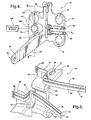
Figure 4 is a perspective view of the release bracket and lower bearing housing support utilized in the collapsible steering assembly with one arm of the lower bearing housing support removed; -
Figure 5 is a partial perspective view of the upper block and pairs of high force and low-force straps of one of the anvil-strap devices utilized in the steering assembly; -
Figure 6 is a partial cross-sectional view of a pair of pyrotechnic devices and pyrotechnic pins utilized in the anvil-strap device shown inFigure 4 ; -
Figure 7 is a perspective view of the pedal assembly, steering tubes and bolster tubes of the collapsible steering assembly; and -
Figure 8 is a partial perspective view of the pedal hinge assembly and actuating device associated therewith of the collapsible steering assembly. - Referring to the Figures, wherein like numerals indicate like or corresponding parts throughout the several views, a collapsible steering assembly is generally shown at 10 in
Figure 1 . Theassembly 10 includes astationary guide bracket 12 for attachment to a vehicle and asteering mechanism 14 having a longitudinalsteering mechanism axis 16. Theassembly 10 also includes a steering mechanism support 17 with a plurality ofguide rods 18. Theguide rods 18 are arranged about acommon collapse axis 20 in non-parallel relationship to thesteering mechanism axis 16, and interconnect theguide bracket 12 and thesteering mechanism 14. Theguide rods 18 also support thesteering mechanism 14 for axial movement along thecollapse axis 20 in response to application of a predetermined collapse force to thesteering mechanism 14. - The
steering mechanism 14 includes asteering shaft 22. Theshaft 22 extends coaxially with thesteering mechanism axis 16 between upper andlower ends housing 28 and arake bracket 30 are coaxially disposed about theshaft 22 adjacent theupper end 26. A lower bearinghousing 32 is coaxially disposed about theshaft 22 adjacent thelower end 24. - Although the
steering mechanism 14 shown inFigure 1 comprises a conventional steering column with ashaft 22, those skilled in the art will appreciate that thesteering mechanism 14 used in theassembly 10 need not be limited to one utilizing a traditional column structure. Thesteering mechanism 14 may, for example, comprise a steer-by-wire system which may or may not include a mechanical steering linkage such as theshaft 22. - The
assembly 10 also includes a plurality ofsteering shear elements 34 that interconnect theguide rods 18 and theguide bracket 12. Theshear elements 34 operate to prevent movement of thesteering mechanism 14 relative to theguide bracket 12 during normal useage of theassembly 10, but are shearable in response to application of the predetermined collapse force on thesteering mechanism 14 to enable theguide rods 18 and thesteering mechanism 14 to move relative to theguide bracket 12 along thecollapse axis 20. Theguide bracket 12 supports theguide rods 18 in fixed relationship to one another, which in turn permits collective movement of theguide rods 18 relative to theguide bracket 12 in response to the predetermined collapse force on thesteering mechanism 14. - Although each of the
guide rods 18 may have any suitable shape, eachguide rod 18 shown inFigure 1 is preferably straight and comprises a steering tube having afront end 36 and arear end 38. Although any number of guide rods, or steering tubes, 18 may be utilized and arranged in any suitable configuration relative to theguide bracket 12, thesteering tubes 18 of the present invention preferably include four tubes spaced from one another in a quadrangle. - A
front bracket 40 interconnects thefront ends 36 of thesteering tubes 18, and arear bracket 42 supports therear ends 38 of thesteering tubes 18 and thesteering mechanism 14. The front andrear brackets guide bracket 12, such that theguide bracket 12 is located along thesteering tubes 18 between the front andrear brackets - A second plurality of
steering shear elements 34 interconnect therear bracket 42 and thesteering tubes 18. Thesteering shear elements 34 normally prevent movement of thesteering tubes 18 relative to therear bracket 42, but shear in response to application of the predetermined collapse force to thesteering mechanism 14 for allowing thesteering tubes 18 to move through therear bracket 42 in the same manner as the shear elements associated with theguide bracket 12. Therear ends 38 of thesteering tubes 18 preferably extend through therear bracket 42. - Referring in particular to
Figure 2 , thefront bracket 40 includes acentral opening 44 and aperipheral edge 46 from which acollar 48 extends. Theupper end 24 of thesteering shaft 22, the upper bearinghousing 28, and therake bracket 30 extend through theopening 44. Thelower end 26 of thesteering shaft 22 extends beyond therear bracket 42, such that thefront bracket 40,guide bracket 12 andrear bracket 42 are spaced along thesteering shaft 22 between the upper andlower ends rear bracket 42 includes at least one and preferably twoconnectors 50 for attachment to the vehicle. Theguide bracket 12 likewise includes at least one and preferably twoconnectors 50 for attachment to the vehicle. Eachconnector 50 may be formed with ahole 51 or other feature for receiving a fastening bolt (not shown) to permit attachment to the vehicle. - The
assembly 10 also includes aknee bolster 52 for absorbing impact energy during a crash condition. A plurality ofbolster guide rods 54 are arranged about asecond collapse axis 55 and interconnect theguide bracket 12 and theknee bolster 52. Thebolster guide rods 54 support theknee bolster 52 for axial movement along thesecond collapse axis 55 in response to application of a second predetermined collapse force to theknee bolster 52. A plurality ofbolster shear elements 56 interconnect thebolster guide rods 54 and theguide bracket 12. Thebolster shear elements 56 prevent theknee bolster 52 from moving relative to theguide bracket 12 during normal operation but are operative to shear in response to application of an applied collapse force to theknee bolster 52 sufficient to overcome the holding force of theshear elements 56, which in turn allows thebolster guide rods 54 and theknee bolster 52 to move relative to theguide bracket 12 in a collapse event. - The
guide bracket 12 supports thebolster guide rods 54 in fixed relationship to one another, which in turn permits collective movement of thebolster guide rods 54 relative to theguide bracket 12. While each of thebolster guide rods 54 may have any suitable shape, eachbolster guide rod 54 is preferably straight and comprises a tube having afront end 58 and arear end 60. Any number of bolster guide rods, or bolster tubes, 54 may be utilized and arranged in any suitable configuration relative to theguide bracket 12. However, the bolstertubes 54 of the present invention preferably include four such tubes spaced from one another in a quadrangle. - The
guide bracket 12 includes anupper block 62 havingbores 64 therethrough. Thesteering tubes 18 extend through thebores 64. Theguide bracket 12 also includes alower block 66 havingbores 68 therethrough. The bolstertubes 54 extend through thebores 68 in thelower block 66. - While any appropriate shearable device may be used, the steering
shear elements 34 and bolstershear elements 56 of the present invention preferably comprise bushings. Each bushing is interposed between one of thetubes guide bracket 12 or therear bracket 42 and has a detent or other feature which maintains thetube guide bracket 12 or therear bracket 42 during normal operation. Upon application of a sufficient collapse force to thesteering mechanism 22 or knee bolster 52, the detents or other features on the bushings maintaining the linkage between theguide bracket 12 or therear bracket 42 and therespective tubes tubes guide bracket 12 orrear bracket 42. - The bolster
tubes 54 of theassembly 10 are disposed in at least one pair on either side of thesteering tubes 18. The bolstertubes 54 are also disposed parallel to thesteering tubes 18. Two pairs of bolstertubes 54 are disclosed, and each pair extends through thebores 68 in thelower block 66. The rear ends 60 of the bolstertubes 54 are supported by therear bracket 42. Disposing the bolstertubes 54 outside thesteering tubes 18 permits the knee bolster 52 to collapse without interfering with or otherwise initiating a simultaneous or subsequent collapse of thesteering tubes 18 andsteering mechanism 14. - As is best shown in
Figures 4 and 5 , theassembly 10 also includes anenergy absorber system 70 for absorbing energy during movement of thesteering mechanism 14 and knee bolster 52 relative to theguide bracket 12. Theenergy absorber system 70 includes a first anvil-strap device 72 interconnecting thesteering tubes 18 andupper block 62. The first anvil-strap device 72 includes arelease bracket 74 withbores 76 therethrough. As is shown inFigure 2 , therelease bracket 74 is disposed in engagement with theupper block 62. Thesteering tubes 18 extend through thebores 76 and are carried by therelease bracket 74 in fixed relation to one another. The at least one and preferably two pair of plastically-deformable straps 78 withholes 80 therethrough are disposed in frictional and bending engagement with respective pairs of first andsecond anvils straps 78 interconnect therelease bracket 74 with theupper block 62. Each pair ofstraps 78 includes a high-force strap 86 and a low-force strap 88 extending in parallel relation to one another from therelease bracket 74. Retaining pins 90 are disposed within therelease bracket 74. Eachpin 90 extends through one of theholes 80 and interconnects the associatedstrap release bracket 74. Thepins 90 may alternatively be disposed within theupper block 62 for securing thestraps upper block 62. - The first anvil-
strap device 72 is a variable energy absorbing system that utilizes pairs of S-straps having variable widths. However, one skilled in the art will appreciate that other energy absorbing devices may be used, including but not limited to those which employ one or more M-straps, J-straps, other straps, wires, pyrotechnic or other actuating devices, or a combination thereof. - Referring specifically to
Figure 6 , the firstanvil strap device 72 also includesactuating devices 100, which are disposed upon threadedbosses 102 that extend from therelease bracket 74. Eachactuating device 100 engages one of thepins 90 and selectively discharges for actuating movement of thepin 90 to a discharged position "P1", such as that which is shown inFigure 4 . This alters the frictional and/or bending or resistance force generated by thestrap pin 90 as thestraps anvils energy absorber system 70. Each pair ofanvils straps straps anvils - Although any suitable actuating device may be utilized, the
preferred actuating device 100 comprises an electrically activated pyrotechnic device. A control system such as that which is schematically depicted at 104 inFigure 4 is operatively connected to thedevices 100. Thecontrol system 104 monitors and detects variable components affected by the crash condition, determines the amount of energy to be absorbed, and transmits a signal corresponding to that amount to theactuating devices 100, which in turn actuates one or more of thedevices 100 to modify the energy absorbing characteristics in accordance with the requirements of a particular crash event. For example, during a crash condition in which a large predetermined collapse force is applied to theassembly 10, none of theactuating devices 100 would be discharged in order to maximize the energy absorbing forces between the pairs ofstraps respective anvils actuating devices 100 may initiate release of the low-force straps 88 to provide corresponding reduced energy absorbing characteristics of thesystem 104. Under still lesser crash conditions, theactuating devices 100 may respond to by initiating release of the high-force straps 86 to produce a correspondingly reduced energy absorbing characteristic of thesystem 104. - Referring again to
Figure 2 , theenergy absorber system 70 also includes a secondanvil strap device 142 associated with the knee bolster 52. The secondanvil strap device 142 includes many of the same components and functions in the same manner as the first anvil-strap device 72. However, in contrast to the first anvil-strap device 72, the second anvil-strap device 142 includes arelease bracket 144 which disposed against thelower block 66 during normal operation. The bolstertubes 54 are carried by therelease bracket 144 in fixed relation to one another. A pair ofenergy absorbing straps 146 interconnect therelease bracket 144 with thelower block 66. However, rather than being secured to opposing sides of therelease bracket 144, the high and low-force straps pair 146 are secured by retainingpins 152 to theupper surface 154 of therelease bracket 144. Thepins 152 will release one or both of thestraps control system 104 to absorb energy in response to application of the predetermined collapse force on the knee bolster 52. One skilled in the art will recognize that any other suitable energy-absorbing device or devices may be used in place of the second anvil-strap device 142. - A
hinge assembly 92 extends from therelease bracket 74. Thehinge assembly 92 may be used for attaching an optional display screen or other control device (not shown) to theassembly 10. A lowerbearing housing support 94 is also disposed on therelease bracket 74. Thesupport 94 has two arms that extend at an angle from therelease bracket 74 to a connectingend 96 through which ahole 98 extends. A pivot pin (not shown) is disposed through thehole 98 and engages thelower bearing housing 94 for permitting pivotal movement of thesteering mechanism 14 relative to theguide bracket 12. - The
assembly 10 also includes a pedal assembly, which is generally shown at 106 inFigure 7 . Thepedal assembly 106 is pivotally connected to therear bracket 42 for pivotal movement in response to movement of thesteering tubes 18 relative to therear bracket 42. Thepedal assembly 106 includes abrake assembly 108 and athrottle assembly 110. A mountingassembly 112 interconnects the brake andthrottle assemblies rear bracket 42. - The
brake assembly 106 includes abrake pedal 114. Afirst bracket 116 interconnects thebrake pedal 114 and the mountingbracket 112. Thefirst bracket 116 includes aslot 118.Adjustment fasteners 120 adjustably mount thebrake pedal 114 in theslot 118 for permitting adjustment of the position of thebrake pedal 114 relative to thefirst bracket 116. - The
throttle assembly 110 includes athrottle pedal 122. Asecond bracket 124 interconnects thethrottle pedal 122 and the mountingbracket 112. Anadjustment fastener 128 adjustably mounts thethrottle pedal 122 in the a slot 126 for adjusting thethrottle pedal 122 relative to thesecond bracket 124. Thepedal assembly 106 also includes ahinge assembly 130 that interconnects the mountingbracket 112 and therear bracket 42 and permits pivotal movement of thepedal assembly 106. Thehinge assembly 130 features abifurcated bracket 132 that carries the mountingbracket 112. - Referring again to
Figure 7 , thepedal assembly 106 also includes amotor 156 havingdrive cables 158 operatively connected to at least onepedal actuator 160 carried by the mountingassembly 112. Thepedal actuator 160 selectively actuates movement of the brake andthrottle assemblies - Referring to
Figure 8 , thebifurcated bracket 132 includes a pair ofscrew bosses 162 through which screws extend (not shown) for securing thebracket 132 to the mountingassembly 112. Thepedal assembly 106 also includes arelease mechanism 164, which has a pair ofpyrotechnic bosses 166 definingchambers 168. Apyrotechnic pin 170 is disposed within therear bracket 42 and communicates with at least one of thechambers 168. As is shown inFigure 7 ,pyrotechnic devices 172 are disposed on thebosses 168. Actuating thedevices 172 causes thepyrotechnic pin 170 to fire, which in turn causes thebifurcated bracket 132 to pivot away from therear bracket 42. - While the invention has been described with reference to an exemplary embodiment, it will be understood by those skilled in the art that various changes may be made and equivalents may be substituted for elements thereof without departing from the scope of the invention. In addition, many modifications may be made to adapt a particular situation or material to the teachings of the invention without departing from the essential scope thereof. Therefore, it is intended that the invention not be limited to the particular embodiment disclosed as the best mode contemplated for carrying out this invention, but that the invention will include all embodiments falling within the scope of the appended claims.
Claims (23)
- A collapsible steering assembly (10) comprising;
a stationary guide bracket (12) for attachment to a vehicle,
a steering mechanism (14) having a longitudinal steering mechanism axis (16), and
a steering mechanism support (17) including a plurality of guide rods (18) arranged about a common collapse axis (20) in non-parallel relationship to said steering mechanism axis (16) and interconnecting said guide bracket (12) and said steering mechanism (14) and supporting said steering mechanism (14) for axial movement along said collapse axis (20) in response to application of a predetermined collapse force to said steering mechanism (14),
characterized in that
said guide bracket (12) supports said guide rods (18) in fixed relationship to one another, and
a plurality of steering shear elements (34) interconnect said guide rods (18) and said guide bracket (12) for preventing movement of said steering mechanism (14) relative to said guide bracket (12) and shearable in response to application of the predetermined collapse force on said steering mechanism (14) for allowing said guide rods (18) and said steering mechanism (14) to move relative to said guide bracket (12). - An assembly as set forth in claim 1 wherein said guide rods (18) are straight.
- An assembly as set forth in claim 2 wherein each of said guide rods (18) comprises a steering tube extending from a front end (36) to a rear end (38).
- An assembly as set forth in claim 3 wherein each of said steering shear elements (34) comprises a bushing surrounding each steering tube (18) and engaging said guide bracket (12).
- An assembly as set forth in claim 3 wherein said guide bracket (12) includes a front bracket (40) interconnecting said front ends (36) of said steering tubes (18) and a rear bracket (42) supporting said rear ends (38) of said steering tubes (18) and said steering mechanism (14), said front and rear brackets (40) and (42) being spaced from and on opposite sides of said guide bracket (12), whereby said guide bracket (12) is spaced along said steering tubes (18) from and between said front and rear brackets (40) and (42).
- An assembly as set forth in claim 5 wherein said steering tubes (18) comprise four tubes spaced from one another in a quadrangle.
- An assembly as set forth in claim 5 wherein said rear bracket (42) includes a connector (50) for attachment to the vehicle.
- An assembly as set forth in claim 5 wherein said rear ends (38) of said steering tubes (18) extend through said rear bracket (42).
- An assembly as set forth in claim 5 and including a knee bolster (52) for absorbing impact energy during a crash condition, a plurality of bolster guide rods (54) arranged about a second collapse axis (55) and interconnecting said guide bracket (12) and said knee bolster (52) and supporting said knee bolster (52) for axial movement along said second collapse axis (55) in response to application of a second predetermined collapse force to said knee bolster (52).
- An assembly according to claim 9 and including a plurality of bolster shear elements (56) interconnecting said bolster guide rods (54) and said guide bracket (12) for preventing movement of said knee bolster (52) relative to said guide bracket (12) and shearable in response to application of the second predetermined collapse force to said knee bolster (52) for allowing said bolster guide rods (54) and said knee bolster (52) to move relative to saidguide bracket (12).
- An assembly according to claim 10 wherein said guide bracket (12) supports said bolster guide rods (54) in fixed relationship to one another.
- An assembly according to claim 11 wherein said bolster guide rods (54) are straight.
- An assembly according to claim 12 wherein each of said bolster guide rods (54) comprises a tube.
- An assembly as set forth in claim 13 wherein each of said bolster shear elements (56) comprises a bushing surrounding each of said bolster tubes (54) and engaging said guide bracket (12).
- An assembly as set forth in claim 13 wherein said bolster tubes (54) comprise four tubes spaced from one another in a quadrangle.
- An assembly as set forth in claim 13 wherein said bolster tubes (54) have front and rear ends (58) and (60), said knee bolster (52) connected to said front ends (58) of said bolster tubes (54) and said rear bracket (42) supporting said rear ends (60) of said bolster tubes (54),
said knee bolster (52) and said rear bracket (42) being spaced from and on opposite sides of said guide bracket (12). - An assembly as set forth in claim 16 wherein said guide bracket (12) includes an upper block (62) having bores (64) therethrough with said steering tubes (18) extending through said bores (64) and a lower block (66) having bores (68) therethrough with said bolster tubes (54) extending through said bores (68) in said lower block (66).
- An assembly as set forth in claim 17 including a second plurality of steering shear elements (34) interconnecting said rear bracket (42) and said steering tubes (18) for preventing movement of said steering tubes (18) relative to said rear bracket (42) and shearable in response to application of the predetermined collapse force to the steering mechanism (14) for allowing said steering tubes (18) to move through said rear bracket (42).
- An assembly as set forth in claim 13 including an energy absorber system (70) for absorbing energy during movement of said steering mechanism (14) and said knee bolster (52) respectively relative to said guide bracket (12).
- An assembly as set forth in claim 19 wherein said energy absorber system (70) includes a first anvil-strap device (72) interconnecting said steering tubes (18) and said upper block (62).
- An assembly as set forth in claim 20 wherein said bolster tubes (52) are disposed in at least one pair on either side of said steering tubes (18).
- An assembly as set forth in claim 21 wherein said bolster tubes (52) are parallel to said steering tubes (18).
- An assembly as set forth in claim 5 including a pedal assembly (106) pivotally connected to said rear bracket (42) for permitting pivotal movement of said pedal assembly (106) in response to movement of said steering tubes (18) relative to said rear bracket (42).
Applications Claiming Priority (2)
| Application Number | Priority Date | Filing Date | Title |
|---|---|---|---|
| US10/767,988 US7063354B2 (en) | 2003-01-31 | 2004-01-29 | Linear tracking column module |
| US767988 | 2004-01-29 |
Publications (3)
| Publication Number | Publication Date |
|---|---|
| EP1566323A2 EP1566323A2 (en) | 2005-08-24 |
| EP1566323A3 EP1566323A3 (en) | 2007-07-18 |
| EP1566323B1 true EP1566323B1 (en) | 2009-03-25 |
Family
ID=34711824
Family Applications (1)
| Application Number | Title | Priority Date | Filing Date |
|---|---|---|---|
| EP05075130A Expired - Lifetime EP1566323B1 (en) | 2004-01-29 | 2005-01-19 | Linear tracking column module |
Country Status (4)
| Country | Link |
|---|---|
| US (1) | US7063354B2 (en) |
| EP (1) | EP1566323B1 (en) |
| AT (1) | ATE426541T1 (en) |
| DE (1) | DE602005013439D1 (en) |
Families Citing this family (7)
| Publication number | Priority date | Publication date | Assignee | Title |
|---|---|---|---|---|
| US7128342B2 (en) * | 2003-01-31 | 2006-10-31 | Delphi Technologies, Inc. | Linear tracking knee bolster assembly |
| US7188866B2 (en) * | 2004-02-26 | 2007-03-13 | Delphi Technologies, Inc | Steering column assembly and method of fabricating the same |
| US7942446B2 (en) * | 2004-04-30 | 2011-05-17 | Nexteer (Beijing) Technology Co., Ltd. | Horizontal hybrid collapsing steering column |
| US7425020B2 (en) * | 2006-04-25 | 2008-09-16 | Mats Lindkvist | Steering wheel suspension system |
| JP5865805B2 (en) * | 2012-09-05 | 2016-02-17 | Kyb株式会社 | Steering device |
| US10509120B2 (en) * | 2017-02-16 | 2019-12-17 | GM Global Technology Operations LLC | Lidar-radar relative pose calibration |
| US12583507B1 (en) * | 2024-11-21 | 2026-03-24 | Fca Us Llc | Decoupled driver controls module for vehicle |
Family Cites Families (34)
| Publication number | Priority date | Publication date | Assignee | Title |
|---|---|---|---|---|
| US3964578A (en) | 1975-08-27 | 1976-06-22 | General Motors Corporation | Energy absorber |
| US4738469A (en) | 1985-12-23 | 1988-04-19 | Mazda Motor Corporation | Structural arrangements for supporting steering devices |
| US4875385A (en) | 1986-08-18 | 1989-10-24 | Sitrin Gabriel M | Control pedal apparatus for a motor vehicle |
| US4949590A (en) | 1988-02-17 | 1990-08-21 | Automotive Products Plc | Hydraulic cylinder assembly |
| DE68909537T2 (en) | 1988-07-28 | 1994-02-03 | Fuji Kiko Kk | Positionable pedal unit. |
| JP2521802B2 (en) | 1988-12-28 | 1996-08-07 | 日産自動車株式会社 | Vehicle near protector structure |
| US5086663A (en) | 1989-07-28 | 1992-02-11 | Fuji Kiko Company, Limited | Adjustable pedal |
| US5259646A (en) | 1992-03-20 | 1993-11-09 | Nissan Research & Development, Inc. | Multifunction one-piece bracket to support a steering column assemby and brake pedal support bracket in an automobile |
| US5181435A (en) | 1992-03-30 | 1993-01-26 | Chrysler Corp | Steering column guide assembly |
| JPH08113148A (en) | 1994-10-19 | 1996-05-07 | Honda Motor Co Ltd | Vehicle steering column support structure |
| DE19502226C1 (en) | 1995-01-25 | 1996-05-09 | Daimler Benz Ag | Impact protection for interior of vehicles |
| DE19522398C1 (en) | 1995-06-23 | 1996-12-19 | Daimler Benz Ag | Safety arrangement in the footwell of a motor vehicle |
| SE507008C2 (en) | 1996-09-16 | 1998-03-16 | Lars Sundholm | Procedure and system for reducing personal injury in the event of a frontal collision |
| SE507771C2 (en) | 1996-11-21 | 1998-07-13 | Volvo Ab | Device and method of protection of occupants in vehicles |
| SE510856C2 (en) * | 1997-06-23 | 1999-06-28 | Volvo Ab | Power absorbing device for protection of occupants in vehicles |
| DE19747423C1 (en) * | 1997-10-27 | 1999-04-29 | Bsrs Restraint Syst Gmbh | Knee protector for passenger vehicle occupant |
| DE19749970A1 (en) | 1997-11-05 | 1999-05-12 | Petri Ag | Occupant safety device for the driver side of a motor vehicle |
| SE518099C2 (en) | 1997-11-21 | 2002-08-27 | Claes Johansson Automotive Ab | Adjustable pedal rack for a vehicle |
| JP3449206B2 (en) | 1998-02-04 | 2003-09-22 | トヨタ自動車株式会社 | Vehicle pedal displacement control structure |
| FR2781189B1 (en) * | 1998-07-16 | 2000-09-15 | Allibert Ind | DEVICE FOR PROTECTING A VEHICLE DRIVER IN THE EVENT OF AN IMPACT THEREOF |
| US6474687B2 (en) | 1999-04-15 | 2002-11-05 | Visteon Global Technologies, Inc. | One-piece knee bolster |
| US6152488A (en) | 1999-06-16 | 2000-11-28 | Ford Global Technologies, Inc. | Steering column with variable collapse force |
| US6173625B1 (en) | 1999-12-14 | 2001-01-16 | Teleflex Incorporated | Adjustable multi-pedal assembly |
| FR2805512B1 (en) | 2000-02-24 | 2002-05-03 | Nacam | DEVICE FOR LINEAR GUIDANCE OF A STEERING COLUMN |
| US6619155B2 (en) | 2000-05-15 | 2003-09-16 | Grand Haven Stamped Products, Division Of Jsj Corporation | Adjustable pedal apparatus |
| GB2368561B (en) | 2000-11-01 | 2003-08-13 | Visteon Global Tech Inc | Motor vehicle steering column support assembly |
| US6581966B2 (en) | 2001-01-05 | 2003-06-24 | Ford Global Technologies, Inc. | Twin axis steering wheel system |
| JP2002308116A (en) * | 2001-04-12 | 2002-10-23 | Nissan Motor Co Ltd | Steering column support device |
| US6641166B2 (en) | 2001-05-25 | 2003-11-04 | General Motors Corporation | Extendable and retractable knee bolster system |
| US6609727B2 (en) | 2001-08-06 | 2003-08-26 | General Motors Corporation | Energy absorbing knee bolster assembly |
| KR100405559B1 (en) | 2001-09-20 | 2003-11-14 | 현대자동차주식회사 | a preventing structure for being pushed of brake pedal of vehicles |
| US6685224B2 (en) | 2001-12-27 | 2004-02-03 | Daimlerchrysler Corporation | Tilt steering column |
| US7048306B2 (en) * | 2002-09-05 | 2006-05-23 | Delphi Technologies, Inc. | Steering column with tubular structure |
| US7188866B2 (en) * | 2004-02-26 | 2007-03-13 | Delphi Technologies, Inc | Steering column assembly and method of fabricating the same |
-
2004
- 2004-01-29 US US10/767,988 patent/US7063354B2/en not_active Expired - Fee Related
-
2005
- 2005-01-19 DE DE602005013439T patent/DE602005013439D1/en not_active Expired - Fee Related
- 2005-01-19 EP EP05075130A patent/EP1566323B1/en not_active Expired - Lifetime
- 2005-01-19 AT AT05075130T patent/ATE426541T1/en not_active IP Right Cessation
Also Published As
| Publication number | Publication date |
|---|---|
| US20040239090A1 (en) | 2004-12-02 |
| EP1566323A2 (en) | 2005-08-24 |
| ATE426541T1 (en) | 2009-04-15 |
| US7063354B2 (en) | 2006-06-20 |
| EP1566323A3 (en) | 2007-07-18 |
| DE602005013439D1 (en) | 2009-05-07 |
Similar Documents
| Publication | Publication Date | Title |
|---|---|---|
| US6595079B2 (en) | Collapsible steering column assembly for a vehicle | |
| EP0705754B1 (en) | Internally collapsible steering column | |
| US5131286A (en) | Mechanism for absorbing energy transmitted through a vehicle steering column | |
| EP2151366B1 (en) | Steering column having an actuator for applying a resultant force | |
| EP0479455A2 (en) | Steering column assembly | |
| US6290258B1 (en) | Collapsible steering column assembly for a vehicle | |
| US7185918B2 (en) | Linear tracking column module with pedal assembly | |
| US5738377A (en) | Shock absorbing plate for a vehicle steering wheel | |
| US20070228717A1 (en) | Steering column apparatus for vehicle | |
| US7384070B2 (en) | Shock absorbing steering column device for vehicle | |
| US7063354B2 (en) | Linear tracking column module | |
| CN1665711A (en) | Electric power steering device | |
| EP1559618B1 (en) | Linear tracking knee bolster assembly | |
| US5209135A (en) | Impact absorbing type steering column device | |
| JPH01254470A (en) | Steering support device | |
| KR100201728B1 (en) | Energy absorption system | |
| CN111727148B (en) | Steering column for a motor vehicle | |
| EP1555179A1 (en) | Adjustable pedal assembly for vehicles | |
| JP2005343331A (en) | Vehicle steering device | |
| JP4604425B2 (en) | Steering column mounting structure | |
| EP0463501A1 (en) | Collapsible, energy absorbing steering column support system | |
| US6820899B2 (en) | Collapsible steering column assembly for a vehicle | |
| JP2002308117A (en) | Shock absorbing type steering device | |
| JP2647175B2 (en) | Operation lever of steering tilt device | |
| KR100231529B1 (en) | Mounting structure for shock absorbing steering devices |
Legal Events
| Date | Code | Title | Description |
|---|---|---|---|
| PUAI | Public reference made under article 153(3) epc to a published international application that has entered the european phase |
Free format text: ORIGINAL CODE: 0009012 |
|
| AK | Designated contracting states |
Kind code of ref document: A2 Designated state(s): AT BE BG CH CY CZ DE DK EE ES FI FR GB GR HU IE IS IT LI LT LU MC NL PL PT RO SE SI SK TR |
|
| AX | Request for extension of the european patent |
Extension state: AL BA HR LV MK YU |
|
| PUAL | Search report despatched |
Free format text: ORIGINAL CODE: 0009013 |
|
| AK | Designated contracting states |
Kind code of ref document: A3 Designated state(s): AT BE BG CH CY CZ DE DK EE ES FI FR GB GR HU IE IS IT LI LT LU MC NL PL PT RO SE SI SK TR |
|
| AX | Request for extension of the european patent |
Extension state: AL BA HR LV MK YU |
|
| 17P | Request for examination filed |
Effective date: 20080118 |
|
| AKX | Designation fees paid |
Designated state(s): AT BE BG CH CY CZ DE DK EE ES FI FR GB GR HU IE IS IT LI LT LU MC NL PL PT RO SE SI SK TR |
|
| 17Q | First examination report despatched |
Effective date: 20080310 |
|
| GRAP | Despatch of communication of intention to grant a patent |
Free format text: ORIGINAL CODE: EPIDOSNIGR1 |
|
| GRAS | Grant fee paid |
Free format text: ORIGINAL CODE: EPIDOSNIGR3 |
|
| GRAA | (expected) grant |
Free format text: ORIGINAL CODE: 0009210 |
|
| AK | Designated contracting states |
Kind code of ref document: B1 Designated state(s): AT BE BG CH CY CZ DE DK EE ES FI FR GB GR HU IE IS IT LI LT LU MC NL PL PT RO SE SI SK TR |
|
| REG | Reference to a national code |
Ref country code: GB Ref legal event code: FG4D |
|
| REG | Reference to a national code |
Ref country code: CH Ref legal event code: EP |
|
| REG | Reference to a national code |
Ref country code: IE Ref legal event code: FG4D |
|
| REF | Corresponds to: |
Ref document number: 602005013439 Country of ref document: DE Date of ref document: 20090507 Kind code of ref document: P |
|
| PG25 | Lapsed in a contracting state [announced via postgrant information from national office to epo] |
Ref country code: SI Free format text: LAPSE BECAUSE OF FAILURE TO SUBMIT A TRANSLATION OF THE DESCRIPTION OR TO PAY THE FEE WITHIN THE PRESCRIBED TIME-LIMIT Effective date: 20090325 Ref country code: FI Free format text: LAPSE BECAUSE OF FAILURE TO SUBMIT A TRANSLATION OF THE DESCRIPTION OR TO PAY THE FEE WITHIN THE PRESCRIBED TIME-LIMIT Effective date: 20090325 Ref country code: LT Free format text: LAPSE BECAUSE OF FAILURE TO SUBMIT A TRANSLATION OF THE DESCRIPTION OR TO PAY THE FEE WITHIN THE PRESCRIBED TIME-LIMIT Effective date: 20090325 |
|
| PG25 | Lapsed in a contracting state [announced via postgrant information from national office to epo] |
Ref country code: PL Free format text: LAPSE BECAUSE OF FAILURE TO SUBMIT A TRANSLATION OF THE DESCRIPTION OR TO PAY THE FEE WITHIN THE PRESCRIBED TIME-LIMIT Effective date: 20090325 Ref country code: SE Free format text: LAPSE BECAUSE OF FAILURE TO SUBMIT A TRANSLATION OF THE DESCRIPTION OR TO PAY THE FEE WITHIN THE PRESCRIBED TIME-LIMIT Effective date: 20090625 Ref country code: AT Free format text: LAPSE BECAUSE OF FAILURE TO SUBMIT A TRANSLATION OF THE DESCRIPTION OR TO PAY THE FEE WITHIN THE PRESCRIBED TIME-LIMIT Effective date: 20090325 |
|
| NLV1 | Nl: lapsed or annulled due to failure to fulfill the requirements of art. 29p and 29m of the patents act | ||
| PG25 | Lapsed in a contracting state [announced via postgrant information from national office to epo] |
Ref country code: BE Free format text: LAPSE BECAUSE OF FAILURE TO SUBMIT A TRANSLATION OF THE DESCRIPTION OR TO PAY THE FEE WITHIN THE PRESCRIBED TIME-LIMIT Effective date: 20090325 |
|
| PG25 | Lapsed in a contracting state [announced via postgrant information from national office to epo] |
Ref country code: PT Free format text: LAPSE BECAUSE OF FAILURE TO SUBMIT A TRANSLATION OF THE DESCRIPTION OR TO PAY THE FEE WITHIN THE PRESCRIBED TIME-LIMIT Effective date: 20090901 Ref country code: CZ Free format text: LAPSE BECAUSE OF FAILURE TO SUBMIT A TRANSLATION OF THE DESCRIPTION OR TO PAY THE FEE WITHIN THE PRESCRIBED TIME-LIMIT Effective date: 20090325 Ref country code: EE Free format text: LAPSE BECAUSE OF FAILURE TO SUBMIT A TRANSLATION OF THE DESCRIPTION OR TO PAY THE FEE WITHIN THE PRESCRIBED TIME-LIMIT Effective date: 20090325 Ref country code: ES Free format text: LAPSE BECAUSE OF FAILURE TO SUBMIT A TRANSLATION OF THE DESCRIPTION OR TO PAY THE FEE WITHIN THE PRESCRIBED TIME-LIMIT Effective date: 20090706 |
|
| PG25 | Lapsed in a contracting state [announced via postgrant information from national office to epo] |
Ref country code: IS Free format text: LAPSE BECAUSE OF FAILURE TO SUBMIT A TRANSLATION OF THE DESCRIPTION OR TO PAY THE FEE WITHIN THE PRESCRIBED TIME-LIMIT Effective date: 20090725 Ref country code: NL Free format text: LAPSE BECAUSE OF FAILURE TO SUBMIT A TRANSLATION OF THE DESCRIPTION OR TO PAY THE FEE WITHIN THE PRESCRIBED TIME-LIMIT Effective date: 20090325 Ref country code: SK Free format text: LAPSE BECAUSE OF FAILURE TO SUBMIT A TRANSLATION OF THE DESCRIPTION OR TO PAY THE FEE WITHIN THE PRESCRIBED TIME-LIMIT Effective date: 20090325 Ref country code: RO Free format text: LAPSE BECAUSE OF FAILURE TO SUBMIT A TRANSLATION OF THE DESCRIPTION OR TO PAY THE FEE WITHIN THE PRESCRIBED TIME-LIMIT Effective date: 20090325 |
|
| PG25 | Lapsed in a contracting state [announced via postgrant information from national office to epo] |
Ref country code: DK Free format text: LAPSE BECAUSE OF FAILURE TO SUBMIT A TRANSLATION OF THE DESCRIPTION OR TO PAY THE FEE WITHIN THE PRESCRIBED TIME-LIMIT Effective date: 20090325 Ref country code: BG Free format text: LAPSE BECAUSE OF FAILURE TO SUBMIT A TRANSLATION OF THE DESCRIPTION OR TO PAY THE FEE WITHIN THE PRESCRIBED TIME-LIMIT Effective date: 20090625 |
|
| PLBE | No opposition filed within time limit |
Free format text: ORIGINAL CODE: 0009261 |
|
| STAA | Information on the status of an ep patent application or granted ep patent |
Free format text: STATUS: NO OPPOSITION FILED WITHIN TIME LIMIT |
|
| 26N | No opposition filed |
Effective date: 20091229 |
|
| REG | Reference to a national code |
Ref country code: FR Ref legal event code: TP |
|
| PG25 | Lapsed in a contracting state [announced via postgrant information from national office to epo] |
Ref country code: MC Free format text: LAPSE BECAUSE OF NON-PAYMENT OF DUE FEES Effective date: 20100131 |
|
| REG | Reference to a national code |
Ref country code: CH Ref legal event code: PL |
|
| GBPC | Gb: european patent ceased through non-payment of renewal fee |
Effective date: 20100119 |
|
| REG | Reference to a national code |
Ref country code: FR Ref legal event code: ST Effective date: 20100930 |
|
| PG25 | Lapsed in a contracting state [announced via postgrant information from national office to epo] |
Ref country code: GR Free format text: LAPSE BECAUSE OF FAILURE TO SUBMIT A TRANSLATION OF THE DESCRIPTION OR TO PAY THE FEE WITHIN THE PRESCRIBED TIME-LIMIT Effective date: 20090626 Ref country code: CH Free format text: LAPSE BECAUSE OF NON-PAYMENT OF DUE FEES Effective date: 20100131 Ref country code: LI Free format text: LAPSE BECAUSE OF NON-PAYMENT OF DUE FEES Effective date: 20100131 Ref country code: FR Free format text: LAPSE BECAUSE OF NON-PAYMENT OF DUE FEES Effective date: 20100201 |
|
| PG25 | Lapsed in a contracting state [announced via postgrant information from national office to epo] |
Ref country code: DE Free format text: LAPSE BECAUSE OF NON-PAYMENT OF DUE FEES Effective date: 20100803 |
|
| PG25 | Lapsed in a contracting state [announced via postgrant information from national office to epo] |
Ref country code: GB Free format text: LAPSE BECAUSE OF NON-PAYMENT OF DUE FEES Effective date: 20100119 |
|
| PG25 | Lapsed in a contracting state [announced via postgrant information from national office to epo] |
Ref country code: IE Free format text: LAPSE BECAUSE OF NON-PAYMENT OF DUE FEES Effective date: 20100119 |
|
| PG25 | Lapsed in a contracting state [announced via postgrant information from national office to epo] |
Ref country code: IT Free format text: LAPSE BECAUSE OF FAILURE TO SUBMIT A TRANSLATION OF THE DESCRIPTION OR TO PAY THE FEE WITHIN THE PRESCRIBED TIME-LIMIT Effective date: 20090325 |
|
| REG | Reference to a national code |
Ref country code: DE Ref legal event code: R081 Ref document number: 602005013439 Country of ref document: DE Owner name: GM GLOBAL TECHNOLOGY OPERATIONS, INC., US Free format text: FORMER OWNER: DELPHI TECHNOLOGIES, INC., TROY, US Effective date: 20110412 |
|
| PG25 | Lapsed in a contracting state [announced via postgrant information from national office to epo] |
Ref country code: CY Free format text: LAPSE BECAUSE OF FAILURE TO SUBMIT A TRANSLATION OF THE DESCRIPTION OR TO PAY THE FEE WITHIN THE PRESCRIBED TIME-LIMIT Effective date: 20090325 |
|
| PG25 | Lapsed in a contracting state [announced via postgrant information from national office to epo] |
Ref country code: LU Free format text: LAPSE BECAUSE OF NON-PAYMENT OF DUE FEES Effective date: 20100119 Ref country code: HU Free format text: LAPSE BECAUSE OF FAILURE TO SUBMIT A TRANSLATION OF THE DESCRIPTION OR TO PAY THE FEE WITHIN THE PRESCRIBED TIME-LIMIT Effective date: 20090926 |
|
| PG25 | Lapsed in a contracting state [announced via postgrant information from national office to epo] |
Ref country code: TR Free format text: LAPSE BECAUSE OF FAILURE TO SUBMIT A TRANSLATION OF THE DESCRIPTION OR TO PAY THE FEE WITHIN THE PRESCRIBED TIME-LIMIT Effective date: 20090325 |