EP1566209B1 - Verfahren und Vorrichtung für vakuumunterstützte Affinitätschromatographie - Google Patents
Verfahren und Vorrichtung für vakuumunterstützte Affinitätschromatographie Download PDFInfo
- Publication number
- EP1566209B1 EP1566209B1 EP05250884.3A EP05250884A EP1566209B1 EP 1566209 B1 EP1566209 B1 EP 1566209B1 EP 05250884 A EP05250884 A EP 05250884A EP 1566209 B1 EP1566209 B1 EP 1566209B1
- Authority
- EP
- European Patent Office
- Prior art keywords
- sample
- filter unit
- manifold
- preparation device
- sample preparation
- Prior art date
- Legal status (The legal status is an assumption and is not a legal conclusion. Google has not performed a legal analysis and makes no representation as to the accuracy of the status listed.)
- Expired - Lifetime
Links
Images

Classifications
-
- B—PERFORMING OPERATIONS; TRANSPORTING
- B01—PHYSICAL OR CHEMICAL PROCESSES OR APPARATUS IN GENERAL
- B01L—CHEMICAL OR PHYSICAL LABORATORY APPARATUS FOR GENERAL USE
- B01L3/00—Containers or dishes for laboratory use, e.g. laboratory glassware; Droppers
- B01L3/50—Containers for the purpose of retaining a material to be analysed, e.g. test tubes
- B01L3/502—Containers for the purpose of retaining a material to be analysed, e.g. test tubes with fluid transport, e.g. in multi-compartment structures
-
- G—PHYSICS
- G01—MEASURING; TESTING
- G01N—INVESTIGATING OR ANALYSING MATERIALS BY DETERMINING THEIR CHEMICAL OR PHYSICAL PROPERTIES
- G01N1/00—Sampling; Preparing specimens for investigation
- G01N1/28—Preparing specimens for investigation including physical details of (bio-)chemical methods covered elsewhere, e.g. G01N33/50, C12Q
- G01N1/40—Concentrating samples
- G01N1/405—Concentrating samples by adsorption or absorption
-
- B—PERFORMING OPERATIONS; TRANSPORTING
- B01—PHYSICAL OR CHEMICAL PROCESSES OR APPARATUS IN GENERAL
- B01D—SEPARATION
- B01D15/00—Separating processes involving the treatment of liquids with solid sorbents; Apparatus therefor
- B01D15/08—Selective adsorption, e.g. chromatography
- B01D15/26—Selective adsorption, e.g. chromatography characterised by the separation mechanism
- B01D15/38—Selective adsorption, e.g. chromatography characterised by the separation mechanism involving specific interaction not covered by one or more of groups B01D15/265 and B01D15/30 - B01D15/36, e.g. affinity, ligand exchange or chiral chromatography
- B01D15/3804—Affinity chromatography
-
- B—PERFORMING OPERATIONS; TRANSPORTING
- B01—PHYSICAL OR CHEMICAL PROCESSES OR APPARATUS IN GENERAL
- B01D—SEPARATION
- B01D15/00—Separating processes involving the treatment of liquids with solid sorbents; Apparatus therefor
- B01D15/08—Selective adsorption, e.g. chromatography
- B01D15/42—Selective adsorption, e.g. chromatography characterised by the development mode, e.g. by displacement or by elution
- B01D15/424—Elution mode
-
- B—PERFORMING OPERATIONS; TRANSPORTING
- B01—PHYSICAL OR CHEMICAL PROCESSES OR APPARATUS IN GENERAL
- B01L—CHEMICAL OR PHYSICAL LABORATORY APPARATUS FOR GENERAL USE
- B01L2200/00—Solutions for specific problems relating to chemical or physical laboratory apparatus
- B01L2200/06—Fluid handling related problems
- B01L2200/0631—Purification arrangements, e.g. solid phase extraction [SPE]
-
- B—PERFORMING OPERATIONS; TRANSPORTING
- B01—PHYSICAL OR CHEMICAL PROCESSES OR APPARATUS IN GENERAL
- B01L—CHEMICAL OR PHYSICAL LABORATORY APPARATUS FOR GENERAL USE
- B01L2300/00—Additional constructional details
- B01L2300/06—Auxiliary integrated devices, integrated components
- B01L2300/0681—Filter
-
- B—PERFORMING OPERATIONS; TRANSPORTING
- B01—PHYSICAL OR CHEMICAL PROCESSES OR APPARATUS IN GENERAL
- B01L—CHEMICAL OR PHYSICAL LABORATORY APPARATUS FOR GENERAL USE
- B01L2300/00—Additional constructional details
- B01L2300/08—Geometry, shape and general structure
- B01L2300/0832—Geometry, shape and general structure cylindrical, tube shaped
-
- B—PERFORMING OPERATIONS; TRANSPORTING
- B01—PHYSICAL OR CHEMICAL PROCESSES OR APPARATUS IN GENERAL
- B01L—CHEMICAL OR PHYSICAL LABORATORY APPARATUS FOR GENERAL USE
- B01L2400/00—Moving or stopping fluids
- B01L2400/04—Moving fluids with specific forces or mechanical means
- B01L2400/0403—Moving fluids with specific forces or mechanical means specific forces
- B01L2400/0409—Moving fluids with specific forces or mechanical means specific forces centrifugal forces
-
- B—PERFORMING OPERATIONS; TRANSPORTING
- B01—PHYSICAL OR CHEMICAL PROCESSES OR APPARATUS IN GENERAL
- B01L—CHEMICAL OR PHYSICAL LABORATORY APPARATUS FOR GENERAL USE
- B01L2400/00—Moving or stopping fluids
- B01L2400/04—Moving fluids with specific forces or mechanical means
- B01L2400/0475—Moving fluids with specific forces or mechanical means specific mechanical means and fluid pressure
- B01L2400/0487—Moving fluids with specific forces or mechanical means specific mechanical means and fluid pressure fluid pressure, pneumatics
- B01L2400/049—Moving fluids with specific forces or mechanical means specific mechanical means and fluid pressure fluid pressure, pneumatics vacuum
-
- B—PERFORMING OPERATIONS; TRANSPORTING
- B01—PHYSICAL OR CHEMICAL PROCESSES OR APPARATUS IN GENERAL
- B01L—CHEMICAL OR PHYSICAL LABORATORY APPARATUS FOR GENERAL USE
- B01L3/00—Containers or dishes for laboratory use, e.g. laboratory glassware; Droppers
- B01L3/50—Containers for the purpose of retaining a material to be analysed, e.g. test tubes
- B01L3/508—Rigid containers without fluid transport within
-
- G—PHYSICS
- G01—MEASURING; TESTING
- G01N—INVESTIGATING OR ANALYSING MATERIALS BY DETERMINING THEIR CHEMICAL OR PHYSICAL PROPERTIES
- G01N30/00—Investigating or analysing materials by separation into components using adsorption, absorption or similar phenomena or using ion-exchange, e.g. chromatography or field flow fractionation
- G01N30/02—Column chromatography
- G01N30/26—Conditioning of the fluid carrier; Flow patterns
- G01N30/28—Control of physical parameters of the fluid carrier
- G01N30/32—Control of physical parameters of the fluid carrier of pressure or speed
- G01N2030/326—Control of physical parameters of the fluid carrier of pressure or speed pumps
-
- G—PHYSICS
- G01—MEASURING; TESTING
- G01N—INVESTIGATING OR ANALYSING MATERIALS BY DETERMINING THEIR CHEMICAL OR PHYSICAL PROPERTIES
- G01N30/00—Investigating or analysing materials by separation into components using adsorption, absorption or similar phenomena or using ion-exchange, e.g. chromatography or field flow fractionation
- G01N30/02—Column chromatography
- G01N30/26—Conditioning of the fluid carrier; Flow patterns
- G01N30/38—Flow patterns
- G01N2030/381—Flow patterns centrifugal chromatography
-
- G—PHYSICS
- G01—MEASURING; TESTING
- G01N—INVESTIGATING OR ANALYSING MATERIALS BY DETERMINING THEIR CHEMICAL OR PHYSICAL PROPERTIES
- G01N30/00—Investigating or analysing materials by separation into components using adsorption, absorption or similar phenomena or using ion-exchange, e.g. chromatography or field flow fractionation
- G01N30/02—Column chromatography
- G01N30/60—Construction of the column
- G01N30/6047—Construction of the column with supporting means; Holders
Definitions
- the format of these devices can be either small sample volume centrifugal filters or preparative scale tangential flow separation systems.
- the preparation systems typically include pumps and gauges and require the user to be skilled and to monitor the process during the separation.
- a further limitation for the preparative systems is that the final concentrate volume can be larger (50 or more mls). Considering that the researcher's starting sample may be 250 to 1000 mls, a 50 mls concentrate is a low concentration factor.
- the centrifugal devices are small in scale and the sample they can conveniently process is small (less then 100ml) because of the size limitations of the centrifuge rotor.
- the centrifuge devices can achieve very high concentration factors, 100x is not uncommon, but the small starting volume would require the research to monitor the separation and repeatedly refill the filter unit to concentrate the entire starting sample.
- the centrifuge device is prepared with a packed column of separation media, chromatography or affinity. These devices similarly suffer by starting volume limitations and require repeated fillings to concentrate samples greater than 100 mls.
- process UF applies to the preparative scale chromatography media systems, in which high cost for pumps and gauges and skilled operators are required and final concentrate volumes are larger than desired.
- Another low cost approach to specific capture systems is to use gravity columns.
- the researcher has to set up the system so as to achieve a head pressure sufficient to process the sample through the column. This is achieved by placing the sample to be processed in a tank and positioning it above the separation column. Tubes and connectors are used to assemble the typical gravity set up. These set ups may be inexpensive to run, but a major limitation is the processing time which can be long enough so as to require that the process be performed in a cold room to protect the sample from thermal degradation.
- U.S. Patent No. 4,755,301 discloses a centrifugal method and apparatus for concentrating macromolecules without filtering to dryness.
- a semi-permeable ultrafiltration membrane separates a sample reservoir from a filtrate cup, and filtrate ducts below the membrane are offset sufficiently inward from the edge of the membrane so that when the apparatus is used in a fixed angle centrifuge rotor, filtration stops once the retentate meniscus reaches the centrifugal radial level of the outermost edge of the outermost filtrate duct.
- US 2002/0110495 A1 discloses a sample preparation device comprising a sample reservoir or sample holder 22 placed above a column module 5.
- the column module comprises a tube in which is placed a quantity of chromatographic media 60.
- a circulation path of the sample is provided from the sample holder 22 through column module 5 and through the chromatographic media.
- the column module is placed at a bottom part of the sample reservoir, not in the bore of a vacuum manifold.
- sample preparation devices are limited to relatively small sample volumes, generally about 0.5-80 milliliters.
- chromatography media typically by removing the membrane and replacing it with a more openly porous filter or frit and adding the chromatography media upstream of that filter.
- a top layer of frit may be used to hold the media in the tube during storage and handling.
- a small sample containing a mixture of components including the desired component is added to the sample reservoir and the device is then centrifuged.
- the desired component typically binds (is captured) to the selected media and all other material and fluid passes through the device to the filtrate reservoir.
- the device is removed, the filtrate is either dumped or used in further testing and a wash solution is added to the device that removes any unbound material that may have been trapped between the media or left on the surface as the fluid level dropped.
- This device is removed, the filtrate is dumped (generally a new filtrate cup is attached) and an elution fluid (typically a buffer at different pH or ionic strength that causes the bound desired component to release from the media) is added and spun through the device in the centrifuge. The eluent in the filtrate cup is collected as it contains the released desired component.
- a problem with this type of device is that the volume that can be filtered is limited by the size of the device that can fit within the centrifuge. To filter/capture a large sample such as a liter of serum or tissue culture, one needs to carry out the above process (at least the binding step and often the washing step) multiple times.
- chromatography column such as a bench scale or preparative column to process the higher volume.
- Such devices are expensive, and require columns, holders, pumps and sample and filtrate, wash and eluent tanks. Additionally, many of these columns are prepacked with selected media, limiting one's choices of the media available. Further, the capacity of the media used in such columns is typically much greater than what is needed for the amount of material to be captured. This means that one often wastes the extra capacity inherent in the column that is an expensive exercise. Alternatively, one can clean and store the column and use it a second time.
- the present invention provides a sample preparation device and method particularly useful for large volume capture and small volume elution.
- the device of the present invention combines the favorable aspects of both vacuum filtration and centrifugation to provide a low volume (e.g., less than or equal to about 10 mls) of highly purified sample from a large volume (e.g., about 100 mls to 1 liter or more) of sample, such as tissue culture supernatant typically from a hybridoma monoclonal antibody producing cell line.
- the present invention provides a sample preparation device comprising a manifold, a sample holder or reservoir, and a filter unit containing chromatography media such that a filtration path is established between the sample holder, the filter unit and the manifold.
- a driving force such as vacuum
- the sample flows from the large reservoir through the chromatography media in the filter unit.
- Molecules of interest bind to the media and can be washed under vacuum mode. Elution can then be carried out by removing the filter unit and subjecting the media to a driving force such as vacuum or centrifugation and collecting the eluted sample.
- molecules of interest can be eluted into a low volume centrifugal spinner directly within the manifold and then further concentrated by centrifugation.
- a vacuum manifold 12 having a standard connector 13 for connection to a source of vacuum via suitable hosing or the like.
- the manifold 12 also can include a vent 14.
- the vent 14 can be used by the researcher to throttle back the flow rate through the filtration device 30 to optimize the sample capture.
- the manifold 12 of this embodiment is generally a solid body having an internal bore 15 that is open at the top 15A.
- the bore 15 communicates through passageway 16 with a driving force such as a vacuum source.
- the bore 15 also communicates through passageway 17 with vent 14.
- the bore 15 is stepped at shoulders 15B and 15C as shown, in order to support a filtration device 30 (as discussed in greater detail below).
- the manifold 12 is preferably made of a material that is sufficiently rigid and strong to withstand the vacuum applied to the device. Further the manifold material should be compatible with the materials being processed. Suitable materials include metal, ceramics and plastics. Preferably the manifold is made from plastics and more preferably the manifold is made from polyolefins such as polypropylene or polyethylene.
- the sample holder 20 is a housing having an open top end 21 as shown.
- the sample holder 20 is a generally cylindrical one-piece housing that can hold relatively large volumes of sample, preferably at least about 50 milliliters, more preferably at least about 100 milliliters, most preferably at least about 500 milliliters.
- the sample holder 20 is made of a plastic such as a polyolefin, particularly polypropylene, but is commonly made from polystyrene.
- the top end 21 preferably has a wide diameter opening in order to facilitate sample transfer into the holder 20.
- the sample holder 20 includes a filter 31 such as a membrane and/or glass fibers for pre-filtering the sample in order to minimize or prevent fouling of the chromatography media in the filtration device downstream of the holder 20. This is particularly advantageous where it is desired to re-use the filtration device 30.
- a filter 31 such as a membrane and/or glass fibers for pre-filtering the sample in order to minimize or prevent fouling of the chromatography media in the filtration device downstream of the holder 20. This is particularly advantageous where it is desired to re-use the filtration device 30.
- the bottom of the sample holder 20 mates with a collar 25.
- the collar 25 and holder 20 are bonded together as an integral unit. Bonding can be made by a heat bond, sonic weld, adhesive and the like.
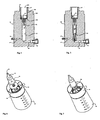
- the collar 25 is preferably cylindrical, and is configured to mate with the vacuum manifold 12 on annular shoulder 12A ( Figure 4 ).
- Collar 25 includes an inner annular ring 26, preferably centrally located in the collar 25, which attaches to the protruding member 27 of the manifold 12. Any suitable means of attachment can be used, such as threads. Preferably the attachment is not permanent, so that the manifold 12 can be reused with other sample holders and collars.
- the collar also includes an adaptor 33, best seen in Figures 2 and 3 .
- the adaptor 33 is preferably cylindrical and centrally located in the collar 25, preferably circumscribed by inner annular ring 26. It includes a sealing element 34 such as an O-ring, for sealing about filtration device 30. Alternatively, a gasket 36 ( Figure 6 ) can be used for sealing, which provides a face seal with the open end of the filter unit.
- the sample holder 20 and collar 25 combination is commercially available from Millipore Corporation and is sold under the StericupTM or SteritopTM name.
- the filtration device 30 is preferably a one-piece housing made from a plastic material such as a polyolefin, particularly polypropylene. It is generally cylindrical, with an upper portion 38 defining a sample chamber, larger enough to contain the required elution volume,that converges to a smaller, generally cylindrical lower portion that contains the chromatography media. The lower portion 39 terminates in a spout 40 defining a fluid outlet for the device.
- the device 30 preferably includes chromatography media 45 ( Figures 4, and 5 ), the formats of which are not particularly limited. Basically, any media used in peptide and/or protein recovery can be used in this device.
- suitable media include functional composite structures comprising resin particles derivatized with functional groups including styrenedivinyl-benzene-based media (unmodified or derivatized with e.g., sulphonic acids, quaternary amines, etc.); silica-based media (unmodified or derivatized with C 2 , C 4 , C 6 , C 8 , or C 18 or ion exchange functionalities), to accommodate a variety of applications for peptides, proteins, nucleic acids, and other organic compounds.
- functional composite structures comprising resin particles derivatized with functional groups including styrenedivinyl-benzene-based media (unmodified or derivatized with e.g., sulphonic acids, quaternary amines, etc.); silica-based media (unmodified or derivatized with C 2 , C 4 , C 6 , C 8 , or C 18 or ion exchange functionalities), to accommodate a variety of applications for
- media formed of polysaccharides such as agarose, crosslinked agarose or dextran or of trisacyrl polymers can be used alone or can be used with various capture chemistries attached to them such as ligands including but limited to Protein A, Protein G, Protein G and the like. Further examples include paramagnetic particles that contain a capture chemistry. Likewise one can utilize controlled pore glass alone or with a ligand such as Protein A (including ProSep®A controlled pore glass media available from Millipore Corporation of Billerica, Massachusetts).
- matrices with alternative selectivities e.g., hydrophobic interaction media, ion exchange media, reverse phase media, affinity media (e.g., Protein A, Protein G, Protein L, boronate affinity resins), etc.
- affinity media e.g., Protein A, Protein G, Protein L, boronate affinity resins
- Stacked membranes are also suitable as chromatography media.
- Suitable devices may incorporate a plurality of composite porous structures having materials with different functional groups to fractionate analytes that vary by charge, size, affinity and/or hydrophobicity, and include stacked filters such as glass fiber disc, surface charged membranes or membrane with affinity molecules coupled to the membrane surface.
- particles as used herein is intended to encompass particles having regular (e.g., spherical) or irregular shapes, as well as shards, fibers and powders and optionally including capture chemistries as mentioned above. These particles may be contained between glass, metal or plastic frit or glass mats or plastic non-wovens as is well known in chromatography packing. Alternatively, they may be packed into a chromatography packet that can then be inserted into the device.
- the filtration device 30 is configured to be slidably received in the bore 15 of the manifold 12.
- the top rim 37 of the filtration device may include an annular flange that sits on the top shoulder of the manifold 12, as seen in Figures 4 and 5 .
- a sealing means 46 positioned on shoulder 15B of the manifold 12.
- Suitable sealing means include an o-ring, flat elastomeric gaskets, or the like, to couple the filtration device 30 and the manifold 12 to create a flow path for the sample.
- a suitable centrifugal filter unit 60 such as an Amicon® Ultra unit containing an Ultracel® membrane, commercially available from Millipore Corporation, can be used.
- the centrifuge device is placed below the filter unit after the binding and the washing steps are complete. It is positioned to collection the eluant that may be further concentrated prior to analysis or use.
- the flow rate of sample through the device can be controlled in a number of ways.
- an air leak can be introduced, such as via vent 14 to reduce the vacuum pressure applied to the filter device 30 thereby slowing the flow rate through the device.
- the packing of the chromatographic media in the filtration device 30, and/or the filter in the sample holder 20, can be modified to control flow.
- the device is assembled with a filtration device 30 positioned in the manifold and the sample holder 20 and collar 25 sealingly positioned over the manifold.
- Sample is added to the sample holder, and vacuum is applied to the device.
- the sample flows into the filtration device 30 (preferably after passing through the pre-filter in the sample holder 20), and molecules of interest bind to the media in the filtration device. Molecules that are not of interest pass through the device and are directed to waste or a collection vessel.
- the bound molecules optionally can then be washed by introducing a suitable wash solution into the sample holder 20, again with the application of vacuum.
- the filtration device can be removed from the manifold and subjected to further processing, such as centrifugation to elute the molecules of interest.
- a centrifugal device 60 ( Figure 5 ), such as an ultrafiltration centrifugual device, is positioned in the manifold downstream of the filtration device such as after the bind and wash steps and prior to the elution step. Fluid flowing out of the filtration device is received by the centrifugal device for further processing and analysis.
- Figures 8-13 illustrate another embodiment wherein the manifold 12' is a bottle or similar housing adapted to be used in communication with a source of vacuum.
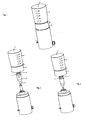
- the sample reservoir 20, (which includes a fitting 44 connectable to a vacuum source), and the filtration device 30, as well as the optional centrifugal device 60, are as described above and are shown in the assembled condition in Figure 12 .
- the manifold 12' includes a volume sufficient to contain the filtration device 30 and optional centrifugal device 60, as best seen in Figure 9 .
- the manifold 12' includes an upper lip 62 having external threads 63 for sealingly engaging corresponding inner threads in the inner annular ring 26 of the collar 25.
- the upper lip 62 has an outer diameter smaller that the outer diameter of the annular flange 81 of the filtration device 30, so that the annular flange 81 can seat on the top surface of the upper lip 62 as shown in Figure 9 .
- An adapter 33' seals the filtration device 30 to the sample holder 20 as shown.
- the centrifugal device 60 is not used, and filtrate from the filtration device 30 simply collects in the manifold 12'. Depending on the application, this filtrate may be used or discarded.
- Suitable materials for the manifold 12' include stainless steel, glass, plastics preferably polyolefins such as polyethylene and polypropylene, but most typically polystyrene.
- Figures 11 and 13 illustrate an embodiment wherein the eluant from the filtration device 30 is collected in a collection tube 70.
- the eluted sample so collected can be stored or further processed.
Landscapes
- Health & Medical Sciences (AREA)
- Chemical & Material Sciences (AREA)
- Analytical Chemistry (AREA)
- General Health & Medical Sciences (AREA)
- Hematology (AREA)
- Clinical Laboratory Science (AREA)
- Chemical Kinetics & Catalysis (AREA)
- Physics & Mathematics (AREA)
- Life Sciences & Earth Sciences (AREA)
- Biochemistry (AREA)
- General Physics & Mathematics (AREA)
- Immunology (AREA)
- Pathology (AREA)
- Sampling And Sample Adjustment (AREA)
- Separation Using Semi-Permeable Membranes (AREA)
- Devices For Use In Laboratory Experiments (AREA)
- Solid-Sorbent Or Filter-Aiding Compositions (AREA)
- Treatment Of Liquids With Adsorbents In General (AREA)
Claims (12)
- Eine Vorrichtung zur Vorbereitung von Proben, bestehend aus:• einem Probenreservoir (20), einem Vakuumverteiler (12) mit einer Bohrung und einer Filtereinheit (30), so dass ein Filtrierweg vom Probenreservoir durch besagte Filtereinheit zu besagtem Verteiler hergestellt wird, wobei sich die genannte Filtereinheit in der Bohrung des besagten Vakuumverteilers befindet, dadurch gekennzeichnet, dass besagte Filtereinheit eine Probenkammer (38) und eine untere Kammer beinhaltet, die ein kleineres Volumen als besagte Probenkammer (38) aufweist und Chromatographiemedien (45) enthält, wobei sich besagte Probenkammer (38) in Bezug auf die Fliessrichtung vor den genannten Chromatographiemedien befindet, besagte Probenkammer ein kleineres Volumen als besagtes Probenreservoir besitzt, und das genannte Reservoir und der Verteiler abdichtend miteinander in Eingriff stehen.
- Die Vorrichtung zur Vorbereitung von Proben nach Anspruch 1, wobei es sich bei der Filtereinheit um ein einteiliges Gehäuse aus einem Kunststoffmaterial handelt.
- Die Vorrichtung zur Vorbereitung von Proben nach Anspruch 1, wobei die Filtereinheit in der Bohrung des Verteilers gleitbar aufgenommen ist.
- Die Vorrichtung zur Vorbereitung von Proben nach Anspruch 1, wobei besagte Filtereinheit aus besagtem Verteiler entnommen werden kann.
- Die Vorrichtung zur Vorbereitung von Proben nach Anspruch 1, wobei besagtes Probenreservoir ein Volumen von mindestens 500 Milliliter aufweist.
- Die Vorrichtung zur Vorbereitung von Proben nach Anspruch 1, wobei sich besagte Filtereinheit in besagter Bohrung hinter dem genannten Probenreservoir befindet, und die Vorrichtung desweiteren eine Zentrifugalfiltereinheit (60) besitzt, die sich in besagter Bohrung hinter besagter Filtereinheit befindet, oder besagte Bohrung im genannten Verteiler so angepasst ist, dass sie mit der Vakuumquelle in Verbindung steht.
- Die Vorrichtung zur Vorbereitung von Proben nach Anspruch 1, wobei besagte Chromatographiemedien aus der Gruppe bestehend aus funktionellen Kompositstrukturen gewählt werden, die mit funktionellen Gruppen und Silica-basierten Medien derivatisierte Harzpartikel beinhalten, oder wobei besagte Chromatographiemedien aus der Gruppe bestehend aus funktionellen Kompositstrukturen gewählt werden, die eine oder mehrere Schichten von mit funktionellen Gruppen oder Silicabasierte Medien enthaltenden Kompositmembranstrukturen derivatisierte Membranen beinhalten.
- Die Vorrichtung zur Vorbereitung von Proben nach Anspruch 1, wobei besagtes Probenreservoir ein Filter (31) beinhaltet.
- Die Vorrichtung zur Vorbereitung von Proben nach Anspruch 1, die desweiteren eine Vakuumquelle beinhaltet, und wobei es sich bei besagtem Verteiler um ein Filtratsammelgefäß handelt, das mit besagter Vakuumquelle und besagter Filtereinheit in Verbindung steht.
- Ein Verfahren zum Reinigen einer Probe mit Hilfe der Vorrichtung zur Vorbereitung von Proben nach Anspruch 1, das folgendes beinhaltet:• Einführen besagter Probe in das genannte Probenreservoir,• Ziehen besagter Probe durch das genannte Probenreservoir in besagte Filtereinheit mit Hilfe von Vakuum aus einer Vakuumquelle, die mit besagtem Verteiler in Verbindung steht, um interessierende Moleküle an besagte Chromatographiemedien zu binden,• Entfernen besagter Filtereinheit aus besagtem Verteiler, und• Eluieren besagter interessierender Moleküle aus besagten Chromatographiemedien.
- Das Verfahren nach Anspruch 10, desweiteren beinhaltend die Weiterverarbeitung der interessierenden eluierten Moleküle durch Zentrifugieren.
- Das Verfahren nach Anspruch 10, desweiteren gekennzeichnet durch das• Einführen einer mit besagtem Verteiler in Fluidverbindung stehenden Zentrifugalfiltereinheit (60) hinter der genannten ersten Filtereinheit,• Eluieren der genannten interessierenden Moleküle aus besagten Chromatographiemedien in die genannte Zentrifugalfiltereinheit,• Entfernen der genannten Zentrifugalfiltereinheit von besagtem Verteiler, und• Zentrifugieren der genannten Zentrifugalfiltereinheit.
Applications Claiming Priority (2)
| Application Number | Priority Date | Filing Date | Title |
|---|---|---|---|
| US54567104P | 2004-02-18 | 2004-02-18 | |
| US545671P | 2004-02-18 |
Publications (2)
| Publication Number | Publication Date |
|---|---|
| EP1566209A1 EP1566209A1 (de) | 2005-08-24 |
| EP1566209B1 true EP1566209B1 (de) | 2013-06-19 |
Family
ID=34710271
Family Applications (1)
| Application Number | Title | Priority Date | Filing Date |
|---|---|---|---|
| EP05250884.3A Expired - Lifetime EP1566209B1 (de) | 2004-02-18 | 2005-02-16 | Verfahren und Vorrichtung für vakuumunterstützte Affinitätschromatographie |
Country Status (4)
| Country | Link |
|---|---|
| US (2) | US7240572B2 (de) |
| EP (1) | EP1566209B1 (de) |
| JP (1) | JP4020917B2 (de) |
| ES (1) | ES2418831T3 (de) |
Families Citing this family (25)
| Publication number | Priority date | Publication date | Assignee | Title |
|---|---|---|---|---|
| GB2427467A (en) * | 2004-11-13 | 2006-12-27 | Hossein Salar Amoli | Solid phase extraction apparatus |
| CN101312785B (zh) * | 2005-09-02 | 2011-03-30 | 罗什生命科学公司 | 用于真空过滤的系统、设备和方法 |
| WO2008144083A1 (en) * | 2007-05-23 | 2008-11-27 | Nypro Inc. | Methods and apparatus for foam control in a vacuum filtration system |
| WO2009014767A1 (en) * | 2007-07-26 | 2009-01-29 | Nypro Inc. | Vacuum base and related methods and apparatus for vacuum filtration |
| WO2009014768A1 (en) * | 2007-07-26 | 2009-01-29 | Nypro Inc. | Method and apparatus for filtrate storage handling |
| US8357296B2 (en) * | 2007-09-24 | 2013-01-22 | Emd Millipore Corporation | Centrifugal filter |
| KR101005924B1 (ko) * | 2008-06-27 | 2011-01-06 | 포항공과대학교 산학협력단 | 핵산 추출 장치 |
| WO2010101865A1 (en) * | 2009-03-02 | 2010-09-10 | Zymo Research Corporation | Universal column |
| DE102009052671B4 (de) | 2009-11-12 | 2015-07-30 | Sartorius Stedim Biotech Gmbh | Vorrichtung und Verfahren zur Behandlung eines Filtrationsmediums |
| DE102010011485A1 (de) | 2010-03-16 | 2011-09-22 | Sartorius Stedim Biotech Gmbh | Mehrfachlochplatte mit Filtermedium und ihre Verwendung |
| CN101943641B (zh) * | 2010-08-27 | 2013-07-03 | 华南理工大学 | 一种下位载样器 |
| US8808552B2 (en) * | 2010-12-16 | 2014-08-19 | Zenpure (Hangzhou) Co., Ltd. | Stackable filter cup apparatus and method |
| USD681816S1 (en) | 2010-12-23 | 2013-05-07 | Emd Millipore Corporation | Filter assembly |
| USD679812S1 (en) | 2010-12-23 | 2013-04-09 | Emd Millipore Corporation | Filter |
| US9157838B2 (en) | 2010-12-23 | 2015-10-13 | Emd Millipore Corporation | Chromatography apparatus and method |
| US9304070B2 (en) | 2011-07-13 | 2016-04-05 | Emd Millipore Corporation | All-in-one sample preparation device and method |
| CA2854768C (en) * | 2011-11-10 | 2021-08-17 | David E. Jones | Loading vials |
| CA2851112A1 (en) * | 2013-05-06 | 2014-11-06 | Tomas Hudlicky | Methods and apparatus for time-pulsed chromatography |
| EP3041594B1 (de) * | 2013-09-05 | 2022-02-23 | Merck Patent GmbH | Filtervorrichtung zum filtern komplexer flüssigkeitsproben |
| US10188967B2 (en) | 2013-12-04 | 2019-01-29 | Pocared Diagnostics Ltd. | Filter arrangement with slider valve and method for using the same |
| US10589198B2 (en) * | 2015-03-20 | 2020-03-17 | Marin Scientific Development Company | High flow, low hold up filters |
| US10549214B2 (en) * | 2017-03-10 | 2020-02-04 | Savannah River Nuclear Solutions, Llc | Device for residue handling minimization with vacuum-assisted separations |
| WO2019026026A1 (en) | 2017-08-02 | 2019-02-07 | Pocared Diagnostics Ltd. | PROCESSOR FILTER ARRANGEMENT COMPRISING A METHOD AND APPARATUS FOR REMOVING A RESIDUAL FLUID THROUGH A FILTER |
| CN109603244A (zh) * | 2019-01-08 | 2019-04-12 | 贵州大学 | 一种用于组培过滤的夹持装置 |
| WO2021042070A1 (en) * | 2019-08-30 | 2021-03-04 | Protifi, Llc | Detergent-free simultaneous multiomics sample preparation method using novel new vesicle design |
Family Cites Families (30)
| Publication number | Priority date | Publication date | Assignee | Title |
|---|---|---|---|---|
| US3063286A (en) * | 1959-07-14 | 1962-11-13 | Standard Oil Co | Sample introduction system for gas chromatography apparatus |
| US3630683A (en) * | 1969-02-14 | 1971-12-28 | Telan Corp | Reactor device for ion exchange resins and the like |
| US3731466A (en) * | 1971-07-14 | 1973-05-08 | Us Agriculture | Continuous flow multiple trap for low temperature reduced pressure gas chromatography |
| US3953172A (en) * | 1974-05-10 | 1976-04-27 | Union Carbide Corporation | Method and apparatus for assaying liquid materials |
| US4427415A (en) * | 1979-01-05 | 1984-01-24 | Cleveland Patrick H | Manifold vacuum biochemical test method and device |
| US4213326A (en) * | 1979-02-14 | 1980-07-22 | The Upjohn Company | Sample supply device |
| US4422941A (en) * | 1980-09-08 | 1983-12-27 | University Of Pittsburgh | Apparatus for liquid-solid column centrifugation chromatography and method |
| US4755301A (en) | 1983-08-15 | 1988-07-05 | W. R. Grace & Co. | Apparatus and method for centrifugal recovery of retentate |
| US4871662A (en) * | 1986-08-11 | 1989-10-03 | Watertest Corporation | Device for shipping microbiology test samples |
| US5099743A (en) * | 1987-07-08 | 1992-03-31 | Thermedics Inc. | Selective detection with high speed gas chromatography |
| CA2006880A1 (en) * | 1989-01-03 | 1990-07-03 | William D. Huse | Push column and chromatography method |
| US5264184A (en) * | 1991-03-19 | 1993-11-23 | Minnesota Mining And Manufacturing Company | Device and a method for separating liquid samples |
| US5238556A (en) * | 1992-05-13 | 1993-08-24 | Hamid Shirkhan | Chromatography tube for use within a pressurized circuit |
| US5375477A (en) * | 1993-01-04 | 1994-12-27 | S.P. Industries, Limited Partnership | Water impurity extraction device and method |
| US5730943A (en) * | 1993-08-12 | 1998-03-24 | Optimize Technologies, Inc. | Integral fitting and filter of an analytical chemical instrument |
| US5976824A (en) * | 1993-11-24 | 1999-11-02 | Abbott Laboratories | Method and apparatus for collecting a cell sample from a liquid specimen |
| WO1995027546A1 (en) * | 1994-04-08 | 1995-10-19 | Amicon, Inc. | Method and apparatus for isolation and purification of biologically active complexes |
| US5601711A (en) * | 1994-10-31 | 1997-02-11 | Gelman Sciences Inc. | Selective separation filter device |
| US5603899A (en) * | 1995-04-12 | 1997-02-18 | Pharmacia Biotech, Inc. | Multiple column chromatography assembly |
| US5667754A (en) * | 1995-09-25 | 1997-09-16 | Hach Company | Device for chloride ion removal prior to chemical oxygen demand analysis |
| WO1999000168A1 (en) * | 1997-06-27 | 1999-01-07 | Life Technologies, Inc. | One step device and process for concentration and purification of biological molecules |
| US6156196A (en) * | 1997-12-22 | 2000-12-05 | Zhiling Gao | Apparatus for visible, preparative column chromatography |
| US20020102563A1 (en) * | 1998-04-24 | 2002-08-01 | Gjerde Douglas T. | Apparatus and method for separating and purifying polynucleotides |
| DE19937187A1 (de) | 1999-08-06 | 2001-03-01 | Qiagen Gmbh | Automatisierte Proteinreinigung im Multiwellformat durch Vakuumfiltration |
| WO2002016580A2 (en) | 2000-08-24 | 2002-02-28 | Bio-Rad Laboratories, Inc. | Flow-through system for lysate clarification and nucleic acid binding in a single step |
| JP2004517310A (ja) * | 2001-01-05 | 2004-06-10 | プロ・ケム インク | 精製器具及び方法 |
| US7066011B2 (en) * | 2001-06-07 | 2006-06-27 | Nano Solution, Inc. | Liquid chromatograph and analysis system |
| US7749388B2 (en) * | 2001-06-15 | 2010-07-06 | Life Technologies Corporation | Low volume filtration column devices and methods of filtering therewith |
| US20050115903A1 (en) * | 2002-04-09 | 2005-06-02 | Genesystems | Method and apparatus for extracting nucleic acids from a complex mixture |
| US6824678B2 (en) * | 2003-02-06 | 2004-11-30 | Robert D. Thompson | Closure system for chromatography columns |
-
2005
- 2005-02-04 US US11/051,047 patent/US7240572B2/en not_active Expired - Lifetime
- 2005-02-16 EP EP05250884.3A patent/EP1566209B1/de not_active Expired - Lifetime
- 2005-02-16 ES ES05250884T patent/ES2418831T3/es not_active Expired - Lifetime
- 2005-02-18 JP JP2005042171A patent/JP4020917B2/ja not_active Expired - Lifetime
-
2007
- 2007-01-26 US US11/698,663 patent/US7546779B2/en not_active Expired - Lifetime
Also Published As
| Publication number | Publication date |
|---|---|
| US7546779B2 (en) | 2009-06-16 |
| US20070227975A1 (en) | 2007-10-04 |
| JP2005241640A (ja) | 2005-09-08 |
| US20050178216A1 (en) | 2005-08-18 |
| ES2418831T3 (es) | 2013-08-16 |
| EP1566209A1 (de) | 2005-08-24 |
| US7240572B2 (en) | 2007-07-10 |
| JP4020917B2 (ja) | 2007-12-12 |
Similar Documents
| Publication | Publication Date | Title |
|---|---|---|
| US7546779B2 (en) | Vacuum assisted affinity chromatography device and method | |
| JP5544399B2 (ja) | オールインワン型のサンプル調製装置及び方法 | |
| KR102178191B1 (ko) | 크로마토그래피 막, 이를 포함하는 장치 및 이의 이용방법 | |
| US8574923B2 (en) | Sample preparation device | |
| EP2217344B1 (de) | Verfahren zur Reinigung einer Nukleinsäure einer Probe | |
| EP1577319B1 (de) | Proteinaufreinigung mit vorfiltration | |
| US20020110495A1 (en) | Devices and methods for purification | |
| WO2000048703B1 (en) | Purification of biological substances | |
| EP0651675A1 (de) | Verfahren zur Zentrifugalkonzentrierung von Makromolekülen und Vorrichtung zur Durchführung des Verfahrens. | |
| US10792618B2 (en) | Particle separation and/or purification of a fluid | |
| WO2001034268A1 (en) | Methods and apparatus for capturing target substances from liquid media | |
| WO2004047948A1 (en) | Chromatographic separation processes and apparatus | |
| GB2332157A (en) | Fabric reinforced adsorptive membrane | |
| WO2024079611A1 (en) | Vacuum driven gel filtration method |
Legal Events
| Date | Code | Title | Description |
|---|---|---|---|
| PUAI | Public reference made under article 153(3) epc to a published international application that has entered the european phase |
Free format text: ORIGINAL CODE: 0009012 |
|
| AK | Designated contracting states |
Kind code of ref document: A1 Designated state(s): AT BE BG CH CY CZ DE DK EE ES FI FR GB GR HU IE IS IT LI LT LU MC NL PL PT RO SE SI SK TR |
|
| AX | Request for extension of the european patent |
Extension state: AL BA HR LV MK YU |
|
| 17P | Request for examination filed |
Effective date: 20051109 |
|
| AKX | Designation fees paid |
Designated state(s): DE ES FR GB IT |
|
| 17Q | First examination report despatched |
Effective date: 20081028 |
|
| RAP1 | Party data changed (applicant data changed or rights of an application transferred) |
Owner name: EMD MILLIPORE CORPORATION |
|
| REG | Reference to a national code |
Ref country code: DE Ref legal event code: R079 Ref document number: 602005040022 Country of ref document: DE Free format text: PREVIOUS MAIN CLASS: B01D0015080000 Ipc: G01N0001400000 |
|
| GRAP | Despatch of communication of intention to grant a patent |
Free format text: ORIGINAL CODE: EPIDOSNIGR1 |
|
| RIC1 | Information provided on ipc code assigned before grant |
Ipc: G01N 1/40 20060101AFI20130109BHEP |
|
| GRAS | Grant fee paid |
Free format text: ORIGINAL CODE: EPIDOSNIGR3 |
|
| GRAA | (expected) grant |
Free format text: ORIGINAL CODE: 0009210 |
|
| AK | Designated contracting states |
Kind code of ref document: B1 Designated state(s): DE ES FR GB IT |
|
| REG | Reference to a national code |
Ref country code: GB Ref legal event code: FG4D |
|
| REG | Reference to a national code |
Ref country code: DE Ref legal event code: R096 Ref document number: 602005040022 Country of ref document: DE Effective date: 20130814 |
|
| REG | Reference to a national code |
Ref country code: ES Ref legal event code: FG2A Ref document number: 2418831 Country of ref document: ES Kind code of ref document: T3 Effective date: 20130816 |
|
| PG25 | Lapsed in a contracting state [announced via postgrant information from national office to epo] |
Ref country code: IT Free format text: LAPSE BECAUSE OF NON-PAYMENT OF DUE FEES Effective date: 20130216 |
|
| PLBE | No opposition filed within time limit |
Free format text: ORIGINAL CODE: 0009261 |
|
| STAA | Information on the status of an ep patent application or granted ep patent |
Free format text: STATUS: NO OPPOSITION FILED WITHIN TIME LIMIT |
|
| 26N | No opposition filed |
Effective date: 20140320 |
|
| REG | Reference to a national code |
Ref country code: DE Ref legal event code: R097 Ref document number: 602005040022 Country of ref document: DE Effective date: 20140320 |
|
| REG | Reference to a national code |
Ref country code: FR Ref legal event code: PLFP Year of fee payment: 12 |
|
| REG | Reference to a national code |
Ref country code: FR Ref legal event code: PLFP Year of fee payment: 13 |
|
| REG | Reference to a national code |
Ref country code: FR Ref legal event code: PLFP Year of fee payment: 14 |
|
| PGFP | Annual fee paid to national office [announced via postgrant information from national office to epo] |
Ref country code: FR Payment date: 20231212 Year of fee payment: 20 |
|
| PGFP | Annual fee paid to national office [announced via postgrant information from national office to epo] |
Ref country code: ES Payment date: 20240304 Year of fee payment: 20 |
|
| PGFP | Annual fee paid to national office [announced via postgrant information from national office to epo] |
Ref country code: DE Payment date: 20231220 Year of fee payment: 20 Ref country code: GB Payment date: 20240108 Year of fee payment: 20 |
|
| PGFP | Annual fee paid to national office [announced via postgrant information from national office to epo] |
Ref country code: IT Payment date: 20240111 Year of fee payment: 20 |
|
| REG | Reference to a national code |
Ref country code: DE Ref legal event code: R071 Ref document number: 602005040022 Country of ref document: DE |
|
| REG | Reference to a national code |
Ref country code: ES Ref legal event code: FD2A Effective date: 20250228 |
|
| REG | Reference to a national code |
Ref country code: GB Ref legal event code: PE20 Expiry date: 20250215 |
|
| PG25 | Lapsed in a contracting state [announced via postgrant information from national office to epo] |
Ref country code: ES Free format text: LAPSE BECAUSE OF EXPIRATION OF PROTECTION Effective date: 20250217 |
|
| PG25 | Lapsed in a contracting state [announced via postgrant information from national office to epo] |
Ref country code: GB Free format text: LAPSE BECAUSE OF EXPIRATION OF PROTECTION Effective date: 20250215 |