EP1565903B1 - Elektrophoretische anzeigetafel - Google Patents
Elektrophoretische anzeigetafel Download PDFInfo
- Publication number
- EP1565903B1 EP1565903B1 EP03758534A EP03758534A EP1565903B1 EP 1565903 B1 EP1565903 B1 EP 1565903B1 EP 03758534 A EP03758534 A EP 03758534A EP 03758534 A EP03758534 A EP 03758534A EP 1565903 B1 EP1565903 B1 EP 1565903B1
- Authority
- EP
- European Patent Office
- Prior art keywords
- picture
- duration
- potential difference
- drive means
- display panel
- Prior art date
- Legal status (The legal status is an assumption and is not a legal conclusion. Google has not performed a legal analysis and makes no representation as to the accuracy of the status listed.)
- Expired - Lifetime
Links
Images

Classifications
-
- G—PHYSICS
- G09—EDUCATION; CRYPTOGRAPHY; DISPLAY; ADVERTISING; SEALS
- G09G—ARRANGEMENTS OR CIRCUITS FOR CONTROL OF INDICATING DEVICES USING STATIC MEANS TO PRESENT VARIABLE INFORMATION
- G09G3/00—Control arrangements or circuits, of interest only in connection with visual indicators other than cathode-ray tubes
- G09G3/20—Control arrangements or circuits, of interest only in connection with visual indicators other than cathode-ray tubes for presentation of an assembly of a number of characters, e.g. a page, by composing the assembly by combination of individual elements arranged in a matrix no fixed position being assigned to or needed to be assigned to the individual characters or partial characters
- G09G3/34—Control arrangements or circuits, of interest only in connection with visual indicators other than cathode-ray tubes for presentation of an assembly of a number of characters, e.g. a page, by composing the assembly by combination of individual elements arranged in a matrix no fixed position being assigned to or needed to be assigned to the individual characters or partial characters by control of light from an independent source
- G09G3/3433—Control arrangements or circuits, of interest only in connection with visual indicators other than cathode-ray tubes for presentation of an assembly of a number of characters, e.g. a page, by composing the assembly by combination of individual elements arranged in a matrix no fixed position being assigned to or needed to be assigned to the individual characters or partial characters by control of light from an independent source using light modulating elements actuated by an electric field and being other than liquid crystal devices and electrochromic devices
- G09G3/344—Control arrangements or circuits, of interest only in connection with visual indicators other than cathode-ray tubes for presentation of an assembly of a number of characters, e.g. a page, by composing the assembly by combination of individual elements arranged in a matrix no fixed position being assigned to or needed to be assigned to the individual characters or partial characters by control of light from an independent source using light modulating elements actuated by an electric field and being other than liquid crystal devices and electrochromic devices based on particles moving in a fluid or in a gas, e.g. electrophoretic devices
-
- G—PHYSICS
- G02—OPTICS
- G02F—OPTICAL DEVICES OR ARRANGEMENTS FOR THE CONTROL OF LIGHT BY MODIFICATION OF THE OPTICAL PROPERTIES OF THE MEDIA OF THE ELEMENTS INVOLVED THEREIN; NON-LINEAR OPTICS; FREQUENCY-CHANGING OF LIGHT; OPTICAL LOGIC ELEMENTS; OPTICAL ANALOGUE/DIGITAL CONVERTERS
- G02F1/00—Devices or arrangements for the control of the intensity, colour, phase, polarisation or direction of light arriving from an independent light source, e.g. switching, gating or modulating; Non-linear optics
- G02F1/01—Devices or arrangements for the control of the intensity, colour, phase, polarisation or direction of light arriving from an independent light source, e.g. switching, gating or modulating; Non-linear optics for the control of the intensity, phase, polarisation or colour
- G02F1/165—Devices or arrangements for the control of the intensity, colour, phase, polarisation or direction of light arriving from an independent light source, e.g. switching, gating or modulating; Non-linear optics for the control of the intensity, phase, polarisation or colour based on translational movement of particles in a fluid under the influence of an applied field
- G02F1/166—Devices or arrangements for the control of the intensity, colour, phase, polarisation or direction of light arriving from an independent light source, e.g. switching, gating or modulating; Non-linear optics for the control of the intensity, phase, polarisation or colour based on translational movement of particles in a fluid under the influence of an applied field characterised by the electro-optical or magneto-optical effect
- G02F1/167—Devices or arrangements for the control of the intensity, colour, phase, polarisation or direction of light arriving from an independent light source, e.g. switching, gating or modulating; Non-linear optics for the control of the intensity, phase, polarisation or colour based on translational movement of particles in a fluid under the influence of an applied field characterised by the electro-optical or magneto-optical effect by electrophoresis
-
- G—PHYSICS
- G02—OPTICS
- G02F—OPTICAL DEVICES OR ARRANGEMENTS FOR THE CONTROL OF LIGHT BY MODIFICATION OF THE OPTICAL PROPERTIES OF THE MEDIA OF THE ELEMENTS INVOLVED THEREIN; NON-LINEAR OPTICS; FREQUENCY-CHANGING OF LIGHT; OPTICAL LOGIC ELEMENTS; OPTICAL ANALOGUE/DIGITAL CONVERTERS
- G02F1/00—Devices or arrangements for the control of the intensity, colour, phase, polarisation or direction of light arriving from an independent light source, e.g. switching, gating or modulating; Non-linear optics
- G02F1/01—Devices or arrangements for the control of the intensity, colour, phase, polarisation or direction of light arriving from an independent light source, e.g. switching, gating or modulating; Non-linear optics for the control of the intensity, phase, polarisation or colour
- G02F1/165—Devices or arrangements for the control of the intensity, colour, phase, polarisation or direction of light arriving from an independent light source, e.g. switching, gating or modulating; Non-linear optics for the control of the intensity, phase, polarisation or colour based on translational movement of particles in a fluid under the influence of an applied field
- G02F1/1685—Operation of cells; Circuit arrangements affecting the entire cell
-
- G—PHYSICS
- G09—EDUCATION; CRYPTOGRAPHY; DISPLAY; ADVERTISING; SEALS
- G09G—ARRANGEMENTS OR CIRCUITS FOR CONTROL OF INDICATING DEVICES USING STATIC MEANS TO PRESENT VARIABLE INFORMATION
- G09G2310/00—Command of the display device
- G09G2310/02—Addressing, scanning or driving the display screen or processing steps related thereto
- G09G2310/0243—Details of the generation of driving signals
- G09G2310/0251—Precharge or discharge of pixel before applying new pixel voltage
-
- G—PHYSICS
- G09—EDUCATION; CRYPTOGRAPHY; DISPLAY; ADVERTISING; SEALS
- G09G—ARRANGEMENTS OR CIRCUITS FOR CONTROL OF INDICATING DEVICES USING STATIC MEANS TO PRESENT VARIABLE INFORMATION
- G09G2310/00—Command of the display device
- G09G2310/06—Details of flat display driving waveforms
-
- G—PHYSICS
- G09—EDUCATION; CRYPTOGRAPHY; DISPLAY; ADVERTISING; SEALS
- G09G—ARRANGEMENTS OR CIRCUITS FOR CONTROL OF INDICATING DEVICES USING STATIC MEANS TO PRESENT VARIABLE INFORMATION
- G09G2310/00—Command of the display device
- G09G2310/06—Details of flat display driving waveforms
- G09G2310/066—Waveforms comprising a gently increasing or decreasing portion, e.g. ramp
-
- G—PHYSICS
- G09—EDUCATION; CRYPTOGRAPHY; DISPLAY; ADVERTISING; SEALS
- G09G—ARRANGEMENTS OR CIRCUITS FOR CONTROL OF INDICATING DEVICES USING STATIC MEANS TO PRESENT VARIABLE INFORMATION
- G09G2310/00—Command of the display device
- G09G2310/06—Details of flat display driving waveforms
- G09G2310/068—Application of pulses of alternating polarity prior to the drive pulse in electrophoretic displays
-
- G—PHYSICS
- G09—EDUCATION; CRYPTOGRAPHY; DISPLAY; ADVERTISING; SEALS
- G09G—ARRANGEMENTS OR CIRCUITS FOR CONTROL OF INDICATING DEVICES USING STATIC MEANS TO PRESENT VARIABLE INFORMATION
- G09G2320/00—Control of display operating conditions
- G09G2320/02—Improving the quality of display appearance
- G09G2320/0247—Flicker reduction other than flicker reduction circuits used for single beam cathode-ray tubes
-
- G—PHYSICS
- G09—EDUCATION; CRYPTOGRAPHY; DISPLAY; ADVERTISING; SEALS
- G09G—ARRANGEMENTS OR CIRCUITS FOR CONTROL OF INDICATING DEVICES USING STATIC MEANS TO PRESENT VARIABLE INFORMATION
- G09G2320/00—Control of display operating conditions
- G09G2320/02—Improving the quality of display appearance
- G09G2320/0252—Improving the response speed
-
- G—PHYSICS
- G09—EDUCATION; CRYPTOGRAPHY; DISPLAY; ADVERTISING; SEALS
- G09G—ARRANGEMENTS OR CIRCUITS FOR CONTROL OF INDICATING DEVICES USING STATIC MEANS TO PRESENT VARIABLE INFORMATION
- G09G3/00—Control arrangements or circuits, of interest only in connection with visual indicators other than cathode-ray tubes
- G09G3/20—Control arrangements or circuits, of interest only in connection with visual indicators other than cathode-ray tubes for presentation of an assembly of a number of characters, e.g. a page, by composing the assembly by combination of individual elements arranged in a matrix no fixed position being assigned to or needed to be assigned to the individual characters or partial characters
- G09G3/2007—Display of intermediate tones
- G09G3/2014—Display of intermediate tones by modulation of the duration of a single pulse during which the logic level remains constant
Definitions
- the invention relates to an electrophoretic display panel, for displaying a picture, comprising:
- the picture elements have, during the display of the picture, appearances determined by the positions of the charged particles between the electrodes.
- the positions of the particles depend, however, not only on the potential differences, but also on the history of the potential differences.
- the picture being displayed based on image information differs significantly from a picture being an exact representation of the image information. Therefore, the picture being displayed has a relatively low picture quality.
- the dependency on the history is reduced in the described electrophoretic display panel by the application of the preset potential differences for a predetermined duration before the application of the picture potential differences of picture elements having the largest duration of those differences.
- the picture quality could be increased by increasing the durations of the preset potential differences.
- the interval intended to be available for controlling both the preset potential differences and the picture potential differences is in general constant and in the range between 100 ms and 200 ms
- the interval available for the preset potential differences and the picture potential differences is a rather short and the dependency of the appearances of the picture elements on the history is still non-negligible. As a result, the picture being displayed still has a rather poor picture quality.
- the drive means are further arranged for controlling for each picture element of at least a number of the picture elements having smaller durations of the picture potential differences than the largest duration, the preset potential difference to have an additional duration, which is chosen in a range from larger than zero to equal to a difference between the largest duration and the actual duration of the picture potential difference.
- the durations of the picture potential differences vary between a smallest duration and a largest duration of the picture potential differences.
- a subset of the picture elements is formed by at least a number of the picture elements having smaller durations of the picture potential differences than the largest duration. The subset contains one picture element at the least and the total number of picture elements at the most.
- the preset potential difference has an additional duration
- the additional duration is positive and smaller than or equal to the difference between the largest duration of the picture potential differences and the actual duration.
- the object could also be achieved by the application of relatively large potential differences compared to potential differences of 15 Volts, because relatively large potential differences applied for relatively small durations have the same effect on the appearances as relatively small potential differences applied for relatively large durations.
- the display panel according to the present invention has the advantage that the object is achieved without the need of such relatively large potential differences. Therefore, standard driving electronics may be used.
- the drive means are further arranged for controlling the respective additional duration to be a decreasing function of the respective actual duration of the picture potential difference. Then, for each picture element of the subset, a smaller duration of the picture potential difference implies a larger additional duration of the preset potential difference. As a result, for each picture element of the subset the dependency of the appearance on the history is decreased and the picture quality is further improved.
- the drive means are further arranged for controlling the respective additional duration to be substantially equal to the difference between the largest duration of the picture potential differences and the respective actual duration of the picture potential difference. Then, for each picture element of the subset the additional duration of the preset potential difference is substantially equal to the largest duration available, resulting in a still further improved picture quality.
- the drive means are further arranged for controlling the preset values in the sequence to be subsequently of opposite value. Then the DC component and the visibility of the preset potential differences of the display panel are relatively small. If, furthermore, the drive means are further arranged for generating an even number of preset values, the DC component and the visibility of the preset potential differences of the display panel are further decreased.
- the picture elements are interconnected in two or more groups whereby preset potential differences having a different polarity are supplied to different groups. Then the perceptual appearance will hardly be effected, as the eye integrates the short brightness fluctuations.
- the first electrode comprises a data electrode and the second electrode comprises a selection electrode and the drive means further comprise first sub drive means for applying a selection potential to the selection electrode and second sub drive means for applying a data potential to the data electrode. Then the electrodes are arranged to form a passive matrix display.
- first electrode of each picture element is being coupled to a data electrode via a switching element, the switching element being controlled by a selection electrode, and the drive means further comprise first sub drive means for applying selection potentials to the selection electrodes and second sub drive means for applying data potentials to the data electrodes. Then the display panel is provided with an active matrix addressing to provide the data potentials to the electrodes of the picture elements.
- the selection electrodes associated with picture elements are interconnected in two groups, and the drive means are further arranged for generating a first preset potential difference having a first polarity to the first group and a second preset potential difference having a second polarity opposite to the first polarity to the second group. Then the picture elements are interconnected in two or more groups whereby preset potential differences having a different polarity are supplied to the different parts of the screen.
- each picture element having a duration of the actual picture potential difference smaller than the largest duration of the picture potential differences is one of the number of the picture elements. Then, for each of those picture elements, the dependency of the appearance on the history is decreased.
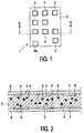
- Figures 1 and 2 show the embodiment of the display panel 1 having a first substrate 8, a second opposed substrate 9 and a plurality of picture elements 2.
- the picture elements 2 are arranged along substantially straight lines in a two-dimensional structure. Other arrangements of the picture elements 2 are alternatively possible, e.g. a honeycomb arrangement.
- An electrophoretic medium 5, having charged particles 6, is present between the substrates 8,9.
- a first and a second electrode 3,4 are associated with each picture element 2.
- the electrodes 3,4 are able to receive a potential difference.
- the first substrate 8 has for each picture element 2 a first electrode 3
- the second substrate 9 has for each picture element 2 a second electrode 4.
- the charged particles 6 are able to occupy extreme positions near the electrodes 3,4 and intermediate positions in between the electrodes 3,4.
- Each picture element 2 has an appearance determined by the position of the charged particles 6 between the electrodes 3,4.
- Electrophoretic media 5 are known per se from e.g. US 5,961,804, US 6,120,839 and US 6,130,774 and can e.g. be obtained from E Ink Corporation.
- the electrophoretic medium 5 comprises negatively charged black particles 6 in a white fluid.
- the appearance of the picture element 2 is e.g. white.
- the charged particles 6 are in the second extreme position, i.e. near the second electrode 4, due to a potential difference of opposite polarity, i.e.
- the drive means 100 are arranged for controlling the potential difference of each picture element 2 to be a preset potential difference.
- the preset potential difference has a sequence of preset values and a predetermined duration. The preset values in the sequence alternate in sign.
- the drive means 100 are further arranged for controlling each preset value for a sub-duration to represent an energy sufficient to release particles 6 present in one of said extreme positions from their position but insufficient to enable particles 6 to reach the other one of the extreme positions.
- the drive means 100 are further arranged for controlling the potential difference of each picture element 2 to be picture potential difference for displaying the picture by bringing the particles 6 into one of said positions, subsequent to be a preset potential difference.
- the picture potential difference has a value and an actual duration in the range between a smallest duration and a largest duration of the picture potential differences.
- the drive means 100 are arranged for controlling for each picture element 2 of at least a number of the picture elements 2 having smaller durations of the picture potential differences than the largest duration, the preset potential difference to have an additional duration, which is chosen in a range from larger than zero to equal to a difference between the largest duration and the actual duration of the picture potential difference.
- the potential difference of a picture element 2 for which the picture potential difference has the largest duration of the picture potential differences is shown as function of time in Figure 3A.
- the preset potential difference is present from time t1 to time t2 and has a predetermined duration of e.g. 40 ms and has e.g. 2 preset values, each preset values being applied for a sub-duration of 20 ms, the first being 15 Volts, the second being -15 Volts.
- the picture potential difference is present between time t2 and time t5 and has a value of 15 Volts and an actual duration of e.g. 160 ms.
- the actual duration of the picture potential difference is equal to the largest duration of the picture potential differences.
- the picture element 2 has an appearance being white, for displaying the picture.
- the potential difference is shown as a function of time for a particular picture element 2 of the number of the picture elements 2 having smaller durations of the picture potential differences than the largest duration.
- the actual duration of the picture potential difference is e.g. 100 ms, which is smaller than the largest duration of the picture potential differences of 160 ms as given in Figure 3A.
- the preset potential difference has an additional duration, from time t2 to time t3, of e.g. 40 ms.
- the preset values being 15 Volts or -15 Volts, in the sequence are subsequently of opposite value and, furthermore, the number of preset values, being 4, is even.
- the potential difference is shown as a function of time for an other picture element 2 of the number of the picture elements 2 having smaller durations of the picture potential differences than the largest duration.
- the actual duration of the picture potential differences is e.g. 40 ms.
- the preset potential difference has an additional duration, from time t2 to time t3, where t3 is substantially equal to t4, of e.g. 120 ms.
- the drive means 100 are further arranged for controlling the respective additional duration to be a decreasing function of the respective actual duration of the picture potential difference.
- the potential differences of the picture elements 2 referred to in Figure 3B and 3C have additional durations which are an example of such a decreasing function.
- Figure 4 shows three other examples of such decreasing functions.
- the largest duration of the picture potential differences is 160 ms as given in Figure 3A.
- the function represented by the line with label 'a' has a largest additional duration of the preset potential difference of 80 ms for an actual duration of the picture potential difference being zero.
- the function represented by the line with label 'b' has a largest additional duration of the preset potential difference of 100 ms for an actual duration of the picture potential difference being zero.
- the function represented by the straight line with label 'c' has a largest additional duration of the preset potential difference of 160 ms for an actual duration of the picture potential difference being zero.
- This function corresponds to a further variation of the embodiment where the drive means 100 are further arranged for controlling the respective additional duration to be substantially equal to the difference between the largest duration of the picture potential differences and the respective actual duration of the picture potential difference.
- the potential difference shown in Figure 3C represents an example of this embodiment.
- the potential differences are chosen from three values, -15 Volts, 0 and 15 Volts.
- the values of the potential differences are not restricted to these values as other potential difference values may be applied, even different values may be applied for the preset potential differences and the picture potential differences.
Claims (10)
- Elektrophoretische Anzeigetafel (1) zum Anzeigen eines Bildes, die Folgendes umfasst:- ein elektrophoretisches Medium (5), das geladene Partikel (6) umfasst,- mehrere Bildpunkte (2),- zugehörig zu jedem Bildpunkt (2) eine erste und eine zweite Elektrode (3,4) zum Aufnehmen einer Potentialdifferenz und- Ansteuermittel,wobei die geladenen Partikel (6) Extrempositionen bei den Elektroden (3,4) und Zwischenpositionen zwischen den Elektroden (3,4) einnehmen können,
wobei die Ansteuermittel dazu ausgelegt sind, die Potentialdifferenz jedes Bildpunkts (2)- auf eine Vorwahlpotentialdifferenz zu regeln, die eine Folge von Vorwahlwerten mit abwechselndem Vorzeichen und eine festgelegte Dauer aufweist, wobei jeder Vorwahlwert eine Sub-Dauer aufweist, die eine Energie darstellt, die ausreicht, um Partikel (6), die an einer der Extrempositionen vorhanden sind, aus ihrer Position zu lösen, aber nicht ausreicht, um Teilchen (6) an die jeweils andere Extremposition gelangen zu lassen, und die Potentialdifferenz anschließend- auf eine Bildpotentialdifferenz zu regeln, die einen Wert und eine tatsächliche Dauer im Bereich zwischen einer kürzesten Dauer und einer längsten Dauer aufweist, um das Bild anzuzeigen, indem die Partikel (6) in eine der Positionen gebracht werden,dadurch gekennzeichnet, dass
die Ansteuermittel ferner dazu ausgelegt sind, für jeden Bildpunkt aus einer Anzahl von Bildpunkten (2), deren Bildpotentialdifferenzen Dauern aufweisen, die kürzer als die längste Dauer sind, die Vorwahlpotentialdifferenz dergestalt zu regeln, dass sie eine zusätzliche Dauer aufweist, die aus einem Bereich ausgewählt wird, der von einer Dauer größer als null bis zu der Differenz zwischen der längsten Dauer und der tatsächlichen Dauer der Bildpotentialdifferenz reicht. - Anzeigetafel (1) nach Anspruch 1, dadurch gekennzeichnet, dass die Ansteuermittel ferner dazu ausgelegt sind, die jeweilige zusätzliche Dauer dergestalt zu regeln, dass sie eine fallende Funktion der jeweiligen tatsächlichen Dauer der Bildpotentialdifferenz ist.
- Anzeigetafel (1) nach Anspruch 2, dadurch gekennzeichnet, dass die Ansteuermittel ferner dazu ausgelegt sind, die jeweilige zusätzliche Dauer dergestalt zu regeln, dass sie im Wesentlichen gleich der Differenz zwischen der längsten Dauer der Bildpotentialdifferenzen und der jeweiligen tatsächlichen Dauer der Bildpotentialdifferenz ist.
- Anzeigetafel (1) nach Anspruch 1, dadurch gekennzeichnet, dass die Ansteuermittel ferner dazu ausgelegt sind, die Vorwahlwerte der Folge dergestalt zu regeln, dass sie nacheinander entgegengesetzte Werte annehmen.
- Anzeigetafel (1) nach Anspruch 4, dadurch gekennzeichnet, dass die Ansteuermittel ferner dazu ausgelegt sind, eine gerade Anzahl von Vorwahlwerten zu generieren.
- Anzeigetafel (1) nach Anspruch 1, dadurch gekennzeichnet, dass die Bildpunkte (2) in zwei oder mehr Gruppen zusammengeschaltet sind, wodurch an unterschiedliche Gruppen Vorwahlpotentialdifferenzen mit unterschiedlicher Polarität geliefert werden.
- Anzeigetafel (1) nach Anspruch 1, dadurch gekennzeichnet, dass für jeden Bildpunkt (2) die erste Elektrode eine Datenelektrode und die zweite Elektrode eine Auswahlelektrode umfasst und die Ansteuermittel ferner erste Sub-Ansteuermittel zum Anlegen eines Auswahlpotentials an die Auswahlelektrode und zweite Sub-Ansteuermittel zum Anlegen eines Datenpotentials an die Datenelektrode umfassen.
- Anzeigetafel (1) nach Anspruch 1, dadurch gekennzeichnet, dass die erste Elektrode (3) jedes Bildpunkts (2) über ein Schaltelement, welches von einer Auswahlelektrode geregelt wird, an eine Datenelektrode gekoppelt wird und die Ansteuermittel ferner erste Sub-Ansteuermittel zum Anlegen von Auswahlpotentialen an die Auswahlelektroden und zweite Sub-Ansteuermittel zum Anlegen von Datenpotentialen an die Datenelektroden umfassen.
- Anzeigetafel (1) nach Anspruch 7 oder 8, dadurch gekennzeichnet, dass die den Bildpunkten (2) zugehörigen Auswahlelektroden und/oder Datenelektroden in zwei Gruppen zusammengeschaltet sind, und die Ansteuermittel sind ferner dazu ausgelegt, für die erste Gruppe eine erste Vorwahlpotentialdifferenz mit einer ersten Polarität und für die zweite Gruppe eine zweite Vorwahlpotentialdifferenz mit einer zweiten, der ersten Polarität entgegengesetzten Polarität zu generieren.
- Anzeigetafel (1) nach Anspruch 1, 2 oder 3, dadurch gekennzeichnet, dass jeder Bildpunkt (2), dessen tatsächliche Bildpotentialdifferenz eine Dauer aufweist, die kürzer als die längste Dauer der Bildpotentialdifferenzen ist, ein Bildpunkt aus der Anzahl von Bildpunkten ist.
Priority Applications (1)
| Application Number | Priority Date | Filing Date | Title |
|---|---|---|---|
| EP03758534A EP1565903B1 (de) | 2002-11-22 | 2003-10-29 | Elektrophoretische anzeigetafel |
Applications Claiming Priority (4)
| Application Number | Priority Date | Filing Date | Title |
|---|---|---|---|
| EP02079946 | 2002-11-22 | ||
| EP02079946 | 2002-11-22 | ||
| EP03758534A EP1565903B1 (de) | 2002-11-22 | 2003-10-29 | Elektrophoretische anzeigetafel |
| PCT/IB2003/004912 WO2004049291A1 (en) | 2002-11-22 | 2003-10-29 | Electrophoretic display panel |
Publications (2)
| Publication Number | Publication Date |
|---|---|
| EP1565903A1 EP1565903A1 (de) | 2005-08-24 |
| EP1565903B1 true EP1565903B1 (de) | 2006-03-29 |
Family
ID=32338114
Family Applications (1)
| Application Number | Title | Priority Date | Filing Date |
|---|---|---|---|
| EP03758534A Expired - Lifetime EP1565903B1 (de) | 2002-11-22 | 2003-10-29 | Elektrophoretische anzeigetafel |
Country Status (10)
| Country | Link |
|---|---|
| US (1) | US20060038928A1 (de) |
| EP (1) | EP1565903B1 (de) |
| JP (1) | JP2006507529A (de) |
| KR (1) | KR20050086719A (de) |
| CN (1) | CN1714383A (de) |
| AT (1) | ATE322064T1 (de) |
| AU (1) | AU2003274559A1 (de) |
| DE (1) | DE60304348T2 (de) |
| TW (1) | TW200416470A (de) |
| WO (1) | WO2004049291A1 (de) |
Families Citing this family (5)
| Publication number | Priority date | Publication date | Assignee | Title |
|---|---|---|---|---|
| JP2007530985A (ja) * | 2003-07-15 | 2007-11-01 | コーニンクレッカ フィリップス エレクトロニクス エヌ ヴィ | 電気泳動表示パネル |
| JP2007108355A (ja) * | 2005-10-12 | 2007-04-26 | Seiko Epson Corp | 表示制御装置、表示装置及び表示装置の制御方法 |
| JP5129932B2 (ja) * | 2006-03-28 | 2013-01-30 | 株式会社ブリヂストン | 情報表示用パネルの駆動方法および情報表示用パネル |
| TW200901636A (en) * | 2007-06-22 | 2009-01-01 | Macroblock Inc | Signal encoder and signal decoder |
| FR2950710B1 (fr) * | 2009-09-28 | 2012-03-16 | Essilor Int | Systemes electrochromes transparents a plusieurs electrodes de polarisation |
Family Cites Families (11)
| Publication number | Priority date | Publication date | Assignee | Title |
|---|---|---|---|---|
| US4041481A (en) * | 1974-10-05 | 1977-08-09 | Matsushita Electric Industrial Co., Ltd. | Scanning apparatus for an electrophoretic matrix display panel |
| US6120839A (en) * | 1995-07-20 | 2000-09-19 | E Ink Corporation | Electro-osmotic displays and materials for making the same |
| US5961804A (en) * | 1997-03-18 | 1999-10-05 | Massachusetts Institute Of Technology | Microencapsulated electrophoretic display |
| JP2002513169A (ja) * | 1998-04-27 | 2002-05-08 | イー−インク コーポレイション | シャッターモードのマイクロカプセル化された電気泳動ディスプレイ |
| US6762744B2 (en) * | 2000-06-22 | 2004-07-13 | Seiko Epson Corporation | Method and circuit for driving electrophoretic display, electrophoretic display and electronic device using same |
| JP3750565B2 (ja) * | 2000-06-22 | 2006-03-01 | セイコーエプソン株式会社 | 電気泳動表示装置の駆動方法、駆動回路、および電子機器 |
| JP3667257B2 (ja) * | 2000-12-01 | 2005-07-06 | キヤノン株式会社 | 電気泳動表示装置 |
| JP4061863B2 (ja) * | 2001-06-20 | 2008-03-19 | 富士ゼロックス株式会社 | 画像表示装置及び表示駆動方法 |
| US6822783B2 (en) * | 2001-06-26 | 2004-11-23 | Canon Kabushiki Kaisha | Electrophoretic display unit, and driving method thereof |
| AU2003253703A1 (en) * | 2002-03-15 | 2003-09-29 | Koninklijke Philips Electronics N.V. | Electrophoretic active matrix display device |
| EP1599858A1 (de) * | 2003-02-13 | 2005-11-30 | Koninklijke Philips Electronics N.V. | Elektrophoretische anzeigetafel |
-
2003
- 2003-10-29 KR KR1020057008930A patent/KR20050086719A/ko not_active Application Discontinuation
- 2003-10-29 AU AU2003274559A patent/AU2003274559A1/en not_active Abandoned
- 2003-10-29 CN CNA2003801039530A patent/CN1714383A/zh active Pending
- 2003-10-29 JP JP2004554743A patent/JP2006507529A/ja not_active Withdrawn
- 2003-10-29 US US10/535,285 patent/US20060038928A1/en not_active Abandoned
- 2003-10-29 AT AT03758534T patent/ATE322064T1/de not_active IP Right Cessation
- 2003-10-29 DE DE60304348T patent/DE60304348T2/de not_active Expired - Fee Related
- 2003-10-29 WO PCT/IB2003/004912 patent/WO2004049291A1/en active IP Right Grant
- 2003-10-29 EP EP03758534A patent/EP1565903B1/de not_active Expired - Lifetime
- 2003-11-19 TW TW092132412A patent/TW200416470A/zh unknown
Also Published As
| Publication number | Publication date |
|---|---|
| AU2003274559A1 (en) | 2004-06-18 |
| ATE322064T1 (de) | 2006-04-15 |
| US20060038928A1 (en) | 2006-02-23 |
| TW200416470A (en) | 2004-09-01 |
| DE60304348T2 (de) | 2006-11-30 |
| CN1714383A (zh) | 2005-12-28 |
| DE60304348D1 (de) | 2006-05-18 |
| EP1565903A1 (de) | 2005-08-24 |
| WO2004049291A1 (en) | 2004-06-10 |
| KR20050086719A (ko) | 2005-08-30 |
| JP2006507529A (ja) | 2006-03-02 |
Similar Documents
| Publication | Publication Date | Title |
|---|---|---|
| WO2004066252A1 (en) | Electrophoretic display panel and driving method therefor | |
| US20080150886A1 (en) | Electrophoretic Display Panel | |
| US20080224989A1 (en) | Electrophoretic Display and a Method and Apparatus for Driving an Electrophoretic Display | |
| US8149208B2 (en) | Electrophoretic display panel | |
| KR20060105758A (ko) | 디스플레이 디바이스를 가진 디스플레이 장치 및 이디스플레이 디바이스를 구동하는 주기적 레일-안정화된방법 | |
| US20060071902A1 (en) | Electrophoretic display panel and driving method therefor | |
| US20080231593A1 (en) | Electrophoretic Display Device | |
| KR20060105755A (ko) | 전기영동 디스플레이 디바이스에서 에지 영상 잔상을감소하기 위한 방법과 장치 | |
| US20060202948A1 (en) | Electrophoretic display panel | |
| US20060250348A1 (en) | Electrophoretic display device and driving method | |
| EP1565903B1 (de) | Elektrophoretische anzeigetafel | |
| US20060244713A1 (en) | Electrophoretic display panel | |
| US20060232548A1 (en) | Grayscale generation method for electrophoretic display panel | |
| US20060139307A1 (en) | Electrophoretic display panel | |
| US20070146561A1 (en) | Display apparatus with a display device and a rail-stabilized method of driving the display device |
Legal Events
| Date | Code | Title | Description |
|---|---|---|---|
| PUAI | Public reference made under article 153(3) epc to a published international application that has entered the european phase |
Free format text: ORIGINAL CODE: 0009012 |
|
| 17P | Request for examination filed |
Effective date: 20050622 |
|
| AK | Designated contracting states |
Kind code of ref document: A1 Designated state(s): AT BE BG CH CY CZ DE DK EE ES FI FR GB GR HU IE IT LI LU MC NL PT RO SE SI SK TR |
|
| AX | Request for extension of the european patent |
Extension state: AL LT LV MK |
|
| GRAP | Despatch of communication of intention to grant a patent |
Free format text: ORIGINAL CODE: EPIDOSNIGR1 |
|
| GRAS | Grant fee paid |
Free format text: ORIGINAL CODE: EPIDOSNIGR3 |
|
| GRAA | (expected) grant |
Free format text: ORIGINAL CODE: 0009210 |
|
| DAX | Request for extension of the european patent (deleted) | ||
| AK | Designated contracting states |
Kind code of ref document: B1 Designated state(s): AT BE BG CH CY CZ DE DK EE ES FI FR GB GR HU IE IT LI LU MC NL PT RO SE SI SK TR |
|
| PG25 | Lapsed in a contracting state [announced via postgrant information from national office to epo] |
Ref country code: IT Free format text: LAPSE BECAUSE OF FAILURE TO SUBMIT A TRANSLATION OF THE DESCRIPTION OR TO PAY THE FEE WITHIN THE PRESCRIBED TIME-LIMIT;WARNING: LAPSES OF ITALIAN PATENTS WITH EFFECTIVE DATE BEFORE 2007 MAY HAVE OCCURRED AT ANY TIME BEFORE 2007. THE CORRECT EFFECTIVE DATE MAY BE DIFFERENT FROM THE ONE RECORDED. Effective date: 20060329 Ref country code: SK Free format text: LAPSE BECAUSE OF FAILURE TO SUBMIT A TRANSLATION OF THE DESCRIPTION OR TO PAY THE FEE WITHIN THE PRESCRIBED TIME-LIMIT Effective date: 20060329 Ref country code: RO Free format text: LAPSE BECAUSE OF FAILURE TO SUBMIT A TRANSLATION OF THE DESCRIPTION OR TO PAY THE FEE WITHIN THE PRESCRIBED TIME-LIMIT Effective date: 20060329 Ref country code: SI Free format text: LAPSE BECAUSE OF FAILURE TO SUBMIT A TRANSLATION OF THE DESCRIPTION OR TO PAY THE FEE WITHIN THE PRESCRIBED TIME-LIMIT Effective date: 20060329 Ref country code: BE Free format text: LAPSE BECAUSE OF FAILURE TO SUBMIT A TRANSLATION OF THE DESCRIPTION OR TO PAY THE FEE WITHIN THE PRESCRIBED TIME-LIMIT Effective date: 20060329 Ref country code: CH Free format text: LAPSE BECAUSE OF FAILURE TO SUBMIT A TRANSLATION OF THE DESCRIPTION OR TO PAY THE FEE WITHIN THE PRESCRIBED TIME-LIMIT Effective date: 20060329 Ref country code: AT Free format text: LAPSE BECAUSE OF FAILURE TO SUBMIT A TRANSLATION OF THE DESCRIPTION OR TO PAY THE FEE WITHIN THE PRESCRIBED TIME-LIMIT Effective date: 20060329 Ref country code: LI Free format text: LAPSE BECAUSE OF FAILURE TO SUBMIT A TRANSLATION OF THE DESCRIPTION OR TO PAY THE FEE WITHIN THE PRESCRIBED TIME-LIMIT Effective date: 20060329 Ref country code: NL Free format text: LAPSE BECAUSE OF FAILURE TO SUBMIT A TRANSLATION OF THE DESCRIPTION OR TO PAY THE FEE WITHIN THE PRESCRIBED TIME-LIMIT Effective date: 20060329 |
|
| REG | Reference to a national code |
Ref country code: GB Ref legal event code: FG4D |
|
| REG | Reference to a national code |
Ref country code: CH Ref legal event code: EP |
|
| REG | Reference to a national code |
Ref country code: GB Ref legal event code: 746 Effective date: 20060331 |
|
| REG | Reference to a national code |
Ref country code: IE Ref legal event code: FG4D |
|
| REF | Corresponds to: |
Ref document number: 60304348 Country of ref document: DE Date of ref document: 20060518 Kind code of ref document: P |
|
| PG25 | Lapsed in a contracting state [announced via postgrant information from national office to epo] |
Ref country code: SE Free format text: LAPSE BECAUSE OF FAILURE TO SUBMIT A TRANSLATION OF THE DESCRIPTION OR TO PAY THE FEE WITHIN THE PRESCRIBED TIME-LIMIT Effective date: 20060629 Ref country code: DK Free format text: LAPSE BECAUSE OF FAILURE TO SUBMIT A TRANSLATION OF THE DESCRIPTION OR TO PAY THE FEE WITHIN THE PRESCRIBED TIME-LIMIT Effective date: 20060629 Ref country code: BG Free format text: LAPSE BECAUSE OF FAILURE TO SUBMIT A TRANSLATION OF THE DESCRIPTION OR TO PAY THE FEE WITHIN THE PRESCRIBED TIME-LIMIT Effective date: 20060629 |
|
| PG25 | Lapsed in a contracting state [announced via postgrant information from national office to epo] |
Ref country code: ES Free format text: LAPSE BECAUSE OF FAILURE TO SUBMIT A TRANSLATION OF THE DESCRIPTION OR TO PAY THE FEE WITHIN THE PRESCRIBED TIME-LIMIT Effective date: 20060710 |
|
| PG25 | Lapsed in a contracting state [announced via postgrant information from national office to epo] |
Ref country code: PT Free format text: LAPSE BECAUSE OF FAILURE TO SUBMIT A TRANSLATION OF THE DESCRIPTION OR TO PAY THE FEE WITHIN THE PRESCRIBED TIME-LIMIT Effective date: 20060829 |
|
| REG | Reference to a national code |
Ref country code: CH Ref legal event code: PL |
|
| NLV1 | Nl: lapsed or annulled due to failure to fulfill the requirements of art. 29p and 29m of the patents act | ||
| PGFP | Annual fee paid to national office [announced via postgrant information from national office to epo] |
Ref country code: FR Payment date: 20061025 Year of fee payment: 4 |
|
| ET | Fr: translation filed | ||
| PG25 | Lapsed in a contracting state [announced via postgrant information from national office to epo] |
Ref country code: IE Free format text: LAPSE BECAUSE OF NON-PAYMENT OF DUE FEES Effective date: 20061031 Ref country code: MC Free format text: LAPSE BECAUSE OF NON-PAYMENT OF DUE FEES Effective date: 20061031 |
|
| PLBE | No opposition filed within time limit |
Free format text: ORIGINAL CODE: 0009261 |
|
| STAA | Information on the status of an ep patent application or granted ep patent |
Free format text: STATUS: NO OPPOSITION FILED WITHIN TIME LIMIT |
|
| 26N | No opposition filed |
Effective date: 20070102 |
|
| PG25 | Lapsed in a contracting state [announced via postgrant information from national office to epo] |
Ref country code: DE Free format text: LAPSE BECAUSE OF NON-PAYMENT OF DUE FEES Effective date: 20070501 |
|
| PG25 | Lapsed in a contracting state [announced via postgrant information from national office to epo] |
Ref country code: CZ Free format text: LAPSE BECAUSE OF FAILURE TO SUBMIT A TRANSLATION OF THE DESCRIPTION OR TO PAY THE FEE WITHIN THE PRESCRIBED TIME-LIMIT Effective date: 20060329 Ref country code: GR Free format text: LAPSE BECAUSE OF FAILURE TO SUBMIT A TRANSLATION OF THE DESCRIPTION OR TO PAY THE FEE WITHIN THE PRESCRIBED TIME-LIMIT Effective date: 20060630 |
|
| GBPC | Gb: european patent ceased through non-payment of renewal fee |
Effective date: 20071029 |
|
| PG25 | Lapsed in a contracting state [announced via postgrant information from national office to epo] |
Ref country code: FI Free format text: LAPSE BECAUSE OF FAILURE TO SUBMIT A TRANSLATION OF THE DESCRIPTION OR TO PAY THE FEE WITHIN THE PRESCRIBED TIME-LIMIT Effective date: 20060329 Ref country code: EE Free format text: LAPSE BECAUSE OF FAILURE TO SUBMIT A TRANSLATION OF THE DESCRIPTION OR TO PAY THE FEE WITHIN THE PRESCRIBED TIME-LIMIT Effective date: 20060329 |
|
| PG25 | Lapsed in a contracting state [announced via postgrant information from national office to epo] |
Ref country code: TR Free format text: LAPSE BECAUSE OF FAILURE TO SUBMIT A TRANSLATION OF THE DESCRIPTION OR TO PAY THE FEE WITHIN THE PRESCRIBED TIME-LIMIT Effective date: 20060329 Ref country code: HU Free format text: LAPSE BECAUSE OF FAILURE TO SUBMIT A TRANSLATION OF THE DESCRIPTION OR TO PAY THE FEE WITHIN THE PRESCRIBED TIME-LIMIT Effective date: 20060930 Ref country code: LU Free format text: LAPSE BECAUSE OF NON-PAYMENT OF DUE FEES Effective date: 20061029 |
|
| REG | Reference to a national code |
Ref country code: FR Ref legal event code: ST Effective date: 20080630 |
|
| PG25 | Lapsed in a contracting state [announced via postgrant information from national office to epo] |
Ref country code: GB Free format text: LAPSE BECAUSE OF NON-PAYMENT OF DUE FEES Effective date: 20071029 Ref country code: CY Free format text: LAPSE BECAUSE OF FAILURE TO SUBMIT A TRANSLATION OF THE DESCRIPTION OR TO PAY THE FEE WITHIN THE PRESCRIBED TIME-LIMIT Effective date: 20060329 |
|
| PG25 | Lapsed in a contracting state [announced via postgrant information from national office to epo] |
Ref country code: FR Free format text: LAPSE BECAUSE OF NON-PAYMENT OF DUE FEES Effective date: 20071031 |